


Abstract
This study investigates the stiffness characteristics of elastic ring supports and the dynamic response of aero-engine rotor systems. First, comparative analysis demonstrates that the finite element model provides higher accuracy in predicting the stiffness of the elastic ring compared to traditional analytical methods, with the experimental error controlled within 5%. Grid independence verification further reveals that the mesh density in the boss region is a critical factor determining the accuracy of stiffness calculations. On this basis, the influence mechanism of contact states on stiffness characteristics was deeply explored; it was found that the transition between frictional and bonded contact states can lead to a stiffness deviation of up to 46.8%. Furthermore, quantitative analysis of manufacturing tolerances indicates that the thickness deviation of the boss should be strictly controlled within 0.02 mm to ensure the stability of support performance. Finally, a dynamic model of the rotor system developed using two-dimensional beam elements was fully validated against experimental data, with a calculation error of only 2%. The results of this study provide an important reference for the precise design and stiffness evaluation of elastic ring supports, as well as the engineering testing of rotor system dynamic characteristics.
1. Introduction
The elastic ring squeeze film damper (ERSFD) is a composite nonlinear vibration attenuation device developed from the conventional squeeze film damper (SFD) by incorporating an elastic ring support structure. By introducing the elastic ring, additional radial compliance and stiffness are provided, forming a stiffness–damping coupled support system together with the hydrodynamic squeeze film effect. The oil film pressure is governed by the Reynolds equation and exhibits pronounced nonlinear characteristics. Meanwhile, the deformation of the elastic ring modifies the boundary conditions of the oil film and alters the equivalent support stiffness of the system, thereby enhancing both load-carrying capacity and stability margin [1,2,3,4]. Compared with the traditional SFD, the ERSFD demonstrates superior dynamic stability and vibration suppression performance under high-speed, heavy-load, and strongly nonlinear operating conditions. Owing to these advantages, it has been widely adopted in high thrust-to-weight ratio aero-engine rotor systems.
Based on this mechanism, the ERSFD can, under certain conditions, replace conventional squirrel-cage elastic supports in squeeze film dampers and reduce the axial size of the support structure [5,6]. The elastic ring primarily fulfills two functions within the system. First, by providing support stiffness, it adjusts the critical speeds of the rotor system to satisfy the design criterion requiring a 20% separation margin between the operating speed and the critical speed [7]. Second, it modifies the system’s support characteristics to optimize the strain-energy distribution of the rotor system. In fact, the support stiffness of the elastic ring can be tuned through its geometric parameters, allowing effective control of the critical speeds. It should be noted that the elastic-ring support structure demands high design precision [8]. Excessive stiffness reduces the capacity to regulate the critical speeds, whereas insufficient stiffness may lead to excessive displacement at the support, potentially triggering rotor–stator rubbing and other failure modes. Therefore, the rational design of elastic-ring stiffness is essential for ensuring system stability and vibration-control performance.
Common types of elastic supports include squirrel cage and elastic ring configurations. Among these, the elastic ring design has garnered significant attention due to its structural simplicity, lightweight nature, and compactness. Numerous domestic and international scholars have dedicated efforts to studying elastic rings. Regarding stiffness analysis, Long et al. [9] and Liu et al. [10] thoroughly investigated the influence of various structural parameters on elastic ring stiffness, providing valuable references for the structural design of aero-engine elastic rings. Furthermore, Liu et al. [11] conducted a detailed analysis of the stiffness response of an elastic ring in a practical turboshaft engine’s power turbine rotor, examining the effects of key parameters such as boss height, wall thickness, and axial width. During the operation of an aero-engine rotor system, the inner and outer bosses of the elastic ring are subjected to millions of load cycles. If the wear resistance of these components is insufficient, progressive material degradation may occur, leading to an increase in clearance. Such clearance enlargement can significantly alter the effective stiffness of the elastic ring and deteriorate its vibration attenuation performance. Friction stir processing (FSP) [12], as an advanced solid-state surface engineering technique, has been demonstrated to effectively enhance the tribological and corrosion resistance properties of composite materials. Therefore, it provides valuable technical insights and practical guidance for improving the surface performance and service durability of elastic ring components. In addition, the lubrication type and condition of the elastic ring can significantly alter the magnitude and distribution of friction, which in turn affects the stiffness of the elastic ring. If the lubrication condition is poor, it can lead to severe wear of the elastic ring, resulting in sudden changes in its stiffness and a reduced service life. Therefore, it is essential to conduct research on the lubrication types of the elastic ring. Skulic, A et al. [13] conducted a study analyzing the friction losses of worm gear pairs made from three different materials with the same geometric features, under varying input speeds and load conditions, using lubricants of different viscosities. The study examined the impact of different materials on friction losses. Qi et al. [14] developed an experimental setup for measuring the stiffness of elastic ring assemblies and observed a significant hysteresis loop effect during repeated loading, attributed to the radial clearance of the elastic ring. On the other hand, Diligenskiy et al. [15] employed the finite element method to explore the impact of different tolerance ranges on the stiffness of elastic ring assemblies. ISHIDA et al. [16] and Yabuno et al. [17] developed a bearing–support and bearing–housing model incorporating clearance fits to analyze the influence of bearing looseness on the rotor’s dynamic characteristics. Their results demonstrated that bearing looseness is a major factor contributing to abnormal vibrations in engines, underscoring the need to ensure that assembly process parameters comply with design specifications during installation. Sun et al. [18] conducted an in-depth study on how the assembly characteristics of elastic rings affect the stiffness and damping of support systems, comparing numerical simulations with experimental results. In terms of the dynamic characteristics of rotor systems with elastic rings, Sun et al. [19] performed experimental research on a simulated rotor system equipped with an elastic ring. Li et al. [20] investigated how the fit relationship of elastic rings influences the vibration suppression effectiveness of squeeze film dampers (SFDs). Li et al. [21] designed and implemented a specialized test rig for evaluating the dynamic properties of elastic rings, conducting detailed analyses of their deformation behavior. Luo et al. [22] and Luo et al. [23] focused on the effects of interference fit and dynamic stiffness of elastic rings on rotor system dynamics, providing theoretical support for the design of elastic ring-supported rotor systems. However, their experiments were limited to speeds below 10,000 rpm, with the rotor crossing only the first critical speed. Xiang et al. [24] and Qin et al. [25] developed computational models accounting for elastic ring deformation, numerically simulating the influence of key structural parameters (e.g., boss height, number, and width) on the performance of elastic ring squeeze film dampers (ERSFDs). Zhao et al. [26] conducted a comprehensive analysis of the nonlinear dynamic characteristics of rotor systems equipped with ERSFDs. Shi et al. [27] employed the finite element method to analyze the influence of elastic ring structural parameters—particularly the boss height, the number of bosses, and the internal/external assembly clearances—on the rotor system dynamics. Zhou et al. [28] proposed a five-degree-of-freedom (5-DOF) model that considers strong coupling effects and integrated it into an elastically supported bearing–rotor system. Experimental and simulation results demonstrate that the elastic support influences the rotor system by reducing the critical speed, minimizing vibration displacement, and decreasing contact loads. Zhang et al. [29] developed the coupled oil film Reynolds equation and dynamic equations for the ERSFD-supported rotor system. Using the finite difference method and numerical simulation, the study analyzed the oil film pressure distribution during vibration, the load-carrying capacity of the ERSFD, as well as the stiffness and damping characteristics of the oil film. Starting from the perspective of structural design. Han et al. [30] proposed a finite element method (FEM) based on the Kirchhoff hypothesis to analyze the elastic ring, and established a dynamic model of a rotor system supported by an elastic ring squeeze film damper (ERSFD). The effects of ERSFD parameters—including oil film thickness, ring thickness, and the number of ring bosses—on the rotor’s dynamic characteristics and response were investigated.
In summary, while some research has been conducted on the stiffness of elastic rings and the dynamic characteristics of rotors equipped with such rings, most studies have focused on structurally simple laboratory rotors operating at low speeds and crossing only the first critical speed. There remains a scarcity of investigations into the dynamic behavior of a real aero-engine rotors with elastic ring supports that cross multiple bending critical speeds. Moreover, few studies have considered the influence of variation in the boss thickness of elastic rings on their contact state and stiffness. Therefore, this paper presents a comparative analysis of the stiffness of elastic rings using both traditional analytical methods and finite element methods. A test rig was developed to measure the stiffness of elastic rings, simulating their assembly relationship within the rotor, thereby obtaining experimentally measured stiffness values. Furthermore, the study focuses on the influence mechanism of different contact conditions on the stiffness of elastic rings by establishing various contact models and analyzing the effect of boss thickness on the contact state. Finally, a finite element model using two-dimensional beam elements was established to analyze the dynamic characteristics of a rotor with an elastic ring support. Experimental studies on rotor vibration characteristics were conducted over the full speed range using a high-speed rotating test rig. The simulation results were compared and analyzed with the experimental data, providing valuable reference for the design, stiffness analysis, measurement of elastic rings, and the dynamic characterization and testing of aero-engine rotors equipped with elastic rings. In addition to adjusting the critical speed of the rotor system, another important function of the elastic ring is to provide significant damping, thereby reducing the vibration of the rotor system. Therefore, the future research direction is focused on studying the influence of changes in the elastic ring’s oil film structure on damping characteristics and conducting research on the optimization design of the elastic ring structure. Recently, Sun et al. [31] established a mathematical model of the ERSFD under different sealing conditions and analyzed the impact of various sealing states on the damping of the rotor system, as well as the reduction in vibration amplitude of the rotor system. Hong et al. [32] proposed a structural deformation model for the elastic ring and a time-efficient fluid–structure interaction framework for oil film dynamics. The study analyzed the effects of oil film thickness and hole distribution on the elastic ring and developed an optimal design method for the ERSFD flexible rotor system, which reduced the vibration amplitude by over 40% at the critical speed.
2. Mathematical Modeling Analysis of Elastic Ring Stiffness
2.1. Elastic Ring Structure
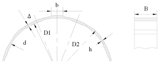
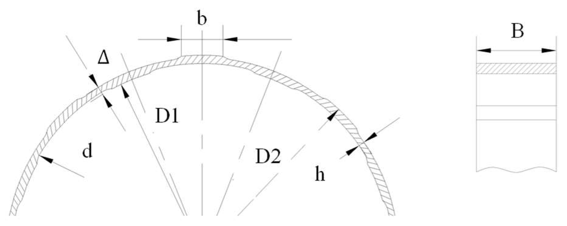
The low-pressure rotor support structure of the engine incorporates an elastic ring, with its schematic diagram shown in Figure 1. Here, D1 denotes the outer diameter of the inner boss surface, D2 represents the inner diameter of the inner boss surface, is the boss height, h stands for the wall thickness, b indicates the boss length, d refers to the root fillet diameter of the boss, and B corresponds to the axial length of the elastic ring.
Figure 1.
Elastic Ring Structure Schematic.
2.2. Analytical Solution
The analytical stiffness expression of the elastic ring is derived based on curved beam theory combined with Castigliano’s second theorem. The elastic ring is idealized as a thin-walled slotted circular beam subjected to radial loading. The following assumptions are adopted: (i) the material is homogeneous and linearly elastic; (ii) bending deformation dominates; (iii) shear deformation is neglected; (iv) small deformation theory applies.
For a circular beam with mean diameter Dm and width B, the second moment of area is:
Under radial force F, the bending strain energy of the ring can be expressed as:
where M is the circumferential bending moment distribution and E is Young’s modulus.
According to Castigliano’s theorem, the radial displacement at the load application point is:
Thus, the equivalent radial stiffness is defined as:
Substituting the strain energy formulation and integrating along the circumferential direction yields the fundamental stiffness form, indicating that the stiffness is primarily governed by bending rigidity and inversely proportional to the cubic power of the mean diameter.
To account for the effects of slot discontinuities and boss geometry, geometric correction factors are introduced. Incorporating these modifications leads to the analytical stiffness expression:
In Equations (5)–(8), represents the boss height; h denotes the wall thickness; b is the boss width; d indicates the fillet diameter; m stands for the number of boss; corresponds to the inner diameter of the elastic ring; refers to the outer diameter of the elastic ring; B signifies the axial width of the elastic ring; E represents the elastic modulus. The material of the elastic ring is 40Cr.
By substituting the structural parameters of the elastic ring from Table 1 into Equation (1), the calculated stiffness of the elastic ring is 1.468 × 10⁷ N/m.
Table 1.
Structural parameters of the elastic ring.
3. Finite Element Analysis of Elastic Ring Stiffness
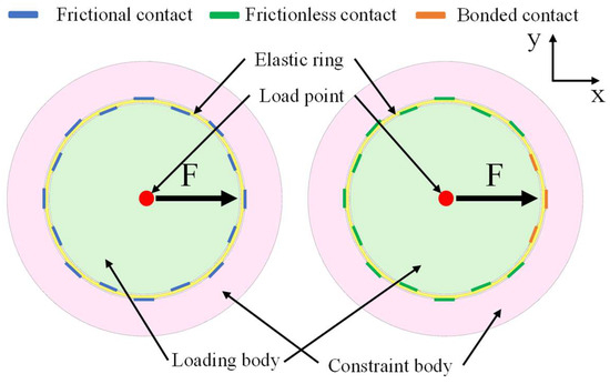
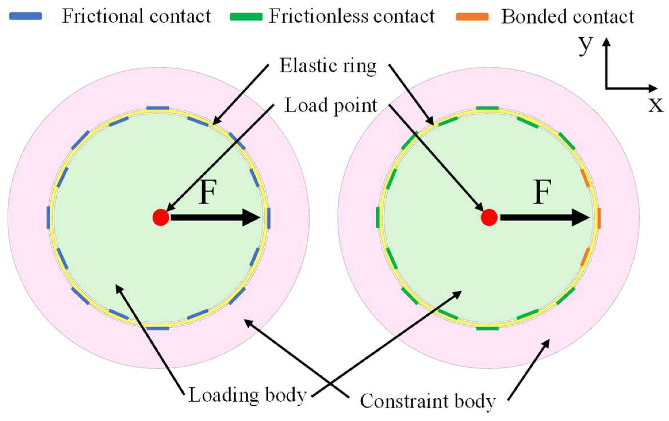
The power turbine rotor support structure of a turboshaft engine incorporates an elastic ring, with its key parameters provided in Table 1. To account for the effects of contact interactions, adjacent inner and outer ring structures are introduced on both sides of the elastic ring model to simulate the bearing and bearing housing, as illustrated in Figure 2. The inner ring features several uniformly distributed bosses oriented radially inward, which contact the outer race of the bearing. Conversely, the outer ring is equipped with an equal number of circumferentially uniformly arranged bosses, positioned alternately with respect to those on the inner ring. These bosses on the outer ring provide support against the inner wall of the casing or bearing housing. The main structural parameters of the elastic ring include boss height, number of bosses, wall thickness, and width.
Figure 2.
Schematic diagram of different contact states of the elastic ring.
The stiffness characteristics of the elastic ring are closely related to the contact behavior of the lugs. To investigate this relationship, two distinct contact conditions—“frictional contact” and “bonded + frictionless contact”—were employed to analyze the stiffness properties of the elastic ring. To enhance the reliability of the simulation results, a radial force was applied along the X-direction at the center of the inner ring of the bearing to simulate the load borne by the bearing. All circumferential degrees of freedom of the nodes on the outer surface of the bearing housing were fully constrained to replicate the restrictive conditions acting on the housing. Since the axial movement of the elastic ring is restricted during damper operation, axial motion constraints were imposed on the ends of the bearing housing, bearing, and elastic ring, thereby strictly limiting their movement to radial displacement. Schematic diagrams of the two contact conditions are shown in Figure 2. The software used for the finite element simulation is ANSYS 15.0.
3.1. Grid Independence Verification
In finite element analysis, to ensure the reliability of computational results, a global mesh independence verification should first be conducted to confirm that the mesh density no longer significantly influences the global solution. On this basis, local mesh refinement can be performed in critical regions to enhance the solution accuracy in areas with stress concentration or high gradient variations. Although global mesh refinement can further improve accuracy, it leads to a sharp increase in computational cost. Therefore, an adaptive meshing strategy is commonly adopted in engineering practice: coarser meshes are used in regions with smooth stress variations and away from boundaries, while local refinement is implemented in areas of interest. This approach not only ensures computational accuracy but also significantly improves solution efficiency, thereby achieving rational allocation of computational resources.
3.1.1. Comprehensive Grid Independence Analysis
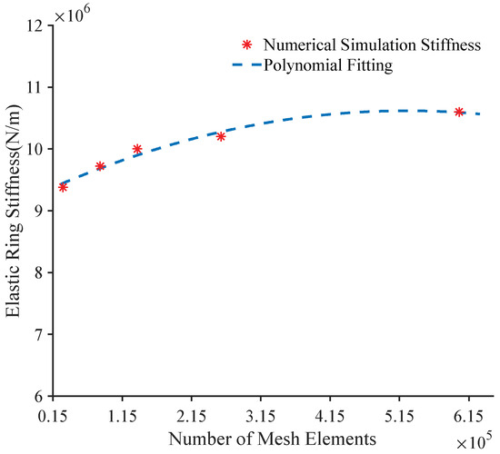
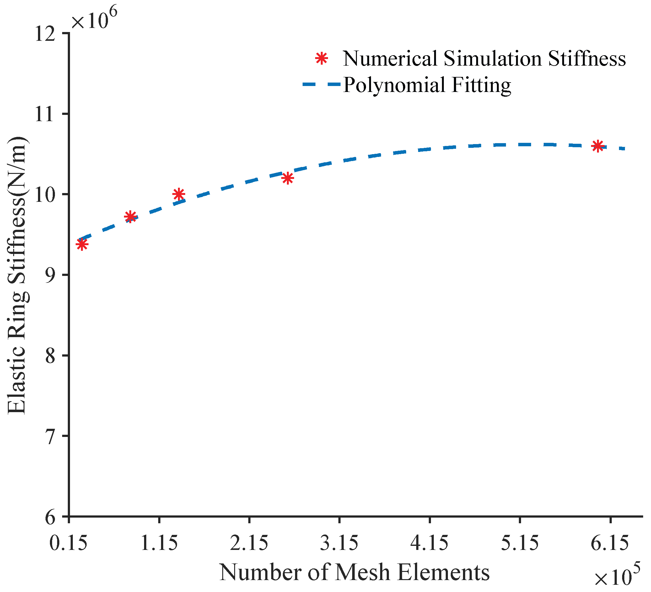
The computational model adopts the “bonded + frictionless contact” configuration shown in Figure 2. A grid independence study was conducted on the entire elastic ring. The ring was discretized using hexahedral elements, with both the inner and outer rings subdivided into multiple mesh layers. The global mesh size was systematically refined from 1.1 mm step by step. The results (Figure 3) indicate that when the number of elements exceeds 257,466 (corresponding to a critical mesh size of 0.5 mm), the numerical solution of the elastic ring’s stiffness converges to a stable value. The mesh sizes and corresponding element quantities are summarized in Table 2. To ensure computational accuracy while considering computational time, the global mesh size was ultimately determined to be 0.5 mm.
Figure 3.
Grid independence of the elastic ring assembly.
Table 2.
Correspondence table between grid size and grid quantity.
3.1.2. Mesh Independence Analysis of the Boss Feature
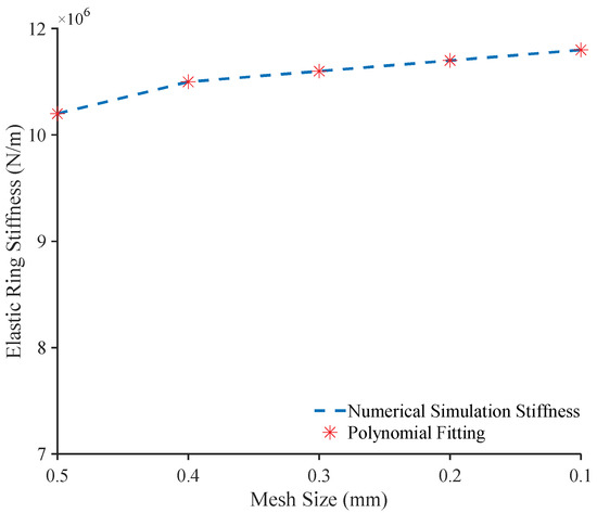
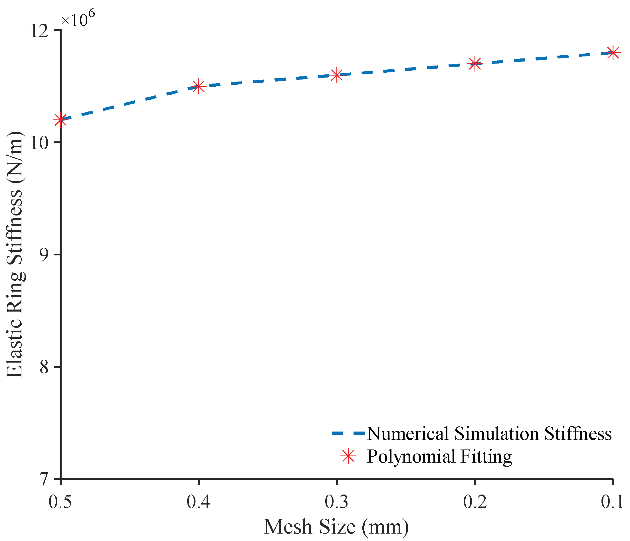
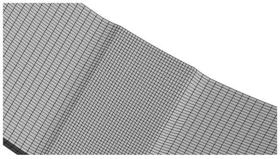
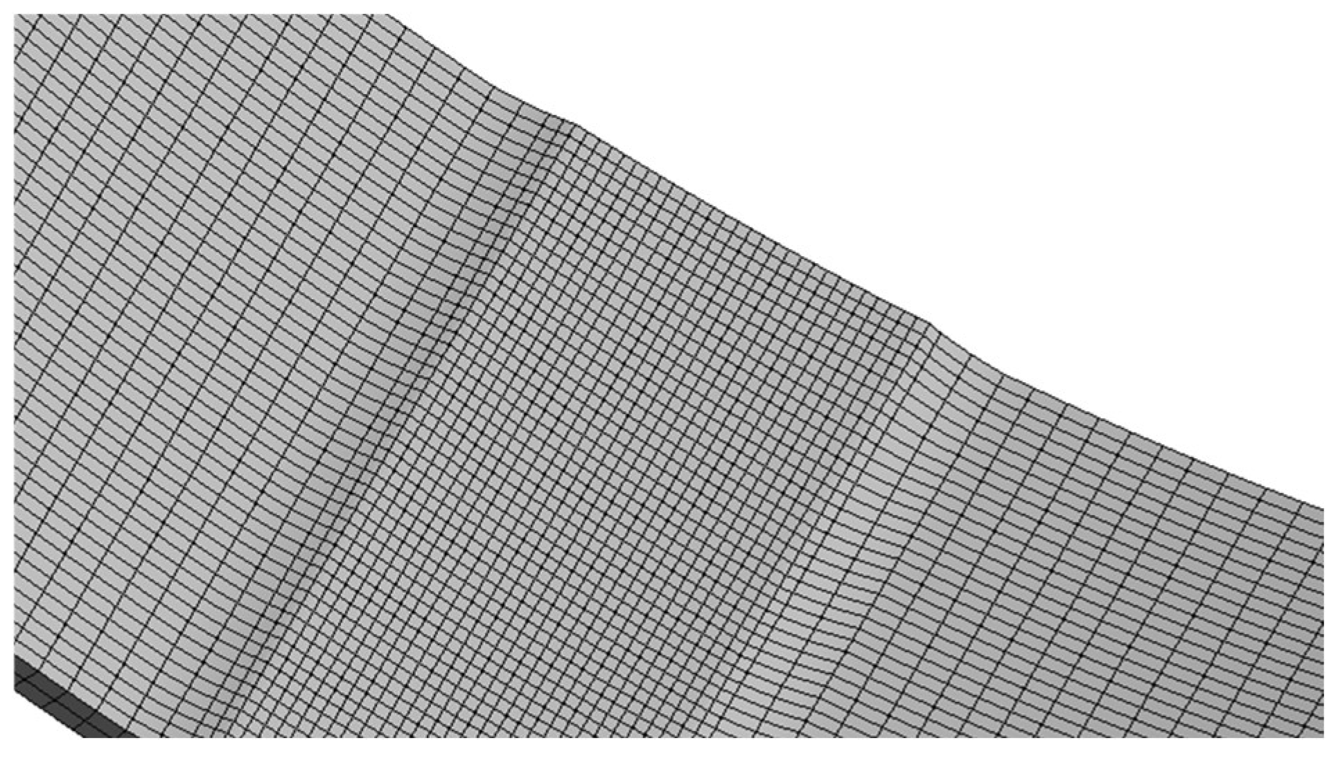
During the mesh independence verification of the elastic ring boss, the entire model was discretized using multi-zone hexahedral elements, with a base mesh size set to 0.5 mm. Local refinement was applied specifically to the boss region. The results (Figure 4) indicate that the simulated stiffness of the elastic ring stabilizes when the mesh size in the boss region is refined to below 0.2 mm. Consequently, a mesh size of 0.2 mm was ultimately selected for the boss region and adopted for all subsequent simulations. The mesh generation for the elastic-ring boss is shown in Figure 5.
Figure 4.
Mesh independence study of the boss feature.
Figure 5.
Network of the elastic-ring bosses.
3.2. The Influence of Varied Contact Conditions on the Stiffness of Elastic Rings
To improve the reliability and authenticity of the simulation results, contact pairs were established between the inner surface of the bearing and the outer lugs of the elastic ring, as well as between the outer surface of the inner shaft sleeve and the inner lugs of the elastic ring, to simulate the contact conditions between the inner and outer lugs of the elastic ring and the corresponding rings. The number of contact pairs corresponds to the number of lugs. In the frictional contact scenario, the friction coefficients between the elastic ring and the inner/outer rings were set to 0.1, 0.15, 0.2, and 0.25, divided into four groups to study the influence of friction coefficient magnitude on stiffness. For the bonded + frictionless contact condition, bonded contacts were applied at the inner lugs aligned with the force application direction and the two adjacent outer lugs, while the remaining inner and outer lugs were configured with frictionless contact with their respective rings. Schematic diagrams of the two contact conditions are shown in Figure 2.
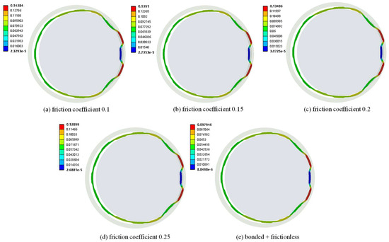
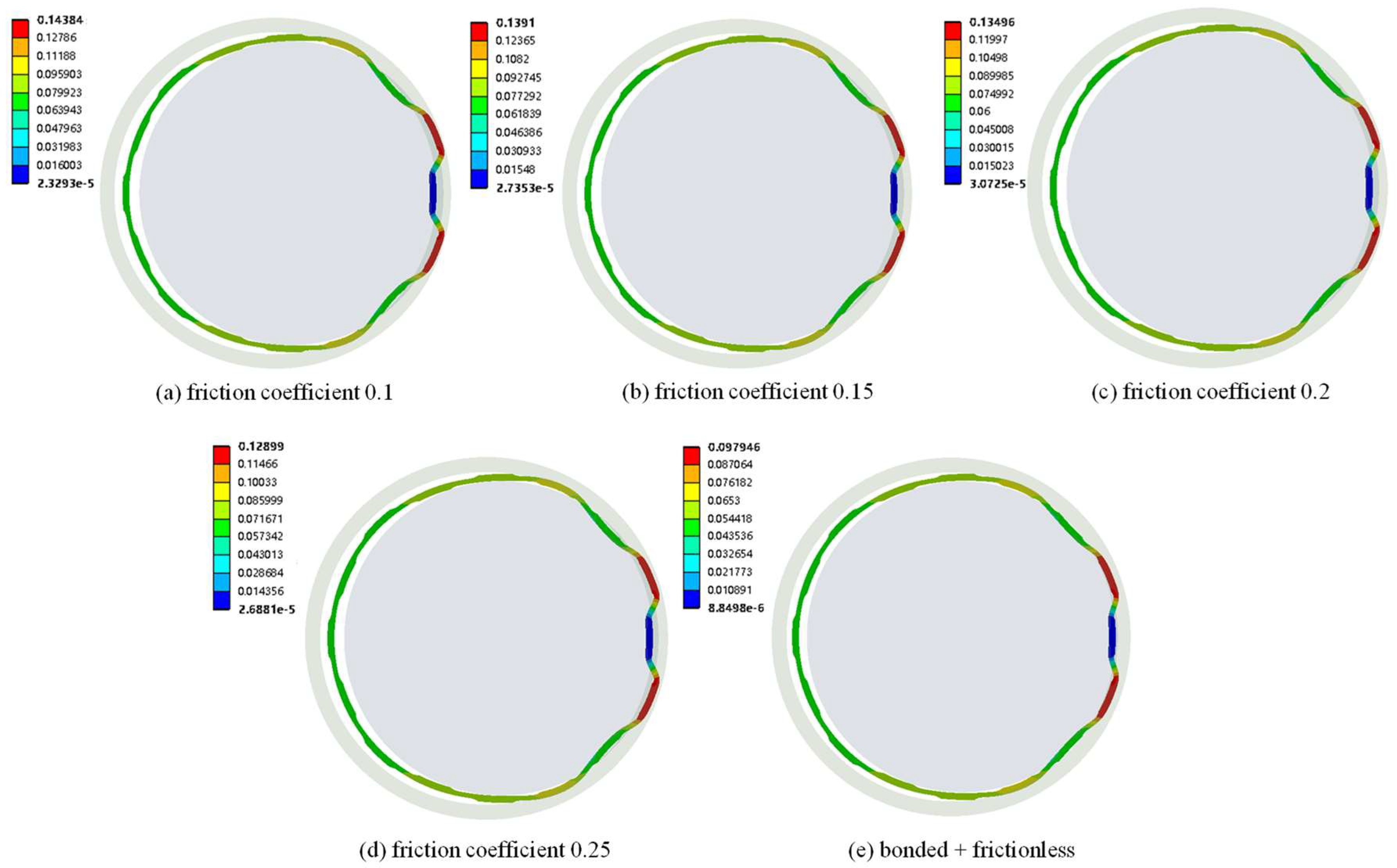
According to the defined contact and constraint settings, the deformation of the elastic ring was calculated. Under a radial load of 1000 N, the deformation results of the elastic ring are shown in Figure 6. The results indicate that when the load is applied, significant deformation occurs in the direction of the applied force, while the deformation on the opposite side, 180° radially apart, is relatively minor. A comparison of different friction coefficients reveals that the deformation of the elastic ring gradually decreases as the friction coefficient increases. Furthermore, under frictionless and bonded contact conditions, the deformation of the elastic ring is minimized.
Figure 6.
Computation results of deformation for elastic rings under various contact conditions.
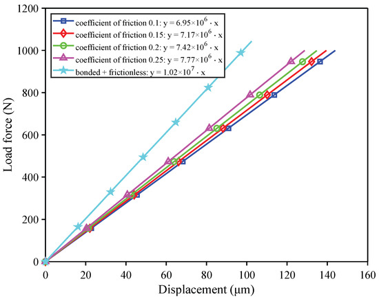
As shown in Figure 7, the displacement response of the elastic ring under various load conditions, obtained through multiple simulation results, clearly demonstrates a well-defined linear relationship between the deformation of the elastic ring and the applied load. By performing linear fitting, the stiffness of the elastic ring under different contact conditions was determined. Under frictionless and bound interface conditions, the stiffness value is 1.02 × 10⁷ N/m. Specifically, when the friction coefficient is 0.1, the stiffness is 6.95 × 10⁶ N/m; at a friction coefficient of 0.15, the stiffness is 7.17 × 10⁶ N/m; at 0.2, it is 7.42 × 10⁶ N/m; and at 0.25, the stiffness reaches 7.77 × 10⁶ N/m.
Figure 7.
Displacement of elastic rings under varied loading conditions.
As the friction coefficient increases from 0.1 to 0.25, the stiffness rises from 6.95 × 10⁶ N/m to 7.77 × 10⁶ N/m, representing an increase of approximately 11.8%. This indicates that friction suppresses micro-slip at the contact interface, enhances the constraining effect, and thereby improves the structural resistance to deformation. At higher friction coefficients, the sticking behavior at the interface becomes more pronounced, reducing energy dissipation and resulting in a higher equivalent system stiffness. Therefore, in the design of bearing seat structures, appropriately increasing the friction coefficient can be an effective strategy for enhancing stiffness. However, potential adverse effects such as wear and heat generation due to increased friction must be comprehensively considered.
The stiffness under bound conditions is significantly higher than that under any frictional condition: it is approximately 46.8% higher than that at a friction coefficient of 0.1, and about 31.3% higher than at a friction coefficient of 0.25. This result indicates that the bound condition entirely eliminates relative displacement at the interface, forming a rigid connection between the elastic ring and the inner/outer rings. As a result, the overall structure becomes more continuous and unified, achieving maximum stiffness. Although increasing friction enhances stiffness, even at a friction coefficient of 0.25, the stiffness remains considerably lower—by approximately 31.3%—than that under the frictionless and bound condition. This demonstrates that friction can only partially suppress slip and cannot fully eliminate interface compliance, whereas binding provides complete constraint.
3.3. The Influence of Boss Thickness on the Contact State of Elastic Rings
3.3.1. Elastic Ring Structures with Varied Boss Thickness
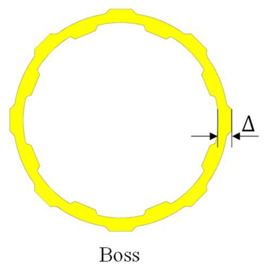
Due to machining tolerances, the thickness of all bosses may increase or decrease. To analyze the influence of boss thickness on elastic contact behavior and stiffness, the nominal thickness at this location is taken as 1.5 mm (Figure 8). Variations of ±0.02 mm and ±0.04 mm from this nominal value are considered to evaluate their impact on stiffness, with identical thickness changes applied simultaneously to all other bosses. The resulting thickness values for this boss under the different variation cases are summarized in Table 3, corresponding to a total of five distinct boss thickness configurations.
Figure 8.
Elastic rings with varying boss thicknesses.
Table 3.
Thickness values of different bosses.
3.3.2. Loading Process of Elastic Rings with Varied Boss Thickness
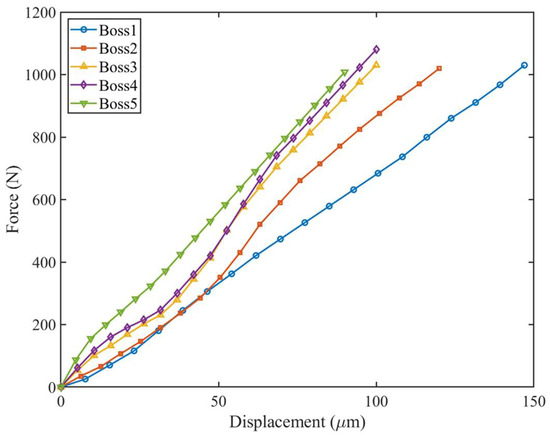
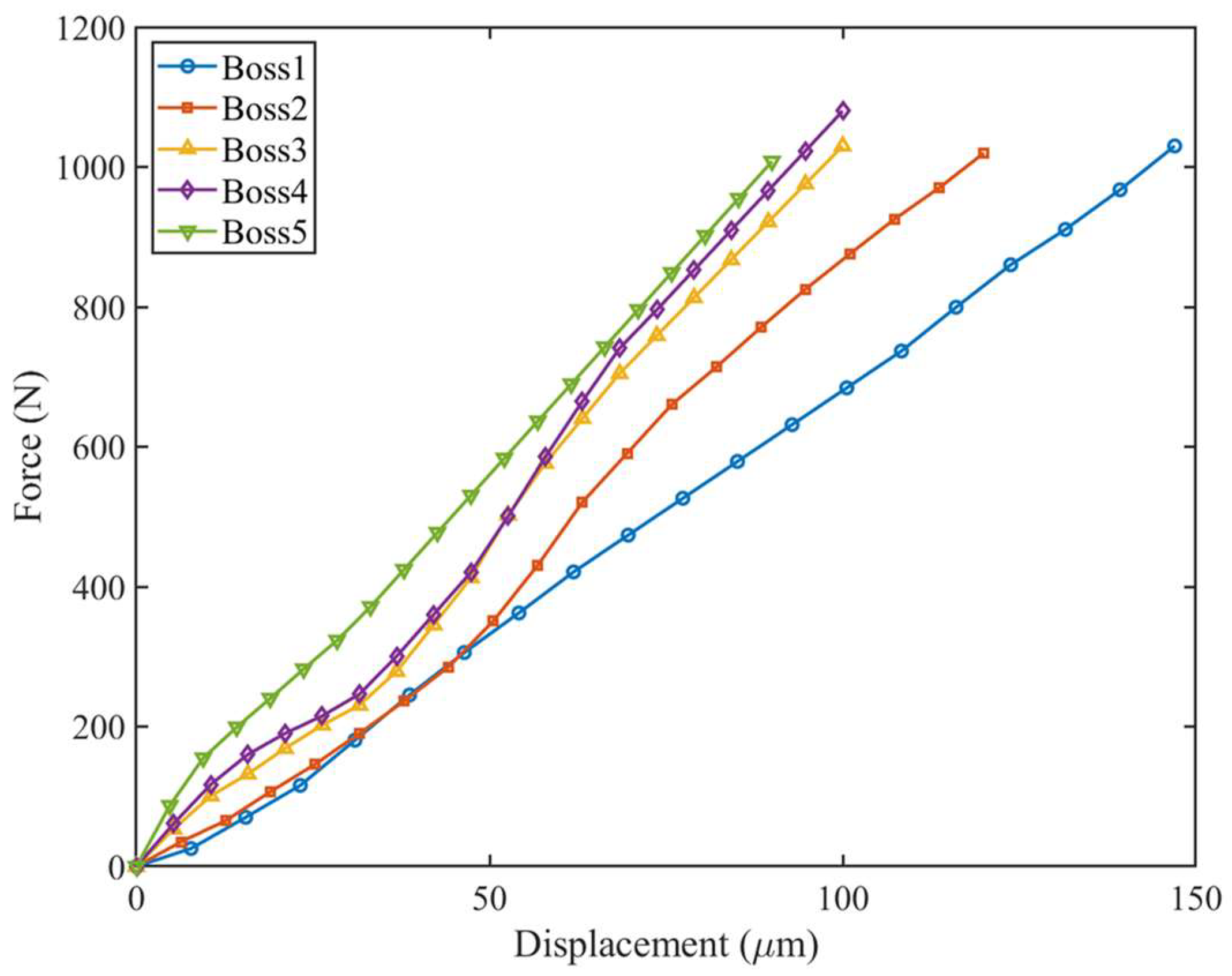
Through simulation calculations performed on five bosses with varying thicknesses on the elastic ring, the corresponding load–displacement curves were obtained, as shown in Figure 9. The influence of contact state on the system stiffness was emphasized in the analysis. The simulation results indicate that differences in boss thickness directly lead to significantly distinct initial preload conditions at the contact interface during the early loading stage, which constitutes the primary cause of localized stiffness variation. Due to their smaller thickness and structural stiffness, Bosses 1 and 2 exhibit a slight initial assembly gap with the outer sleeve and the load-bearing beam under initial load, or have not yet reached effective contact pressure, remaining in a “non-tight” state. As a result, when loading begins, the applied load is first consumed in overcoming this initial gap, gradually causing local deformation of the thinner bosses until full contact is established with the outer sleeve/load-bearing beam. This process of gap closure and contact formation dominates the initial loading phase, manifesting as very low effective initial stiffness until complete contact is achieved. In contrast, owing to their greater thickness and structural stiffness, Bosses 3, 4, and 5 are already in effective contact—i.e., a “tight” state—with the outer sleeve and the load-bearing beam under initial load. This implies the presence of initial contact pressure and preload force at the interface from the onset of loading. When subjected to incremental loads, the system primarily exhibits elastic deformation of the ring segments (non-boss regions) and the thick bosses themselves, with minimal contact deformation, resulting in very high initial contact stiffness.
Figure 9.
Load–displacement curves of elastic rings with varied boss thicknesses.
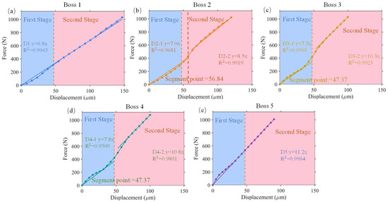
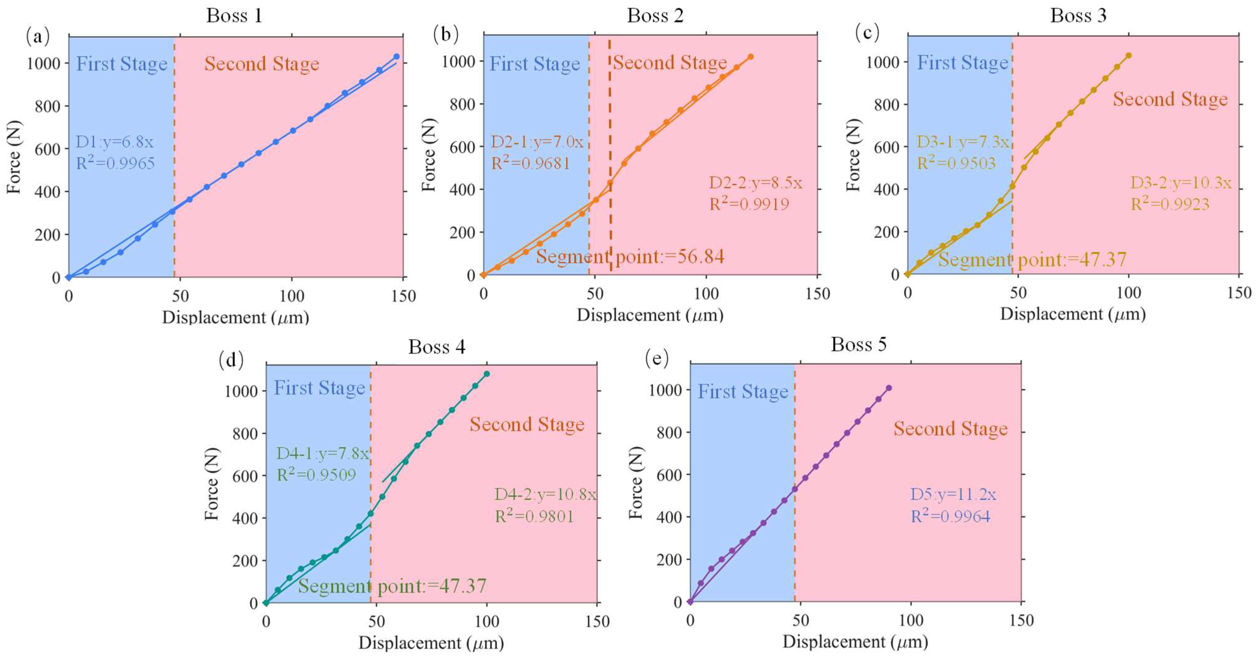
Through the analysis of the loading process of the five convex platforms of the elastic ring, it was found that Convex Platforms 1 and 5 maintain constant linear stiffness, with the stiffness of Convex Platform 1 being 6.8 × 10⁶ N/m and that of Convex Platform 5 being 1.12 × 10⁷ N/m. In contrast, Convex Platforms 2, 3, and 4 exhibit significant bilinear stiffness characteristics during loading. Specifically, the average stiffness of Convex Platform 2 in Stage I is 7 × 10⁶ N/m, which increases sharply to 8.5 × 10⁶ N/m in Stage II; the average stiffness of Convex Platform 3 in Stage I is 7.3 × 10⁶ N/m, rising to 1.03 × 10⁷ N/m in Stage II; and the average stiffness of Convex Platform 4 in Stage I is 7.8 × 10⁶ N/m, increasing to 1.08 × 10⁷ N/m in Stage II. The results are illustrated in Figure 10. By comparing with simulation reference values under frictional contact and frictionless + bonded contact conditions, the underlying physical mechanisms can be explained as follows:
Figure 10.
Force–displacement curves of elastic rings during loading with varied boss thicknesses: (a) Boss 1, (b) Boss 2, (c) Boss 3, (d) Boss 4, (e) Boss 5.
The bilinear stiffness behavior of Convex Platforms 2, 3, and 4 originates from state transitions at the contact interface. For Convex Platform 2 in Stage I, when the load level is low, the shear force at the contact interface remains below the threshold of static friction, and the interface is dominated by frictional contact. The stiffness value was compared with the simulation result under a “friction coefficient of 0.1” (6.95 × 10⁶ N/m), yielding an error of 0.7%, indicating that the stiffness in this stage is constrained by micro-slip at the contact surface. In Stage II, as the contact surface becomes more tightly compressed, the interface transitions from micro-slip to a state of even smaller slip. The stiffness value was compared with the simulation result under a “friction coefficient of 0.25” (7.77 × 10⁶ N/m), resulting in an error of 9%. Similarly, for Convex Platform 3 in Stage I, the interface is dominated by frictional contact. The stiffness value was compared with the simulation result under a “friction coefficient of 0.2” (7.42 × 10⁶ N/m), yielding an error of 1.6%, indicating that the stiffness is limited by micro-slip at the contact surface. In Stage II, as the contact surface is further compressed, the interface transitions from micro-slip to a bonded state. The stiffness value was compared with the simulation result under “frictionless + bonded contact” (1.02 × 10⁷ N/m), resulting in an error of 0.9%. For Convex Platform 4 in Stage I, the interface is also dominated by frictional contact. The stiffness value was compared with the simulation result under a “friction coefficient of 0.2” (7.77 × 10⁶ N/m), yielding an error of 0.3%, again indicating stiffness limitation by micro-slip. In Stage II, as the contact surface becomes more tightly compressed, the interface transitions from micro-slip to a bonded state. The stiffness value was compared with the simulation result under “frictionless + bonded contact” (1.02 × 10⁷ N/m), resulting in an error of 5.8%. This bilinear stiffness phenomenon reveals a dynamic transition in contact behavior from frictional contact dominance to bonded contact dominance.
Throughout the uniaxial loading process, Convex Platform 1 exhibits a single linear force–displacement relationship with a stiffness of 6.8 × 10⁶ N/m. The stiffness value was compared with the simulation result under a “friction coefficient of 0.1” (6.95 × 10⁶ N/m), yielding an error of 2.1%, indicating that the contact interface remains dominated by frictional contact throughout the entire loading process. Similarly, Convex Platform 5 maintains a single linear force–displacement relationship with a stiffness of 1.12 × 10⁷ N/m. The stiffness value was compared with the simulation result under “frictionless + bonded contact” (1.02 × 10⁷ N/m), resulting in an error of 9.8%, indicating that the contact interface remains dominated by bonded contact throughout the entire loading process.
Through the analysis of stiffness and contact states during the loading process of elastic rings with different boss thicknesses, the following conclusions are drawn: First, an insufficient boss thickness results in a frictional contact state between the elastic ring and both the outer ring of the bearing and the inner ring of the housing throughout the entire loading process. When such an elastic ring is applied in subsequent rotor system tests, minor axial and circumferential slippage may occur. Second, an excessive boss thickness leads to a bonded contact state between the elastic ring and both the outer ring of the bearing and the inner ring of the housing during the entire loading process. Consequently, when installed in a rotor system, such an elastic ring may cause assembly difficulties and even jamming. In summary, the design of the boss thickness plays a critical role in both the assembly process and the stiffness characteristics of the elastic ring. The boss thickness should be controlled within a tolerance of 0.02 mm. Based on the above analysis results, the structural parameters of the elastic ring selected for subsequent experiments are presented in Table 1.
4. Stiffness Test of Elastic Ring
4.1. Experimental Apparatus
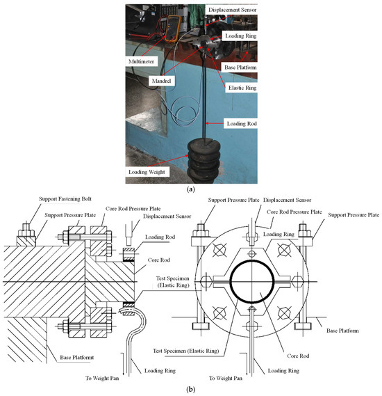
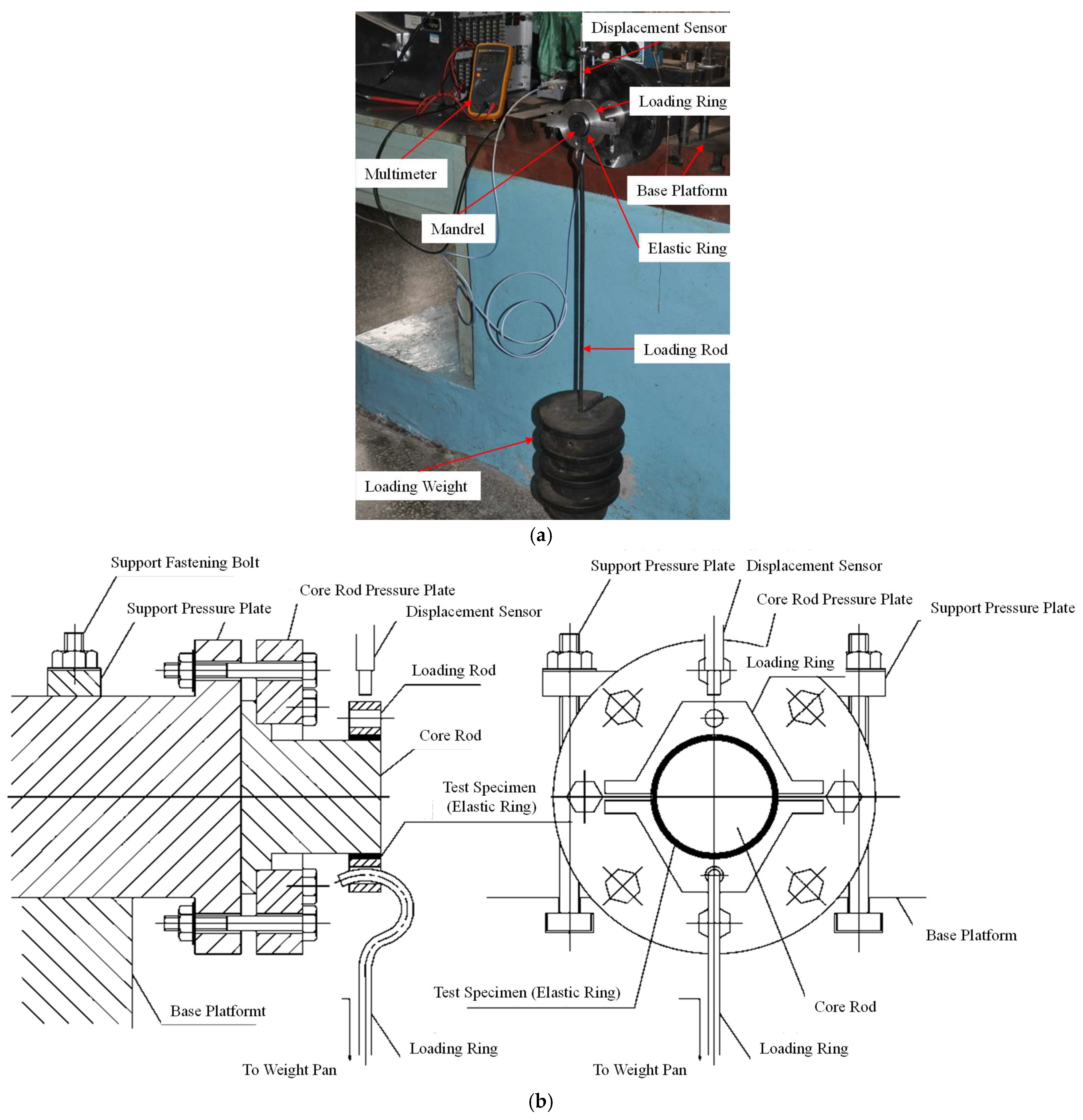
To ensure the consistency of the fit relationship during the stiffness measurement of the elastic ring with its actual assembly condition in the engine (interference fit for the inner ring and transition fit for the outer ring to prevent relative sliding), a dedicated fixture was designed to simulate the elastic ring’s assembly relationship. The actual measurement setup is shown in Figure 11.
Figure 11.
Stiffness measurement photo of elastic ring. (a) Experimental measurement of the elastic ring stiffness. (b) Schematic diagram of the elastic ring stiffness measurement.
Force loading was applied by adding weights to the lower end of the loading rod, while the deformation at the upper plane of the loading ring was measured using an eddy current displacement sensor. The stiffness of the elastic ring was then determined through linear fitting according to Equation (9).
In Equation (9), K represents the elastic ring stiffness, F denotes the variation in test load, and S signifies the displacement.
4.2. Experimental Results and Analysis
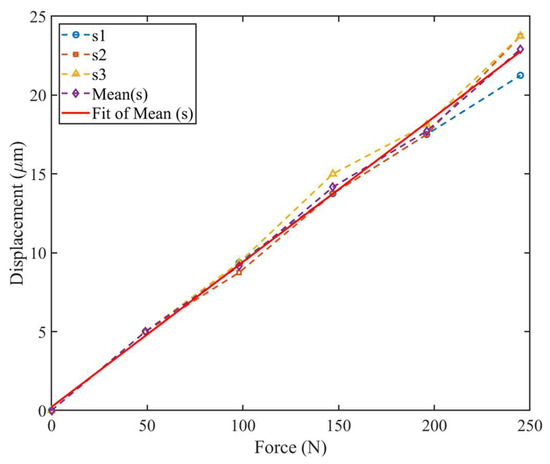
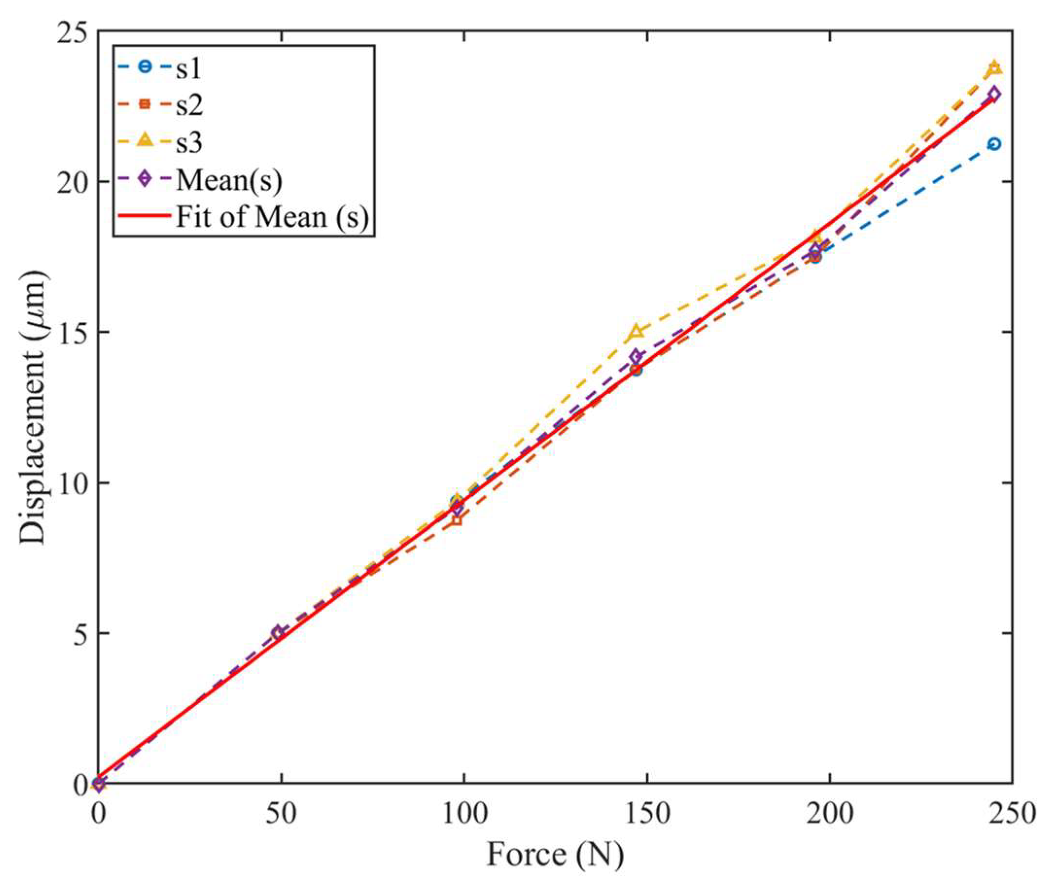
To improve measurement accuracy, the stiffness was measured three times, with the average value adopted as the final result. Based on the measurements obtained from each test, the average value of the elastic ring was calculated, and a fitted curve was generated using this average value to determine the measured stiffness of the elastic ring. The fitted curve of the elastic ring stiffness is shown in Figure 12. The specific measurement data are presented in Table 4.
Figure 12.
Fitted curve of the elastic ring stiffness.
Table 4.
Stiffness measurement results of elastic ring.
According to Table 4, the experimentally measured stiffness of the elastic ring is 1.071 × 10⁷ N/m. The stiffness values obtained from both analytical and finite element methods were compared with the experimental measurements, and the computational errors of these two methods are presented in Table 5.
Table 5.
Stiffness calculation errors of elastic ring.
As shown in Table 5, compared with the experimentally measured stiffness values of the elastic ring, both the analytical method and finite element method (FEM) yield higher stiffness predictions. Specifically, the analytical solution exhibits a significant calculation error of 37.07%, whereas FEM demonstrates a substantially smaller error of only 4.7%. The comparative results clearly indicate that FEM provides superior accuracy with reduced computational error. This discrepancy primarily arises because the analytical method employs generalized empirical formulas that fail to account for the actual working conditions, including the fit relationships of the elastic ring and experimental constraints, consequently leading to larger deviations.
5. Dynamic Characteristic Analysis of Elastic Ring–Rotor System
5.1. Finite Element Model
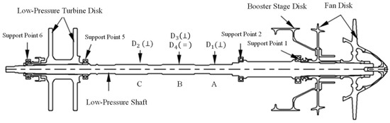
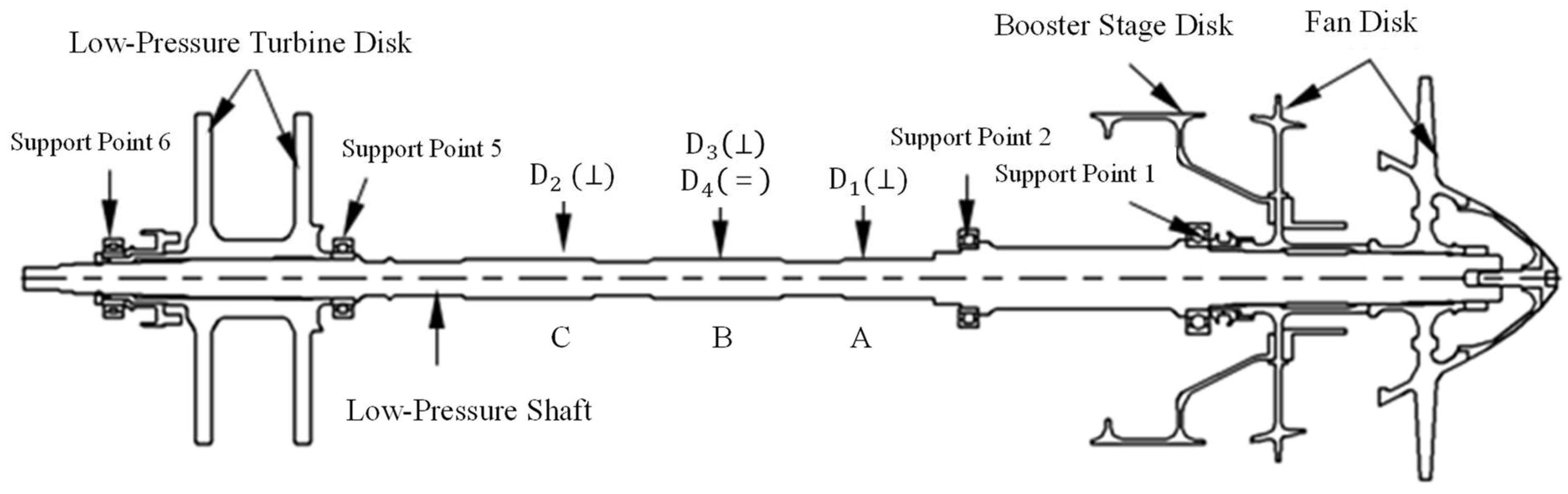
The rotor structure, as shown in Figure 13, consists of two fan disks, a booster stage disk, and two low-pressure turbine disks. The assembly is supported by four bearing points in a 0-3-1 configuration: the No. 1 bearing employs an elastic ring support structure, No. 2 is rigidly supported, while Nos. 5 and 6 utilize squirrel cage elastic supports.
Figure 13.
Schematic diagram of the structure of the rotor system with elastic ring.
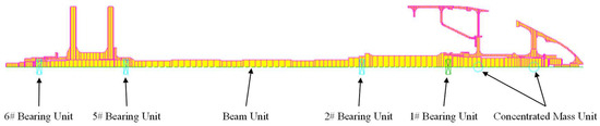
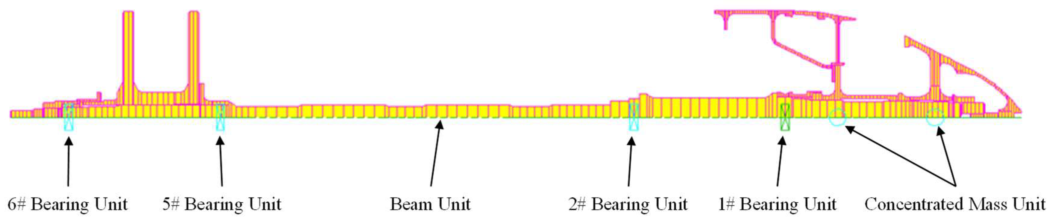
To simplify the modeling process while ensuring the validity of the analysis results, reasonable simplifications were applied to the rotor structure. First, the structure was meshed using two-dimensional beam elements in PATRAN 2019 software. Subsequently, the model (shown in Figure 14) was constructed in SAMCEF/ROTOR specialized analysis software, primarily consisting of concentrated mass elements, bearing elements, and beam elements, with all components connected via rigid elements. For modeling convenience, the circumferentially discontinuous blades on the fan disk and booster stage disk were simulated using concentrated mass elements, incorporating properties such as mass and moment of inertia. The final model comprised 854 beam elements, 876 nodes, 2 concentrated mass elements, and 4 bearing elements.
Figure 14.
Finite element model of the rotor system with elastic ring.
5.2. Dynamic Characteristic Calculation
5.2.1. Vibration Characteristics of Elastic Ring Rotors Solved by Different Methods
Based on the stiffness values of the elastic ring obtained from analytical methods and finite element analysis, the first three critical speeds were calculated without modifying the stiffness of the other supports. The results are presented in Table 6.
Table 6.
Calculation results of critical speed.
5.2.2. Influence of the Elastic Ring Stiffness on the Critical Speed
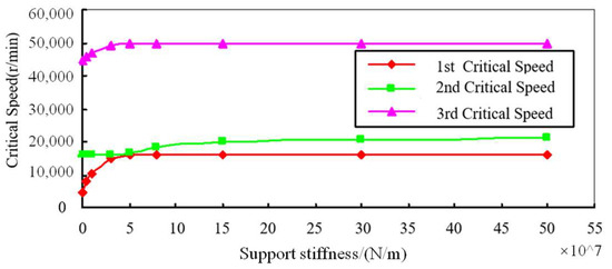
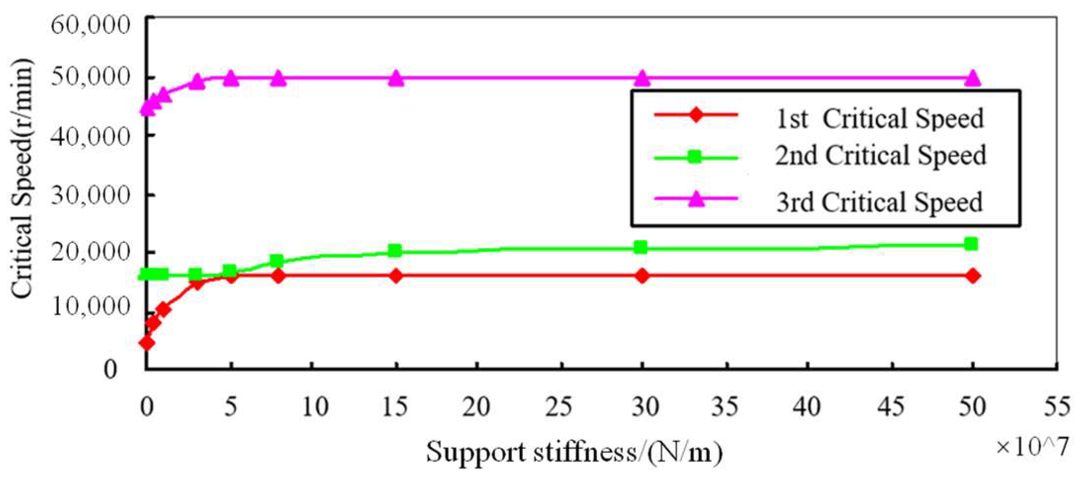
With the support stiffness of Bearings 2, 5, and 6 remaining unchanged as listed in Table 6, the calculated results of the first three critical speeds of the low-pressure rotor were simulated as the support stiffness of Bearing 1 varied from 1 × 10⁶ N/m to 5 × 10⁸ N/m, as presented in Figure 15. When the stiffness of Support 1 varies within a certain range, the rate of change of the first three critical speeds of the simulated low-pressure rotor can be obtained, as shown in Table 7.
Figure 15.
The first three critical speeds as functions of the stiffness of Bearing 1.
Table 7.
Stiffness of Supports 1, 2, 5, and 6.
From Figure 15 and Table 8, when the stiffness of support No. 1 increases from 1 × 10⁶ N/m to 5 × 10⁷ N/m, the first critical speed of the simulated low-pressure rotor rises markedly from 4307 r/min to 15,839 r/min, representing an increase of 267.75%. However, further stiffness increments produce only negligible effects on this critical speed. Within the same stiffness range, the second critical speed increases by only 5.84%. When the stiffness is further increased from 5 × 10⁷ N/m to 1.5 × 10⁸ N/m, the second critical speed rises from 16,803 r/min to 19,728 r/min, an increment of 17.41%. Once the stiffness exceeds 1.5 × 10⁸ N/m and reaches 5 × 10⁸ N/m, the additional increase is limited to 6.91%. In addition, increasing the stiffness from 1 × 10⁷ N/m to 5 × 10⁷ N/m raises the third critical speed by 10.28%, whereas further increases in stiffness do not lead to significant changes.
Table 8.
Variation rates of the first three critical speeds (when Support #1 stiffness changes).
5.3. Rotodynamic Characteristics Testing
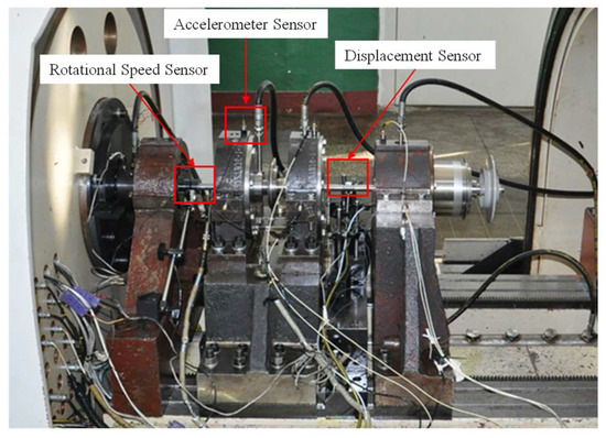
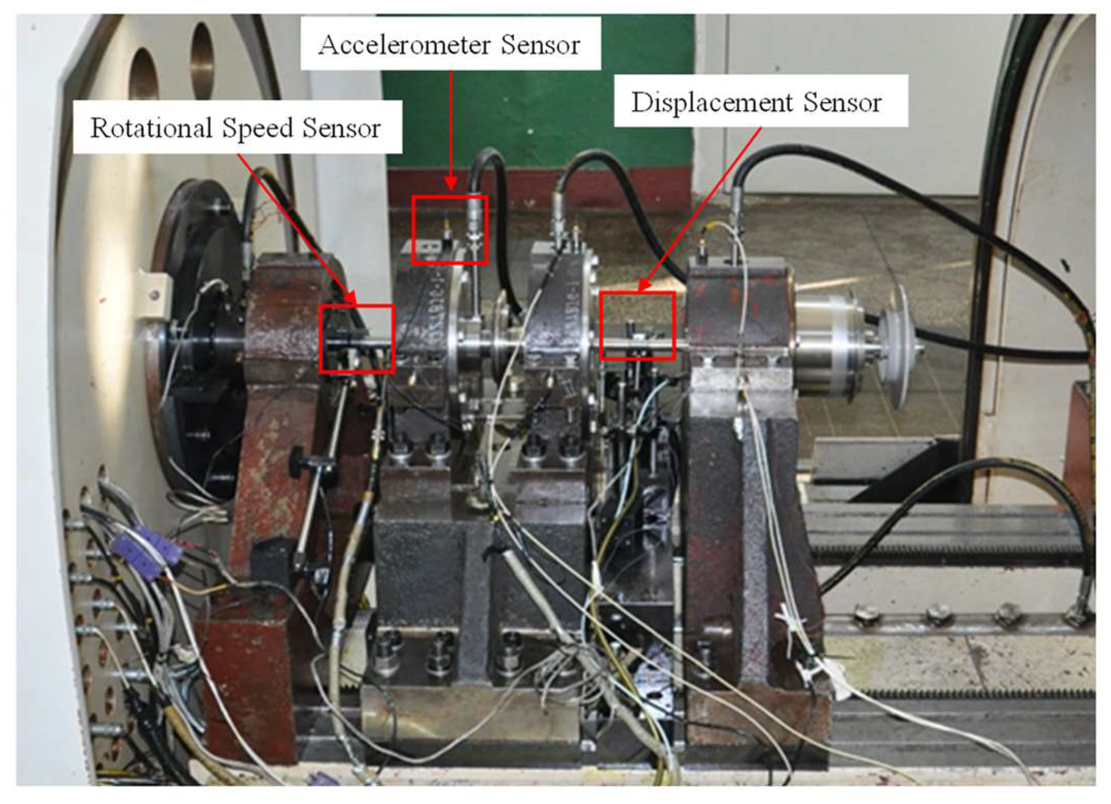
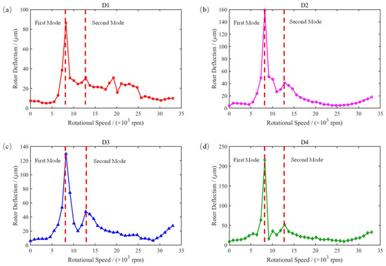
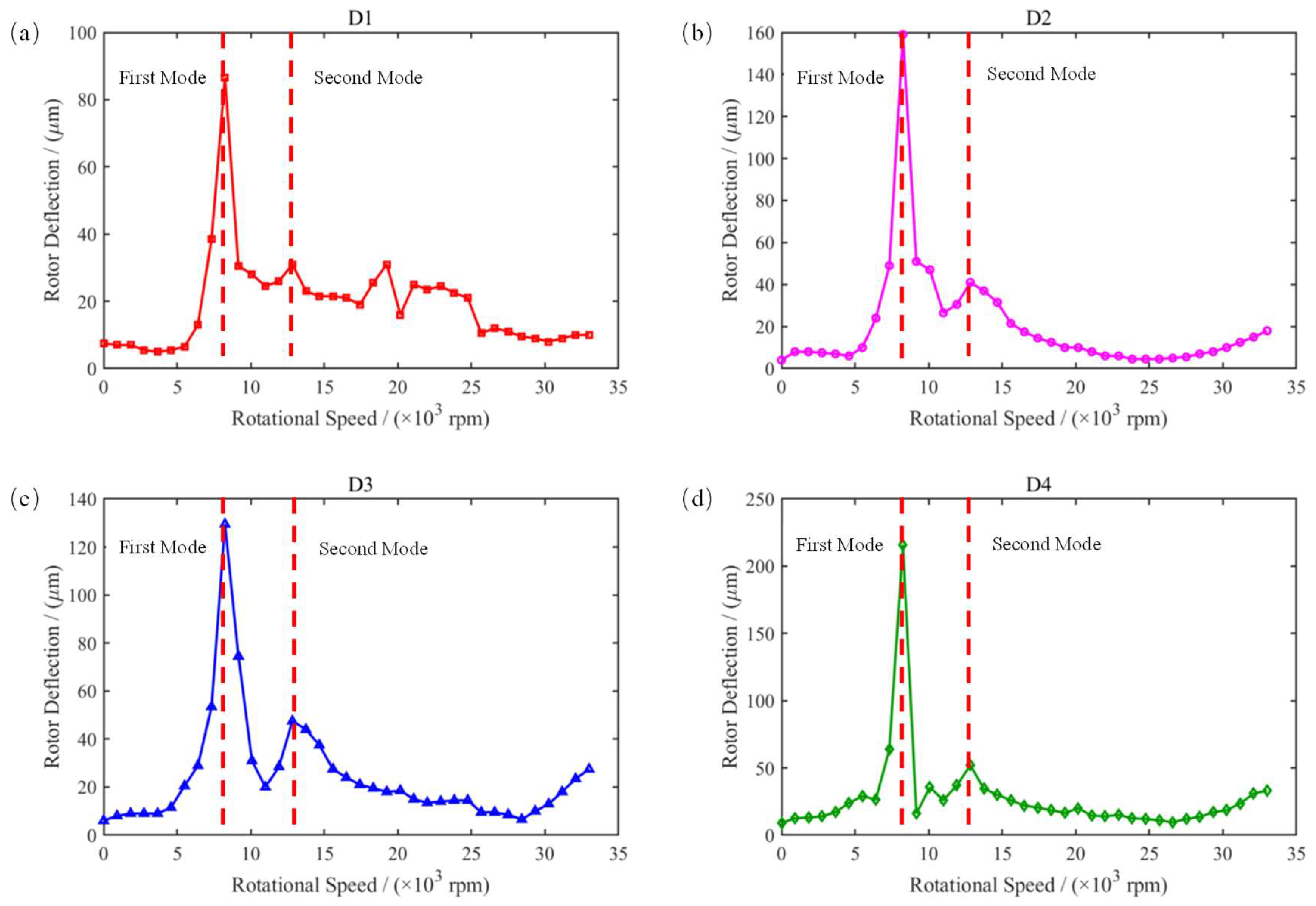
To validate the rotor’s dynamic characteristics design and finite element calculation accuracy, rotor dynamic characteristic tests were conducted. As shown in Figure 16, the rotor was installed on the high-speed rotor tester. Following the configuration in Figure 13, four displacement sensors (D1–D4, model IN085 from BK Company) were mounted at sections A, B, and C as showed in Figure 11 along the rotor shaft to measure rotor deflection during operation. The resulting rotor deflection versus rotational speed curve is presented in Figure 17.
Figure 16.
Installation photo of rotor system with elastic ring.
Figure 17.
Curve of rotor deflection with speed variation at 4 different sensor locations: (a) D1, (b) D2, (c) D3, (d) D4.
Figure 17 identifies the first two critical speeds (corresponding to rotor deflection peaks). Since the rated operating speed nr is significantly lower than the third critical speed and the test only required operation up to the rated speed, the first two critical speeds were selected for comparative analysis. The calculated critical speeds obtained using the measured stiffness were compared with the experimental results, and the computational errors determined by Equation (10) are presented in Table 9.
Table 9.
Critical speed calculation error.
The first two critical speeds of the rotor obtained from finite element calculations show relatively small relative errors compared to those from experimental tests, being 1.8% and 0.25%, respectively, indicating a high level of agreement between the computed and experimental results. The error for the first critical speed between the numerical calculation and the experimental test is larger, reaching 12%, which is primarily attributed to the higher stiffness value of the elastic ring used in the numerical model. At both critical speeds, the rotor exhibited pronounced resonance peaks, indicating bending deformation occurrence. Furthermore, analysis of data from displacement sensors D1 to D4 indicates that the maximum shaft displacement at all critical speeds does not exceed 250 μm, while remaining below 50 μm at the rated speed. This observation aligns perfectly with the computational finding that all modal shapes correspond to bending modes. These results confirm that the established finite element model accurately captures the rotor’s actual dynamic characteristics and fully meets engineering requirements for rotor dynamic analysis.
6. Conclusions
This paper conducted a dynamic characteristic analysis of a rotor system employing an elastic ring structure, with a focus on the influence of different contact states on the stiffness of the elastic ring. The impact of different boss thicknesses on the contact behavior of the elastic ring were investigated. A dedicated test platform was constructed to measure the actual stiffness of the elastic ring, and the results were compared with those obtained from theoretical analysis and finite element method (FEM) simulations. A finite element model of the rotor system was established based on two-dimensional beam elements, and vibration characteristics of the elastic ring–rotor system were tested across the entire speed range. The main findings are as follows:
- The nonlinear stiffness of the elastic ring originates from dynamic transitions in contact states: stiffness drops sharply when the boss and the ring body separate. Increasing the friction coefficient from 0.1 to 0.25 enhances stiffness by 11.8%, yet it remains lower than that under bonded conditions, revealing the inherent limitation of friction constraints in fully eliminating interface compliance. The influence of friction constraints on the stiffness is significant and requires careful consideration when designing the elastic ring to ensure the desired performance across different operational conditions.
- The segmented stiffness characteristics of Bosses 2–4 illustrate a dynamic transition from friction-dominated to bonding-dominated contact behavior. In contrast, the larger gap between Boss 1 and the outer sleeve suppresses contact state transitions, maintaining the system in a friction-sliding dominated regime. Meanwhile, the smaller gap between Boss 5 and the outer sleeve also inhibits transitions, resulting in a bonding-dominated contact state. The findings highlight the importance of accurately designing the gap between the bosses and outer sleeve, as it has a significant effect on the overall stiffness of the system.
- Compared with experimentally measured stiffness values, the errors of the analytical method and the FEM are 37.07% and 4.7%, respectively, indicating the higher accuracy of the FEM. The underlying reason is that the analytical approach relies on general empirical formulas, whereas the finite element method (FEM) incorporates fitting conditions that more closely reflect the actual operating environment and the experimental setup when calculating the stiffness of the elastic ring. Consequently, the FEM offers higher accuracy compared with the analytical method, and its results are more reliable in practical applications.
- The dynamic characteristics of the rotor system calculated using the established two-dimensional beam element model show deviations of only 1.8% and 0.25% compared with experimental data. Furthermore, the rotor system crosses two bending critical speeds within its rated operating range and exhibits favorable vibration performance throughout the entire speed range. This demonstrates the effectiveness of the elastic ring in enhancing rotor stability and mitigating excessive vibrations across various operating conditions.
In addition, it should be noted that the present study primarily focuses on stiffness characteristics and their influence on rotor dynamic behavior, while several factors critical to real aero-engine applications have not been explicitly considered. In particular, the damping effect introduced by the oil film between the elastic ring and the housing, thermal expansion under varying operating temperatures, and long-term fatigue behavior at stress concentration regions (e.g., boss root fillets) may significantly influence the contact state, stiffness evolution, and overall dynamic response of the system. For example, variations in oil film viscosity and thickness could alter the system damping ratio and vibration attenuation capability; thermal effects may induce transitions between frictional and interference contact states, leading to additional stiffness variations; and fatigue damage accumulation could degrade structural integrity and modify stiffness over the service life. Therefore, the applicability of the present results to practical aero-engine conditions should be interpreted with these limitations in mind. Future work will incorporate thermo-mechanical coupling, oil film damping characterization, and fatigue analysis to provide a more comprehensive understanding of the elastic ring–rotor system under realistic operating conditions.
Author Contributions
Conceptualization, W.N.; Methodology, W.N.; Formal analysis, N.Z.; Investigation, Q.Z.; Resources, J.L.; Data curation, Q.Z.; Writing—review and editing, W.N.; Supervision, X.Y. All authors have read and agreed to the published version of the manuscript.
Funding
This research was funded by Technology Innovation Platform Fund Project of AECC (Grant No. is CXPT-2022-031) and the National Natural Science Foundation of China (Grant No. is 52405084) and the Fundamental Research Funds for the Central Universities (Grant No. is 501RCQD2025104001).
Data Availability Statement
Data are contained within the article.
Conflicts of Interest
The authors declare that they have no known competing financial interests or personal relationships that could have appeared to influence the work reported in this paper.
References
- Balyakin, V.B. Advanced designs of elastic damper supports for aircraft engine rotors. Russ. Aeronaut. 2015, 58, 42–47. [Google Scholar] [CrossRef] [Scilit]
- Ravikovich, Y.A.; Balyakin, V.B. Prospects for application and classification of controlled elastic-damping supports. Russ. Aeronaut. 2023, 66, 72–78. [Google Scholar] [CrossRef] [Scilit]
- Pang, G.; Cao, S.; Chen, Y.; Chen, H. Study on vibration and bifurcation of an aeroengine rotor system with elastic ring squeeze film damper. Shock Vib. 2021, 2021, 4651339. [Google Scholar] [CrossRef] [Scilit]
- Chen, J.; Chen, X.; Hong, L.; Ren, G.; Gan, X. Dynamic response simulation method of elastic ring squeeze film damper based on fluid-structure interaction. J. Vib. Eng. 2025, 1–15. Available online: https://link.cnki.net/urlid/32.1349.TB.20250219.1305.002 (accessed on 22 March 2026).
- Ertaş, M.; Yılmaz, A. Dynamic magnetic properties of mixed half-integer (σ = 3/2) and half-integer (S = 5/2) spins: Dynamic effective-field theory. Comput. Condens. Matter 2018, 14, 1–7. [Google Scholar] [CrossRef] [Scilit]
- Xu, Y.; Chen, X.; Zou, J.; Qi, W.; Li, Y. Influence of orifice distribution on the characteristics of elastic ring-squeeze film dampers for flywheel energy-storage system. IEEE Trans. Plasma Sci. 2013, 41, 1272–1279. [Google Scholar] [CrossRef] [Scilit]
- Editorial Board of Aeroengine Design Manual. Aeroengine Design Manual. Volume 19, Rotor Dynamics and Whole Engine Vibration; Aviation Industry Press: Beijing, China, 2000. [Google Scholar]
- Dousti, S.; Gerami, A.; Dousti, M. A numerical CFD analysis on supply groove effects in high pressure, open end squeeze film dampers. Int. J. Eng. Innov. Res. 2016, 5, 80–89. [Google Scholar]
- Long, X.; Hong, J.; Zhang, D.; Lin, H. Research on analytical method and dynamic character of stiffness and strengthen of elastic ring. J. Eng. Therm. Energy Power 2010, 25, 145–149. [Google Scholar]
- Liu, C.; Chen, G.; Yang, Y.; Hou, X.J.; Luo, Z.; Zhang, X.D. Stiffness analysis of elastic ring based on finite element simulation. J. Shenyang Aerosp. Univ. 2019, 36, 8–13. [Google Scholar]
- Liu, W.; Deng, W.; Peng, C.; Sun, Y.; Tang, H. Analysis method on the stiffness of elastic ring and the effect of its structure parameters on the stiffness. Aeronaut. Sci. Technol. 2019, 30, 60–65. [Google Scholar]
- Sharma, S.K.; Milojević, S.; Sharma, L.K.; Gajević, S.; Sharma, Y.; Sharma, M.; Čukić, S.; Stojanović, B. Friction Stir Processing: An Eco-Efficient Route to High-Performance Surface Architectures in MMCs. Processes 2026, 14, 306. [Google Scholar] [CrossRef] [Scilit]
- Skulic, A.; Milojevic, S.; Maric, D.; Ivanovic, L.; Krstic, B.; Radojkovic, M.; Stojanovic, B. The Impact of Lubricant Viscosity and Materials on Power Losses and Efficiency of Worm Gearbox. Teh. Vjesn.-Tech. Gaz. 2022, 29, 1853. [Google Scholar]
- Qi, W.; Chang, L.; Peng, Z.; Song, W. Simulation and test of stiffness of elastic ring assembly. Mech. Manuf. 2022, 60, 74–80. [Google Scholar]
- Diligenskiy, D.S.; Novikov, D.K. Studying of manufacturing tolerance influence on the performance of GTE rotor elastic rings. Procedia Eng. 2017, 176, 483–497. [Google Scholar] [CrossRef] [Scilit]
- Ishida, Y.; Inagaki, M.; Ejima, R.; Hayashi, A. Nonlinear resonances and self-excited oscillations of a rotor caused by radial clearance and collision. Nonlinear Dyn. 2009, 57, 593–605. [Google Scholar] [CrossRef] [Scilit]
- Yabuno, H.; Kashimura, T.; Inoue, T.; Ishida, Y. Nonlinear normal modes and primary resonance of horizontally supported Jeffcott rotor. Nonlinear Dyn. 2011, 66, 377–387. [Google Scholar] [CrossRef] [Scilit]
- Li, B.; Cheng, D.; Jiang, Z. Experiment study on dynamic characteristics of elastic ring squeeze film damper rotor system. Gas Turbine Exp. Res. 2015, 28, 19–22. [Google Scholar]
- Sun, K.; Luo, Z.; Li, L.; Ge, X.; Zheng, S. Assembly characteristics and experimental study of rotor system with elastic ring squeeze film damper. J. Mech. Eng. 2023, 59, 118–131. [Google Scholar]
- Li, Y.; Liao, M.; Wang, S. Effect on vibrating attenuation by the fit of elastic ring squeeze film damper. J. Vib. Shock 2020, 39, 232–238. [Google Scholar]
- Li, S.; Yang, M.; Teng, G.; Yang, F.; Gao, W.; Wang, Y. Experimental equipment for loading and dynamic characteristics of elastic ring squeeze film damper. Gas Turbine Exp. Res. 2023, 36, 17–23. [Google Scholar]
- Luo, Z.; Liu, J.; Li, L.; Wu, F.; Ge, X. Dynamic characteristics analysis of rotor system with fitting tightness of elastic ring support structure. J. Mech. Eng. 2023, 59, 124–132. [Google Scholar]
- Luo, Z.; Liu, J.; Liu, K.; Sun, K. Analysis of dynamic stiffness of the elastic ring support structure and its influence on the rotor system. J. North-East. Univ. (Nat. Sci.) 2022, 43, 667–673. [Google Scholar]
- Xiang, F.; Chen, X.; Hong, L.; Ren, G.; Gan, X. Simulation method for dynamic responses of squeeze film damper-rotor system considering elastic ring deformation. J. Propuls. Technol. 2024, 45, 2402031. [Google Scholar]
- Qin, Y.; Liu, B.; Yin, B.; Hao, L.; Zhao, Q.J.; Zhao, W. Influence of elastic ring structural parameters on ERSFD dynamic system characteristics. J. Aerosp. Power 2024, 39, 20220616. [Google Scholar]
- Zhao, X.; Yang, Y.; Wang, Z.; Lu, K.; Zeng, J.; Yang, Y. Dynamic characteristics of flexible rotor system supported by elastic ring squeeze film damper. J. Dyn. Control 2024, 22, 43–51. [Google Scholar]
- Shi, Y.; Li, J.; Yang, Z. Finite element analysis of structural parameter effects on stiffness nonlinearity behaviour in aero-engine elastic rings. Aerospace 2025, 12, 338. [Google Scholar] [CrossRef] [Scilit]
- Zhou, J.; Luo, Z.; Li, L.; Ma, T.; Li, H. Numerical and experimental analysis of the influence of elastic supports on bearing-rotor systems. Mech. Syst. Signal Process. 2025, 224, 112235. [Google Scholar] [CrossRef] [Scilit]
- Zhang, W.; Ding, Q. Elastic ring deformation and pedestal contact status analysis of elastic ring squeeze film damper. J. Sound Vib. 2015, 346, 314–327. [Google Scholar] [CrossRef] [Scilit]
- Han, Z.; Ding, Q. Dynamical analysis of an elastic ring squeeze film damper-rotor system. Mech. Mach. Theory 2019, 131, 406–419. [Google Scholar] [CrossRef] [Scilit]
- Sun, K.; Luo, Z.; Li, L.; Wu, F.; Hao, H. Mechanical and vibration characteristics investigation of the elastic ring squeeze film damper-rotor considering oil film sealing and leakage. Int. J. Non-Linear Mech. 2024, 161, 104701. [Google Scholar] [CrossRef] [Scilit]
- Hong, J.; Han, Z.; Wang, Y.; Lyu, D.; Song, Z.; Yang, Z.; Ma, Y. Influence of structural features on oil film dynamics of elastic ring-supported rotor systems. J. Vib. Control 2025. [Google Scholar] [CrossRef] [Scilit]




Disclaimer/Publisher’s Note: The statements, opinions and data contained in all publications are solely those of the individual author(s) and contributor(s) and not of MDPI and/or the editor(s). MDPI and/or the editor(s) disclaim responsibility for any injury to people or property resulting from any ideas, methods, instructions or products referred to in the content. |
© 2026 by the authors. Licensee MDPI, Basel, Switzerland. This article is an open access article distributed under the terms and conditions of the Creative Commons Attribution (CC BY) license.