1. Introduction
With the continuous advancement of manufacturing toward higher precision, reliability, and green low-carbon development, effective control of machine tool thermal errors has become one of the key factors constraining further improvements in machining accuracy. Previous studies indicate that thermal errors account for approximately 40–70% of the total error sources in precision CNC machine tools, and their variation directly affects dimensional accuracy, repeat positioning accuracy, and long-term operational stability [
1,
2,
3,
4,
5]. Therefore, the development of a high-efficiency and low-energy machine tool thermal control system constitutes an essential technological foundation for achieving high-precision machining and green manufacturing.
As the core component responsible for heat transfer between the machine tool thermal control system and structural components, the thermal control plate plays a decisive role in determining both thermal management effectiveness and overall energy consumption. Existing studies on thermal control plates and similar cooling structures primarily focus on enhancing convective heat transfer, through optimization of flow channel configurations, incorporation of heat transfer enhancement elements, or adjustment of operating conditions to increase heat transfer power. However, extensive research on single-phase heat transfer enhancement has demonstrated that improved heat transfer performance is often accompanied by increased pressure drop and pumping power. Previous studies have reported that passive heat transfer enhancement techniques can increase the Nusselt number by approximately 20–50%, while the corresponding pressure drop may rise by 30–80%, leading to a noticeable increase in pumping power consumption [
6,
7,
8]. Consequently, under machine tool thermal control scenarios, structural optimization driven solely by heat transfer performance is insufficient to satisfy the integrated requirement of high efficiency and low energy consumption. Achieving a balance between heat transfer enhancement and flow resistance control has therefore become a key challenge in the design of thermal control plates. Achieving an effective balance between high heat transfer capacity and low flow resistance within a given operating range remains a critical issue in the design and engineering application of thermal control plates.
Under high-flow operating conditions in machine tool thermal control systems, the demand for the simultaneous realization of high heat transfer capacity and low energy consumption becomes particularly pronounced. Conventional approaches that rely on increasing flow velocity to enhance convective heat transfer can improve heat transfer power but typically result in significantly higher pressure drop and pumping power, ultimately leading to reduced system energy efficiency [
9,
10,
11]. In this context, passive heat transfer enhancement structures have attracted growing attention due to their lack of additional energy input and relatively simple structural configurations. Among them, vortex-inducing structures and microchannel structures represent two representative passive enhancement strategies.
Vortex-inducing structures enhance convective heat transfer by promoting vortex generation, flow separation, and reattachment within the channel, thereby intensifying fluid mixing and boundary-layer renewal and increasing both the convective heat transfer coefficient and heat transfer power. Numerous studies and reviews have demonstrated that vortex-generator-type structures exhibit strong heat transfer enhancement capability. Experimental studies have shown that vortex generators can increase the average convective heat transfer coefficient by approximately 25–40% compared with smooth channels, although the associated friction factor may increase by more than 50% in certain channel configurations [
12,
13,
14,
15]. In contrast, microchannel structures enhance convective heat transfer by introducing microscale channels within flow passages or fin surfaces. Due to the significantly increased surface-to-volume ratio, microchannel heat sinks can achieve heat transfer coefficients several times higher than those of conventional channels [
16,
17,
18,
19]. At the same time, a rationally designed microchannel structure can effectively control the flow resistance to a certain extent. For example, early studies on microchannel cooling demonstrated that heat flux dissipation levels exceeding several hundred W/cm
2 can be achieved using properly designed microchannel heat sinks [
20,
21,
22,
23,
24].
From the perspective of engineering feasibility and parametric controllability, microchannel size and number are critical design parameters influencing the comprehensive performance of thermal control plates. However, under complex channel networks or high-flow operating conditions, microchannel structures may lead to flow maldistribution, thereby restricting local heat transfer performance and limiting further improvements in overall system performance [
25,
26,
27,
28]. It can therefore be concluded that vortex-inducing structures and microchannel structures exhibit complementary advantages in enhancement mechanisms and performance characteristics. However, most existing studies focus on single heat transfer enhancement structures or conventional heat exchanger applications, and the combined effects of vortex-inducing and microchannel structures on both heat transfer and energy efficiency of machine tool thermal control plates remain insufficiently investigated.
Based on the above analysis, this study proposes a vortex-inducing–microchannel composite thermal control plate specifically designed for machine tool thermal control systems. By integrating the strong mixing-based enhancement mechanism of vortex-inducing structures with the relatively low-resistance characteristics of microchannel structures, the proposed design aims to achieve synergistic optimization between heat transfer enhancement and energy efficiency improvement. A combined approach of numerical simulation and experimental validation is employed to systematically investigate the effects of key parameters—including vortex-inducing geometry, microchannel size, and microchannel number—on convective heat transfer and energy efficiency under unified boundary conditions. Furthermore, the PEC is introduced to assess the overall enhancement effectiveness of the composite structure [
29,
30]. The findings of this study provide theoretical support and engineering guidance for the structural selection and parameter optimization of composite enhanced thermal control plates for machine tools.
The remainder of this paper is organized as follows:
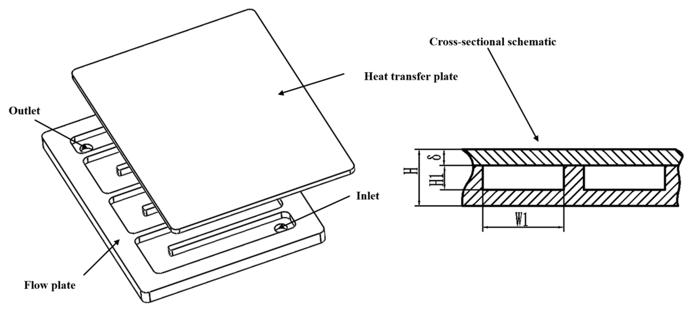
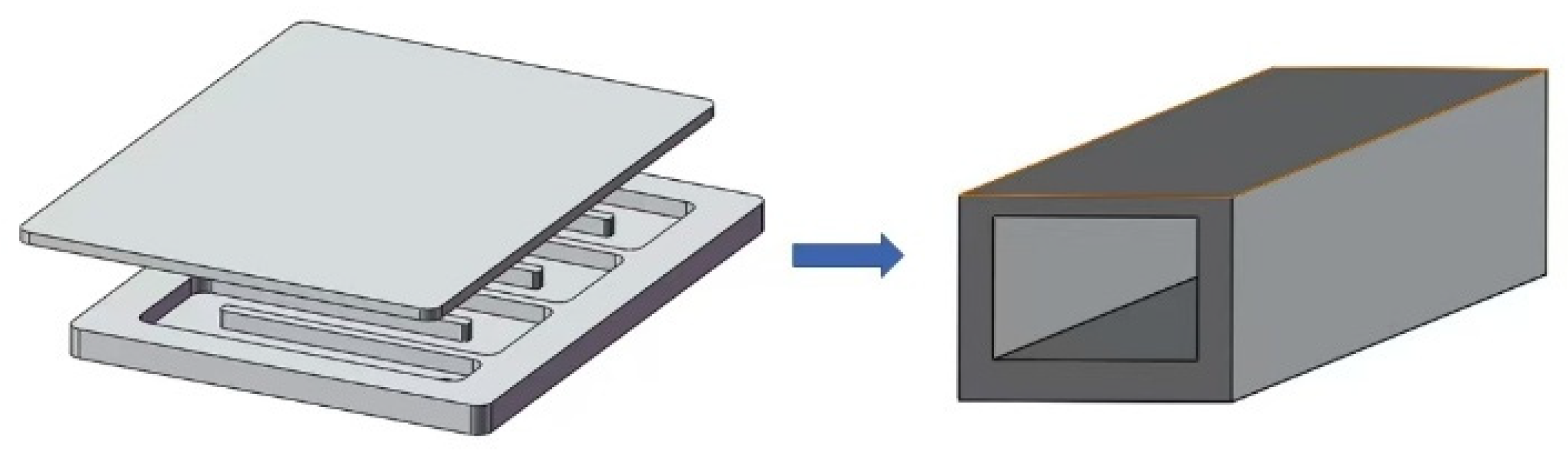
Section 2 introduces the performance evaluation indices and the equivalent modeling method of the thermal control plate.
Section 3 analyzes the heat transfer and flow characteristics of vortex-inducing structures and microchannel structures individually through numerical simulations.
Section 4 further investigates the synergistic performance of the vortex-inducing–microchannel composite structure.
Section 5 presents the experimental validation of the proposed structure.
Section 6 summarizes the main conclusions of this study.
3. Single-Structure Simulation: Performance Characteristics of Vortex-Inducing and Microchannel Structures
3.1. Effect of a Single Vortex-Inducing Structure on the Comprehensive Performance of the Thermal Control Plate
During practical machining operations, when the coolant flows through the bend regions of the flow channel in the thermal control plate, significant variations in flow velocity occur. The centrifugal side experiences an increase in flow velocity, leading to non-uniform flow field distribution. This velocity non-uniformity weakens local convective heat transfer and consequently degrades the overall heat transfer performance of the thermal control plate. Therefore, it is necessary to introduce a vortex-inducing structure into the flow channel to improve flow uniformity and enhance the comprehensive heat transfer capability of the thermal control plate.
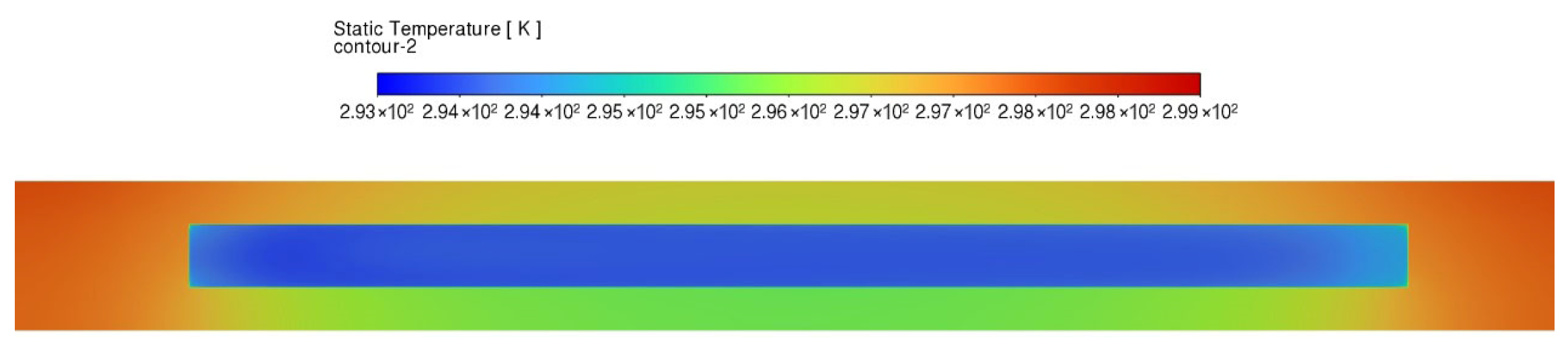
The vertical cross-sectional temperature field distribution of the thermal control plate is shown in
Figure 3. Since heat is transferred sequentially from the heat source downward through the plate, the heat transfer surface on the heat transfer plate side exhibits a higher temperature level than that on the flow plate side. Based on this characteristic, the vortex-inducing structures are arranged on the surface of the heat transfer plate to fully exploit the heat transfer enhancement potential on the high-temperature side. Furthermore, to improve the flow uniformity of the coolant within the channel, the vortex-inducing structures are positioned at the center of the flow channel, thereby achieving synergistic enhancement of both flow and heat transfer performance:
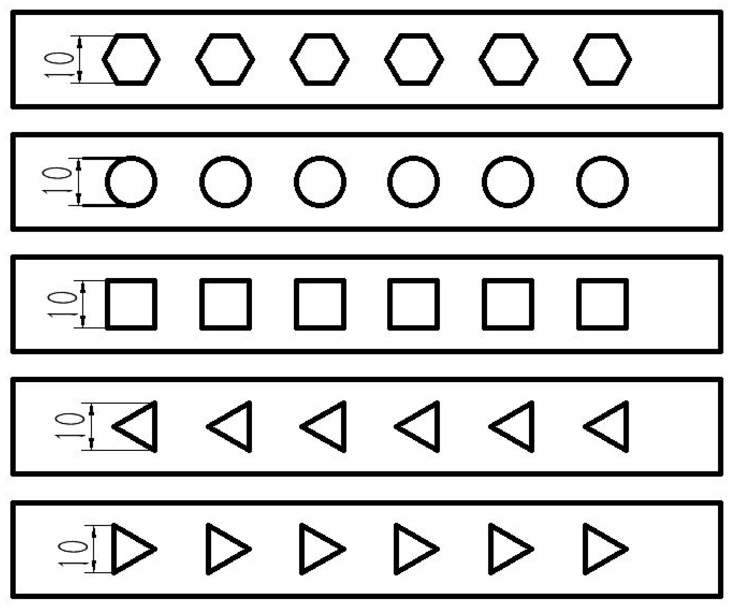
The vortex-inducing structures investigated in this study are illustrated in
Figure 4. All structures share a uniform height of 10 mm and a longitudinal spacing of 20 mm. The detailed cross-sectional geometries are defined as follows:
- (1)
A regular hexagon with an opposite-side distance of 10 mm.
- (2)
A circular cylinder with a diameter of 10 mm.
- (3)
A square prism with a side length of 10 mm.
- (4)
A regular triangular prism with a side length of 10 mm, with the vertex oriented opposite to the coolant flow direction.
- (5)
A regular triangular prism with a side length of 10 mm, with the vertex oriented toward the coolant flow direction.
For convenience of description, these structures are hereafter referred to as the hexagonal, circular, square, reverse-oriented triangular, and forward-oriented triangular vortex-inducing structures, respectively.
Figure 4.
Schematic diagrams of turbulence structures in different shapes.
Figure 4.
Schematic diagrams of turbulence structures in different shapes.
3.1.1. Effect of Vortex-Inducing Structures on Heat Transfer Performance
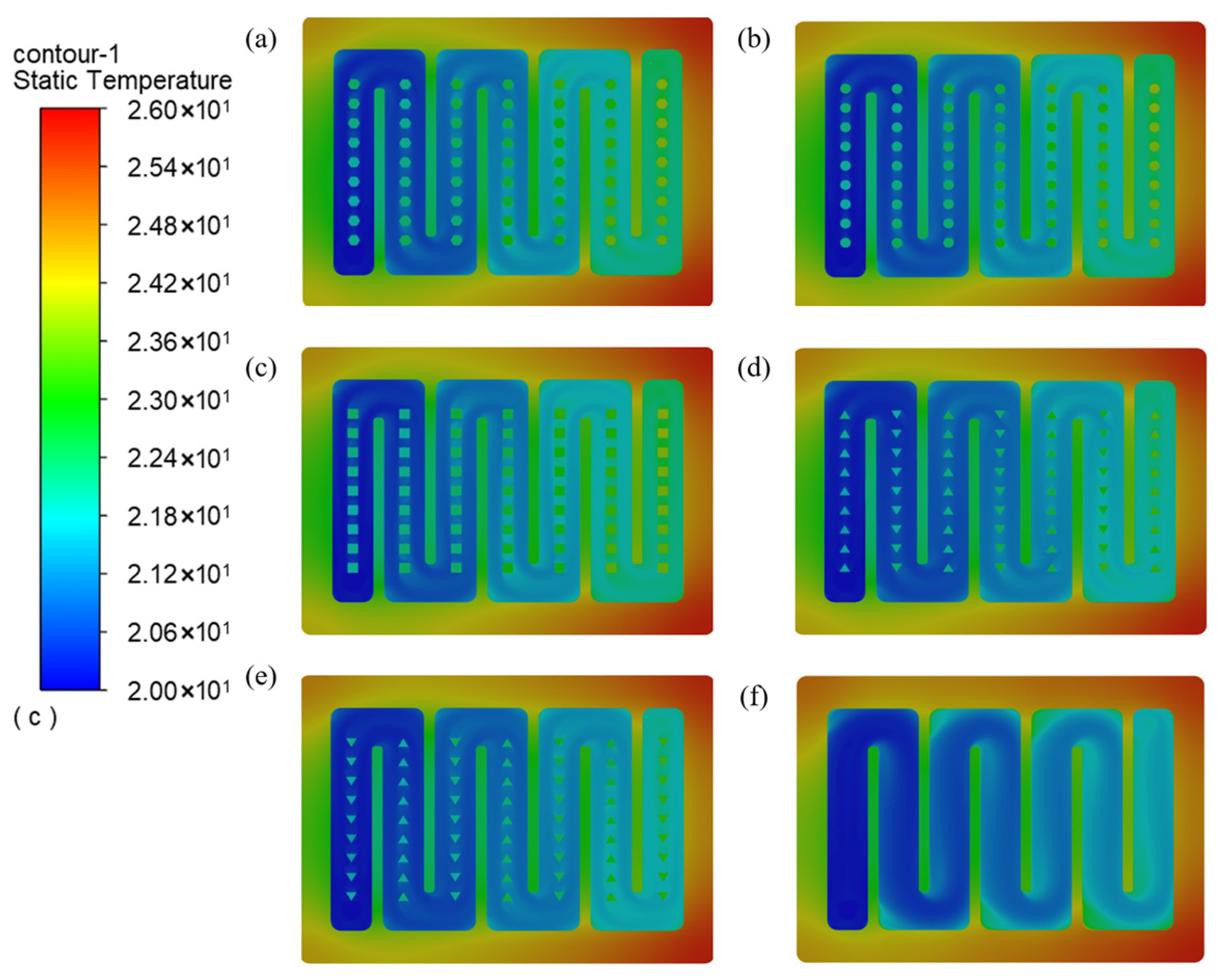
Under an inlet flow rate of 8 L/min, the temperature fields of thermal control plates equipped with different vortex-inducing structures are presented in
Figure 5. Compared with the configuration without vortex-inducing structures, the introduction of vortex-inducing elements leads to an overall increase in coolant temperature within the flow channel, with distinct high-temperature regions forming around the vortex-inducing bodies. This observation indicates that vortex-inducing structures can enhance heat transfer by intensifying fluid disturbance and mixing.
The enhancement effectiveness varies among different geometric configurations. The hexagonal, circular, and square vortex-inducing structures yield higher coolant temperature levels, reflecting stronger heat transfer enhancement, whereas the triangular vortex-inducing structures exhibit comparatively weaker enhancement performance.
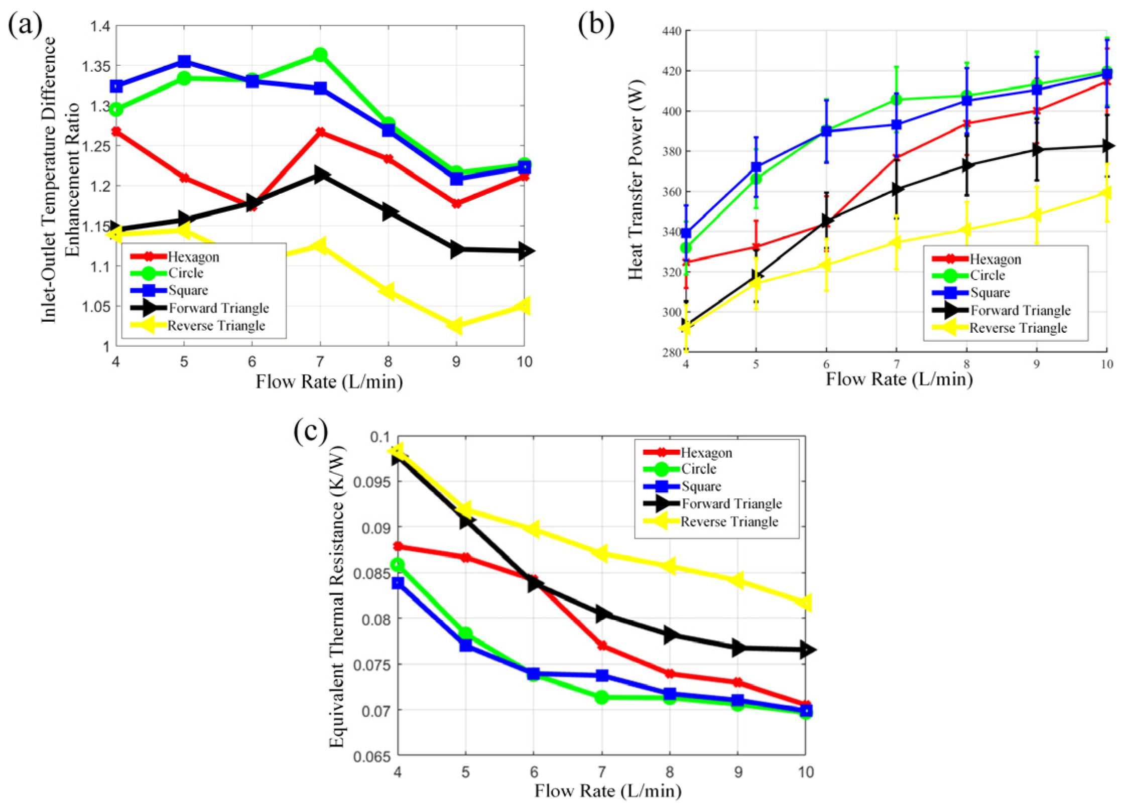
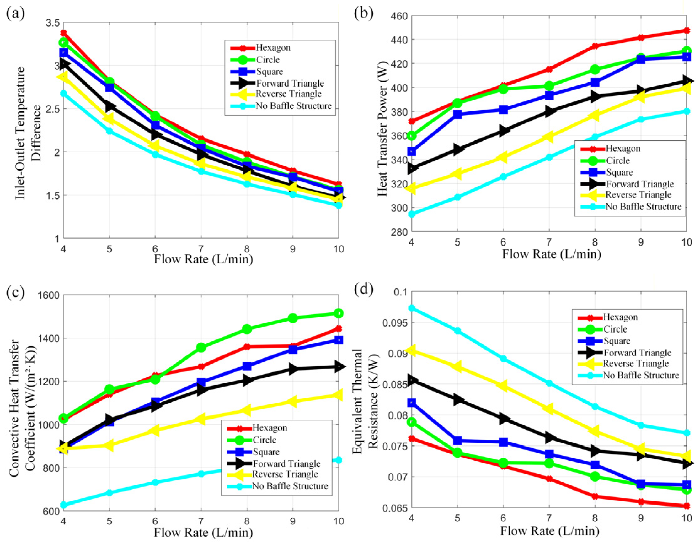
The influence of vortex-inducing structures on the overall heat transfer performance of the thermal control plate is presented in
Figure 6. As the flow rate increases, the inlet–outlet temperature difference of the coolant exhibits a gradual decreasing trend for all configurations. Under identical flow conditions, the introduction of vortex-inducing structures results in an overall increase in the inlet–outlet temperature difference, with the circular and hexagonal structures demonstrating more pronounced enhancement, whereas the reverse-oriented triangular structure shows a relatively limited improvement.
The heat transfer power increases with increasing flow rate for all configurations; however, compared with the thermal control plate without vortex-inducing structures, the relative growth in heat transfer power remains moderate. This behavior is primarily attributed to the fact that the contact thermal resistance between the thermal control plate and the heat source accounts for a substantial proportion of the total thermal resistance. Although increasing flow rate effectively reduces the convective thermal resistance, its contribution to reducing the overall thermal resistance is constrained. At a flow rate of 4 L/min, the heat transfer power of the hexagonal and circular vortex-inducing structures increases by approximately 26% and 25%, respectively, whereas the improvement associated with the reverse-oriented triangular structure is only 7.5%.
Following the introduction of vortex-inducing structures, the average convective heat transfer coefficient increases for all configurations, with the circular structure exhibiting the most significant enhancement. Notably, the improvement in the convective heat transfer coefficient exceeds the corresponding increase in heat transfer power. This discrepancy arises because enhanced convection reduces the wall temperature, thereby decreasing the effective temperature difference between the thermal control plate and the coolant, which in turn limits the growth in heat transfer power.
Analysis of the equivalent thermal resistance indicates that the hexagonal and circular vortex-inducing structures yield lower equivalent thermal resistance, resulting in superior overall heat transfer performance.
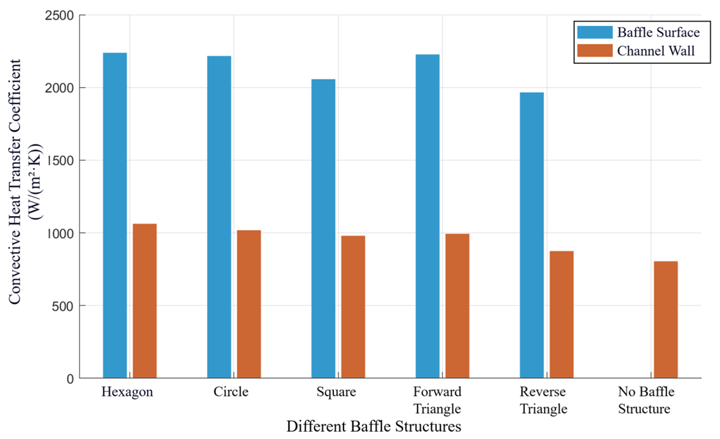
To reveal local heat transfer differences, the distribution of the convective heat transfer coefficient on the flow channel wall and the surface of vortex-inducing structures at a flow rate of 8 L/min is presented in
Figure 7. The convective heat transfer coefficient on the surface of vortex-inducing elements is significantly increased, and the overall heat transfer coefficient along the channel wall is also higher than that of the configuration without vortex-inducing structures, indicating that vortex-inducing structures exert a sustained enhancement effect on near-wall heat transfer. Although the forward-oriented triangular vortex-inducing structure exhibits a relatively high surface convective heat transfer coefficient, its overall heat transfer power improvement remains limited due to the smaller effective heat transfer area.
3.1.2. Flow Characteristics of the Thermal Control Plate
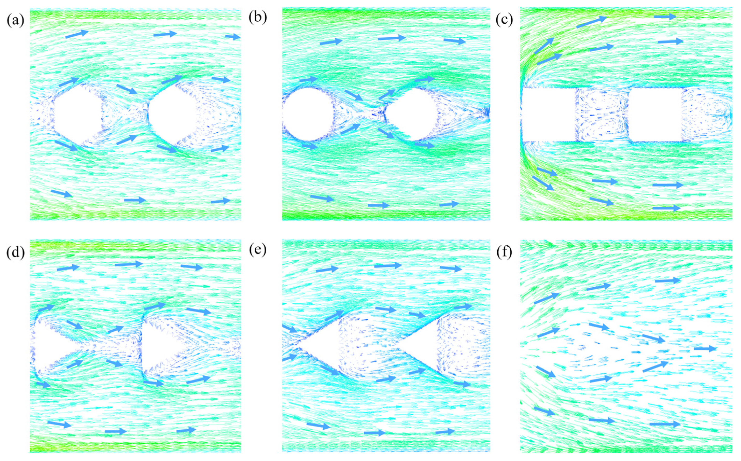
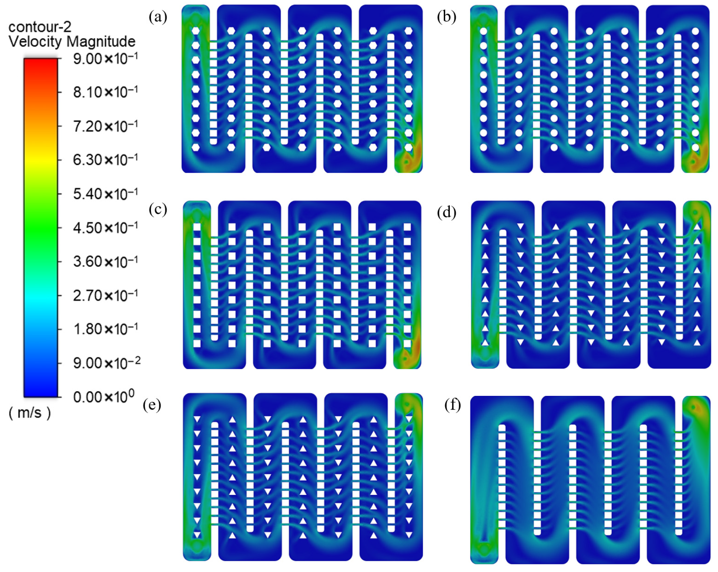
The velocity fields of thermal control plates equipped with different vortex-inducing structures are shown in
Figure 8. Compared with the configuration without vortex-inducing structures, the introduction of vortex-inducing elements leads to an increase in the local flow velocity on both sides of the structures, primarily because the obstruction reduces the local hydraulic diameter and accelerates the main flow. Meanwhile, recirculation zones form between adjacent vortex-inducing elements, mainly as a result of flow separation induced by adverse pressure gradients. The separation behavior exhibits pronounced dependence on geometric shape. The square vortex-inducing structure, characterized by sharp edges and parallel alignment, tends to generate large recirculation regions between neighboring elements and produces the strongest velocity gradients on both sides. The hexagonal and circular structures also induce recirculation; however, the vortical regions are mainly concentrated in the central area between elements. In contrast, the triangular structures exhibit relatively lower overall flow velocities on both sides. The forward-oriented triangular structure induces limited recirculation due to flow impingement at the leading vertex, whereas the reverse-oriented triangular structure allows the flow to slide along the edges, resulting in less pronounced recirculation.
Turbulence intensity (TI) describes the magnitude of velocity fluctuations in a turbulent flow field. It is defined as the ratio of the root-mean-square of the velocity fluctuations to the mean flow velocity and can be expressed as Equations (5)–(7):
In these equations, u′ represents the root-mean-square value of the velocity fluctuations, and U denotes the mean velocity of the coolant. The terms , , represent the velocity fluctuations in the x-, -, and -directions, respectively, while ux, uy, uz denote the corresponding mean velocity components (m/s).
Turbulence intensity plays an important role in determining the heat transfer and flow characteristics of the thermal control plate and is therefore a key parameter in the design of thermal control systems.
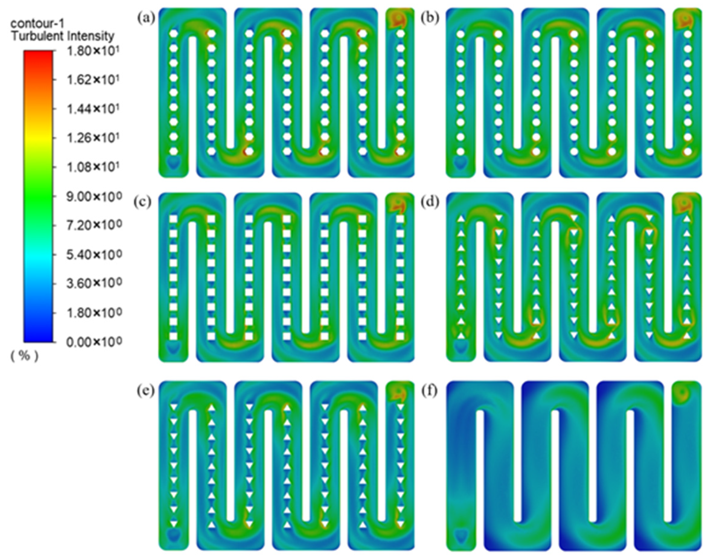
The distribution of TI is illustrated in
Figure 9. The introduction of vortex-inducing structures leads to a significant increase in TI compared with the case without vortex structures, indicating enhanced flow disturbance and fluid mixing. In particular, the previously existing low-turbulence regions at channel bends are effectively suppressed.
A clear dependence of turbulence intensity on the geometry of vortex-inducing structures can be observed. The hexagonal and circular configurations exhibit the strongest turbulence enhancement, followed by the square structure, while the triangular configurations—especially the reverse-oriented triangular structure—show relatively weaker turbulence intensification and retain more low-TI regions between adjacent elements.
Moreover, regions of high turbulence intensity are mainly concentrated near the vortex-inducing structures and at channel bends, demonstrating that both geometric disturbance and flow redirection contribute to the local enhancement of turbulence.
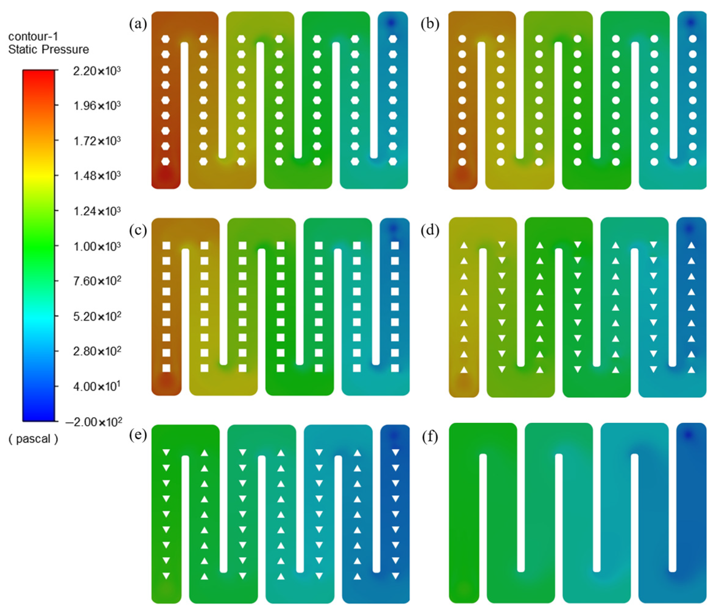
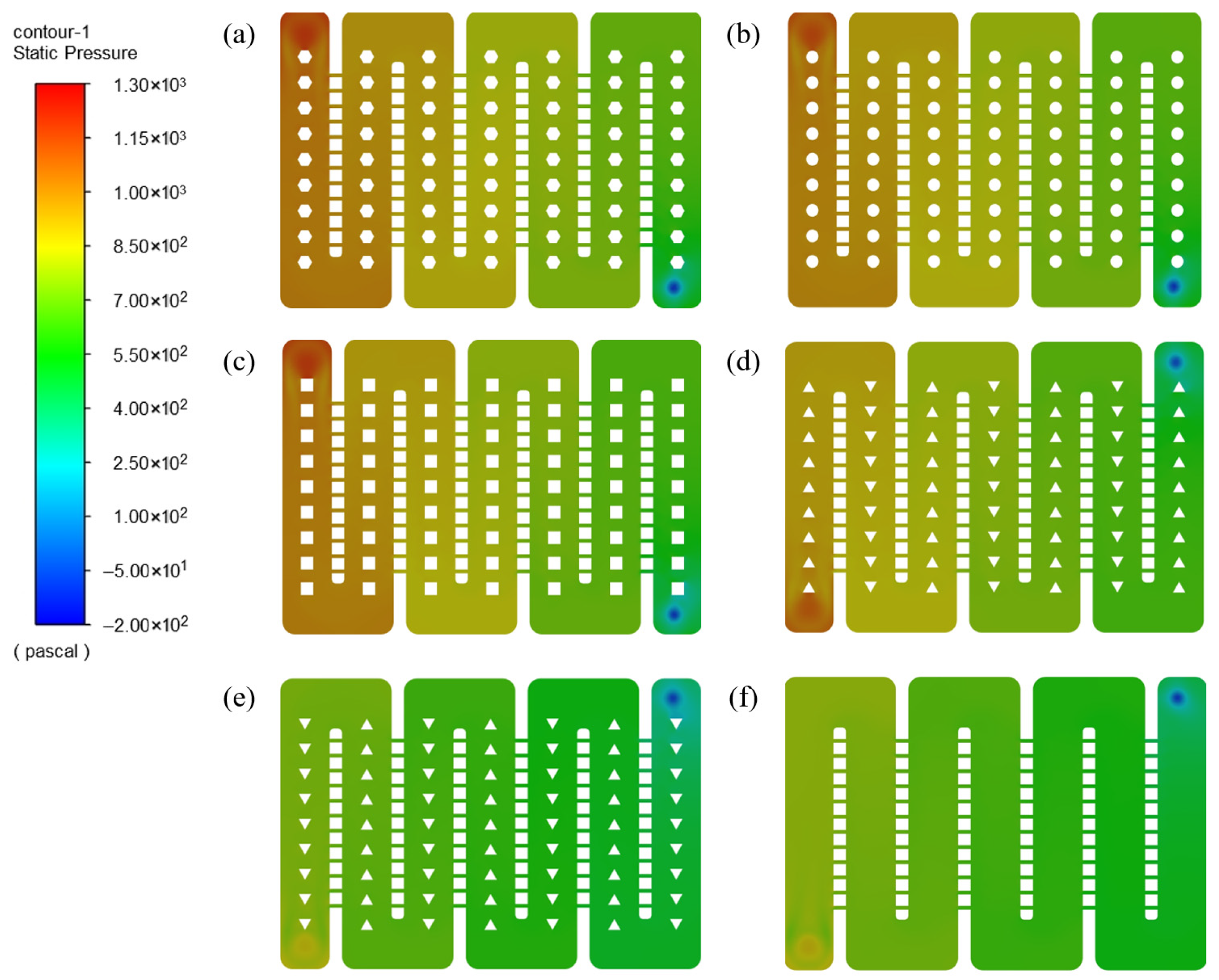
The pressure field distribution is presented in
Figure 10. The introduction of vortex-inducing structures generally leads to an increase in pressure drop, with the hexagonal, circular, and square configurations exhibiting more pronounced rises, whereas the triangular structures show relatively smaller variations. Moreover, the forward-oriented triangular vortex-inducing structure produces a higher pressure drop than the reverse-oriented triangular configuration. Combined with the velocity vector field, it can be observed that configurations associated with larger pressure drops are typically accompanied by more extensive wake regions and recirculation zones, indicating a higher flow resistance penalty.
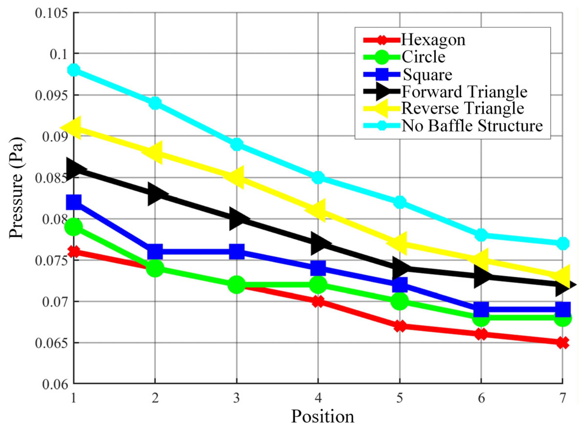
The pressure distribution along the flow direction is presented in
Figure 11. For all configurations, the pressure gradually decreases from the inlet to the outlet, indicating the cumulative effect of flow resistance along the channel. Compared with the case without vortex-inducing structures, all configurations incorporating vortex elements exhibit lower pressure drops, suggesting that the introduction of vortex-inducing structures can effectively regulate the flow field and reduce excessive hydraulic losses under the present operating conditions.
Among the investigated geometries, the hexagonal vortex-inducing structure results in the lowest pressure drop, followed by the circular and square configurations. In contrast, the triangular structures, particularly the reverse-oriented triangular configuration, produce relatively higher pressure drops among all vortex-inducing cases. This behavior can be attributed to the stronger flow obstruction and more pronounced flow separation induced by the triangular geometry, especially in the reverse arrangement, which leads to increased energy dissipation. Overall, the results indicate that the geometry of vortex-inducing structures plays a crucial role in determining the pressure-drop characteristics, and appropriate geometric design is essential for achieving a balance between flow regulation and hydraulic performance.
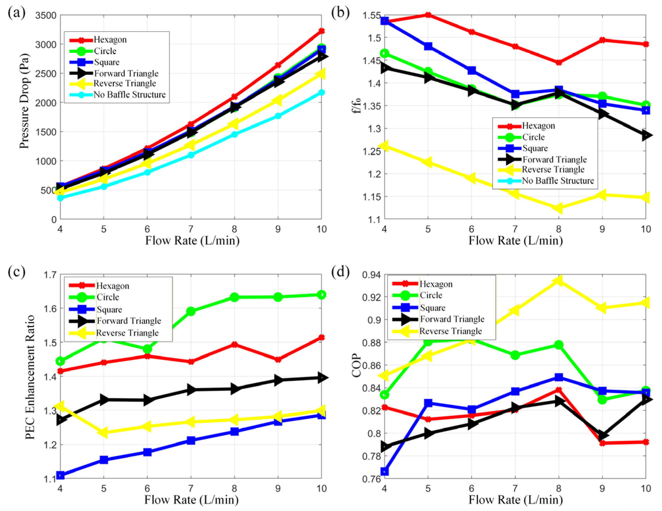
The comprehensive performance results are presented in
Figure 12. As the flow rate increases, the pressure drop rises while the friction factor decreases for all configurations. Among the investigated geometries, the hexagonal vortex-inducing structure exhibits the largest pressure drop, whereas the reverse-oriented triangular structure shows a relatively smaller increase.
Compared with the configuration without vortex-inducing structures, all vortex-inducing designs lead to higher pressure drop; however, the PEC is consistently improved, indicating an overall enhancement in comprehensive heat transfer capability. The circular vortex-inducing structure achieves the most pronounced PEC improvement, followed by the hexagonal and square structures, while the triangular configurations demonstrate the weakest enhancement.
Meanwhile, COP decreases by approximately 10–25%, reflecting the additional pumping power penalty associated with vortex-induced enhancement. From an integrated perspective, the circular vortex-inducing structure exhibits the most balanced performance between heat transfer gain and energy consumption cost. At a flow rate of 4 L/min, it achieves an approximate 25% increase in heat transfer power, while the COP decreases by only about 15%.
3.2. Effect of a Single Microchannel Structure on the Comprehensive Performance of the Thermal Control Plate
To facilitate a comparative evaluation of the heat transfer enhancement effect of microchannel structures, microchannels are introduced into a thermal control plate with a flow channel cross-section of 40 mm in width and 12 mm in height. Considering manufacturability constraints, the microchannel size cannot be excessively small, while overly large microchannels may adversely affect coolant flow behavior. Accordingly, the following microchannel configurations are investigated:
- (1)
Microchannel size of 2 mm, with 12 microchannels per fin.
- (2)
Microchannel size of 3 mm, with 12 microchannels per fin.
- (3)
Microchannel size of 4 mm, with 12 microchannels per fin.
- (4)
Microchannel size of 3 mm, with 6 microchannels per fin.
- (5)
Microchannel size of 3 mm, with 8 microchannels per fin.
- (6)
Microchannel size of 3 mm, with 10 microchannels per fin.
The boundary conditions used in the microchannel simulations are defined as follows:
A velocity inlet boundary condition was applied at the inlet with a velocity of 0.5878 m/s, perpendicular to the inlet surface. The inlet turbulence intensity was set to 5%, with a hydraulic diameter of 0.019 m, and the inlet temperature was fixed at 293.15 K. A constant temperature boundary condition of 323.15 K was applied to the heating surface to represent the heat source. The equivalent wall thickness was set to 1.36 m according to the equivalent thermal contact resistance. The outlet was defined as a pressure outlet. Other external walls were maintained at a constant temperature of 300 K, and their thickness was neglected in the simulation.
3.2.1. Effect of Microchannel Dimensions on Comprehensive Performance
(1) Heat Transfer Performance of the Thermal Control Plate
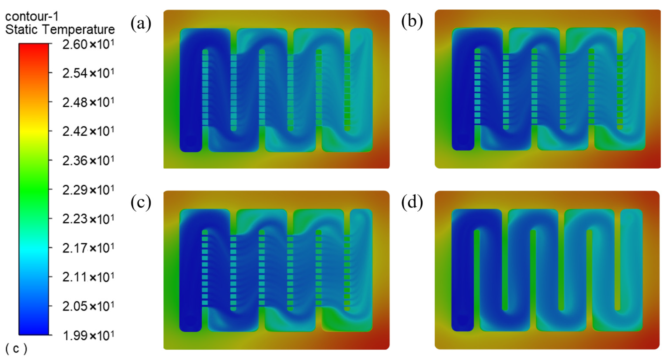
The temperature fields of thermal control plates with different microchannel sizes are shown in
Figure 13. After introducing microchannels, the overall coolant temperature increases, and coolant from low-temperature regions is redistributed through the microchannels to merge with high-temperature regions, thereby modifying the temperature distribution in these zones. In addition, supplementary heat transfer within the microchannels reduces the fin temperature, indicating enhanced local heat dissipation.
However, localized high-temperature regions persist near the channel bends, and these temperature dead zones become more pronounced as microchannel size increases, leading to reduced temperature uniformity within the flow channel.
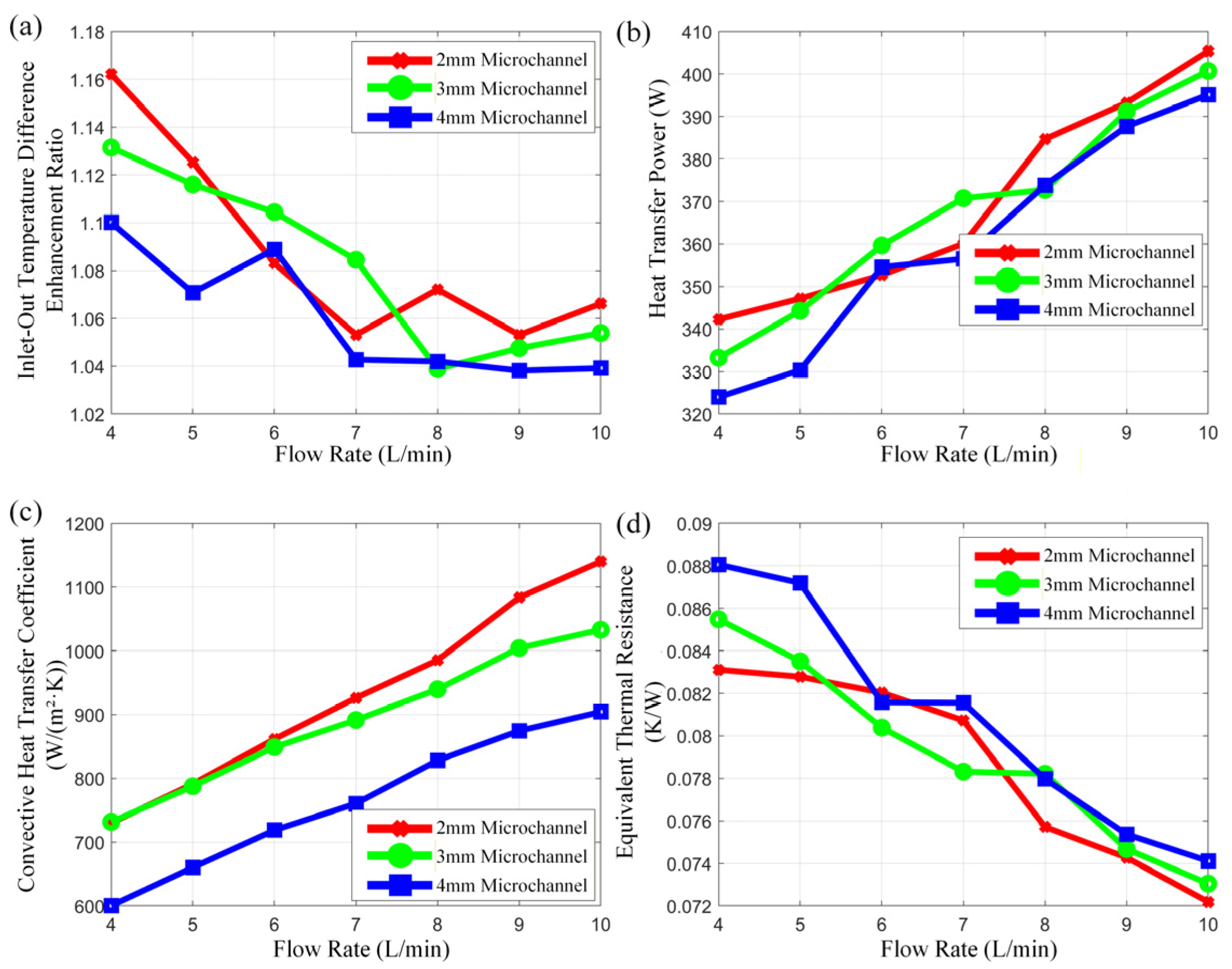
The performance comparison results are presented in
Figure 14. As the flow rate increases, the inlet–outlet temperature difference decreases, while the heat transfer power increases; however, the increment in temperature difference gradually diminishes at higher flow rates. The introduction of microchannels enhances heat transfer performance to a certain extent, but increasing microchannel size weakens the enhancement effect. Among the investigated configurations, the 2 mm microchannel exhibits the most pronounced improvement, achieving an approximately 16% increase in heat transfer power at a flow rate of 4 L/min. The convective heat transfer coefficient increases with flow rate; however, at a given flow rate, it decreases as microchannel size increases. This trend is primarily attributed to flow redistribution, which reduces the main-channel velocity and Reynolds number, thereby weakening convective heat transfer intensity. The equivalent thermal resistance shows an overall reduction after introducing microchannels but increases with increasing microchannel size, indicating that within the investigated range, smaller microchannels are more favorable for enhancing the heat transfer capability of the thermal control plate.
(2) Flow Characteristics of the Thermal Control Plate
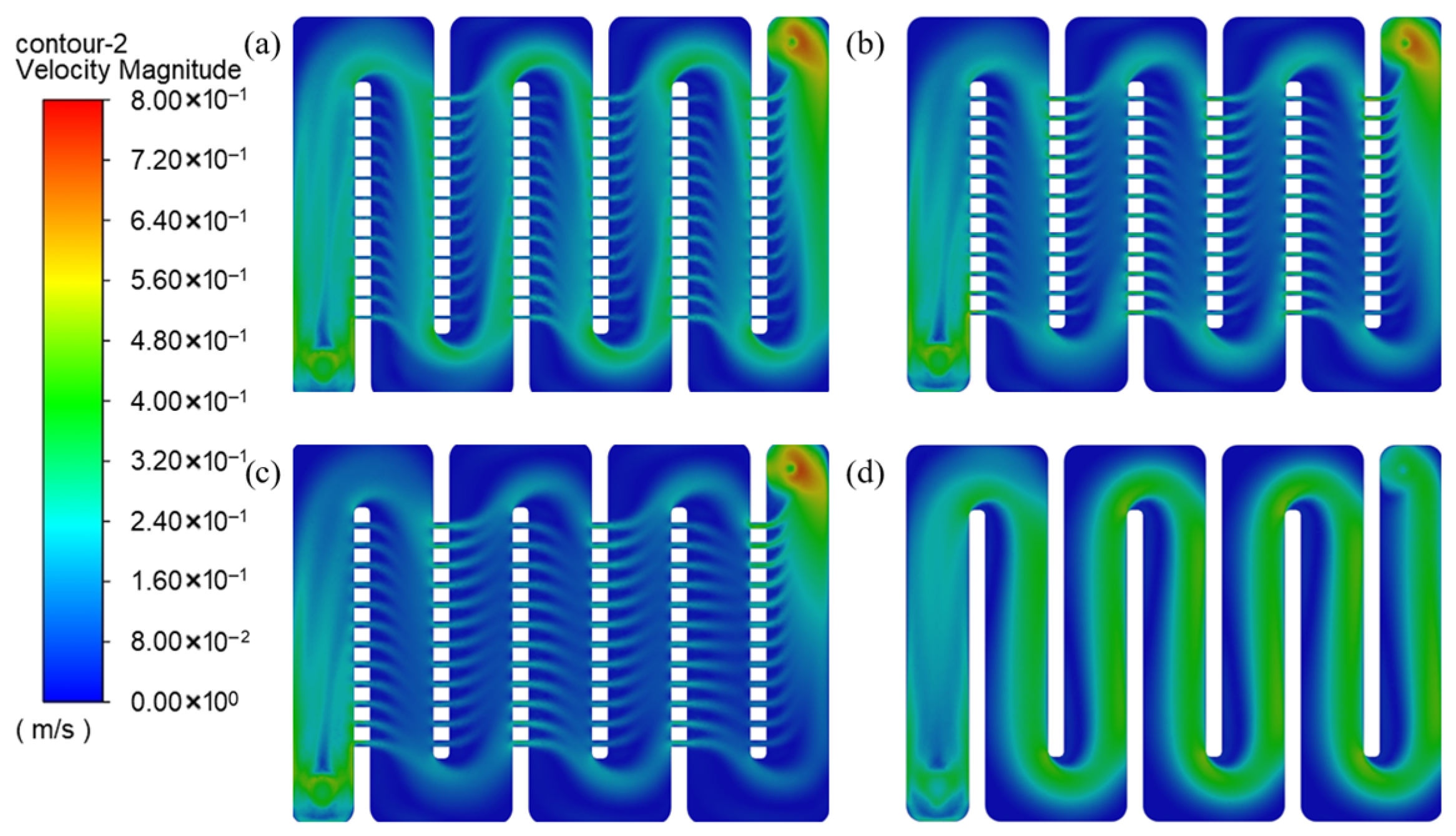
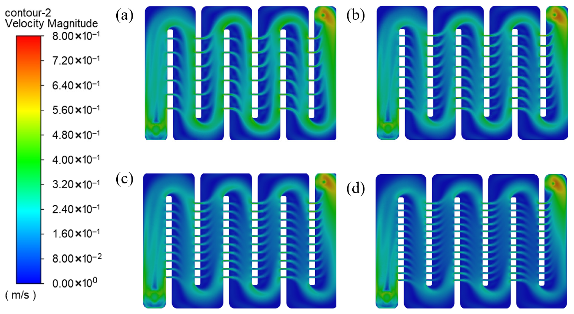
Figure 15 shows the velocity distribution of different thermal control plates under the same flow rate. It can be observed that after introducing microchannels, the average velocity in the main flow channel decreases overall, and the flow velocity further decreases with increasing microchannel size. Low-velocity regions appear near the channel bends, exhibiting a tendency to form stagnation zones. In contrast, high-velocity regions are mainly concentrated near the microchannels and the inlet/outlet sections, indicating that microchannels primarily redistribute the velocity field within the flow channel, while exerting a limited influence on the inlet and outlet flow conditions. This flow redistribution contributes to reduced local Reynolds numbers in the main channel, thereby influencing convective heat transfer intensity and overall flow uniformity.
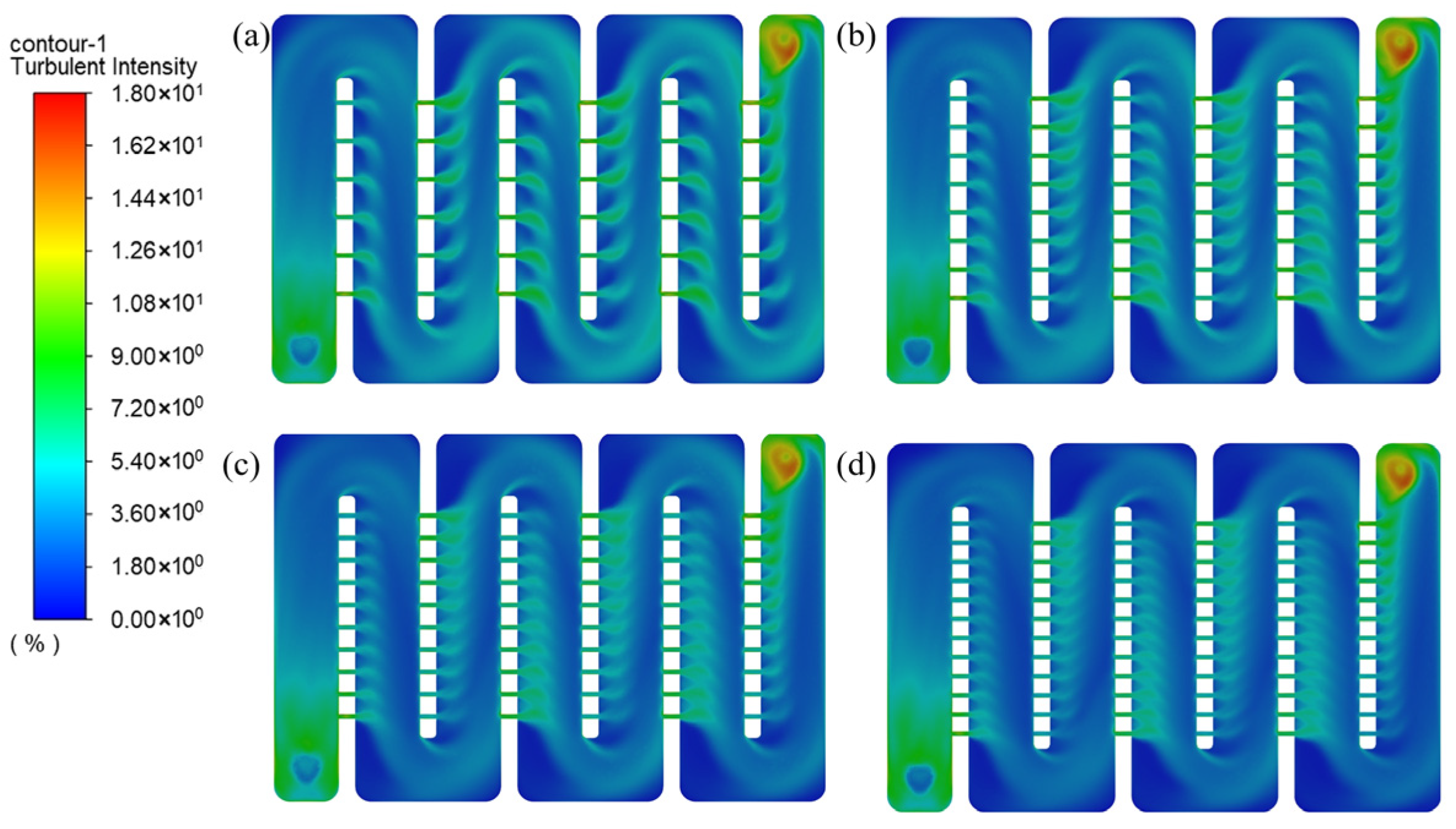
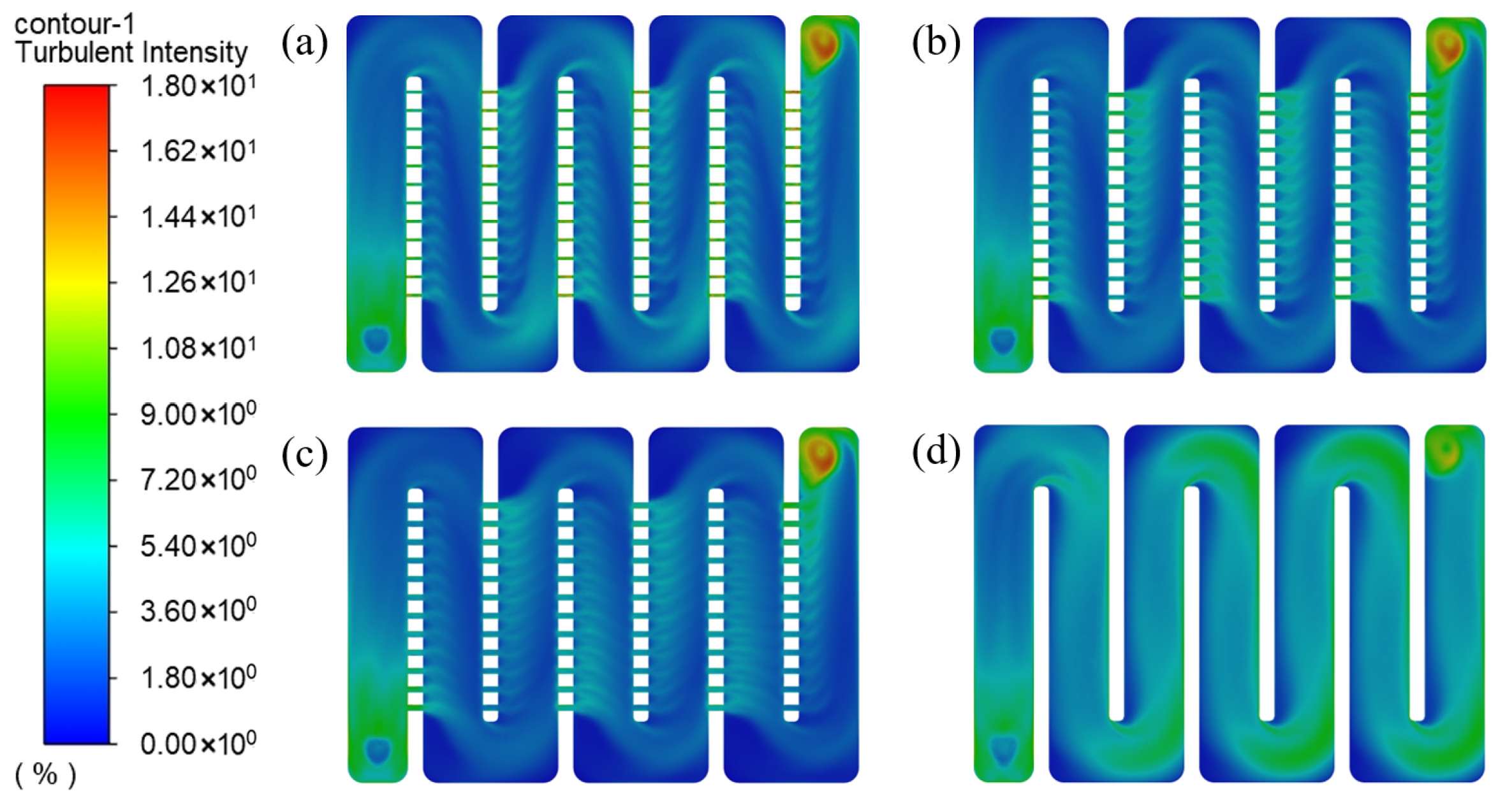
Figure 16 presents the TI distributions for thermal control plates with different microchannel sizes. In the configuration without microchannels, the overall TI is relatively high; after introducing microchannels, the TI decreases significantly, which may weaken heat transfer but is beneficial for reducing pressure drop. Relatively high TI is observed in the confluence regions between the main channel and branch channels, and this intensity slightly increases with increasing microchannel size. Outside the confluence zones, however, larger microchannel sizes lead to a noticeable reduction in TI, and the distributions for the 3 mm and 4 mm microchannels exhibit relatively small differences, resulting in a more uniform overall turbulence field.
Figure 17 presents the pressure field contours of different thermal control plates under the same flow rate. It can be observed that the introduction of microchannels significantly alters the pressure distribution. As the microchannel size increases, the pressure drop gradient within the flow channel decreases, and the inlet–outlet pressure drop is markedly reduced, indicating that microchannels can effectively suppress inlet and outlet pressure losses. However, even for the 4 mm microchannel configuration, although the pressure drop inside the channel is relatively small, a substantial pressure drop still exists at the inlet and outlet, suggesting that cross-sectional area variations constitute the dominant source of flow resistance; consequently, further increasing microchannel size yields diminishing marginal benefits in pressure reduction.
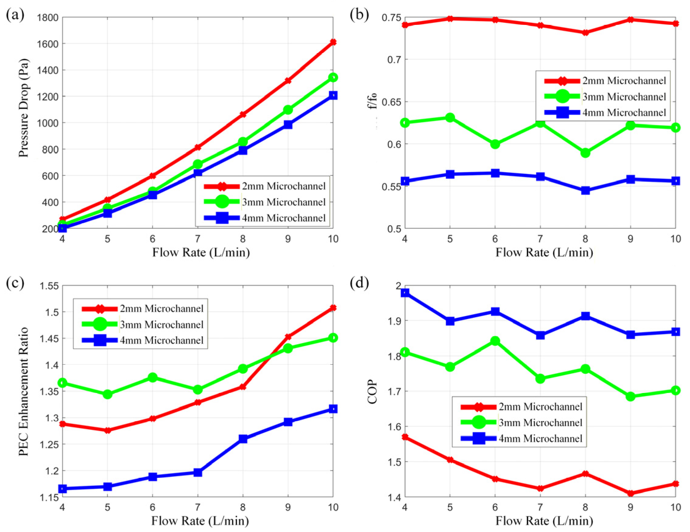
Figure 18 summarizes the inlet–outlet pressure drop extracted from simulations, as well as the calculated friction factor, PEC, and COP. As the flow rate increases, the pressure drop rises while the friction factor decreases for all configurations. Larger microchannel sizes result in lower pressure drops and friction factors, with the 4 mm microchannel achieving an approximately 45% reduction in friction factor, indicating a substantial improvement in flow characteristics. After introducing microchannels, both PEC and COP exhibit significant enhancement: the 3 mm microchannel configuration provides the largest PEC improvement, while the 4 mm microchannel configuration achieves the highest COP enhancement, though its advantage over the 3 mm configuration remains limited. Considering heat transfer power and flow uniformity simultaneously, the 3 mm microchannel configuration demonstrates the most favorable comprehensive performance.
3.2.2. Effect of Microchannel Number on Comprehensive Performance
(1) Heat Transfer Performance of the Thermal Control Plate
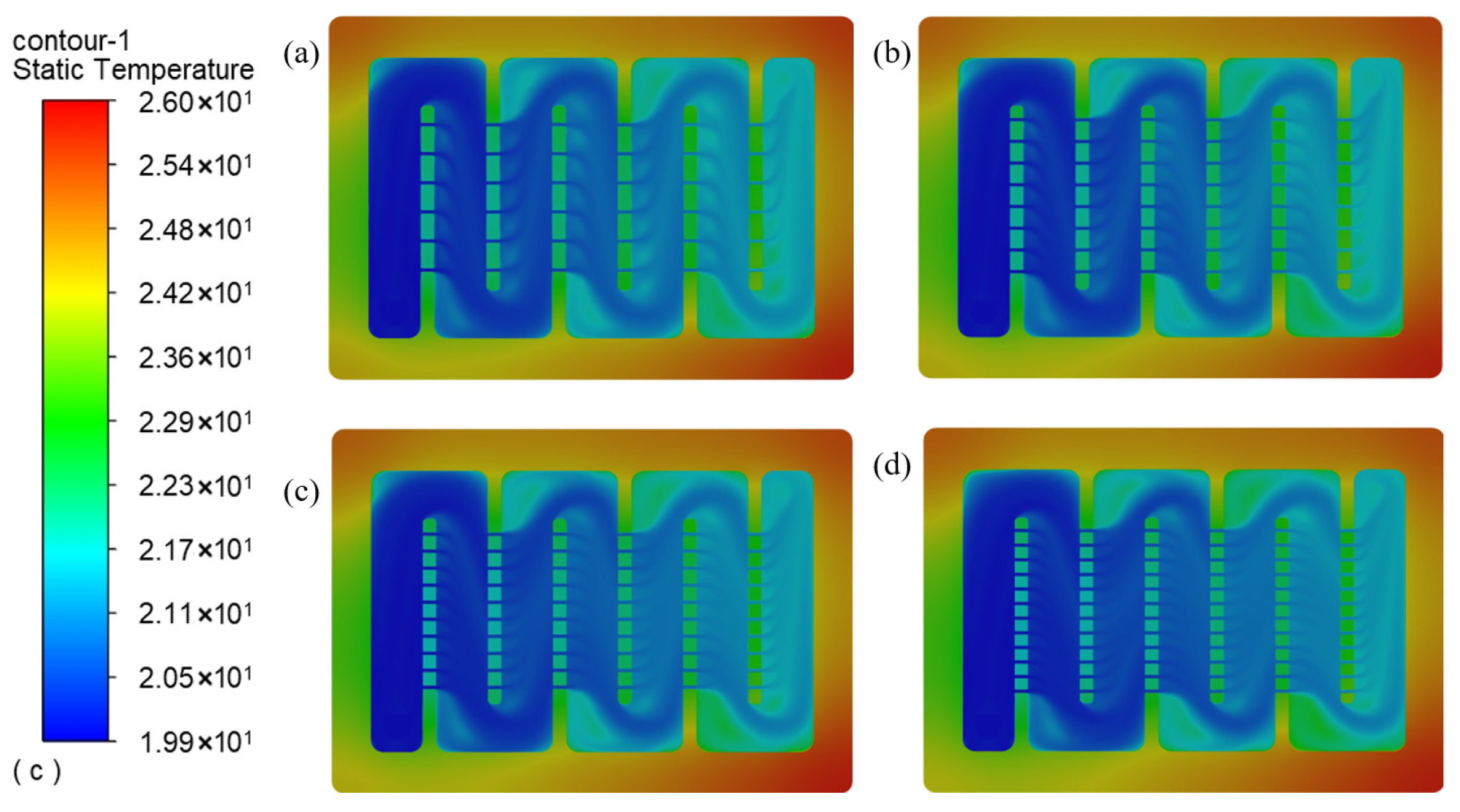
Figure 19 presents the temperature field contours of thermal control plates with different numbers of microchannels. As the number of microchannels increases, the overall coolant temperature within the flow channel rises, and more pronounced high-temperature dead zones emerge near the channel bends, which is unfavorable for sustained heat transfer. Meanwhile, the coolant temperature in the vicinity of the microchannels decreases with increasing microchannel number, resulting in an increased temperature gradient between the coolant and the channel wall, thereby enhancing local heat transfer performance in these regions.
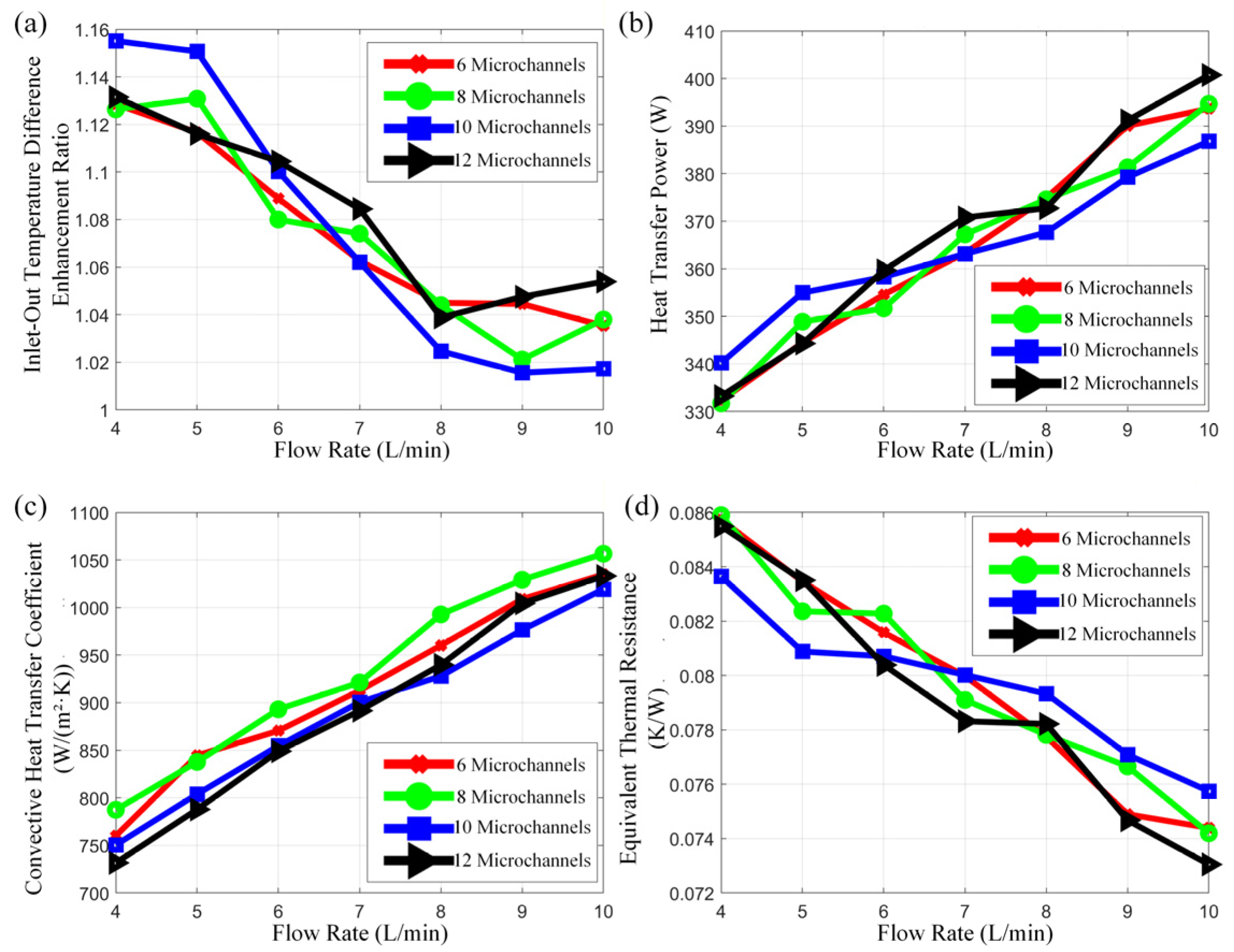
Figure 20 presents the inlet–outlet temperature difference, heat transfer power, average convective heat transfer coefficient, and equivalent thermal resistance of thermal control plates with different numbers of microchannels, as extracted from the numerical simulations. As shown in
Figure 20a,b, the enhancement in inlet–outlet temperature difference induced by microchannels is more pronounced under low flow rate conditions, whereas the improvement becomes relatively limited at higher flow rates. The differences in heat transfer power among configurations with varying microchannel numbers are relatively small; however, the configuration with 12 microchannels consistently exhibits higher heat transfer power across all operating conditions.
As illustrated in
Figure 20c, the introduction of microchannels leads to an increase in the average convective heat transfer coefficient, primarily due to the enhanced flow disturbance induced by microchannels. With increasing microchannel number, the convective heat transfer coefficient exhibits a non-monotonic trend, first increasing and then decreasing, reaching its maximum value at eight microchannels. Since increasing the number of microchannels simultaneously expands the effective heat transfer area, the variation trend of heat transfer power does not fully coincide with that of the convective heat transfer coefficient.
As shown in
Figure 20d, all microchannel configurations yield a lower equivalent thermal resistance compared with the configuration without microchannels. Overall, the configuration with 12 microchannels demonstrates the smallest equivalent thermal resistance, indicating a more favorable heat transfer performance.
(2) Flow Characteristics of the Thermal Control Plate
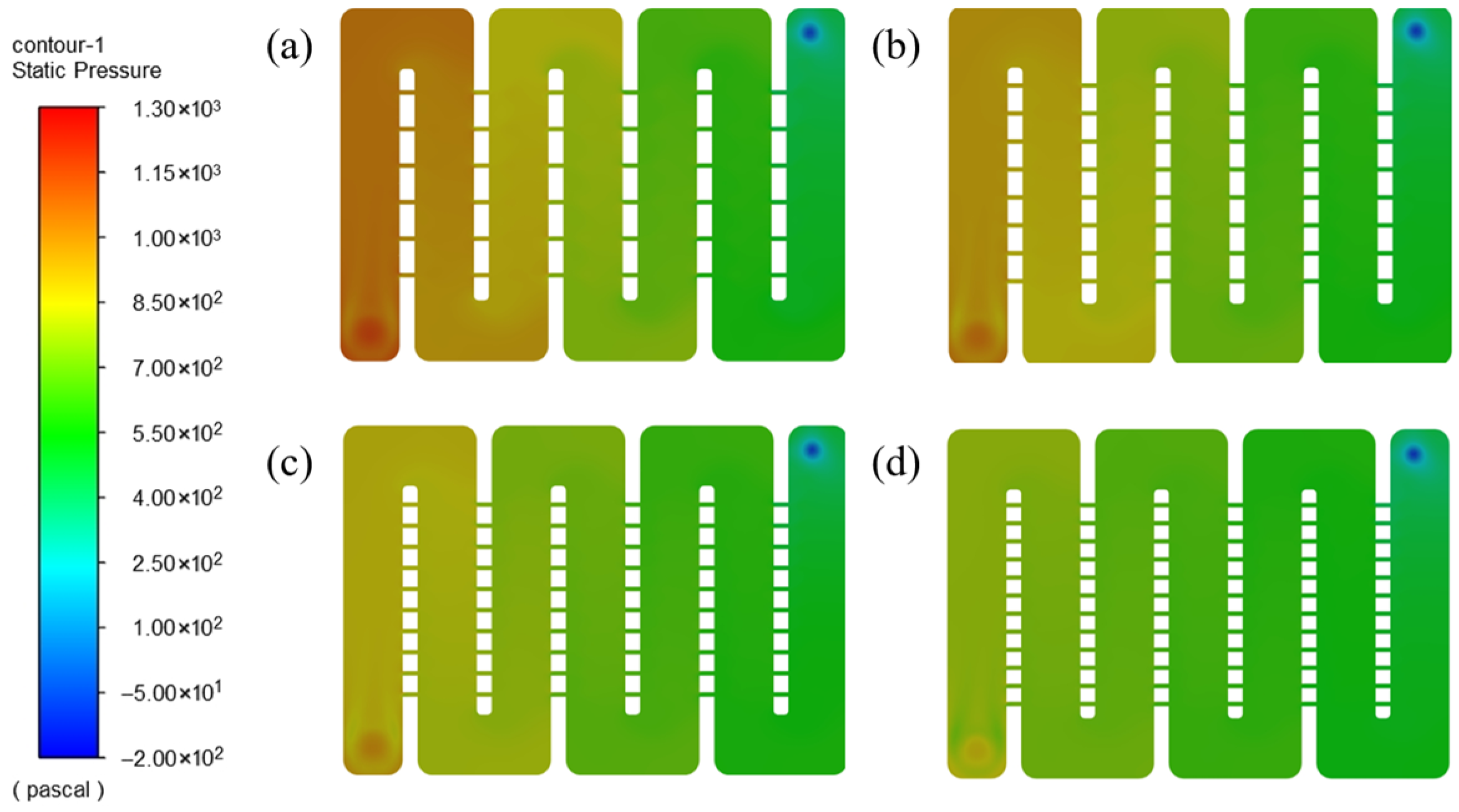
Figure 21 illustrates the pressure field contours of the coolant in thermal control plates with different numbers of microchannels. It can be observed that as the number of microchannels increases, the pressure drop within the flow channel gradually decreases, and the pressure distribution becomes more uniform, with no pronounced pressure loss occurring at channel bends. This behavior is primarily attributed to the reduction in coolant velocity within the main flow channel, which mitigates pressure losses along the flow path. Overall, increasing the microchannel number exhibits a significant suppressive effect on the pressure drop of the thermal control plate.
A comparison between
Figure 21 and
Figure 17 further indicates that increasing microchannel size is more effective in reducing pressure drop than increasing the number of microchannels, highlighting the dominant influence of microchannel size on flow resistance control.
Figure 22 presents the velocity field contours of the coolant. It can be observed that as the number of microchannels increases, the coolant velocity within the flow channel gradually decreases, while high-velocity regions are mainly concentrated in the vicinity of the microchannels, and the coolant velocity near channel bends remains relatively low. When the number of microchannels is six, the velocity field distribution is relatively similar to that of the configuration without microchannels; however, with a further increase in microchannel number, the coolant velocity in the main flow channel progressively decreases, indicating an increasingly pronounced flow redistribution effect.
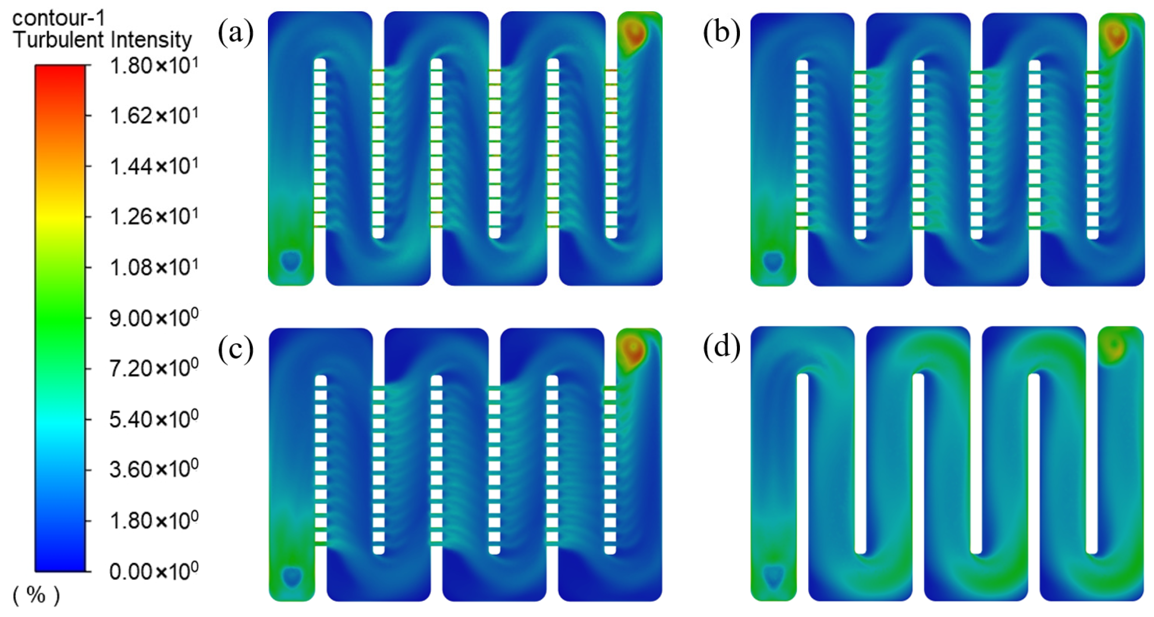
Figure 23 presents the TI contours of the coolant within the thermal control plate. For all investigated configurations, regions of high TI are primarily concentrated near the inlet/outlet sections and in the vicinity of the microchannels. The overall differences in TI among the various structures are relatively small. As the number of microchannels increases, the low-turbulence regions between adjacent microchannels gradually diminish, and the TI distribution in the confluence region between the main channel and branch channels becomes more uniform, indicating improved flow mixing characteristics.
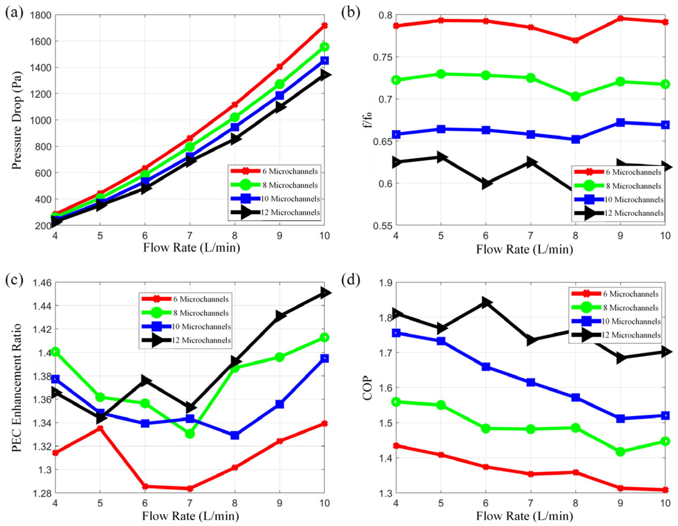
Figure 24 summarizes the variations in inlet–outlet pressure drop, friction factor, PEC, and COP of the thermal control plate, as extracted from the simulation results. As shown in
Figure 24a,b, both the inlet–outlet pressure drop and the friction factor exhibit a gradual decreasing trend with increasing microchannel number. When the number of microchannels reaches 12, the friction factor is reduced by approximately 36–42% compared with the conventional thermal control plate, indicating that increasing microchannel number can effectively mitigate flow resistance and significantly improve flow characteristics.
As illustrated in
Figure 24c, the PEC demonstrates an overall increasing trend with increasing microchannel number. After introducing 12 microchannels, the PEC improvement reaches approximately 30–50%, suggesting that a larger number of microchannels is beneficial for the simultaneous enhancement of heat transfer and flow performance. As shown in
Figure 24d, the COP also increases with microchannel number, with a more pronounced improvement under low-flow conditions. This behavior is mainly attributed to the fact that, as the flow rate increases, the relative enhancement in heat transfer power gradually weakens, whereas the variation in pressure drop ratio remains relatively limited. Although the COP improvement becomes less significant under high-flow conditions, all microchannel configurations still achieve a COP enhancement exceeding 30% compared with the conventional thermal control plate; among them, the configuration with 12 microchannels attains a maximum COP improvement of approximately 85%.
To further interpret the observed performance trends, a detailed mechanism analysis is provided in
Section 3.3.
3.3. Mechanism Analysis of Performance Variation
To further clarify the variation trends observed in the simulation results, the underlying mechanisms associated with vortex-inducing structures and microchannel configurations are analyzed in this section.
For vortex-inducing structures, the enhancement in heat transfer mainly originates from the disruption of the thermal boundary layer and the intensification of fluid mixing induced by flow separation and reattachment. These effects significantly increase the convective heat transfer coefficient and the effective heat transfer area. However, the enhanced disturbance is accompanied by increased fluid collision, shear stress, and vortex dissipation, resulting in higher flow resistance and pumping power consumption.
The performance differences among various vortex-inducing geometries are determined by the balance between heat transfer enhancement and hydraulic penalty. Circular structures generate relatively regular vortices, enabling efficient boundary-layer disruption while avoiding excessive resistance caused by sharp edges, thus achieving superior comprehensive performance. In contrast, hexagonal structures, although providing strong heat transfer enhancement, induce greater flow resistance due to their larger frontal area and increased flow path complexity. Triangular structures exhibit weaker boundary-layer disruption, leading to limited heat transfer improvement and inferior overall performance.
For microchannel configurations, the underlying mechanism is associated with flow redistribution and heat transfer compensation. The introduction of microchannels alters the flow distribution within the channel. Larger microchannels enhance flow diversion, reducing the flow rate and Reynolds number in the main channel, which tends to weaken convective heat transfer and decrease pressure drop. However, smaller microchannels, owing to their high surface-area-to-volume ratio and intensified local disturbances, effectively compensate for the reduced flow rate by enhancing boundary-layer disruption. This compensatory mechanism allows the system to achieve improved heat transfer performance while maintaining a reasonable pressure drop.
Overall, the observed performance trends are governed by the competition and balance between heat transfer enhancement and flow resistance increase, which jointly determine the comprehensive thermal–hydraulic performance of the system.
4. Simulation of Composite Structures: Synergistic Mechanism and Performance Enhancement of Vortex-Inducing–Microchannel Designs
In
Section 3, the effects of introducing vortex-inducing structures and microchannel structures on the comprehensive heat transfer performance of the thermal control plate were investigated separately. This section focuses on the combined heat transfer performance of vortex-inducing and microchannel structures. As demonstrated in
Section 3.1 and
Section 3.2, both enhancement strategies improve the overall performance of the thermal control plate to a certain extent. Specifically, vortex-inducing structures enhance coolant flow uniformity and increase heat transfer power, but at the cost of higher inlet–outlet pressure drop, whereas microchannels effectively reduce pressure drop but provide limited heat transfer enhancement and may deteriorate flow uniformity.
In this section, a flow plate with microchannels of 3 mm in size and 12 channels per fin is combined with the vortex-inducing structures investigated in
Section 3.1. Numerical simulations are conducted for multiple vortex-inducing–microchannel composite configurations to evaluate their heat transfer and flow performance.
(1) Heat Transfer Performance of the Thermal Control Plate
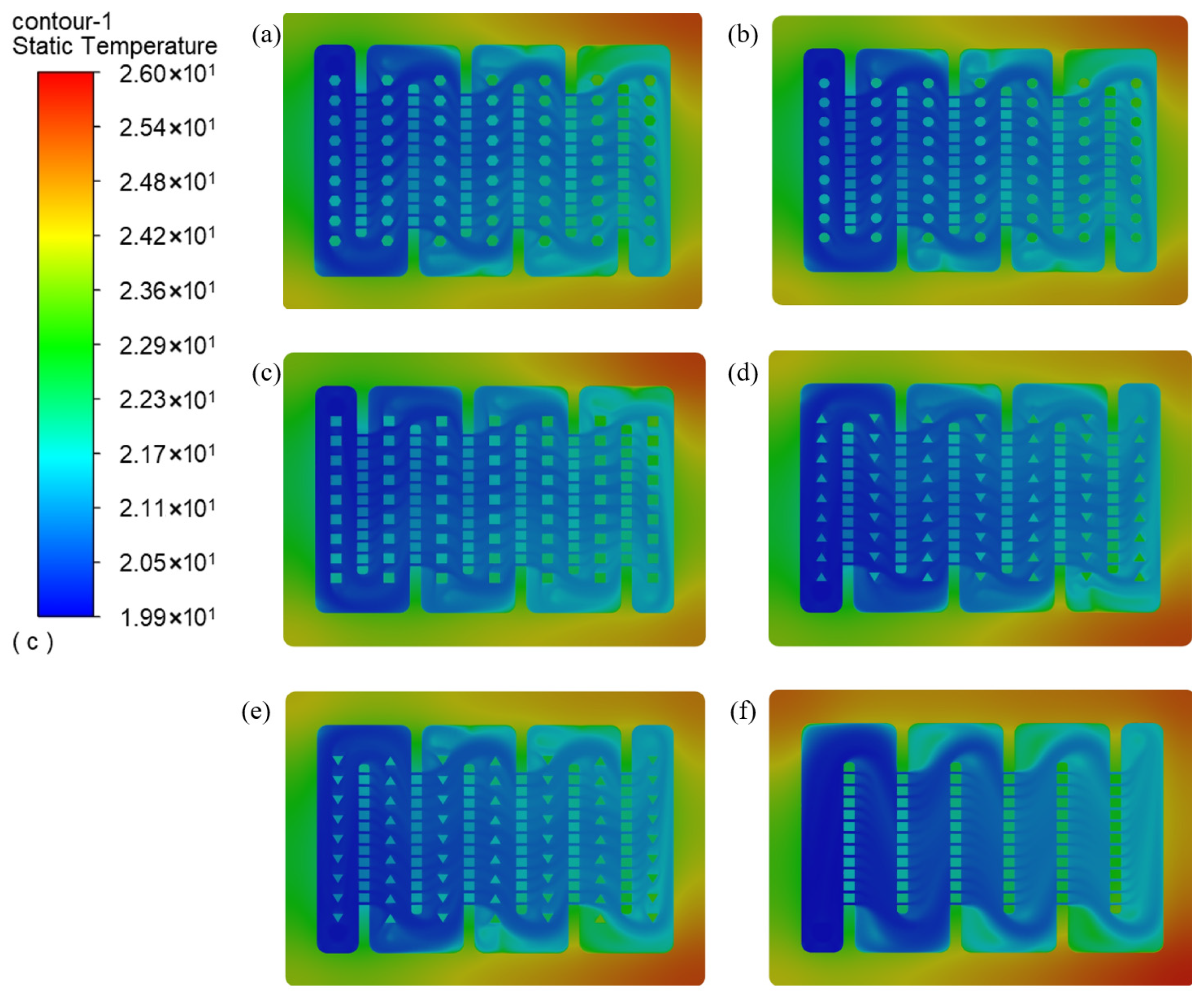
Figure 25 presents the temperature field contours of a microchannel thermal control plate without vortex-inducing structures and several vortex-inducing–microchannel composite thermal control plates. Compared with the microchannel plate without vortex-inducing structures, the introduction of vortex-inducing elements mitigates the formation of temperature dead zones at channel bends. In the non-vortex microchannel configuration, a temperature dead zone appears at the first channel bend; in the reverse-oriented triangular configuration, dead zones begin to emerge in the mid-section of the flow channel; in the hexagonal, circular, and forward-oriented triangular configurations, dead zones are primarily observed near the downstream end of the channel. In contrast, the square vortex-inducing structure exhibits negligible temperature dead zones, indicating its superior capability in alleviating flow non-uniformity induced by microchannels.
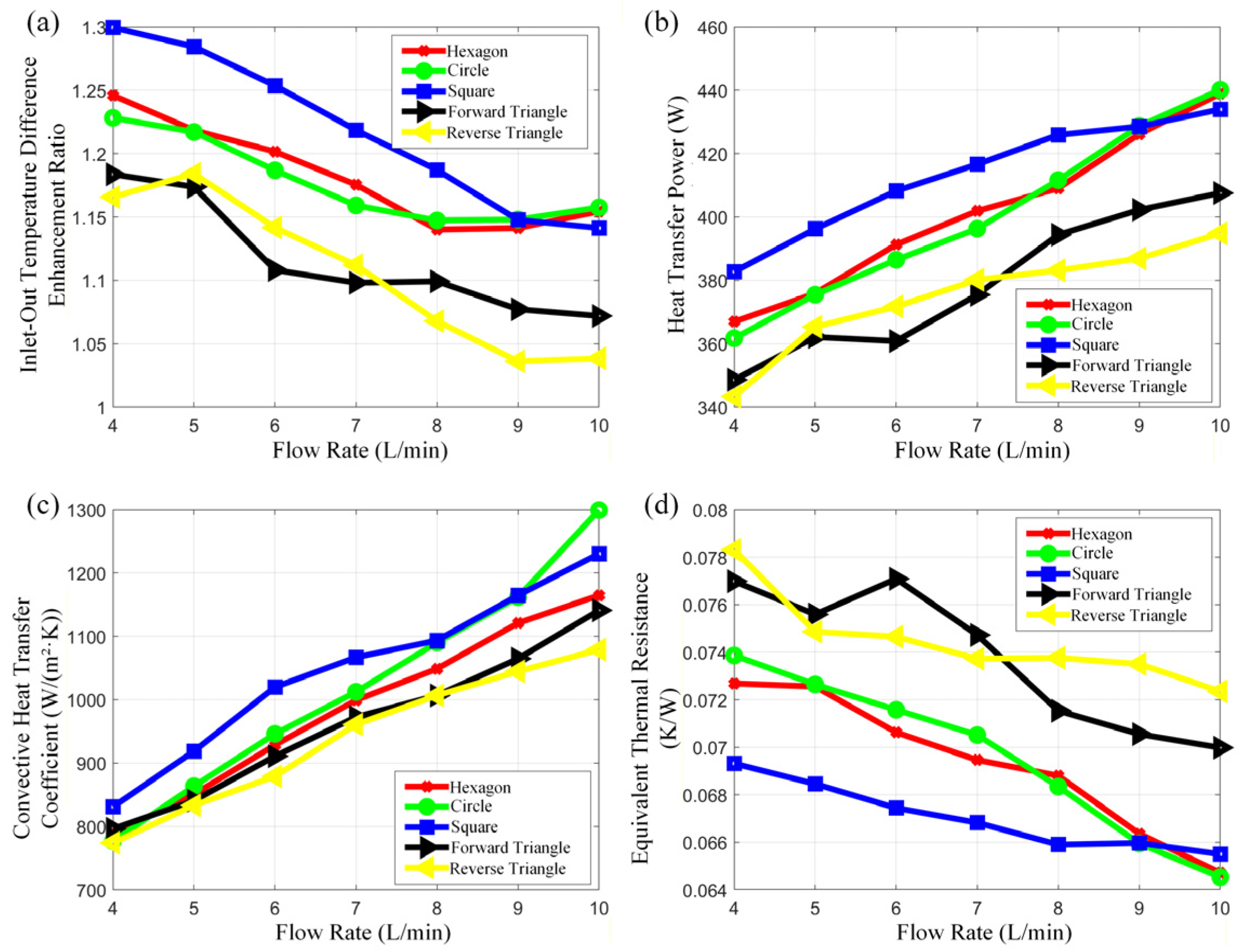
Figure 26 presents the inlet–outlet temperature difference, heat transfer power, average convective heat transfer coefficient, and equivalent thermal resistance of different structural configurations obtained from numerical simulations. As shown in
Figure 26a,b, the composite vortex-inducing–microchannel structures increase both the inlet–outlet temperature difference and the heat transfer power under all operating conditions. The enhancement is more pronounced at low flow rates and gradually weakens as the flow rate increases. Among the investigated configurations, the circular, hexagonal, and square vortex-inducing structures exhibit relatively higher heat transfer power, whereas the reverse-oriented triangular structure yields the lowest performance.
Compared with single vortex-inducing structures, the composite configurations show a slight reduction in heat transfer power under certain operating conditions, which is mainly attributed to flow diversion through microchannels, leading to a reduced main-channel velocity and a corresponding limitation on the convective heat transfer coefficient. As indicated in
Figure 26c, the square and circular structures achieve the highest average convective heat transfer coefficients, while the reverse-oriented triangular structure exhibits the lowest value, suggesting that more uniform temperature fields correspond to stronger convective heat transfer performance.
As illustrated in
Figure 26d, the equivalent thermal resistance of the composite configurations exhibits more pronounced fluctuations with flow rate, reflecting the influence of microchannels on flow uniformity and thermal resistance characterization.
(2) Flow Characteristics Analysis
Figure 27 shows the velocity field contours of several thermal control plate configurations. It can be observed that the flow velocity is relatively high near the inlet and outlet, whereas the main-channel velocity decreases significantly after the coolant is redistributed through the microchannels. The fluid within the microchannels passes through the gaps between vortex-inducing structures and enters the subsequent microchannels, thereby preventing the formation of typical wake regions between adjacent vortex-inducing elements.
Figure 28 presents the pressure field contours of several thermal control plate configurations. It can be observed that the introduction of vortex-inducing structures leads to an overall increase in inlet–outlet pressure drop, indicating an increase in flow resistance. The differences in pressure drop among the various vortex-inducing geometries are relatively small; among them, the reverse-oriented triangular structure exhibits the lowest pressure drop, and its pressure distribution is closest to that of the microchannel thermal control plate without vortex-inducing structures.
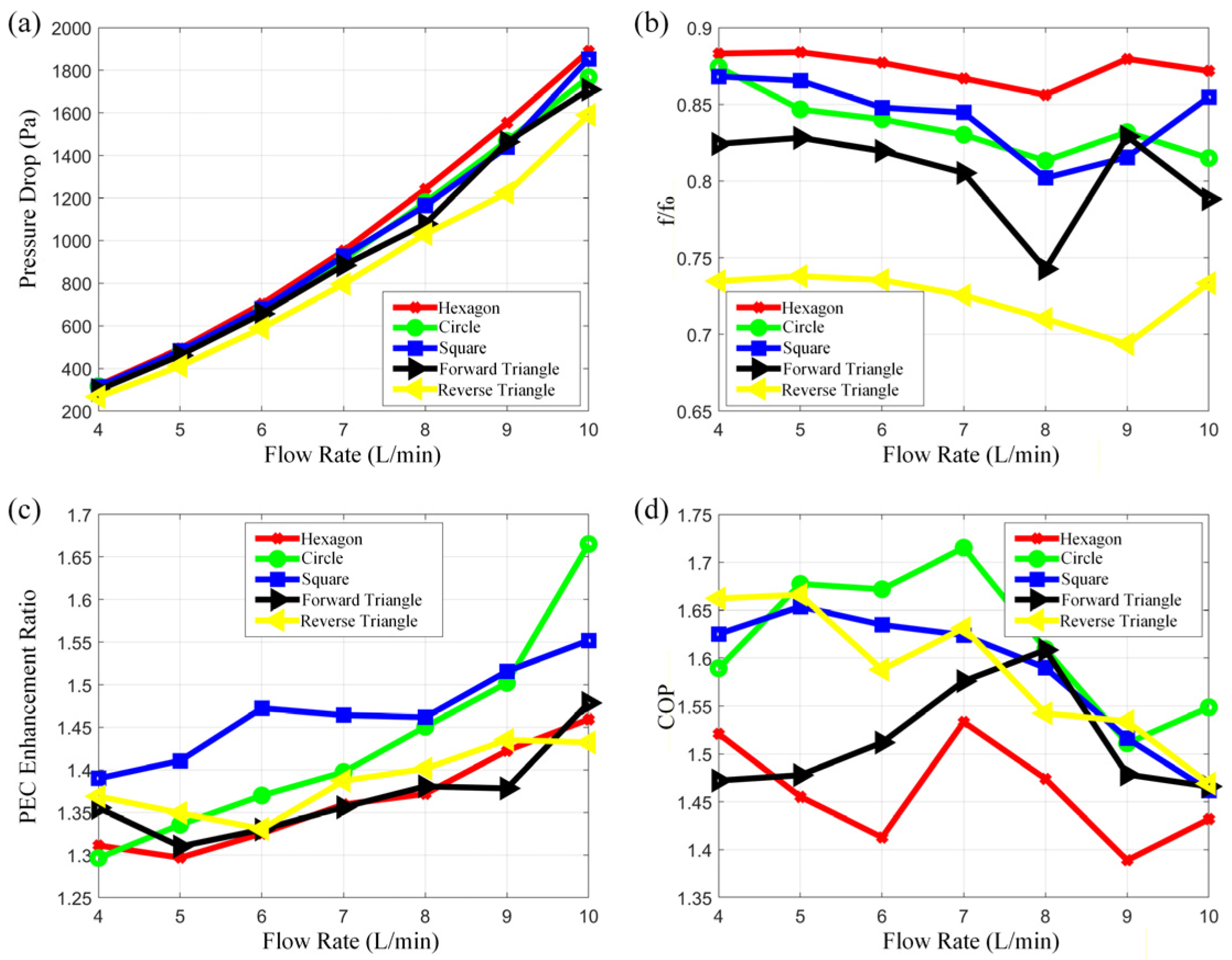
Figure 29 presents the inlet–outlet pressure drop extracted from simulations, as well as the calculated variations in friction factor, PEC, and COP for different structural configurations. As shown in
Figure 29a,b, all vortex-inducing structures lead to an increase in pressure drop and friction factor relative to the microchannel baseline configuration; however, their inlet–outlet pressure drops remain lower than those of the conventional thermal control plate, indicating that the microchannel + vortex-inducing composite configuration effectively suppresses pressure losses. Among the investigated designs, the reverse-oriented triangular structure exhibits the lowest pressure drop, whereas the hexagonal structure produces the highest.
As illustrated in
Figure 29c, the PEC of all composite structures is significantly higher than that of the conventional thermal control plate, and the enhancement becomes more pronounced with increasing flow rate. The circular vortex-inducing structure achieves an approximately 66% PEC improvement at a flow rate of 10 L/min.
As shown in
Figure 29d, the COP of the composite configurations is slightly lower than that of the microchannel thermal control plate but remains superior to that of the conventional thermal control plate, with more substantial improvements under low-flow conditions. Notably, the circular and square vortex-inducing structures achieve COP improvements exceeding 50%, demonstrating a favorable balance between heat transfer enhancement and energy consumption.
Based on the comprehensive simulation results, the vortex-inducing–microchannel composite structure can effectively enhance the heat transfer power of the thermal control plate and reduce the inlet–outlet pressure drop while maintaining a favorable COP. Although the reverse-oriented triangular vortex-inducing structure exhibits a relatively high COP, its capability to improve heat transfer power is limited. In contrast, the circular and square vortex-inducing structures consistently achieve more than a 20% increase in heat transfer power and over a 50% improvement in COP across all operating conditions, making them the most optimal choices for composite enhancement when combined with microchannels.
5. Experimental Validation of the Vortex-Inducing–Microchannel Composite Structure
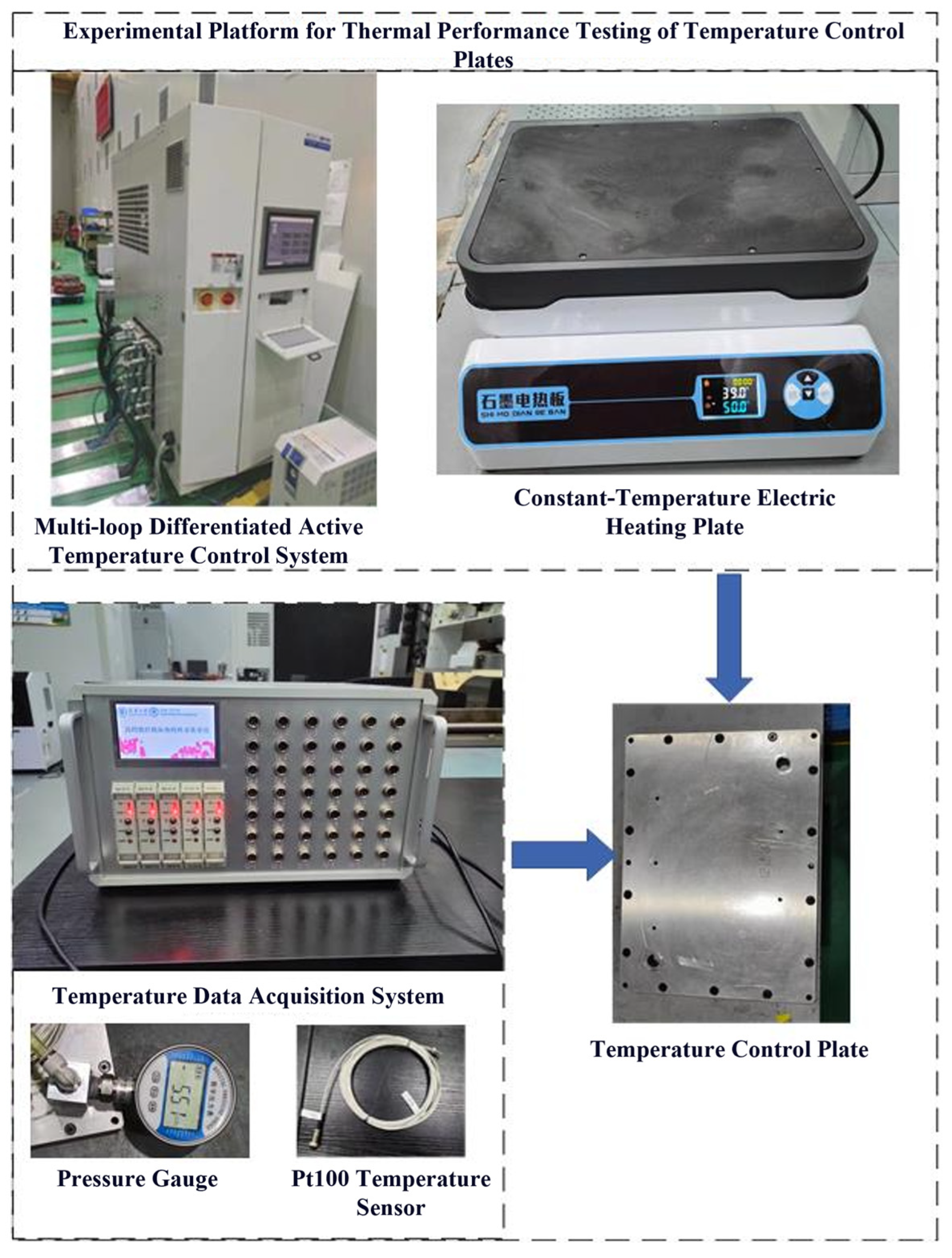
To verify the reliability of the numerical simulations and to validate the equivalent thermal resistance model, a heat transfer and flow performance test platform for the thermal control plate was established, as shown in
Figure 30. The platform consists of a multi-loop differentiated active thermal control system, a temperature acquisition system, and a constant-temperature electric heating plate.
The active thermal control system includes circulation loops, monitoring and data acquisition modules, with a flow rate range of 0–10 L/min and a circulation temperature range of 15–30 °C. A PID controller is employed to regulate the outlet temperature, while a throttle valve is used to adjust the flow rate. The inlet and outlet pressures are measured using 0.4-grade pressure gauges.
The temperature acquisition system comprises a LabVIEW program, an NI data acquisition card, and PT100 temperature sensors. The sensors are arranged at multiple locations along the flow channel as well as at the inlet and outlet. The temperature sensors are inserted into the temperature measurement ports embedded in the thermal control plate to ensure direct contact with the coolant during measurement, with a sampling frequency of 1 s per data point.
The heat source is provided by an HD-SMD4 isostatic high-purity graphite electric heating plate, with a temperature control range from an ambient temperature of +5 °C to 420 °C and a maximum power of 3000 W. Considering the sensor accuracy of ±0.15 °C, the heating plate surface temperature is set to 50 °C to amplify measurable thermal signals.
Two categories of experimental conditions are conducted. The first category focuses on the comparative heat transfer performance of different thermal control plates, with an inlet temperature of 20 °C, a heat source temperature of 50 °C, and an inlet flow rate ranging from 4 to 10 L/min. The second category investigates the effect of heat source temperature, with an inlet temperature of 20 °C, an inlet flow rate of 8 L/min, and a heat source temperature varying from 30 to 50 °C.
Prior to formal testing, an idle test is performed by setting the heat source temperature to 20 °C to eliminate temperature rise caused by friction between the coolant and the thermal control plate. Each test condition is maintained for no less than 10 min to ensure steady-state heat transfer.
After the experiments, the heat transfer power is calculated based on the inlet–outlet temperature difference, while the friction factor is determined from the inlet–outlet pressure drop. Since the average convective heat transfer coefficient is difficult to measure directly, heat transfer performance is characterized using heat transfer power and equivalent thermal resistance, whereas flow performance is evaluated using pressure drop and COP.
Figure 31 presents the experimental comparison of heat transfer performance for different vortex-inducing–microchannel composite thermal control plates. As shown in
Figure 31a,b, the composite structures simultaneously increase the inlet–outlet temperature difference and heat transfer power, with the most pronounced enhancement occurring at low flow rates, while the performance gain gradually diminishes as flow rate increases.
The circular and square vortex-inducing structures exhibit more stable and consistent performance across all operating conditions. Specifically, for the circular structure, the heat transfer power increases from 297.5 W to 363.1 W at 7 L/min, corresponding to an improvement of approximately 37%. For the square structure, the heat transfer power increases from 256.2 W to 306.6 W at 4 L/min, representing an enhancement of approximately 33%. In contrast, the reverse-oriented triangular structure shows the smallest improvement.
To evaluate the reliability of the experimental results, an uncertainty analysis was conducted. The temperature was measured using PT100 sensors with an accuracy of ±0.1 °C, and the data were acquired through an NI data acquisition system with a sampling interval of 1 s. According to the specifications of the flow control system, the uncertainty of the flow rate measurement is within ±1%.
The heat transfer power was calculated based on the measured inlet and outlet temperatures as well as the flow rate. Considering the uncertainties in both temperature difference and flow rate, the uncertainty of the calculated heat transfer power was estimated using the error propagation method. The results indicate that the overall uncertainty of the heat transfer power is within ±4%.
Similarly, the uncertainty of the coefficient of performance (COP), which depends on both the heat transfer power and the pumping power, was also evaluated and found to be within ±5%. These uncertainty levels are acceptable for engineering applications and do not affect the overall trends observed in the experimental results.
As illustrated in
Figure 31c, the introduction of vortex-inducing structures results in an overall reduction in equivalent thermal resistance. Among the tested configurations, the hexagonal, circular, and square structures exhibit lower thermal resistance across all flow rates, indicating superior heat transfer performance. Additionally, the forward-oriented triangular structure yields a lower thermal resistance than the reverse-oriented triangular configuration.
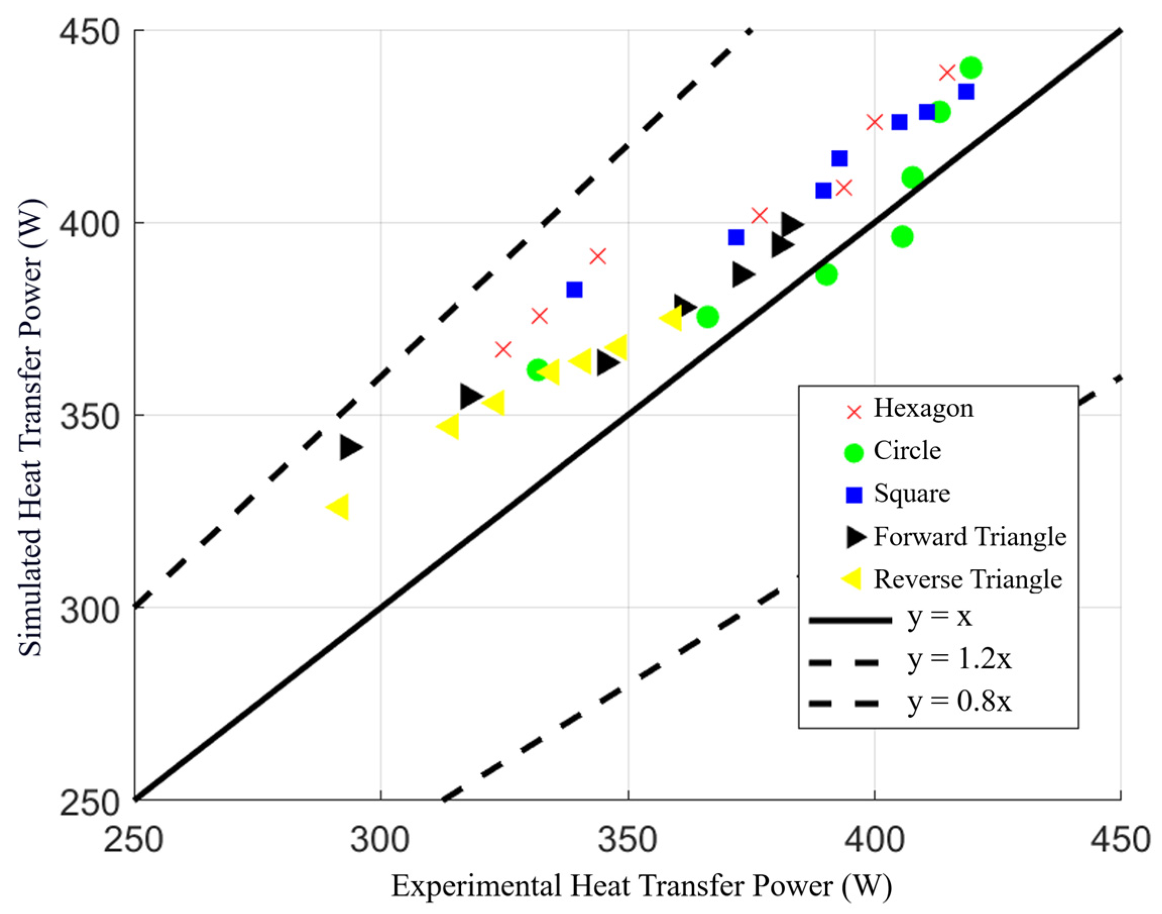
Figure 32 compares the heat transfer power obtained from numerical simulations and experiments. The deviation between simulation and experimental results is controlled within 20%, and most data points are distributed in the upper-left region of the coordinate plane, indicating that the experimentally derived equivalent thermal resistance is generally higher than the simulated value. This discrepancy is primarily attributed to differences in the assumed contact thermal resistance. Meanwhile, the performance trends among different structural configurations remain consistent between simulation and experiment, demonstrating that the numerical model provides a reliable ranking of structural performance.
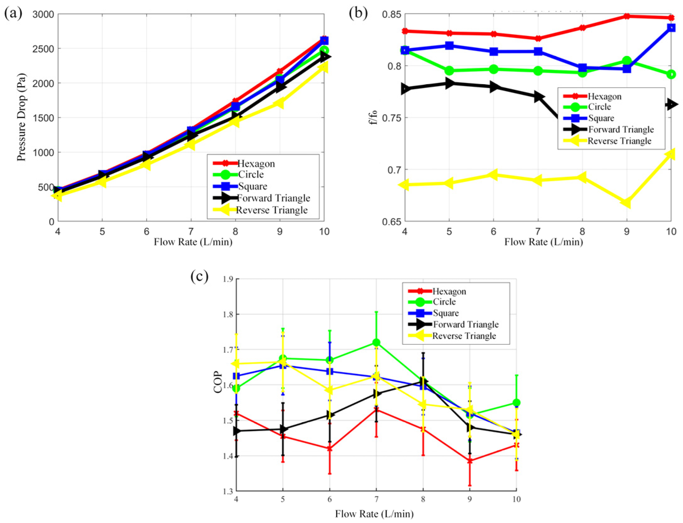
Figure 33 presents the experimental comparison of flow characteristics for microchannel thermal control plates with different vortex-inducing structures. Specifically,
Figure 33a illustrates the inlet–outlet pressure drop of different configurations,
Figure 33b shows the ratio of friction factor relative to that of the conventional thermal control plate, and
Figure 33c depicts the relative improvement in COP compared with the conventional thermal control plate.
As shown in
Figure 33a,b, after introducing vortex-inducing structures into the microchannel thermal control plate, the influence on flow resistance characteristics varies significantly among different vortex geometries. The reverse-oriented triangular vortex-inducing structure exhibits the lowest pressure drop, whereas the hexagonal structure results in the highest pressure drop. Compared with the conventional thermal control plate, all composite configurations demonstrate a reduction in friction factor. Specifically, the hexagonal vortex-inducing structure reduces the friction factor by approximately 15%, while the reverse-oriented triangular structure achieves a reduction of up to 30%, indicating that the microchannel structure partially mitigates the resistance penalty introduced by vortex-inducing elements.
As illustrated in
Figure 33c, the COP of the thermal control plate is significantly enhanced when vortex-inducing structures are combined with microchannels. The vortex-inducing structures improve heat transfer power by strengthening flow disturbance and boundary-layer renewal, while the microchannels suppress energy consumption by reducing pressure losses. The synergistic interaction between these two mechanisms leads to a substantial improvement in COP, demonstrating that the vortex-inducing–microchannel composite structure can effectively enhance the overall performance of the thermal control plate. Among the investigated configurations, the circular and square vortex-inducing structures combined with microchannels exhibit the most outstanding comprehensive performance, achieving more than a 20% increase in heat transfer power while delivering over a 50% improvement in COP. Notably, the circular vortex-inducing–microchannel composite structure attains a maximum COP enhancement of approximately 72% at a flow rate of 7 L/min.
In summary, the integration of vortex-inducing structures and microchannel structures effectively compensates for the limitations of single enhancement strategies in either heat transfer intensification or flow resistance control, enabling a synergistic optimization of heat transfer enhancement and pressure drop reduction. The circular and square vortex-inducing structures demonstrate superior overall performance, consistently achieving more than a 20% improvement in heat transfer power and over a 50% enhancement in COP across the entire tested operating range.