


Abstract
To enhance the navigation efficiency and obstacle avoidance capability of omnidirectional mobile robots in unstructured and complex environments, this paper conducts research on intelligent path planning and management for X-type Mecanum-wheeled mobile robots with the improved Proximal Policy Optimization–Gated Recurrent Unit (PPO-GRU) model on the basis of robot kinematics modeling and deep reinforcement learning. First, by performing kinematic modeling of the X-type Mecanum-wheeled chassis and designing a high-dimensional state space along with a multi-factor composite reward function, the agent training environment for the robot–environment interaction control is established, laying the environmental foundation for in-depth research on path planning. Second, based on the construction of a Proximal Policy Optimization (PPO) path planning model, the PPO model is integrated with Gated Recurrent Units (GRUs) to form an improved PPO-GRU path planning model, thereby achieving an end-to-end path planning strategy. Finally, using a self-developed kinematic simulation platform for the X-type Mecanum-wheeled robot, the rationality and robustness of the proposed path planning model are investigated through ablation experiments, comparative experiments, dynamic environment tests, and tests considering key real-world phenomena. The research results indicate that the improved PPO-GRU path planning model increases the path planning success rate to 96%, reduces the average number of collisions by 82.7%, and achieves an average linear velocity reaching 84.5% of the maximum speed set in the environment. While attaining high-precision and robust planning management for autonomous navigation paths, it significantly improves the response speed of the agent’s autonomous navigation path planning.
1. Introduction
Compared with traditional manual labor, mobile robots [1,2,3] offer strong stability, high work efficiency, easy maintenance, and significantly reduced comprehensive costs for long-term operation. While freeing up human resources, they greatly enhance production safety, thus holding significant application value for industrial applications and logistics transportation. In contrast to the common O-type configuration, the X-type configuration (shown in Figure 1), where the intersection point of the roller axes points toward the geometric center of the mobile robot, enables in situ rotation of the mobile robot. During compound translational motion, the distribution of lateral friction torque of the X-type mobile robot among the wheel sets is more uniform, effectively suppressing yaw drift during omnidirectional movement, demonstrating excellent adaptability to industrial scenarios [4]. Path planning is an essential step in deploying mobile robots to autonomously accomplish task objectives in industrial settings. However, industrial production scenarios are complex and variable. The presence of various uncontrollable environmental factors poses significant challenges for achieving autonomous and efficient path planning for X-type Mecanum-wheeled mobile robots in dynamic environments. Consequently, the efficient and controllable operation of X-type Mecanum-wheeled mobile robots in industrial environments encounters a technical bottleneck due to the lack of highly generalizable path planning models [5,6].
Figure 1.
X-type Mecanum-wheeled mobile robot.
Nguyen et al. [7] studied an optimization framework for mobile robot path planning on the basis of the APF; however, the APF struggles with dynamic obstacles and is prone to deadlocks caused by local minima. Zhang et al. [8] proposed a dual-loop control structure combining LADRC and PID, and used the improved fruit fly optimization algorithm (Le-OFFO) to tune its parameters offline; however, when facing highly unstructured map environments, this method often lacks adaptive capabilities. Pérez-Juárez et al. [9] proposed a kinematic fuzzy controller applicable to Ackermann mobile robots, proving the effectiveness of symmetrical fuzzy rules in reducing system deviations and improving path adaptability. However, this method relies on expert experience-designed fuzzy rules and cannot achieve self-learning with large-scale training. Abut et al. [10] optimized the two-type fuzzy controller using the grey wolf algorithm (GWO). They significantly improved the tracking accuracy in complex paths such as squares and stars compared to the traditional PID control; this solution enhanced the system robustness by using an “uncertainty footprint” (FOU), but the underlying logic still relied on 25 preset expert rules and was unable to achieve end-to-end autonomous evolution of control strategies like PPO-GRU through interaction with the environment. Villalba-Aguilera et al. [11] investigated a three-layer modular architecture for a three-wheeled omnidirectional mobile robot that includes trajectory planning; however, their approach uses traditional Model Predictive Control (MPC) to handle the robot’s kinematic constraints, resulting in significant computational burden, and its real-time response speed in complex and unknown environments is far inferior to that of trained reinforcement learning models. Jia et al. [12] proposed a GRU–Attention-based TD3 Network for robot navigation, utilizing GRUs for temporal feature extraction; however, their work was only validated on a standard two-wheel differential drive robot and not extended to a Mecanum-wheeled platform with a three-dimensional continuous action space. Qin et al. [13] studied a deep reinforcement learning-based strategy for mobile robot path planning in unknown environments, modeling the task as a Partially Observable Markov Decision Process (POMDP); however, their algorithm still used standard PPO (based on fully connected layers), lacking the capability to extract temporal memory from historical observation data. Xu et al. [14] investigated a deep reinforcement learning-based method for trajectory tracking control of omnidirectional mobile robots, where reinforcement learning served only as a kinematic compensation controller and was not integrated with intelligent planning such as obstacle avoidance. Bie et al. [15] employed the PPO algorithm for mobile robot path planning research based on safe path optimization; however, their training was entirely conducted on a simplified 2D grid map and did not transform the discrete mathematical model into a continuous control interaction platform (such as Gym, which contains complex physical parameters). Li et al. [16] utilized prioritized experience replay and LSTM networks for dynamic robot path planning. While they introduced LSTM to address dynamic prediction, their underlying algorithm was a variant of Q-learning with a discrete action space, which cannot satisfy the continuous and smooth control requirements of a Mecanum-wheeled chassis. Zhou [17] investigated path planning for mobile robots in partially observable environments and proposed a dense reward mechanism to guide PPO training; however, their reward function design remained at the level of “distance and collision avoidance”, lacking the physical attitude constraints specific to the wheel-mounted chassis. Trojnacki et al. [18] studied the tracking control methods for four-wheel independently driven robots with slip compensation, providing a detailed analysis of the slip characteristics; however, their approach relied on traditional lookup tables and feedback compensation, lacking the capability for agent self error exploration and policy evolution. Alcayaga et al. [19] demonstrated the importance of memory networks for slip-prone chassis; however, their research focused on underlying trajectory “tracking” for tracked skid-steer robots and lacked the ability to perform global dynamic “obstacle avoidance planning”. Xing et al. [20] studied robot path planning using deep reinforcement learning and a tracing optimization algorithm; however, the model’s 2D continuous action output did not account for the complex kinematic constraints of multi-degree-of-freedom omnidirectional chassis; furthermore, the agent’s core network was composed of simple fully connected layers, lacking a memory module for extracting temporal features, making it difficult to adapt to complex dynamic environments. Magnusson et al. [21] addressed the slow convergence of the Advantage Actor Critic (A2C) algorithm in complex scenarios through incremental training. However, the A2C framework often suffers from unstable policy updates when dealing with high-dimensional continuous action spaces, such as those required by X-type Mecanum-wheeled chassis. Wang et al. [22] integrated the Human Learning Optimization algorithm with the Dynamic Window algorithm for path planning research; however, this algorithm essentially relies on reactive trajectory simulation based on a current environmental snapshot, and due to the lack of a temporal memory module, it struggles to effectively predict and avoid moving obstacles in complex, dynamic scenes. Jiang et al. [23] studied an indoor evacuation optimal path planning model based on computer vision and the Dijkstra algorithm. While this model shows significant advantages in predicting dynamic environmental evolution by incorporating multi-target tracking technology, it primarily targets macroscopic crowd evacuation scheduling and cannot be directly applied to mobile robot path planning. Wu et al. [24] proposed a Voronoi-based fusion path planning method to address issues such as excessive turning points, unsmooth operation, and low safety in mobile robot path planning on grid maps; however, its local obstacle avoidance relies on memoryless, reactive 2D velocity sampling, which neither adapts to the omnidirectional kinematic characteristics of the X-type Mecanum-wheeled chassis nor can it effectively predict and avoid complex dynamic obstacles. Cai et al. [25] proposed a balanced whale algorithm based on harmony secondary optimization to solve the optimal path for ground unmanned vehicle path planning; however, the algorithm lacks a temporal memory mechanism, making it difficult to achieve obstacle avoidance in complex dynamic environments; furthermore, it cannot address the kinematic adaptation problem of omnidirectional chassis, such as the X-type Mecanum-wheel, in a continuous action space. Xiao et al. [26] addressed issues such as poor global search efficiency, slow convergence, excessive turns, and insufficient smoothness of the ant colony algorithm in complex environment path planning by improving the algorithm; however, this discrete heuristic search lacks temporal perception ability, making it difficult for it to handle high-density dynamic-obstacle environments; furthermore, its pure geometric path smoothing processing is detached from the continuous control space and cannot adapt to the complex kinematic constraints of the X-type Mecanum-wheeled chassis. Li et al. [27] proposed an improved ant colony algorithm integrated with a reinforcement learning mechanism to tackle problems like low search efficiency, susceptibility to deadlocks, and local optima in traditional ant colony algorithms for path planning; however, their strategy is confined to discrete state optimization and lacks a temporal awareness mechanism, and its non-continuous action output cannot accommodate the kinematic constraints of the X-type Mecanum-wheeled chassis. Xie et al. [28] proposed an end-to-end autonomous navigation strategy for multiple mobile robots based on Attention–Velocity Obstacle–Soft Actor Critic (Attention-VO-SAC) for mobile robot navigation research; however, the Velocity Obstacle method integrated into this strategy overly relies on idealized geometric collision assumptions; moreover, the network architecture focuses on spatial attention interactions among multiple agents and lacks a dedicated memory network module for extracting dynamic temporal features. From the research summarized above, it is evident that scholars, both domestic and international, have conducted extensive scientific exploration in the field of path planning. This provides theoretical and technical support for the study of intelligent path planning and management for X-type Mecanum-wheeled mobile robots. However, existing research still exhibits significant limitations when addressing path planning for omnidirectional robots in complex dynamic environments: (1) Most existing algorithms rely on discrete action spaces or simplified 2D control (only providing deviation angle and velocity); they cannot be applied to complex omnidirectional kinematic constraints such as those of X-type Mecanum-wheeled chassis. (2) The design of reward functions in reinforcement learning often lacks a composite guidance mechanism that integrates environmental perception and physical constraints like chassis posture, and this hinders the achievement of efficient path planning in dynamic environments. (3) The majority of traditional algorithms and basic reinforcement learning networks fail to utilize historical observation data, lacking a temporal memory mechanism. This makes it difficult to perform trajectory prediction and obstacle avoidance when faced with high-density dynamic obstacles.
In view of the problems existing in the above-mentioned research, this paper will design a high-dimensional state space for a mobile robot that integrates environmental perception, goal guidance, and temporal memory. It will construct a composite reward function that considers multiple influencing factors and build a robot–environment interactive training environment based on Gym. Building upon the established Proximal Policy Optimization (PPO)-based path planning model, to further enhance the success rate and effectiveness of path planning, Gated Recurrent Units (GRUs) will be embedded into the Actor–Critic framework of the PPO path planning model to imbue it with temporal perception. This will yield an improved PPO-GRU path planning model. Subsequently, ablation experiments, comparative experiments, dynamic environment testing experiments, and test experiments considering key real-world phenomena will be designed to validate and analyze the comprehensive performance of the improved PPO-GRU path planning model.
Our contribution in this paper is threefold:
- (1)
- A high-dimensional state space integrating environmental perception, goal guidance, and temporal memory is innovatively designed, and a composite reward function considering multiple influencing factors is also innovatively designed. Based on the kinematic modeling of the X-type Mecanum-wheeled mobile robot, the discrete mathematical model is transformed into a numerical simulation platform for interaction with reinforcement learning algorithms through Gym.
- (2)
- By embedding GRUs into the Actor–Critic framework, the PPO path planning model is innovatively improved, thereby obtaining a PPO-GRU-based path planning model with temporal perception capability.
- (3)
- The effectiveness and reliability of the improved PPO-GRU path planning model are comprehensively validated through ablation experiments, comparative experiments with multiple path planning algorithms, analysis of path planning characteristic evolution and path planning capability over multiple rounds in dynamic environments, and performance analysis of path planning considering key real-world phenomena.
The research route of this paper is as follows. Section 1 summarizes the current progress and shortcomings of mobile robot path planning and points out the research content and innovation of this paper. Section 2 constructs a reinforcement learning environment based on Gym by performing kinematic modeling of the X-type Mecanum-wheeled mobile robot, designing the state space and the composite reward function. Section 3 establishes a PPO path planning model based on the Actor–Critic framework and improves it by updating its dual-network architecture to establish the PPO-GRU path planning model. Section 4 comprehensively investigates the path planning performance of the improved PPO-GRU through ablation experiments based on PPO and PPO-GRU, comparative path planning experiments between PPO-GRU and multiple path planning algorithms, path planning tests of PPO-GRU in environments with high-density moving obstacles, and path planning considering key real-world phenomena. Section 5 presents the research conclusions and related work.
2. Construction of the Agent Training Environment for the Mobile Robot
2.1. Kinematic Modeling of X-Type Mecanum-Wheeled Mobile Robot
The X-type Mecanum-wheeled mobile robot selected in this paper, shown in Figure 1, has dimensions of 766 mm × 632 mm, with Mecanum wheels of 152 mm diameter and alloy hubs. Its maximum speed is 3.8 m/s, and it uses a laser radar for navigation and obstacle avoidance. To achieve precise path planning for the X-type Mecanum-wheeled mobile robot, its chassis kinematic model is established, as shown in the two-dimensional schematic diagram in Figure 2.
Figure 2.
Structure diagram of the X-type Mecanum-wheeled mobile robot.
Firstly, the fuselage coordinate system and world coordinate system are established. Assume that the robot’s pose in the world coordinate system is q. The projection mapping relationship between its corresponding world velocity, , and the body velocity, , is shown in Equation (1):
This projection relationship serves as the foundation for the agent to perceive the global goals and convert them into local control commands. In the PPO-GRU model constructed in the following Section 4.2, the output layer of the neural network is directly mapped to the body velocity command, Vm, enabling end-to-end control of omnidirectional movement.
Based on the kinematic characteristics of the Mecanum wheel, the body velocity command needs to be resolved into the angular velocities of the four driving wheels, . For the X-type configuration, its kinematic model can be described using Equation (2):
where R is the wheel radius and L and W are the longitudinal and lateral distances from the center to the wheel axles, respectively. The matrix J is a 4 × 3 matrix. Through elementary row transformations, it can be determined that the column vectors are always linearly independent under the physical condition (L, W, R) > 0, i.e., rank(J) = 3. Therefore, for any given body velocity command, Vm, there exists a unique wheel speed vector, , corresponding to it. This effectively ensures the determinism of the mapping from the action space of reinforcement learning to the execution space of the physical motors in the subsequent text.
2.2. Design of the State Space for the Mobile Robot
To meet the end-to-end training requirements of the GRU-PPO deep reinforcement learning model discussed later and to ensure the decision-making robustness of the X-type Mecanum-wheeled mobile robot in unstructured environments, the construction of the high-dimensional state space must consider that this state space satisfies the computational power constraints of the industry scene. It must also closely align with the update mechanism of the PPO policy gradient and the temporal extraction characteristics of the GRUs. To obtain a high-dimensional state space, [29], that integrates environmental perception, goal guidance, and temporal memory, the following designs need to be made during its construction:
- (1)
- Polar coordinate representation and rotation invariance of navigation features
Omnidirectional mobile robots undergo frequent pose changes. Using absolute Cartesian coordinates for state-space representation would cause unstable mutations in the robot’s own coordinates during the training process of the path planning algorithm. In contrast, polar coordinate representation possesses rotation invariance, meaning that regardless of the robot’s initial orientation, its perceived navigation logic remains mathematically consistent. Therefore, this paper discards absolute Cartesian coordinates and adopts the relative distance, dgoal, and azimuth angle, ϕgoal, in the robot coordinate system, i.e., polar coordinate representation, for the state-space description of the mobile robot. This effectively reduces the fitting difficulty for the PPO policy network in spatial mapping and accelerates the model’s convergence from any arbitrary starting pose.
- (2)
- Sectorized compression and dimensionality reduction of perceptual information
The GRU network faces the risk of vanishing gradients and increased inference time when processing long sequences of high-dimensional data. Therefore, instead of directly inputting raw point cloud data, this paper adopts a multi-sector minimum distance extraction strategy. This discretizes the high-dimensional LiDAR data into a low-dimensional vector, . By doing so, it retains the core obstacle avoidance constraints while significantly reducing the input dimensionality. This ensures the real-time response of the path planning algorithm within millisecond-level control cycles and meets the demands of the PPO algorithm for high sampling efficiency.
- (3)
- Stability Design of the Robot’s Dynamic State
To enable the agent to perceive its own dynamic limits and avoid generating commands that cause sharp acceleration or deceleration or exceed its motion parameters, the current linear velocities, vx and vy, and the angular velocity, vω, of the robot’s body are explicitly integrated into the state space so as to simulate the feedback of the robot’s own posture and speed from the sensors in reality. Through the smoothness reward design mentioned later and the short-term memory capability of the GRU network, it is ensured that the action output commands of the PPO algorithm conform to the robot’s achievable capabilities and stable operation requirements, thereby ensuring that the robot’s geometric path planning satisfies physical constraints.
- (4)
- Recursive fusion and memory enhancement of the temporal features
Single-frame observations are insufficient for accurately capturing the motion trends of dynamic obstacles. However, the hidden state, ht, utilizing its gate mechanism, can memorize historical observation information to compensate for state deficiencies caused by instantaneous sensor blind spots or noise. Therefore, the aforementioned feature vectors are used as the temporal input for the GRU layer designed in Section 4.2, below. They perform recursive computation in coordination with the hidden state, ht. This endows the PPO decision-making layer with a high-order feature representation of temporal continuity, effectively suppressing the oscillation phenomenon of traditional reinforcement learning in Partially Observable Markov Decision Process (POMDP) environments.
Based on the above considerations, the state vector, st, is defined according to Equation (3):
where dgoal and ϕgoal are the goal features in polar coordinates; represents the environmental perception features; and vx, vy, and vω are the body motion features.
This high-dimensional state space provides a tailored information interface for the PPO-GRU model: it adapts to the computational characteristics of the GRUs through feature dimensionality reduction, constrains the exploration boundaries of PPO through dynamic feedback, and introduces a hidden state to resolve the short-sightedness of single-frame decision-making in dynamic environments. This establishes the necessary mathematical foundation for its stable deployment in the complex environments of industrial sites.
2.3. Design of Composite Reward Function Considering Multiple Influencing Factors
Based on the X-type Mecanum-wheeled omnidirectional kinematic model established in Section 2.1 and the high-dimensional state space constructed in Section 2.2, and to guide the policy search process of the PPO algorithm from geometric path planning towards safe motion control that complies with dynamic constraints, a composite reward function incorporating multiple influencing factors is designed. Considering the decoupling characteristics between the omnidirectional mobile robot’s body orientation and its motion direction, and drawing inspiration from the Artificial Potential Field (APF) method, the following sub-reward items are designed:
- (1)
- Target-guided reward based on potential field gradient () [30,31]
This item constructs a virtual gravitational potential field by calculating the difference in Euclidean distance between the robot and the target point at adjacent moments, as shown in Equation (4):
where represents the gain coefficient of the gravitational field, while and represent the Euclidean distances from the robot’s geometric center to the target point at the previous moment and the current moment, respectively. The purpose of this design is to ensure that the agent can perceive the correct gradient direction at any position on the map, effectively solving the problem of reinforcement learning, where convergence in long-sequence tasks is difficult due to the lack of immediate feedback.
- (2)
- Obstacle Repulsion Reward Based on Potential Field Gradient () [30,31]
This reward term draws on the idea of the APF method and designs a two-layer nonlinear repulsion model. By dividing the perception space into a “caution zone” and a “danger zone”, this model constructs a layered punitive potential field for the agent.
Assume the shortest distance between the robot’s geometric center and the obstacle boundary, denoted as , with the caution threshold denoted as and the danger threshold denoted as . The repulsion penalty, , is constructed as follows:
When < , the target is within the obstacle caution zone. At this point, a flexible penalty, , is imposed to guide the agent to perceive the threat in advance and make path corrections, as shown in Equation (5):
When the robot further encroaches upon the danger threshold, , the target enters the obstacle danger zone. At this point, a rigid penalty, , is applied, forcing the policy network to execute obstacle avoidance actions through a steep gradient change, as shown in Equation (6):
If falls below the physical limit (e.g., 2.0 m), an additional high constant penalty, , is imposed, defining this region as a no-fly zone for policy updates.
To prevent the reward function from experiencing “numerical explosion” in local areas—caused by the directly linear accumulation of repulsive forces from all obstacles—which would make the training process difficult to converge, this paper adopts a maximum-threat value logic, as shown in Equation (7):
where is the set of obstacles within the current LiDAR perception range. This logic ensures that the agent responds only to the single obstacle posing the greatest threat (i.e., the closest one) at each moment, thereby maintaining the numerical stability of the reward signal.
The radar parameters of the X-type Mecanum-wheeled mobile robot selected in this paper, shown in Figure 1, are presented in Table 1.
Table 1.
The radar parameters of the mobile robot.
- (3)
- Dynamic Repulsion and Speed Limit Penalty Based on Velocity Projection () [32]
This reward item balances the contradiction between translational velocity and the system’s obstacle avoidance convergence, preventing collision risks for pedestrians and the instability of the control law caused by excessive lateral movement speed, thereby ensuring dynamic safety in human–robot collaboration environments.
First, transform the velocity, , in the body coordinate system to the world coordinate system. This is done using the kinematic transformation relationship from Section 2.1; the velocity in the world coordinate system can be obtained as shown in Equation (8):
where is the two-dimensional rotation matrix based on the current heading angle, θ, and is the transformed global absolute velocity. Subsequently, the projected component, , of this velocity vector onto the obstacle direction is calculated as shown in Equation (9):
where and are the position vectors of the obstacle and the robot respectively, and represents the velocity component of the robot moving toward the obstacle. Based on this projection, a dynamic velocity threshold, , is set. If exceeds this threshold, an overspeed penalty is applied as shown in Equation (10):
where is the safe speed limit and is the penalty coefficient. This reward function forces the agent to learn to either actively decelerate near obstacles or utilize the characteristics of the Mecanum wheel for lateral evasion, thereby enabling efficient and safe navigation in industrial scenarios involving pedestrians.
- (4)
- Heading Angle Dynamic Alignment Reward () [33]
In practical engineering tasks, robots are often required to maintain specific posture constraints. This paper introduces a heading alignment reward, designed to guide the robot to adjust its heading to the task target angle while approaching the goal, as shown in Equation (11):
where is the weight coefficient for heading alignment and is the relative azimuth angle of the target point in the robot’s coordinate system. This reward is designed to guide the agent to eliminate heading deviation during path planning, ensuring that the robot is in the optimal operational posture upon reaching the target point.
- (5)
- Action Space Smoothness Constraint () [34]
To suppress high-frequency jitter in control commands, the saltation of the penalty speed command of this reward term is shown in Equation (12):
where is the smoothness weight and is the current acceleration vector. This reward term forces the GRU network to the output action sequence with smooth timing, ensuring that the planned trajectory is physically executable.
- (6)
- Sparse Event Feedback () [35]
A significant negative penalty, , is given upon collision, which also terminates the episode; conversely, a positive reward, , is granted upon successful arrival.
By combining these individual reward components, a composite reward function is formulated, defined as shown in Equation (13):
The composite reward function designed in this paper essentially constructs a perception-based dynamic constraint. This enables the X-style Mecanum-wheeled robot not only to avoid obstacles but also to achieve precise control over velocity and posture in narrow spaces, thereby realizing high-precision and safe path planning.
2.4. Construction of an Agent Training Environment Based on Gym
Through the kinematic modeling of the X-style Mecanum-wheeled robot, the design of the state space (defining the perceived state), and the design of the composite reward function described above, the mathematical description of the mobile robot’s motion state and environment design has been achieved. To further transform these discrete mathematical models into a numerical simulation platform that can interact with reinforcement learning algorithms, this section constructs a standardized training environment, OmniWheel-v0, based on the OpenAI Gym framework [36].
As OpenAI’s reinforcement learning toolkit, Gym provides a standardized environment interface for developing and comparing reinforcement learning algorithms [37]. Compared to high-fidelity simulation platforms such as Gazebo and V-REP that rely on rigid-body physics engines, Gym allows the direct integration of the self-constructed kinematic equations from Section 2.1 for state updates. This approach avoids the computational redundancy and numerical instability associated with complex contact dynamics solving, while achieving complete decoupling between the agent and the environment through the standardized interface. The OmniWheel-v0 environment integrates three core subsystems: the physical kinematics solver, the state-space construction module, and the composite reward calculation module. The overall data flow architecture of the environment is shown in Figure 3.
Figure 3.
Reinforcement learning training environment for X-style Mecanum-wheeled robot.
As shown in Figure 3, the environment interacts with the PPO agent through the standard Gym interface. The operational logic of each functional module is as follows:
- (1)
- Physics and kinematics modeling module
The environment receives the action command, , output by the agent; uses the X-style Mecanum wheel kinematic equations to map the body velocity to displacement increments in the world coordinate system; and updates the global coordinates in real time via a pose integrator. The system simultaneously performs collision detection based on the rigid body contour to determine whether the robot has touched an obstacle or successfully reached the target area.
- (2)
- State-space construction module
First, it receives the body pose, velocity, and global coordinates from the physics and kinematics calculation module and uses them to compute the target polar coordinate features and real-time body velocity feedback . A ray-casting algorithm is employed to simulate the physical scanning process of the LiDAR, obtaining compressed sector distance features. After concatenation and normalization of the above data, the reconstructed state vector is ultimately used as the standard observation input for both the policy network and the action network.
- (3)
- Composite reward function module
Based on the multi-factor evaluation system constructed in Section 2.3, it receives state feedback from the physical layer to compute six sub-rewards in parallel, including target attraction (), safety repulsion (), and heading alignment (). The calculated total reward is then transmitted to the agent being trained.
By constructing the Gym-based agent training environment, the comprehensive numerical platform and reliable interactive environment is provided for the subsequent training and validation of path planning algorithms. This platform integrates an omnidirectional kinematics solver, a virtual sensor simulator, and a dynamic evaluation system.
3. Research on Improvements to the Path Planning Model Based on PPO-GRU
3.1. Construction of the Proximal Policy Optimization (PPO) Path Planning Model
Neural networks possess powerful function approximation capabilities and robustness. Their strong anti-interference ability ensures that the mobile robot outputs relatively stable actions even when its state inputs are disturbed by various environmental factors. Consequently, they exhibit superior adaptability and flexibility in path planning applications compared to traditional algorithms. Therefore, this paper selects the Proximal Policy Optimization (PPO) algorithm [38,39,40], which is fundamentally based on a neural network architecture, as the base algorithm for intelligent path planning of the X-type Mecanum-wheeled mobile robot and conducts research on constructing the path planning model. This section will introduce the Actor–Critic dual-network architecture of the PPO algorithm, policy updates based on a clipping mechanism, Generalized Advantage Estimation (GAE), and the overall loss function. On this basis, it will proceed to construct the path planning model based on the Proximal Policy Optimization algorithm.
3.1.1. Design of the Actor–Critic Dual-Network Architecture and System Process
This paper constructs a dual-neural-network system based on the Actor–Critic framework. This system comprises two structurally similar yet functionally independent network modules: the policy network (Actor), which makes decisions based on received state-space vector feedback to directly control the action output of the Mecanum-wheeled robot, and the value network (Critic), which is used to estimate the state value of the current state-space vector.
- (1)
- Policy Network
The policy network, , is responsible for establishing a mapping from perceived states to the action space. As illustrated in Figure 4, the network’s input layer receives the state-space vector, which includes goal-oriented features (), LiDAR perception data (L_scan), and the robot’s body velocity (vx, vy, and vω). The main body of the network consists of three hidden layers, each containing 512 neurons. The output layer generates the variance and mean for each action. These parameters are then used in a Gaussian sampling process to ultimately produce the three-degree-of-freedom velocity commands (Vx, Vy, and Vω) for the X-type Mecanum-wheeled robot.
Figure 4.
Topology diagram of the policy network (Actor).
- (2)
- Value Network
The value network, Vϕ, is designed to fit the value function for the state-space vector, thereby facilitating updates to the policy network. As shown in Figure 5, its network topology maintains consistency with the policy network (three layers, each with 512 dimensions). By employing a similar architecture, the two networks can extract analogous abstract features when processing state inputs. Its output layer produces a scalar value, V(st), representing the expected cumulative reward in the long-term planning given the current state.
Figure 5.
Topology diagram of the value network (Critic).
3.1.2. Policy Updates Based on a Clipping Mechanism
Traditional policy gradient algorithms are prone to difficulties in converging to an optimal path planning model due to excessively large update steps. During the training of the Mecanum-wheeled robot’s path planning model, a few rounds of excellent performance might lead to overly confident parameter updates. This can cause violent oscillations or even divergence in the policy parameters, resulting in a sharp decline in the robot’s navigation performance. The PPO algorithm addresses this challenge by introducing the probability ratio, rt(θ), and its clipping operation.
The probability ratio, rt(θ), which serves as an indicator of the degree of difference between the old and new policies, is defined as shown in Equation (14):
Its core objective function, LCLIP, is constructed as shown in Equation (15):
where represents the estimation of the advantage function and ϵ is the clipping hyperparameter. Through the min and clip operations, the algorithm constrains policy updates within a “trust region” of [1 − ϵ, 1 + ϵ], ensuring that parameters are not updated drastically due to a few instances of excellent performance. This mechanism guarantees that the action distribution does not change drastically during each iteration, thereby ensuring a steady improvement in the Mecanum-wheeled robot’s navigation performance throughout the training process.
3.1.3. Generalized Advantage Estimation and the Overall Loss Function
To balance the bias and variance of gradient estimation—ensuring that the Mecanum-wheeled robot’s navigation avoids the situation where the Mauley robot navigation gets trapped in a local optimal solution while maintaining the training speed of the path planning model—the model incorporates Generalized Advantage Estimation (GAE). GAE calculates the advantage value, , using an exponentially weighted average of Temporal-Difference (TD) errors, as shown in Equation (16):
where represents the environmental reward at the current time step, γ is the discount factor, and λ is the smoothing parameter for GAE.
Additionally, we need to construct the value function loss, LVF(ϕ), to update the parameters of the Critic network. Here, the Mean Squared Error (MSE) is employed to minimize the discrepancy between the predicted value and the target value, as shown in Equation (17):
where the target value, , can be derived from the advantage function as .
Furthermore, to ensure that the Mecanum-wheeled robot conducts sufficient exploration in unknown environments during the early stages of the training, the randomness of the action distribution needs to be maintained. This paper also introduces the information entropy of the output distribution of the policy network, . Its mathematical definition is shown in Equation (18):
The uncertainty of the policy output is quantified by the entropy of the action probability distribution. A smaller entropy value indicates that the current policy is more deterministic (i.e., the model is overly confident). Introducing this entropy term into the total loss function can effectively suppress such premature confidence, thereby encouraging the agent to fully explore the environment during the early stages of training. This helps prevent the path planning model from converging to a local optimum or prematurely halting learning.
Finally, the overall optimization objective, LTotal, for the entire Proximal Policy Optimization (PPO) model is composed of a weighted combination of the policy loss; the value function loss, LVF; and an information entropy reward, S[πθ], as shown in Equation (19):
where c1 and c2 are the weighting coefficients corresponding to the value network loss and the information entropy respectively.
3.1.4. Construction of the Path Planning Model Based on the PPO Algorithm
To achieve end-to-end mapping from high-dimensional perception to continuous actions, a path planning model based on the PPO algorithm is constructed using the aforementioned two basic networks, policy updates based on a clipping mechanism, Generalized Advantage Estimation (GAE), and the overall loss function. Built upon the Actor–Critic architecture, its complete operational workflow is illustrated in Figure 6.
Figure 6.
Path planning model based on the PPO algorithm.
The model consists of two main components: an Interaction Loop and a Network Update Mechanism.
(1) Interaction Loop: The agent applies the action generated by the Actor network to the Mecanum-wheeled robot’s environment. The resulting state transition data (s, a, r, s’, done) is stored in real time in the Replay Buffer.
(2) Network Update:
(1) First, perform the advantage calculation. Utilizing the scalar value, V(s), output by the Critic network, the advantage function, Â, is calculated in combination with GAE to balance bias and variance.
(2) Then, a joint optimization process is carried out. The system updates both networks simultaneously through back propagation:
① The Critic network approximates the target value by minimizing the mean square error.
② The Actor network maximizes the clipped objective function, using the advantage function, Â, to guide the policy to iteratively move towards higher returns. At the same time, it limits the update step size through the clipping mechanism (Clip ϵ) to prevent policy oscillations.
3.2. Research on Improvements to the Path Planning Model Based on PPO-GRU
From a theoretical perspective, the PPO path planning model can achieve relatively good performance in fully observable environments. However, in practical navigation tasks, mobile robots often face challenges such as being unable to infer the velocity of obstacles from single-frame LiDAR data and failing to perceive the inertial effects of changes in their own body velocity. These limitations expose the mobile robot to the challenges of Partially Observable Markov Decision Processes (POMDPs). In environments with movable obstacles, this can even lead to path planning failures, potentially resulting in collisions between the mobile robot and moving obstacles.
To address these issues, Gated Recurrent Units (GRUs) [41,42,43] will be embedded within the Actor–Critic framework to improve the PPO-based path planning model. This enhancement aims to construct a PPO-GRU-based path planning model with temporal awareness, enabling the mobile robot to achieve a deeper understanding of dynamic environments and conduct effective path planning.
3.2.1. Gated Recurrent Unit (GRU) Temporal Feature Extraction Mechanism
As an efficient variant of Recurrent Neural Networks (RNNs), the Gated Recurrent Unit (GRU) effectively addresses the issue of mobile robots being unable to remember previous states during path planning through its gating mechanism. Its internal information processing logic is illustrated in Figure 7.
Figure 7.
The internal state update mechanism of GRUs.
As shown in Figure 7, the GRU regulates the fusion of the current input, st, and the historical hidden state, ht−1, through two core gating controls:
- (1)
- Reset Gate (rt): This determines how much redundant information to discard from the historical memory, ht−1, aiming to capture abrupt changes characteristics in the environment.
- (2)
- Update Gate (zt): This controls the proportion by which the new candidate memory, , updates the final hidden state, ht, ensuring that the model can maintain long-term locking of the target’s bearing.
Through these mechanisms, the GRU transforms the discrete time-step observation sequence into continuous hidden feature vectors, thereby providing temporal memory for subsequent decision-making.
3.2.2. Design of the PPO-GRU Integrated Network Architecture
To enable the policy network and value network to output based on historical information, thereby granting short-term memory capabilities, the underlying Actor–Critic network architecture of PPO is modified by leveraging the temporal characteristics of GRUs. As shown in Figure 8, the improved network introduces a shared GRU layer (Hidden_Dim = 512) that replaces the originally independent fully connected layers.
Figure 8.
Improved Actor–Critic network.
The flow of the data within the network is restructured so that the GRU layer simultaneously receives the current state, st, and the hidden state, ht−1, of the previous moment. It performs recursive computation before feeding data into the policy and value networks, outputting an enhanced vector, ht, that incorporates dynamic trend information. This enhanced vector, ht, is then simultaneously fed into the Actor Head and the Critic Head. The Critic Head evaluates the long-term value, V(st, ht−1), of the current situation based on these temporal features, while the Actor Head outputs the action distribution parameters (μ and σ) to achieve continuous velocity control informed by historical trends.
Embedding the aforementioned network into the PPO algorithm forms a complete system loop for the improved PPO-GRU-based path planning model, as illustrated in Figure 9. The figure shows that, compared to the standard PPO model, this new model introduces an additional feedback loop for the hidden state.
Figure 9.
Improved path planning model based on PPO-GRU.
4. Performance Testing of the PPO-GRU Path Planning Model
4.1. Experimental Environment and Parameter Settings
All algorithm training and simulation tests in this paper were completed on a workstation equipped with high-performance computing components. The experiments utilized NVIDIA CUDA 13.0 acceleration technology to conduct large-scale sample collection through 20 parallel simulation environments. The specific software and hardware configurations are shown in Table 2.
Table 2.
Software and hardware configurations of the experimental platform.
To verify the performance of the PPO algorithm and the PPO-GRU algorithm in omnidirectional path planning, this paper establishes a simulation environment featuring multiple moving obstacles and several target points. The robot is required to continuously reach multiple target points within a limited number of steps while avoiding moving obstacles. The specific map parameters and task constraints are shown in Table 3.
Table 3.
Parameter configuration of the simulation environment.
For the PPO-GRU network constructed in Section 3.1, to ensure the stability of the Mecanum-wheeled robot in three-degree-of-freedom control, a relatively small learning rate and clipping coefficient were adopted. The hyperparameters of the PPO-GRU algorithm are shown in Table 4.
Table 4.
The hyperparameters of the PPO-GRU algorithm.
The specific weight distribution for the composite reward function design in the above Section 2.3 is shown in Table 5, below.
Table 5.
Weight allocation of the reward function.
4.2. Research on Path Planning Performance Based on Ablation Experiments
To verify the contribution of the GRU module in the improved PPO-GRU model proposed in this paper when handling dynamic-obstacle maps, this section designs an ablation experiment. The experiment aims to investigate whether the agent’s performance significantly improves after the introduction of the temporal feature extraction module in environments with dynamic obstacles. This section analyzes the performance gap between the two models from two perspectives: training convergence efficiency and adaptability to dynamic scenes.
To strictly control variables, two sets of comparison models were constructed: the PPO path planning model and the improved PPO-GRU path planning model. Both model sets maintained complete consistency in environmental parameters (map size, target point distance, number of obstacles, and composite reward function weights) and differed only in the feature extraction architecture of the neural network. The PPO path planning model uses only a multi-layer fully connected network (MLP) to process the state vector of the current frame, while the PPO-GRU path planning model retains the complete temporal enhancement architecture, utilizing the GRU to memorize historical hidden states, enabling the agent to infer the dynamic change characteristics of obstacles using historical observations.
4.2.1. Training Convergence Performance and Stability Analysis
Figure 10 illustrates the convergence curves of the average episode reward for the PPO path planning model and the improved PPO-GRU path planning model over 1750 episodes (approximately 2 million time steps). The training map is set such that the robot needs to visit two randomly distributed target points (T1 ⟶ T2) on the two-dimensional map; meanwhile, there are five dynamic obstacles distributed in the environment, with a radius ranging from 1.5 to 2.5 m. They move back and forth at a speed of , aiming to train the agent to adapt to the map environment containing the dynamic obstacles with a certain saturation quantity.
Figure 10.
Comparison of the average reward convergence curve during the training process.
As shown in the figure, the PPO path planning model entered a plateau phase after approximately 1000 training episodes, with the average reward stabilizing at around 1500 points. This relatively high positive score indicates that the standard PPO algorithm has acquired basic navigation capabilities, enabling it to successfully reach targets in obstacle-free or simple static environments. However, the curve exhibits significant high-frequency fluctuations (high variance) and consistently fails to break through the 1600-point ceiling. This suggests that when facing interference from dynamic obstacles, the agent lacking temporal memory displays considerable instability: it occasionally succeeds fortunately in favorable conditions (achieving high scores), but it is prone to collisions or getting trapped in infinite loops during complex dynamic interactions (resulting in low scores). This randomness leads to a lowered average score and increased volatility.
The PPO-GRU path planning model exhibited a faster ascent rate in the early stages of training and quickly converged to a high range of 2500 points after 750 episodes. Compared to the PPO path planning model, the GRU module not only increased the average reward ceiling by approximately 66% but also resulted in an exceptionally smooth curve in the later stages. This demonstrates that with the addition of the temporal memory module, the agent avoids frequent collisions or infinite loops during complex dynamic interactions, acquiring a predictive understanding of the dynamic environment during navigation.
The comparison shows that the training convergence performance and stability of the PPO-GRU path planning model are superior to those of the PPO path planning model.
4.2.2. Robustness Testing in Dynamic Environments
To intuitively reveal the decision-making mechanism of the GRU module in complex environmental interactions and compare the robustness of the two algorithms, a single-target navigation experiment with one moving obstacle was first conducted using the PPO path planning model and the PPO-GRU path planning model. Figure 11 captures the actual trajectories of the PPO path planning model and the improved PPO-GRU path planning model in the same dynamic scenario. This map scene was set up with an obstacle with a radius of 10 m moving at a speed of 2 m/s between the starting point and the target point, thereby hindering navigation.
Figure 11.
Comparison of the typical dynamic-obstacle avoidance path trajectories.
As shown in the region of the figure, the PPO path planning model, lacking memory of the historical motion states of obstacles, can only passively dodge based on current instantaneous observations at each frame. This leads to repeated decision-making oscillations, forming a noticeable zigzag trajectory. Unable to predict the dynamic behavior of obstacles, the PPO path planning model is forced to choose an overly conservative route. It deviates significantly downward from the target, moving all the way to the marginal area of to barely bypass the obstacle cluster. This obstacle avoidance strategy greatly increases both the path length and the mission completion time.
By encoding temporal information through the GRU module, the improved PPO-GRU path planning model successfully extracts the periodic motion characteristics of dynamic obstacles. As shown in the figure, the red trajectory begins adjusting its heading before entering the obstacle zone (at ), generating a smooth arc. Unlike the PPO model, the improved PPO-GRU model does not opt for a long-distance detour. Instead, it plans an inscribed curve that closely follows the motion boundaries of the obstacles (with the lowest point controlled at around .
The visualization experiment demonstrates that the improved PPO-GRU path planning model with the added GRU module possesses the capability to remember and avoid dynamic obstacles. In contrast, the original PPO path planning model, lacking memory, cannot capture the movement characteristics of obstacles. This ability to capture obstacle movement enables the X-type Mecanum-wheeled robot to not only perform path planning based on static obstacles but also to predict and avoid moving obstacles such as pedestrians in real time during motion when deployed in industrial environments, which significantly enhances production safety. Consequently, in a single-target navigation task involving one moving obstacle, the PPO-GRU path planning model exhibits stronger robustness compared to the PPO model.
To further comparatively analyze the robustness of both models in dynamic environments, the experiments were designed to maximize the recreation of real-world uncertainty. Therefore, the following key constraints were established: The robot had to start from the origin and continuously and without interruption visit three randomly distributed target points in the space (T1 → T2 → T3). Simultaneously, the environment contained four dynamic obstacles with radii ranging from 1.5 to 2.5 m. These obstacles moved back and forth at vobs = 1.4 m/s (standard adult walking speed), simulating a high-density testing environment with randomly moving dynamic obstacles. At the same time, to ensure a uniform environment, the same random seeds were set, and the model was run consecutively for 100 episodes. Key metrics were recorded, including the navigation success rate and the average planning time, as summarized in Table 6.
Table 6.
Performance comparison of path planning in dynamic scenarios.
As indicated by the data in the table, the 68% success rate of the PPO path planning model aligns with its reward value of 1500. It is not entirely unusable, but a task failure rate (due to collision or timeout) approaching one-third significantly limits its effectiveness in dynamic-obstacle environments. In contrast, with the introduction of GRUs, the success rate of the PPO-GRU path planning model jumps to 96%, and the number of collisions is substantially reduced. This further validates that, after incorporating the GRU module, the path planning algorithm gains short-term memory capability, enabling highly robust navigation in unstructured dynamic environments.
In summary, the ablation experiments in this section demonstrate that the improved PPO-GRU path planning model surpasses the PPO model in all aspects: training convergence performance, stability, success rate, and robustness in dynamic environments.
4.3. Performance Validation of the PPO-GRU Path Planning Model Based on Comparative Experiments
4.3.1. Path Planning Performance Comparison Based on Classic APF
To further validate the performance of the PPO-GRU path planning model, a typical path planning model, the Artificial Potential Field (APF) [44,45,46,47], is adopted as a benchmark. The “U-shaped Trap Scenario” is constructed (the “U-shaped Trap” is the standard map used to test the escape capability of path planning algorithms [48]). The obstacles are arranged in a semi-enclosed structure in the center of the path. The robot’s starting point is located on the open side of the trap at coordinates (2.0, 10.0), and the target point is located on the opposite side of the trap at coordinates (18.0, 10.0). For the APF algorithm, the attraction coefficient, katt = 1.0 and the repulsion coefficient, krep = 60.0. The improved PPO-GRU path planning model maintains the same reward constraints as in the training environment. The path planning trajectories generated by the two algorithms are shown in Figure 12.
Figure 12.
Path planning trajectories of APF and PPO-GRU in front of the U-shaped obstacle.
From the figure, the gradient-descent-based APF algorithm controls the robot such that it approaches the target in a straight line. When the robot enters the interior of the U-shaped trap (around X = 6.0 m), it falls into a typical local minimum trap and is unable to bypass the obstacle, ultimately resulting in the failure of the task. The improved PPO-GRU path planning model initially also attempts a straight-line approach. However, benefiting from the temporal memory mechanism of the GRU, the agent “perceives” that continuing straight ahead will lead to stagnation in rewards. This prompts the robot to veer towards the upper-left earlier, planning a smooth curve along the outer contour of the obstacle. It eventually merges smoothly back into a straight path towards the target. This effectively proves that the improved PPO-GRU path planning model possesses a higher-dimensional understanding of the global map and exhibits superior navigation performance compared to the traditional APF algorithm.
4.3.2. Path Planning Performance Comparison Based on A* and Dynamic Window Approach
A* [49] and the Dynamic Window Approach (DWA) [50] are, respectively, advanced intelligent unmanned vehicle global path planning and local obstacle avoidance planning algorithms used in modern industrial scenarios. Here, the A* algorithm and DWA are adopted as benchmarks, and the path planning capabilities of the PPO-GRU model are compared and studied from the perspectives of global path planning in unstructured scenarios and stability at different speeds.
The size of the dynamic-obstacle environment map is set to 50 m × 50 m. Five obstacles are set to simulate multiple moving pedestrians in an industrial scene, with diameters ranging from 1.0 to 2.0 m. Each obstacle moves back and forth along a 6 m straight line at a speed of 1.4 m per second. The A* algorithm uses grid-based global search and omnidirectional pure tracking control. The spatial grid resolution is 1.0 m, the expansion radius of static obstacles is 1.5 m, and the switching tracking threshold for waypoints is 2.0 m. The DWA algorithm uses the omnidirectional Dynamic Window method, the prediction time is 2.0 s, the time step is 0.1 s, the sampling gradients for linear/angle velocities are all 7, the maximum linear speed is 3.26 m per second, the local perception distance is 20.0 m (exactly the same as the radar line-of-sight of PPO-GRU), and the weights for target guidance and obstacle avoidance penalties are 1.0 and 4.0 respectively. The improved PPO-GRU path planning model still maintains reward constraints consistent with the training environment.
The path planning trajectories of three different algorithms in the scenario of complex targets moving among multiple obstacles are shown in Figure 13. In the map, the random seed is 1008, and the gray-capsule areas represent the active areas of the moving obstacles.
Figure 13.
The path planning trajectories of three different algorithms.
As shown in the figure, the A* algorithm follows the theoretically optimal geometric shortest path to approach the target, G1. However, due to its inability to perceive and respond to dynamic environments, the robot directly entered the movement area of the high-speed dynamic obstacles and collided with the first obstacle (approximately at x = 4.0 m, y = 15.0 m) (the red-cross mark). The DWA algorithm based on local sampling and deduction is superior to A* and eventually reached all the target points. However, during the journey from G2 to G3 (approximately at y = −10.0 m), the trajectory underwent a very drastic change and a “Z”-shape return. This was because the DWA algorithm was limited by the static field of vision and could only make motion decisions based on the current frame’s perception information. When the moving obstacles entered its planned field of view, the cost of the candidate trajectories increased sharply, forcing DWA to take extreme emergency avoidance actions. The improved PPO-GRU path planning model demonstrated excellent robustness during the continuous traversal of three target points (G1 ⟶ G2 ⟶ G3). During the journey to G1, thanks to the temporal memory mechanism of the GRU network, the agent perceived the velocity vector and movement trend of the obstacles and perfectly avoided the movement range of the dynamic obstacles. In contrast, in the obstacle avoidance stage from G2 to G3, by analyzing the movement trend of the obstacles in the short-term memory, it did not choose to bypass the movement range of the dynamic obstacles but instead chose to pass through during the gap between the movements of the obstacles and precisely returned to the target course.
Further, a high-pressure test was conducted based on DWA. In this test, the map was set to a single target point to simulate local obstacle avoidance; six dynamic obstacles were set, with radii ranging from 1.5 to 2.5 m, and their moving speed gradually increased from 0 to 4 m/s. Figure 14 shows the random high-pressure test map under the condition of random seed 11. The setting of the six obstacles led to their blocking the way to the target point, while the extra obstacles were scattered around to interfere with the robot’s decision-making.
Figure 14.
Map of the random high-pressure test.
The moving speed of the dynamic obstacles was gradually increased at an interval of 0.1 m/s, and 200 rounds of high-pressure tests were conducted in each speed range. The path planning performance of PPO-GRU and DWA under different obstacle moving speeds was obtained. In this plot, the abscissa represents the moving speed of the dynamic obstacles, and the ordinate represents the average clearance success rate in 200 rounds of random map tests for the algorithms.
As shown in the Figure 15, for the low-speed dynamic scenarios ranging from 0.0 to 0.5 m/s, both the improved PPO-GRU model and DWA can maintain an extremely high success rate of 100%. As the movement speed of the obstacles increases, a significant performance differentiation can be observed between the two curves. When the obstacle speed exceeds 0.8 m/s, the success rate of DWA shows a significant stepwise decline, and after 2.0 m/s, it experiences intense fluctuations and continuous attenuation, with the lowest success rate dropping to around 65%. Even in the harsh working condition where the obstacle speed is as high as 4.0 m/s, the success rate of the improved PPO-GRU model still remains steadily within the high-level range of 80% to 90%.
Figure 15.
The success rate of path planning under different obstacle movement speeds.
4.4. Robustness Verification of the PPO-GRU Path Planning Model Based on Dynamic Environment Testing
To further evaluate the effectiveness of the improved PPO-GRU path planning model, experiments simulated a mobile robot performing a continuous patrol task in a 50 m × 50 m industrial scene containing movable obstacles. The study investigated the model’s real-time decision-making and robust performance in long-duration, multi-target missions.
4.4.1. Human-like High-Dynamic Scenario Construction
Similarly, to maximize the recreation of real-world uncertainty, the experiment was set up with the following key constraints: The robot had to start from the origin and continuously and without interruption visit three randomly distributed target points in the space (T1 → T2 → T3). The environment contained four dynamic obstacles with radii ranging from 1.5 to 2.5 m, moving back and forth at vobs = 1.4 m/s (standard adult walking speed).
4.4.2. Spatiotemporal Evolution Analysis of the Dynamic-Obstacle Avoidance Process
The path planning evolution sequence of the agent at six key time steps during a typical task was captured, as shown in Figure 16a–f.
Figure 16.
Spatiotemporal evolution sequence of multi-target dynamic-obstacle avoidance task.
Figure 14 illustrates the navigation process of the agent with the PPO-GRU model during multi-target continuous navigation. Faced with dynamic obstacles, the agent did not resort to inefficient strategies such as abrupt stops or excessive detours. Instead, it leveraged the temporal prediction capability of the GRU module to accurately avoid dynamic obstacles. Notably, even when influenced by multiple moving obstacles simultaneously, the agent managed to both avoid obstacles and maintain high-speed progress towards the target. The entire trajectory was rapid and smooth, without any pauses or backtracking, indicating that the model retains efficient autonomous navigation capability even in environments with dynamic obstacles.
4.4.3. Analysis of Kinematic Response Characteristics
To verify the dynamic stability of the aforementioned decisions, Figure 17 and Figure 18 record the velocity and heading response curves throughout the entire task cycle.
Figure 17.
Velocity response in dynamic environment.
Figure 18.
Heading error in dynamic environment.
As shown in Figure 17, even in a highly interfering environment, the robot’s average linear velocity remains at a high level of 2.57 m/s. The velocity curve shows only a brief, intentional dip around t = 23 s (while simultaneously avoiding multiple dynamic obstacles) and remains in a high-speed cruising state for the rest of the time. This demonstrates that the model has a sufficient grasp of the environmental situation, enabling it to confidently adopt an efficient motion strategy. In other words, the improved PPO-GRU path planning model possesses high-speed cruising capability.
As shown in Figure 18, within a period of 5 to 10 s, the robot experiences a relatively large angular deviation while maintaining high-speed cruising. This indicates that the model enables the agent to perform lateral detours without sacrificing speed. Concurrently, the heading error remains within the range of 0.3~0.8 rad for most of the time, demonstrating that the robot maintains a favorable operational posture throughout most of the path planning process. Therefore, this model endows the robot with excellent kinematic response characteristics.
4.4.4. Robustness Statistical Verification
To verify the robustness of this strategy, navigation tests were conducted in 200 rounds of randomly generated dynamic test environments. The test results are presented in Table 7.
Table 7.
Robustness statistics in dynamic multi-target environments.
The statistical data shows that the improved PPO-GRU model achieves a 96.0% task success rate in human-like dynamic environments. Failure cases are primarily concentrated in extreme dynamic blockade scenarios (e.g., dynamic obstacles simultaneously blocking all feasible paths). The model demonstrates stable performance in the vast majority of tests. The average linear velocity of the robot based on the improved PPO-GRU model reaches a high of 2.75 m/s, which is 84.5% of the maximum speed of 3.26 m/s set in the environment, far exceeding the typical “stop-and-go” pattern of traditional algorithms. This indicates that the algorithm not only solves traditional obstacle avoidance and path planning problems, but also achieves the ability to predict dynamic obstacles while maintaining high speed, demonstrating excellent robustness.
4.5. Research on the Performance of the PPO-GRU Path Planning Model Considering Key Real-World Phenomena
During the actual operation of the robot, key real phenomena such as wheel slippage, surface friction changes, and complex inertial dynamics can affect its performance and path planning effect. Based on these considerations, this paper adds a first-order low-pass filter to the Gym environment to simulate the influence of inertia on the robot. Based on Coulomb’s friction law and the setting of the friction coefficient, the maximum acceleration is defined. Actions exceeding the acceleration limit are truncated to simulate the acceleration process of the robot in reality. Normal distribution sampled noise is added to the speed output to simulate the slippage phenomenon. On this basis, the path planning performance of the PPO-GRU path planning model considering the key real phenomena is studied.
4.5.1. Simulation of Key Real-World Phenomena
Due to the influence of inertia, the acceleration process of the wheeled robot in reality exhibits a typical low-pass filtering characteristic. To simulate this physical property, this study introduces a first-order inertial system to simulate the acceleration motion process of the wheeled robot under the influence of inertia, as shown in Equation (20):
where represents the expected command output by the reinforcement learning strategy network at time t; is the theoretical expected acceleration under the condition of ignoring external resistance; is the current actual physical speed of the chassis; and is the inertia time constant of the system, which includes the linear velocity time constant, , and the angular velocity time constant, . The larger the value of , the heavier the chassis mass or the slower the motor response, and the stronger the inertia of the system.
To obtain the theoretical maximum acceleration of the robot body, according to Coulomb’s friction law, the maximum translational acceleration that the chassis can achieve is limited by the maximum static friction force that the ground can provide. Let the mass of the robot be , the gravitational acceleration be , and the combined friction coefficient between the tires and the ground be . The maximum friction force, . From this, the maximum physical acceleration boundary, , for the chassis’s translational motion can be derived as shown in Equation (21):
In the simulation, we extract the translational component of acceleration, . When the acceleration output of the agent exceeds the current acceleration limit, the underlying physical engine will perform an equal-proportion truncation on it, thereby obtaining the actual acceleration, , under the real physical conditions, as shown in Equation (22):
The slipping phenomenon in reality usually occurs due to sudden acceleration or braking with excessive instantaneous acceleration. When the output acceleration of the intelligent agent exceeds the limit, causing , the acceleration in all directions of the robot body will be lost, thereby triggering uncontrollable lateral deviation (sideslip) and yaw disturbance. Therefore, this paper constructs a dynamic Gaussian noise compensation model based on the slip intensity. Firstly, a dimensionless sliding intensity index, , is defined as shown in Equation (23):
Subsequently, random Gaussian noise, ξ(t), that is positively correlated with S(t) is injected into the actual speed at the next time step, thereby enabling the inclusion of the judgment of the slipping condition and the simulation of the slipping phenomenon, as shown in Equation (24):
The slip disturbance term, , follows a normal distribution with zero mean and a variance that dynamically increases with the slip intensity, as shown in Equations (25) and (26):
In conclusion, by combining the first-order inertial system to simulate the influence of inertia on the robot, limiting the acceleration to simulate the real acceleration process, and adding noise to situations exceeding the limit acceleration to simulate the slipping situation, we ultimately obtained Sim-to-Real environment modeling that takes into account key real-world phenomena.
4.5.2. Research on PPO-GRU Path Planning Considering Key Realistic Phenomena
In order to verify the generalization ability and robustness of the improved PPO-GRU model during the process of transfer to the real physical world (Sim-to-Real), this paper conducted a frequency sweep test within a two-dimensional physical parameter space. The map was set such that the model needed to reach two target points in one attempt. The number of dynamic obstacles was set to five, and the moving speed was 1.4 m/s. As shown in Figure 19, the horizontal axis represents the inertia time constant, , of the chassis (ranging from 0.05 to 0.45 s); the vertical axis represents the friction coefficient, μ, between the tire and the ground (ranging from 0.2 to 0.9). The color intensity of the heatmap reflects the average success rate of the model in 100 consecutive random map navigation tests under the current physical parameters.
Figure 19.
Robustness of the PPO-GRU strategy under different combinations of physical parameters.
When and , a large area of deep green high-success-rate bands is presented, and the algorithm’s pass rate remains stable at 77% to 84%. This indicates that on most conventional road surfaces (such as plastic and cement roads) and in medium–low-load conditions, PPO-GRU can effectively overcome the skidding and delay caused by physical disturbances. However, when μ drops below 0.2 (equivalent to extremely slippery ice surfaces or severely contaminated roads), the success rate drops sharply. This shows that under low-adhesion conditions, the algorithm can no longer provide the same effective obstacle avoidance navigation strategy as before; however, relatively speaking, the model exhibits excellent adaptability to inertial changes. Even if the inertia is increased by nine times ( increases from 0.05 to 0.45), the navigation success rate of the model only shows a slight attenuation (from 84% to 75%).
In the lower right corner of the graph (), at this point the aircraft is operating under extremely harsh physical conditions with extremely high inertia and extremely low road adhesion. The success rate has reached its lowest point globally at 63% instead of completely collapsing. However, PPO-GRU is still attempting to avoid obstacles and complete navigation by suppressing the output of actions.
To illustrate that the model still possesses excellent navigation capabilities under challenging physical conditions, we selected a classic trajectory diagram for explanation. Here, the friction coefficient, ; the inertia time constant, , and the simulation model is used to depict the scenario of navigation by the agent on a slippery surface under a heavy load. The trajectory is shown in Figure 20. The map is set such that the agent needs to sequentially reach three target points, with five obstacles present and a movement speed of 1.0 m/s.
Figure 20.
Obstacle avoidance navigation trajectory of PPO-GRU under extreme physical parameters.
Throughout the navigation process, PPO-GRU exhibited the characteristic of a smooth trajectory, which could minimize the centrifugal force of the chassis and prevent the occurrence of skidding. During the journey to G2, when the agent was faced with a huge obstacle movement range, it chose to deflect in advance, indicating that the agent not only predicted the movement trajectory of the obstacle but also reserved a large safety margin to counteract its own inertia.
The speed output curves during the movement process shown in the above map are depicted in Figure 21, Figure 22 and Figure 23. Among them, the red dotted line represents the original output of the neural network, while the blue solid line represents the actual speed constrained by physical conditions.
Figure 21.
Lateral original speed output and actual speed.
Figure 22.
Vertical original speed output and actual speed.
Figure 23.
Original output of angular velocity and actual speed.
Throughout the entire speed response process, the expected command during the initial stage (the red line) rapidly increases. This characteristic actively counteracts the response lag caused by the high inertia of the chassis. During sudden deceleration and significant lane changes (such as at Vx, approximately 10 s, and Vy, approximately 30 s), due to the extremely low friction force limitation, the actual speed (the blue line) shows a significant lag. At this time, the strategy network exhibits a fine-tuning action similar to anti-lock braking (the oscillation and rebound of the red line) to successfully achieve dynamic compensation for the underlying physical skidding, thereby maintaining vehicle stability. This indicates that the intelligent agent can possess excellent generalization ability even when facing a real physical environment.
5. Conclusions and Prospects
5.1. Conclusions
Aiming at the navigation challenges of X-type Mecanum-wheeled omnidirectional mobile robots in complex environments with dynamic obstacles, this paper conducted improvement research on path planning based on PPO-GRU. By establishing a kinematic model of the X-type Mecanum-wheeled omnidirectional mobile robot, constructing its high-dimensional state space, designing a composite reward function considering multiple influencing factors, and building a reinforcement learning environment based on Gym, a PPO path planning model was established. Building upon this, the PPO path planning model was improved by embedding Gated Recurrent Units (GRUs) within the Actor–Critic framework, resulting in a PPO-GRU-based path planning model with temporal perception. Subsequently, the performance of the established model was investigated through ablation experiments, comparative experiments, path planning tests in multiple rounds of dynamic environments, and path planning experiments considering key real-world phenomena. The following conclusions were drawn:
- (1)
- The kinematic modeling of the X-type Mecanum-wheeled mobile robot was established. A state space was designed in polar coordinates, including goal features, environmental perception features, and body motion features. A dynamics-constrained composite reward function based on perception was designed using the concept of the Artificial Potential Field method. An interactive environment for reinforcement learning was built via Gym, providing a reliable numerical simulation platform for the subsequent training of PPO-GRU.
- (2)
- Based on the constructed PPO path planning model, a PPO-GRU-based path planning model with temporal perception ability was obtained by embedding GRUs into the Actor–Critic framework. Combined with the training environment built earlier using Gym, this ultimately provides a complete PPO-GRU reinforcement learning interactive update architecture enabling the robot’s autonomous path planning in dynamic environments.
- (3)
- Ablation experiments were conducted to compare the performance gap between the PPO path planning model and the improved PPO-GRU path planning model. By comparing their convergence curves and performance across multiple rounds in a high-density test environment, the improved PPO-GRU model demonstrated a 41.2% improvement in navigation success rate and an 82.7% reduction in average collision count compared to the PPO model. It performed better in terms of training convergence, stability, success rate, and robustness in dynamic environments than the PPO path planning model.
- (4)
- Comparative experiments were set up to test the path planning and escape capabilities of PPO-GRU and the APF method under identical physical constraints. By observing their performance in classic test scenarios and conducting batch comparative experiments on a test set with various shapes of non-convex obstacles, the planning success rate of the PPO-GRU model reached 96%. Compared to the 42% of the traditional APF method, this represents a 128.6% relative performance improvement, indicating that the improved PPO-GRU model has stronger generalization performance than the traditional APF method.
- (5)
- A human-like high-dynamic scenario was constructed, and the robustness of PPO-GRU was tested through multiple rounds of tests in a high-density obstacle environment with the same parameters. During navigation in the human-like dynamic scenario, the PPO-GRU model demonstrated the ability to avoid dynamic obstacles through its memory capability. In the high-density obstacle environment tests, the PPO-GRU model achieved a task success rate of 96%, with an average linear velocity of 2.57 m/s, reaching 84.5% of the maximum speed configured in the environment. The improved PPO-GRU model not only efficiently completes cruising tasks but also ensures a high planning success rate.
- (6)
- By adding a first-order low-pass filter, setting the friction coefficient, truncating the output of actions exceeding the acceleration limit, and adding normal distribution sampled noise to the speed output, the influence of key real-world phenomena such as inertia, friction, and skidding was simulated. Under the combined effect of inertia, friction, and skidding, the path planning success rate of the PPO-GRU model still remains above 80%, and even in extreme conditions such as ice surfaces, it can still remain above 63%, indicating that the improved PPO-GRU model can be applied to most road surfaces and different load conditions for obstacle avoidance navigation and can also provide navigation references in extreme road conditions.
This paper provides a GRU-based improved PPO path planning model for mobile robot navigation that combines robustness with real-time responsiveness. It constructs a closed-loop decision-making system from high-dimensional perception to continuous smooth control, offering theoretical guidance and a research foundation for the autonomous navigation of X-type Mecanum-wheeled mobile robots in dynamic environments. It also provides an engineering-practical solution for intelligent mobile robot navigation and control in complex human–robot coexistence environments.
5.2. Research Limitations and Future Prospects
- (1)
- This study only considered the motion obstacle avoidance of the Mecanum-wheeled mobile robot chassis on a two-dimensional plane. To better adapt to the real world, in future research, a 3D point cloud will be integrated to consider the obstacle avoidance effect in a stereoscopic environment.
- (2)
- The focus of this study is to find a more effective path planning model. In future research, the performance of the model proposed in this paper will be compared with more modern reinforcement learning architectures to further optimize and improve the proposed model, thereby achieving iterative upgrades in the research and obtaining more accurate path planning algorithms.
- (3)
- This study did not conduct in-depth research on the deployment issue of the proposed model. Due to the extremely high cost and risks of training reinforcement learning models in reality (initial training is bound to result in collisions), for migration to real machines, the next step is to use the sim2real technology for targeted training to adapt to real environments. Through techniques such as domain randomization (randomly perturbing various parameters in the environment, including speed, sensor readings, target coordinates, etc., to simulate possible disturbances in reality) and other technologies, the intelligent agent model can be made to face such relatively simple models of real environments, and end-to-end learning can be used to reinforce the existing model during real machine deployment.
- (4)
- Real phenomena such as wheel slippage, changes in surface friction, and complex inertial dynamics will all affect path planning. In future research, rigorous, complete, and rich experiments will be conducted to study the path planning algorithms under dynamic conditions such as wheel slippage, changes in surface friction, and complex inertial dynamics.
Author Contributions
Conceptualization, S.K.; methodology, N.A., S.Y. and S.K.; software, S.Y.; validation, N.A. and S.Y.; formal analysis, N.A. and S.Y.; investigation, N.A., S.Y. and S.K.; resources, S.K.; data curation, N.A. and S.Y.; writing—original draft preparation, N.A., S.Y. and S.K.; writing—review and editing, N.A., S.Y. and S.K.; visualization, N.A. and S.Y.; supervision, S.K.; project administration, S.K.; funding acquisition, S.K. All authors have read and agreed to the published version of the manuscript.
Funding
This work was supported by the National Natural Science Foundation of China (Grant No. 62573007).
Data Availability Statement
The datasets generated during and/or analyzed during the current study are available from the corresponding author on reasonable request.
Conflicts of Interest
The authors declare no conflicts of interest.
References
- Liu, Y.S.; Xu, Z.X.; He, N.; He, Y.L. Reinforcement learning-driven parameter tuning for mobile robot’s predictive control. J. Harbin Inst. Technol. 2026, 1–12. Available online: https://link.cnki.net/urlid/23.1235.T.20260129.1121.007 (accessed on 17 February 2026).
- Wang, Y.; Ye, Y.Y.; Zhong, W.; Gao, B.L.; Mu, C.Z.; Zhao, N. Micro-Platform Verification for LiDAR SLAM-Based Navigation of Mecanum-Wheeled Robot in Warehouse Environment. World Electr. Veh. J. 2025, 16, 571. [Google Scholar] [CrossRef] [Scilit]
- Lin, S.; Dai, J.; Song, Y.F.; Wang, H.G.; Yuan, B.B. Analysis of Curved Surface Motion Characteristics of Wheeled Mobile Robots with Reconfigurable Trunks. J. Mech. Eng. 2026, 1–14. Available online: https://link.cnki.net/urlid/11.2187.TH.20260106.1654.006 (accessed on 17 February 2026).
- He, C.; Wu, D.; Chen, K.; Liu, F.; Fan, N. Analysis of the Mecanum wheel arrangement of an omnidirectional vehicle. Part C J. Mech. Eng. Sci. 2019, 233, 12. [Google Scholar] [CrossRef] [Scilit]
- Dou, L.; Gao, Y.; He, Z.H.; Lv, A.; Ding, F.P. Simultaneous Localization and Mapping (SLAM) and Path Planning Algorithms Based on RadarVisual Sensor Fusion in Unknown Environments. Comput. Eng. Appl. 2026, 1–14. Available online: https://link.cnki.net/urlid/11.2127.tp.20260130.1042.004 (accessed on 17 February 2026).
- Setiadilaga, O.; Cahyadi, A.; Ataka, A. Mecanum-Wheeled Robot Control Based on Deep Reinforcement Learning. In 2023 15th International Conference on Information Technology and Electrical Engineering (ICITEE), Chiang Mai, Thailand, 2023; IEEE: New York, NY, USA, 2003; pp. 25–30. [Google Scholar] [CrossRef] [Scilit]
- Nguyen, C.T.; Pham, H.-A. Geometric Optimization Frameworks in Mobile Robot Path Planning. IEEE Access 2025, 13, 147127–147162. [Google Scholar] [CrossRef] [Scilit]
- Zhang, X.; Wu, W.; Li, X. A modified fruit fly optimization algorithm to active disturbance rejection control parameters tuning for trajectory tracking of omnidirectional mobile robotic chassis. Soft Comput. 2025, 29, 4401–4421. [Google Scholar] [CrossRef] [Scilit]
- Pérez-Juárez, J.G.; García-Martínez, J.R.; Santiago, A.M.; Cruz-Miguel, E.E.; Olmedo-García, L.F.; Barra-Vázquez, O.A.; Rojas-Hernández, M.A. Kinematic Fuzzy Logic-Based Controller for Trajectory Tracking of Wheeled Mobile Robots in Virtual Environments. Symmetry 2025, 17, 301. [Google Scholar] [CrossRef] [Scilit]
- Abut, T.; Salkim, E. Trajectory Tracking of a Mobile Robot with GWO-Based Type II Fuzzy Logic Controller. Bitlis Eren Üniversitesi Fen Balmier Derg. 2025, 14, 1523–1551. [Google Scholar] [CrossRef] [Scilit]
- Villalba-Aguilera, E.; Blesa, J.; Ponsa, P. Model-Based Predictive Control for Position and Orientation Tracking in a Multilayer Architecture for a Three-Wheeled Omnidirectional Mobile Robot. Robotics 2025, 14, 72. [Google Scholar] [CrossRef] [Scilit]
- Jia, J.; Xing, X.; Chang, D.E. GRU-Attention based TD3 Network for Mobile Robot Navigation. In 2022 22nd International Conference on Control, Automation and Systems (ICCAS), Jeju, Republic of Korea, 2022; IEEE: New York, NY, USA, 2022; pp. 1642–1647. [Google Scholar] [CrossRef] [Scilit]
- Qin, H.; Qiao, B.; Wu, W.; Deng, Y. A Path Planning Algorithm Based on Deep Reinforcement Learning for Mobile Robots in Unknown Environment. In 2022 IEEE 5th Advanced Information Management, Communicates, Electronic and Automation Control Conference (IMCEC), Chongqing, China, 2022; IEEE: New York, NY, USA, 2022; pp. 1661–1666. [Google Scholar] [CrossRef] [Scilit]
- Xu, H.; Terakawa, T.; Komori, M. Deep-reinforcement-learning-based trajectory tracking control for slidable-wheel omnidirectional mobile robot. Bull. JSME J. Adv. Mech. Des. Syst. Manuf. 2025, 19, JAMDSM0031. [Google Scholar] [CrossRef] [Scilit]
- Bie, T.; Zhu, X.; Li, X.; Ruan, X. A Mobile Robot Path Planning Method Based on Safe Pathfinding Guidance. In 2021 33rd Chinese Control and Decision Conference (CCDC), Kunming, China, 2021; IEEE: New York, NY, USA, 2021; pp. 3297–3303. [Google Scholar] [CrossRef] [Scilit]
- Li, H.; Zhong, P.; Liu, L.; Wang, X.; Liu, M.; Yuan, J. Robot Dynamic Path Planning Based on Prioritized Experience Replay and LSTM Network. IEEE Access 2025, 13, 22283–22299. [Google Scholar] [CrossRef] [Scilit]
- Zhou, S. PPO-Based Mobile Robot Path Planning with Dense Bootstrap Reward in Partially Observable Environments. In 2024 21st International Computer Conference on Wavelet Active Media Technology and Information Processing (ICCWAMTIP), Chengdu, China, 2024; IEEE: New York, NY, USA, 2024; pp. 1–6. [Google Scholar] [CrossRef] [Scilit]
- Trojnacki, M. Tracking Control of a Four-Wheeled Skid-Steered Robot with Slip Compensation and Application of the Drive Unit Model. Electronics 2025, 14, 444. [Google Scholar] [CrossRef] [Scilit]
- Alcayaga, J.M.; Menéndez, O.A.; Torres-Torriti, M.A.; Vásconez, J.P.; Arévalo-Ramirez, T.; Romo, A.J.P. LSTM-Enhanced Deep Reinforcement Learning for Robust Trajectory Tracking Control of Skid-Steer Mobile Robots Under Terra-Mechanical Constraints. Robotics 2025, 14, 74. [Google Scholar] [CrossRef] [Scilit]
- Xing, X.; Ding, H.; Liang, Z.; Li, B.; Yang, Z. Robot path planner based on deep reinforcement learning and the seeker optimization algorithm. Mechatronics 2022, 88, 102918. [Google Scholar] [CrossRef] [Scilit]
- Magnusson, M.; Lilienthal, A.; Duckett, T. Scan registration for autonomous mining vehicles using 3D-NDT. J. Field Robot. 2007, 24, 803–827. [Google Scholar] [CrossRef] [Scilit]
- Wang, Q.; Wei, L.S. AGV dynamic obstacle avoidance path planning algorithm based on improved HLO and dynamic window. J. Electron. Meas. Instrum. 2025, 39, 213–221. [Google Scholar] [CrossRef]
- Jiang, H.; Fang, W.; Xu, T.F.; Chen, F.; Zhou, L.; Deng, Q. Optimal indoor evacuation path-planning model based on Dijkstra’s algorithm. J. Tsinghua Univ. (Nat. Sci. Ed.) 2025, 65, 742–749. [Google Scholar] [CrossRef]
- Wu, X.; Li, Y.; Zang, T.G.; Meng, Z.X.; Chen, J.Z.; Wang, C.T.; Xing, L.Y.W. Combined Path Planning Based on Voronoi Skeleton for Mobile Robots. J. Mech. Eng. 2025, 61, 165–177. [Google Scholar] [CrossRef] [Scilit]
- Cai, Y.; Du, P. Path planning of unmanned ground vehicle based on balanced whale optimization algorithm. Control. Decis. 2021, 36, 2647–2655. [Google Scholar] [CrossRef]
- Xiao, J.Z.; Yu, X.; Zhou, G.; Sun, K.; Zhou, Z. An improved ant colony algorithm for indoor AGV path planning. Chin. J. Sci. Instrum. 2022, 43, 277–285. [Google Scholar] [CrossRef]
- Li, Y.; Liao, Z.H.; Li, M.H. An Improved Ant Colony Optimization Algorithm Based on Reinforcement Learning for Mobile Robot Path Planning. Comput. Eng. Appl. 2026. Available online: https://link.cnki.net/urlid/11.2127.TP.20251205.1505.008 (accessed on 17 February 2026).
- Xie, M.; Yu, W.; Chen, M. End-to-end Autonomous Navigation Approach for Multiple mobile Robots Integrating Attention Mechanism and Velocity Obstacle Method. Robot 2026. [Google Scholar] [CrossRef]
- de Heuvel, J.; Zeng, X.; Shi, W.; Sethuraman, T.; Bennewitz, M. Spatiotemporal Attention Enhances Lidar-Based Robot Navigation in Dynamic Environments. arXiv 2023, arXiv:2310.19670. [Google Scholar] [CrossRef] [Scilit]
- Jiang, H.; Li, S.; Zhang, J.; Zhu, Y.; Xu, X.; Liu, D. Efficient state representation with artificial potential fields for reinforcement learning. Complex Intell. Syst. 2023, 9, 4911–4922. [Google Scholar] [CrossRef] [Scilit]
- Li, P.; Wang, Y.; Gao, Z. Path Planning of Mobile Robot Based on Improved TD3 Algorithm. In 2022 IEEE International Conference on Mechatronics and Automation (ICMA), Guilin, China, 2022; IEEE: New York, NY, USA, 2022; pp. 715–720. [Google Scholar] [CrossRef] [Scilit]
- Tao, Y.; Li, M.; Cao, X.; Lu, P. Mobile Robot Collision Avoidance Based on Deep Reinforcement Learning With Motion Constraints. IEEE Trans. Intell. Veh. 2025, 10, 2163–2173. [Google Scholar] [CrossRef] [Scilit]
- Yang, X.; Wang, Q.; Li, J.; Jiang, X. NM-TD3: A Hybrid Noise-Driven TD3 Algorithm With Long-Term Reward Propagation for Mobile Robot Path Planning. IEEE Access 2025, 13, 149921–149932. [Google Scholar] [CrossRef] [Scilit]
- Han, C.; Park, S.; Woo, J. Robust Collision Avoidance for ASVs Using Deep Reinforcement Learning with Sim2Real Methods in Static Obstacle Environments. J. Mar. Sci. Eng. 2025, 13, 1727. [Google Scholar] [CrossRef] [Scilit]
- Park, M.; Park, C.; Kwon, N.K. Autonomous Driving of Mobile Robots in Dynamic Environments Based on Deep Deterministic Policy Gradient: Reward Shaping and Hindsight Experience Replay. Biomimetics 2024, 9, 51. [Google Scholar] [CrossRef] [Scilit]
- Ren, J.; Zeng, Y.; Zhou, S.; Zhang, Y. An Experimental Study on State Representation Extraction for Vision-Based Deep Reinforcement Learning. Appl. Sci. 2021, 11, 10337. [Google Scholar] [CrossRef] [Scilit]
- Rojas, M.; Hermosilla, G.; Yunge, D.; Farias, G. An Easy to Use Deep Reinforcement Learning Library for AI Mobile Robots in Isaac Sim. Appl. Sci. 2022, 12, 8429. [Google Scholar] [CrossRef] [Scilit]
- Guo, B.; Wang, G.; Chen, Y.; Gao, Y.; Xie, Q. Risk-Aware Reinforcement Learning with Dynamic Safety Filter for Collision Risk Mitigation in Mobile Robot Navigation. Sensors 2025, 25, 5488. [Google Scholar] [CrossRef] [Scilit]
- Cheng, W.-C.; Ni, Z.; Zhong, X.; Wei, M. Autonomous Robot Goal Seeking and Collision Avoidance in the Physical World: An Automated Learning and Evaluation Framework Based on the PPO Method. Appl. Sci. 2024, 14, 11020. [Google Scholar] [CrossRef] [Scilit]
- Zhang, Q.; Ma, W.; Zheng, Q.; Zhai, X.; Zhang, W.; Zhang, T.; Wang, S. Path Planning of Mobile Robot in Dynamic Obstacle Avoidance Environment Based on Deep Reinforcement Learning. IEEE Access 2024, 12, 189136–189152. [Google Scholar] [CrossRef] [Scilit]
- Cho, K.; van Merriënboer, B.; Gulcehre, C.; Bahdanau, D.; Bougares, F.; Schwenk, H.; Bengio, Y. Learning Phrase Representations using RNN Encoder-Decoder for Statistical Machine Translation. In Proceedings of the 2014 Conference on Empirical Methods in Natural Language Processing (EMNLP), Doha, Qatar, 25–29 October 2014. [Google Scholar] [CrossRef] [Scilit]
- Jiang, W.; Liu, J.; Wang, W. Global Path Planning for Land-Air Amphibious Biomimetic Robot Based on Improved PPO. Biomimetics 2026, 11, 25. [Google Scholar] [CrossRef] [Scilit] [PubMed]
- Nan, Z.; Nam, H. Multimodal Feature Fusion for Deep Reinforcement Learning-Based Mobile Robot Navigation. In 2025 International Conference on Artificial Intelligence in Information and Communication (ICAIIC), Fukuoka, Japan, 2025; IEEE: New York, NY, USA, 2025; pp. 0893–0897. [Google Scholar] [CrossRef] [Scilit]
- Azizi, M.R.; Rastegarpanah, A.; Stolkin, R. Motion Planning and Control of an Omnidirectional Mobile Robot in Dynamic Environments. Robotics 2021, 10, 48. [Google Scholar] [CrossRef] [Scilit]
- Sun, Z.; Hu, S.; Miao, X.; Chen, B.; Zheng, J.; Man, Z.; Wang, T. Obstacle-avoidance trajectory planning and sliding mode-based tracking control of an omnidirectional mobile robot. Front. Control. Eng. 2023, 4, 1135258. [Google Scholar] [CrossRef] [Scilit]
- Wu, D.; Wei, L.; Wang, G.; Tian, L.; Dai, G. APF-IRRT*: An Improved Informed Rapidly-Exploring Random Trees-Star Algorithm by Introducing Artificial Potential Field Method for Mobile Robot Path Planning. Appl. Sci. 2022, 12, 10905. [Google Scholar] [CrossRef] [Scilit]
- Sun, Z.; Zhang, T.; Zhu, H.; Ma, T.; Bao, X.; Zhang, X. Path Planning for Mobile Robot Based on the Fusion Algorithm of Improved A* and APF. In 2024 6th International Symposium on Robotics & Intelligent Manufacturing Technology (ISRIMT), Changzhou, China, 2024; IEEE: New York, NY, USA, 2024; pp. 113–118. [Google Scholar] [CrossRef] [Scilit]
- Wang, X.; Li, G.; Bian, Z. Research on APF-Dijkstra Path Planning Fusion Algorithm Based on Steering Model and Volume Constraints. Algorithms 2025, 18, 403. [Google Scholar] [CrossRef] [Scilit]
- Kobayashi, M.; Zushii, H.; Nakamura, T.; Motoi, N. Local Path Planning: Dynamic Window Approach With Q-Learning Considering Congestion Environments for Mobile Robot. IEEE Access 2023, 11, 96733–96742. [Google Scholar] [CrossRef] [Scilit]
- Votion, J.; Cao, Y. Diversity-Based Cooperative Multivehicle Path Planning for Risk Management in Costmap Environments. IEEE Trans. Ind. Electron. 2019, 66, 6117–61274. [Google Scholar] [CrossRef] [Scilit]
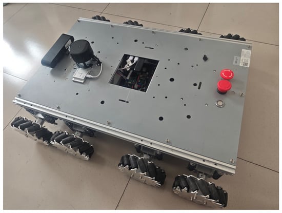
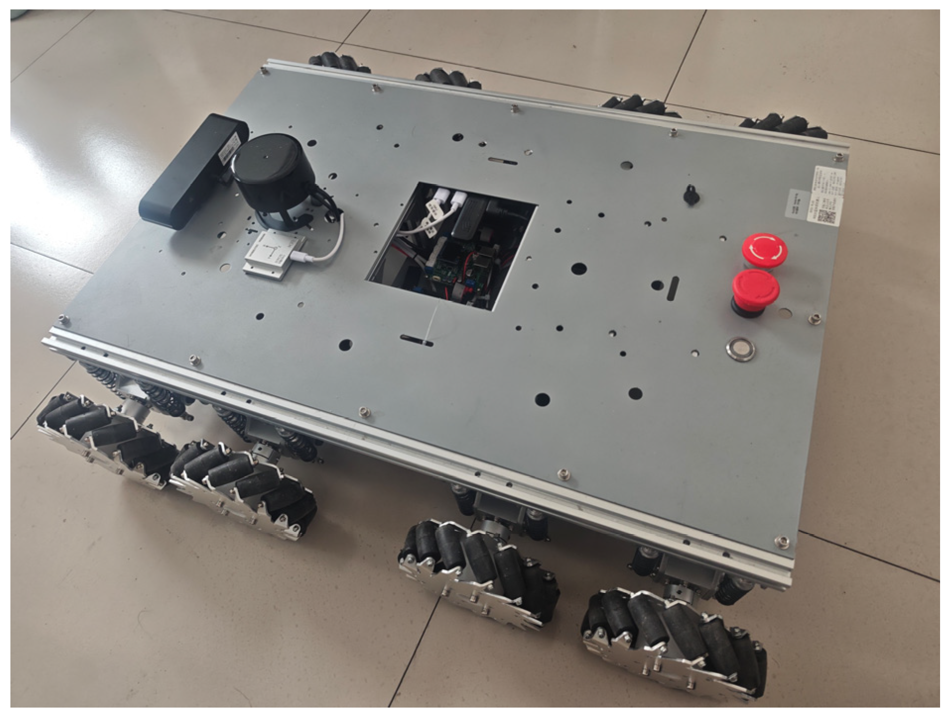
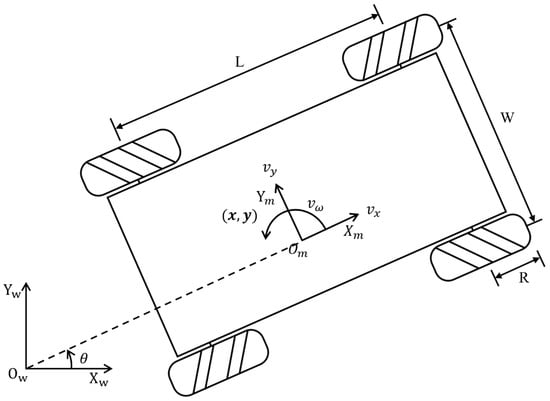
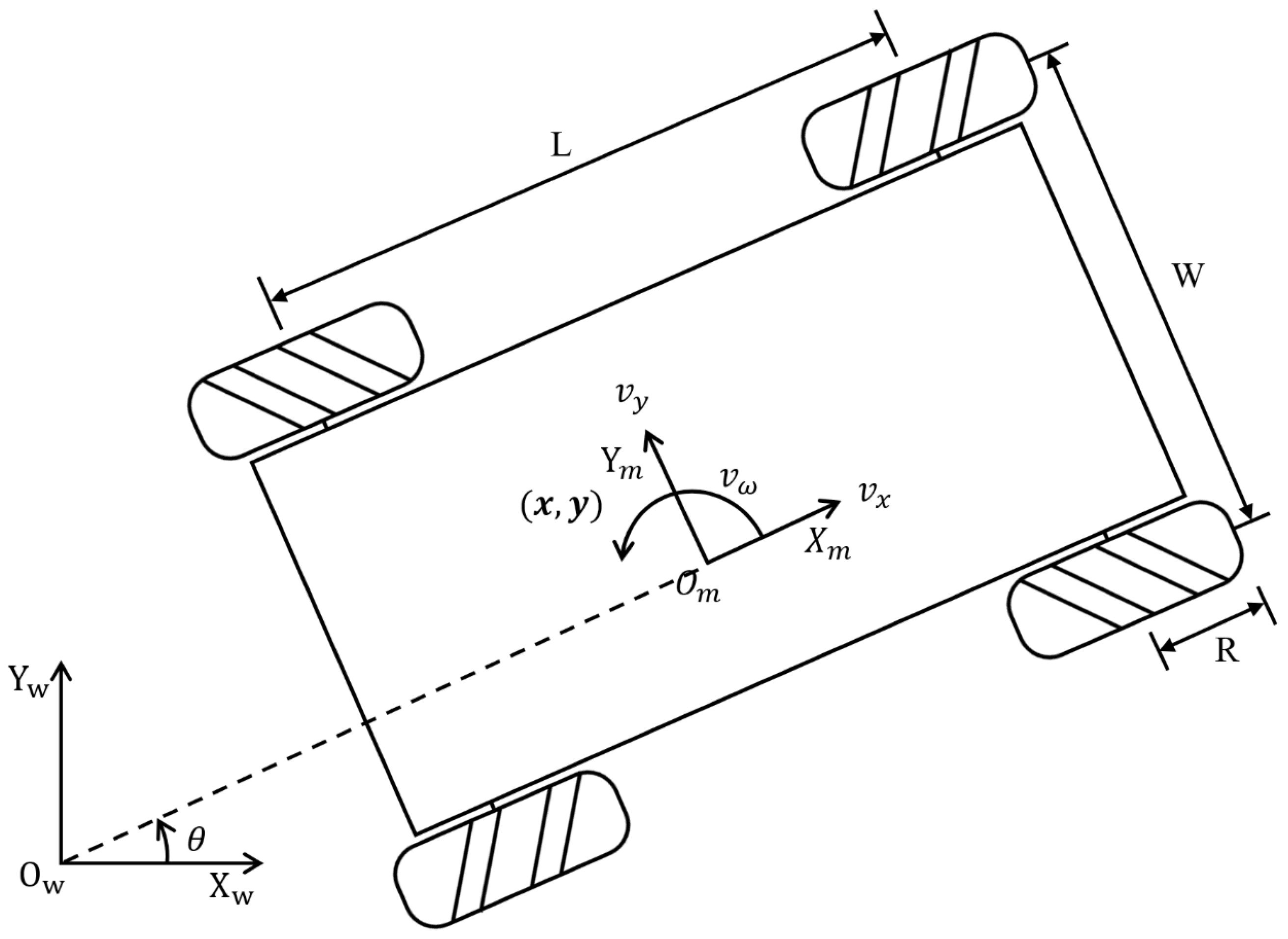
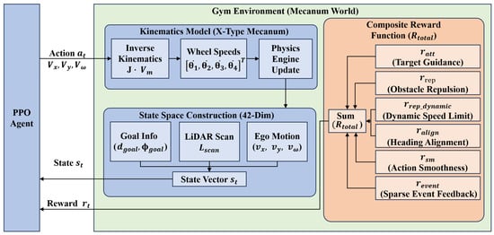
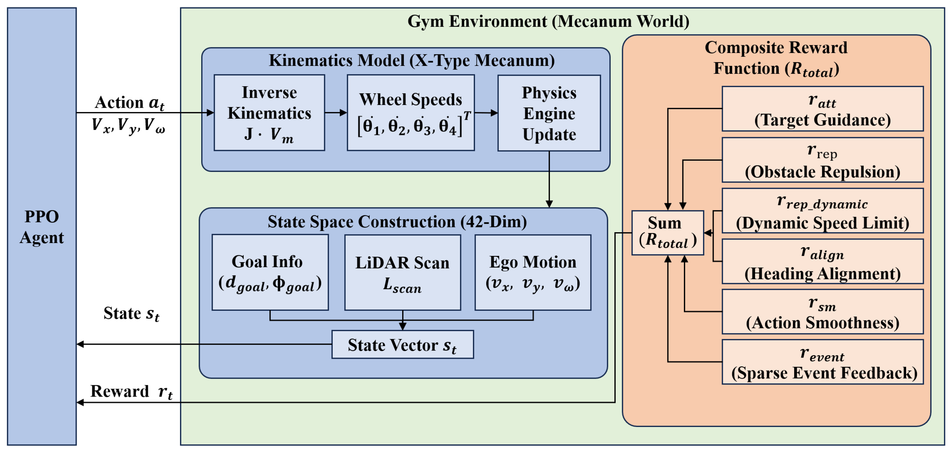
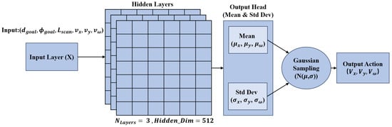
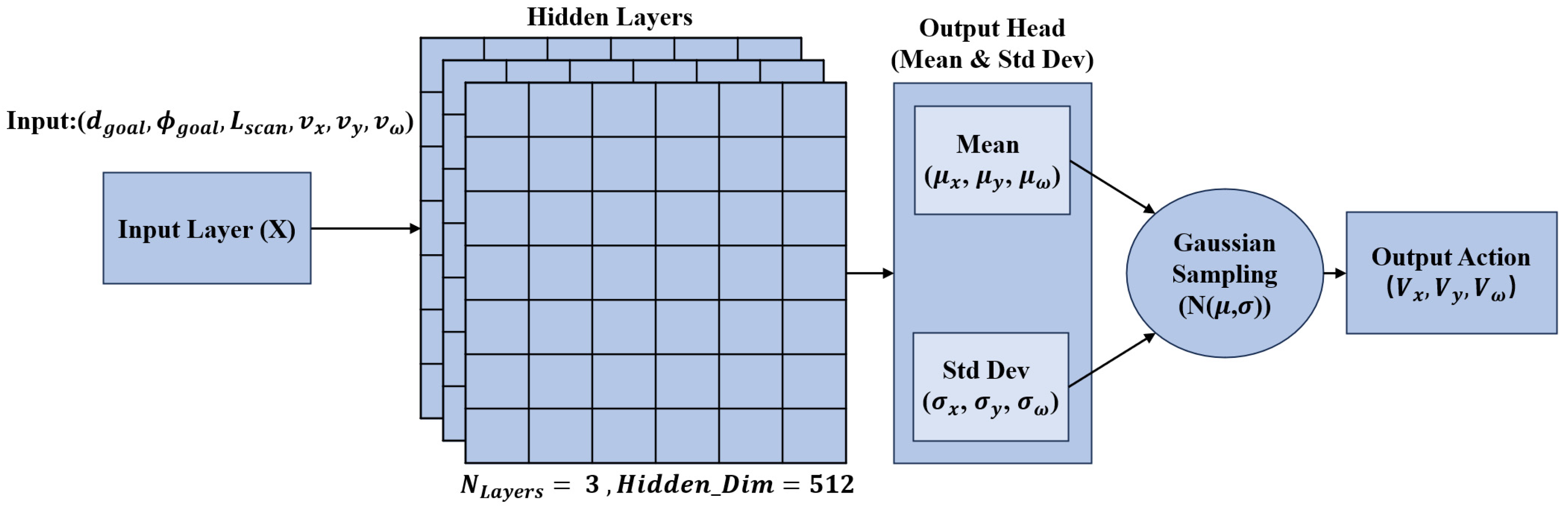
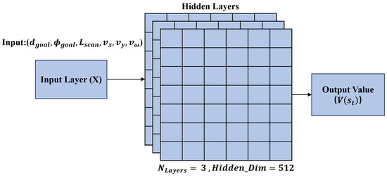
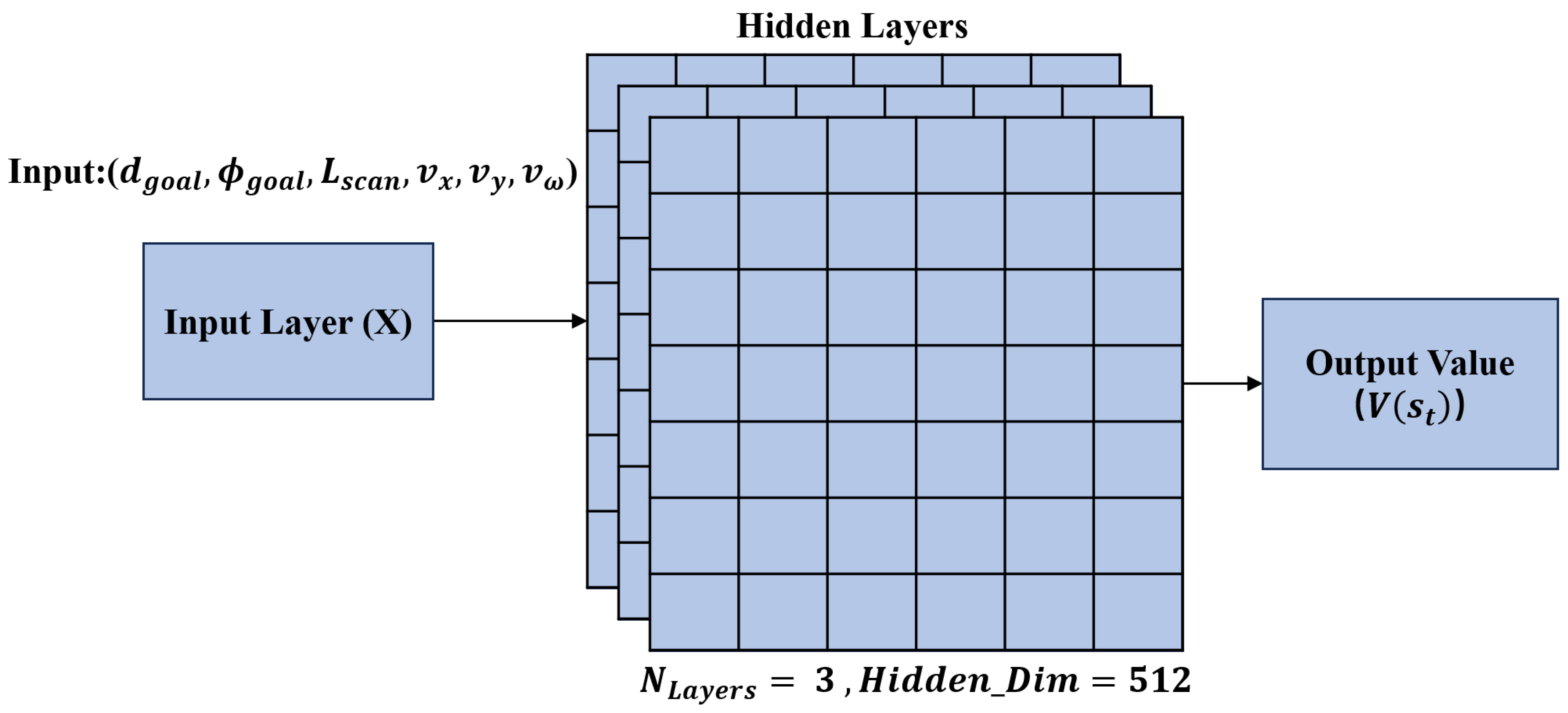
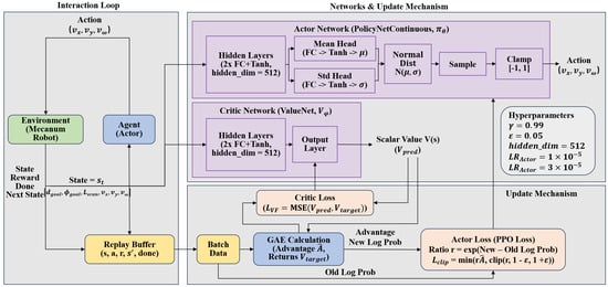
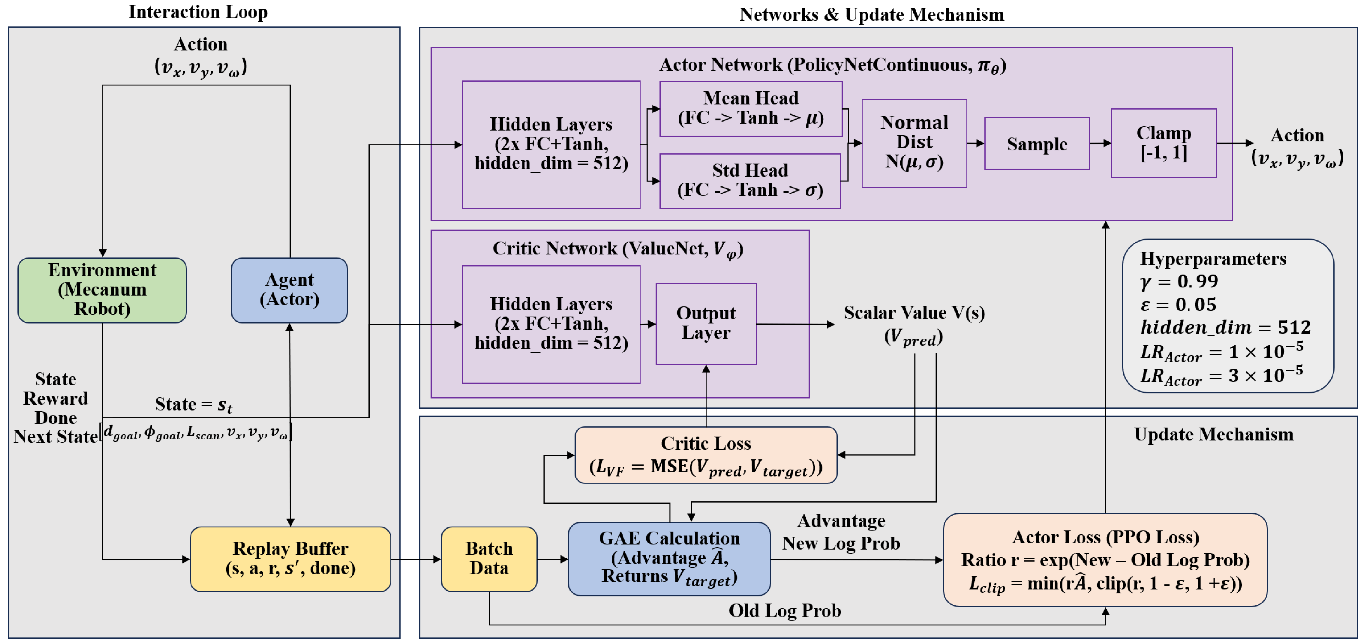
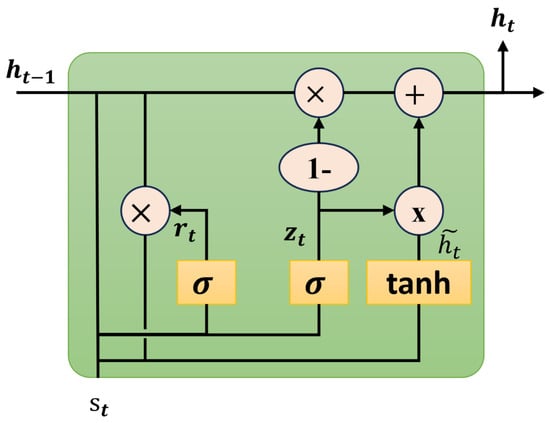
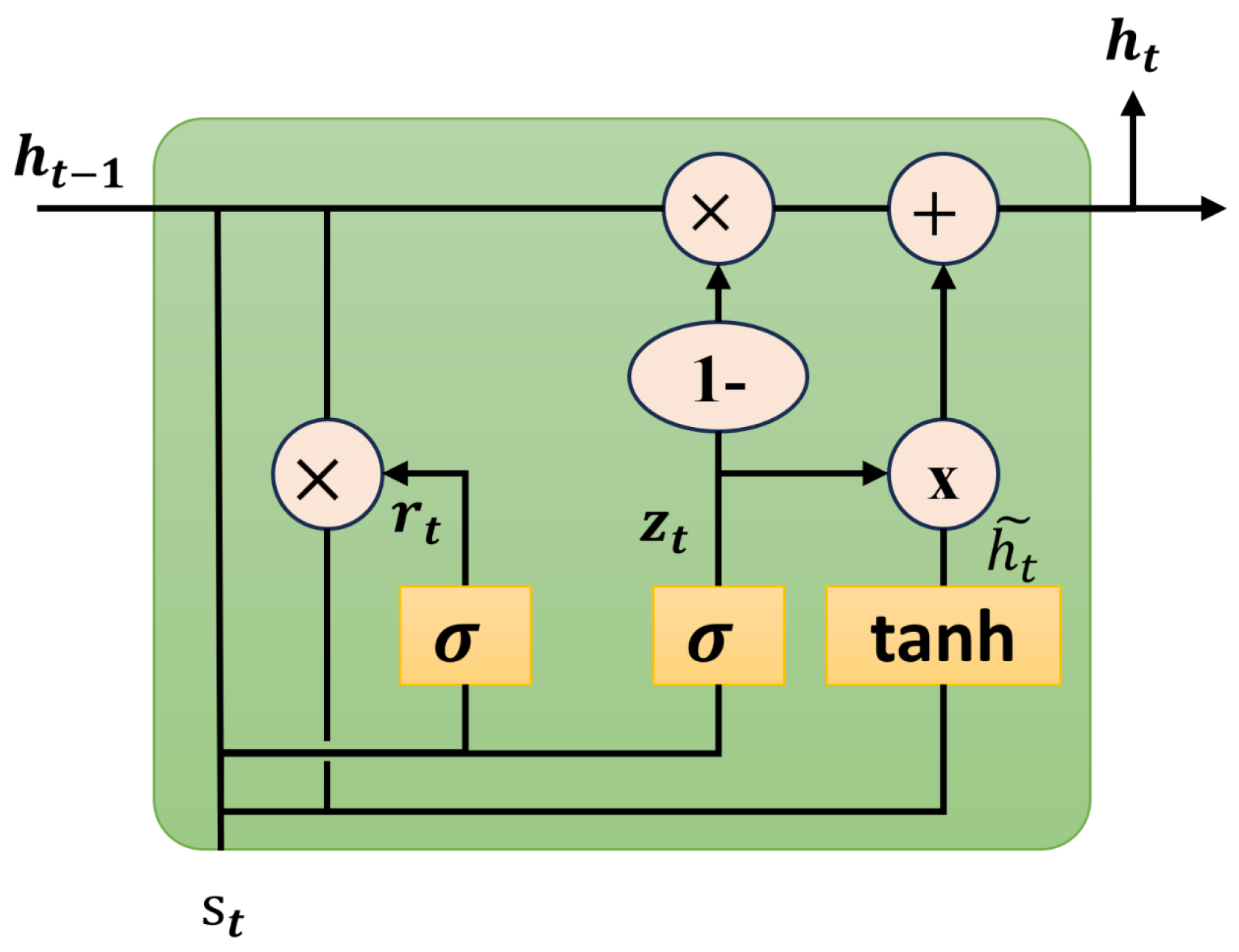
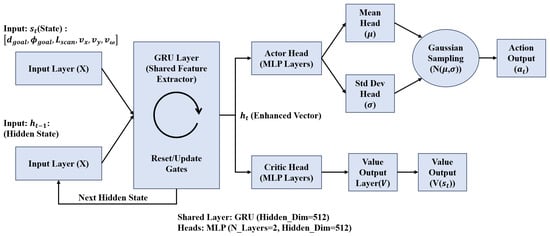
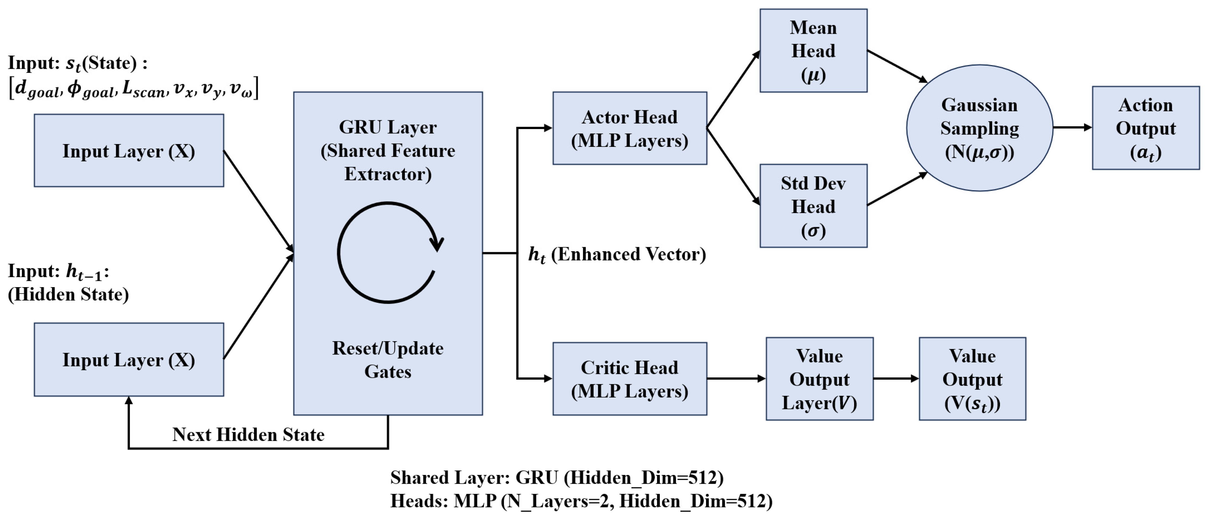
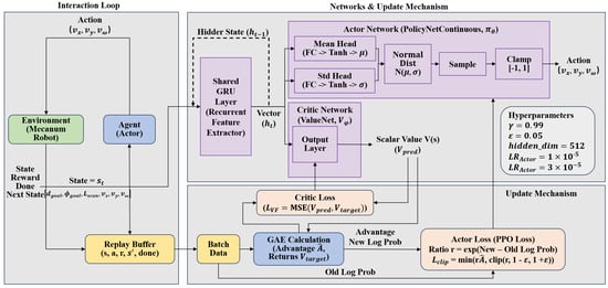
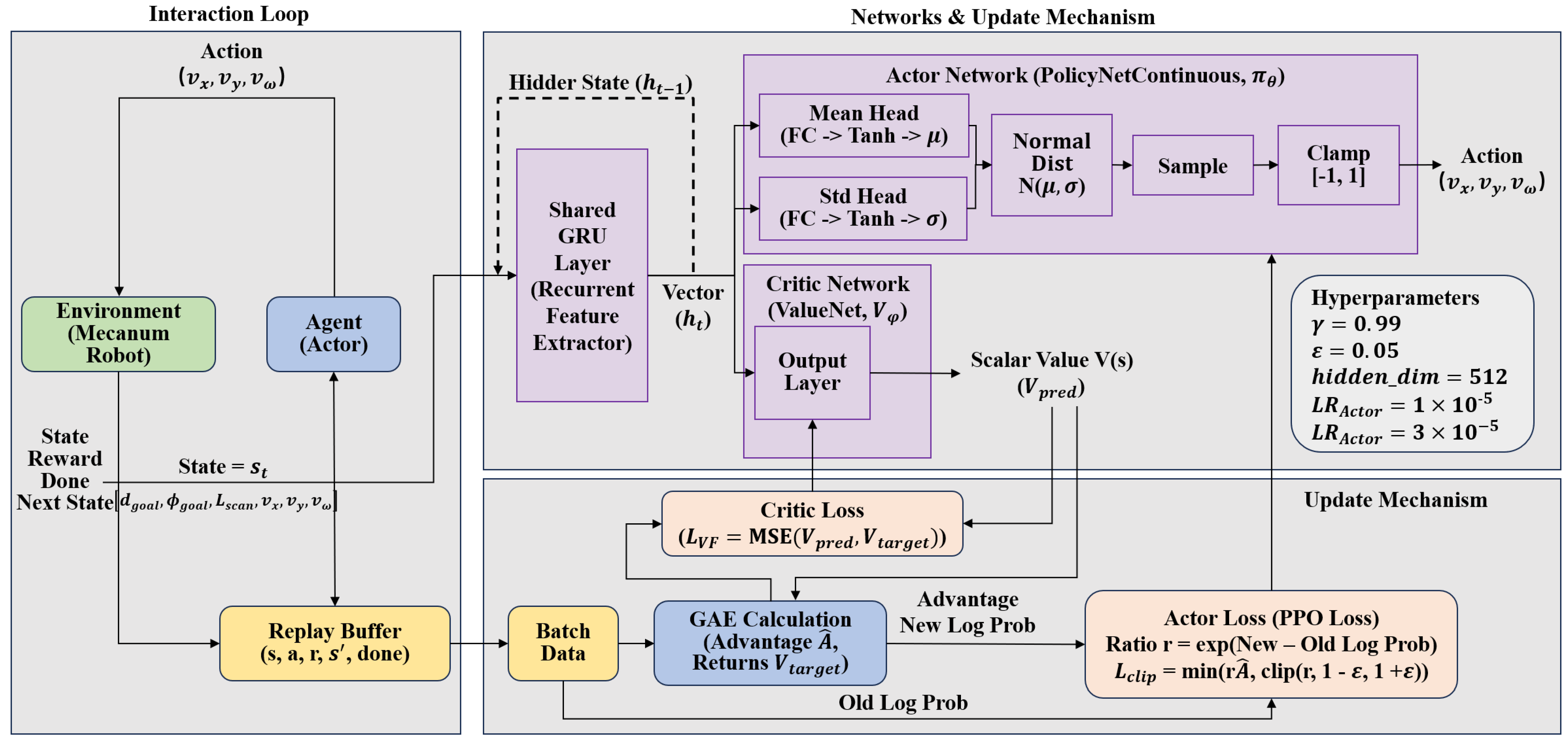
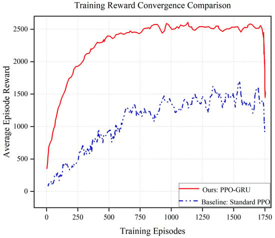
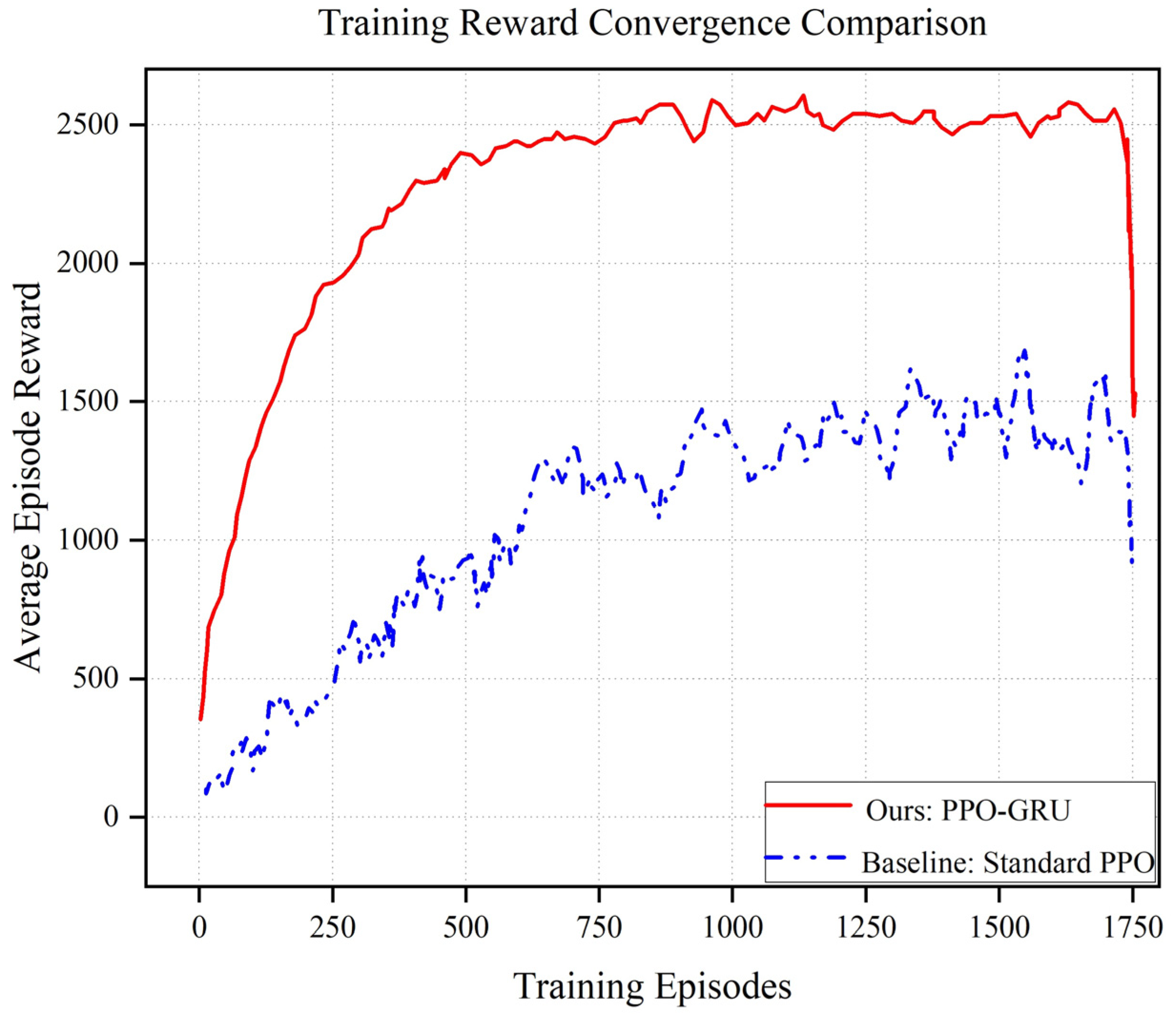
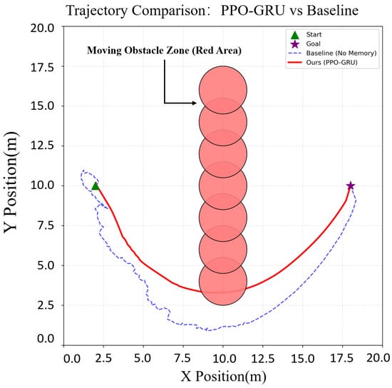
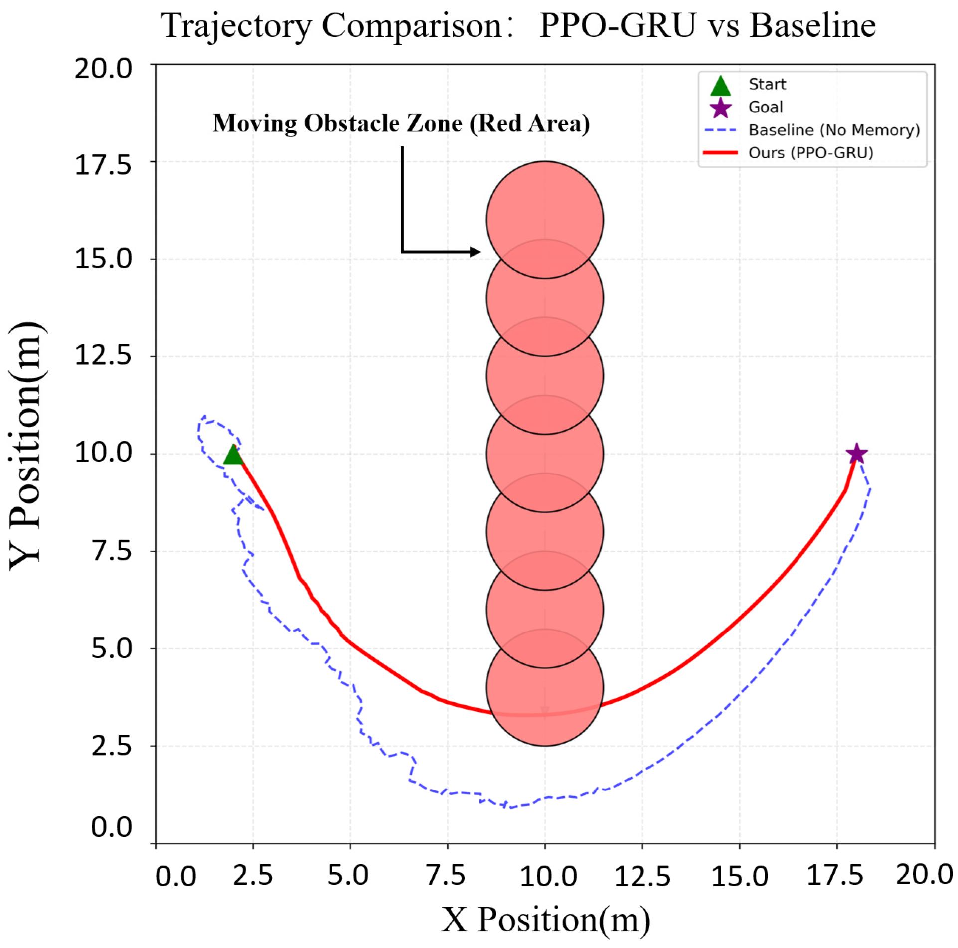
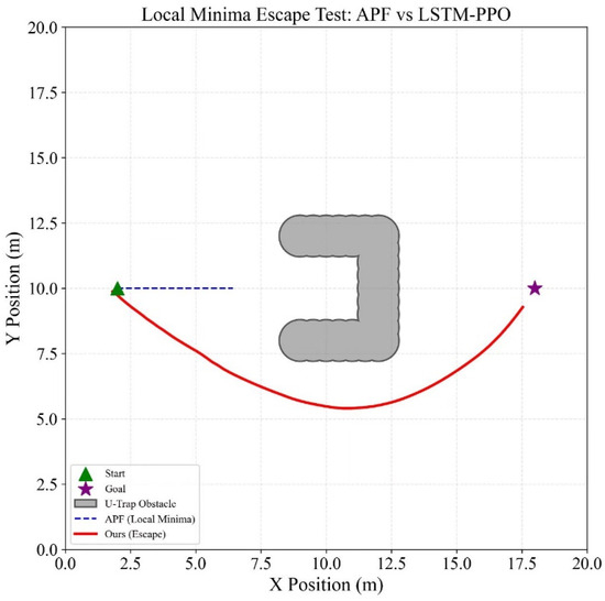
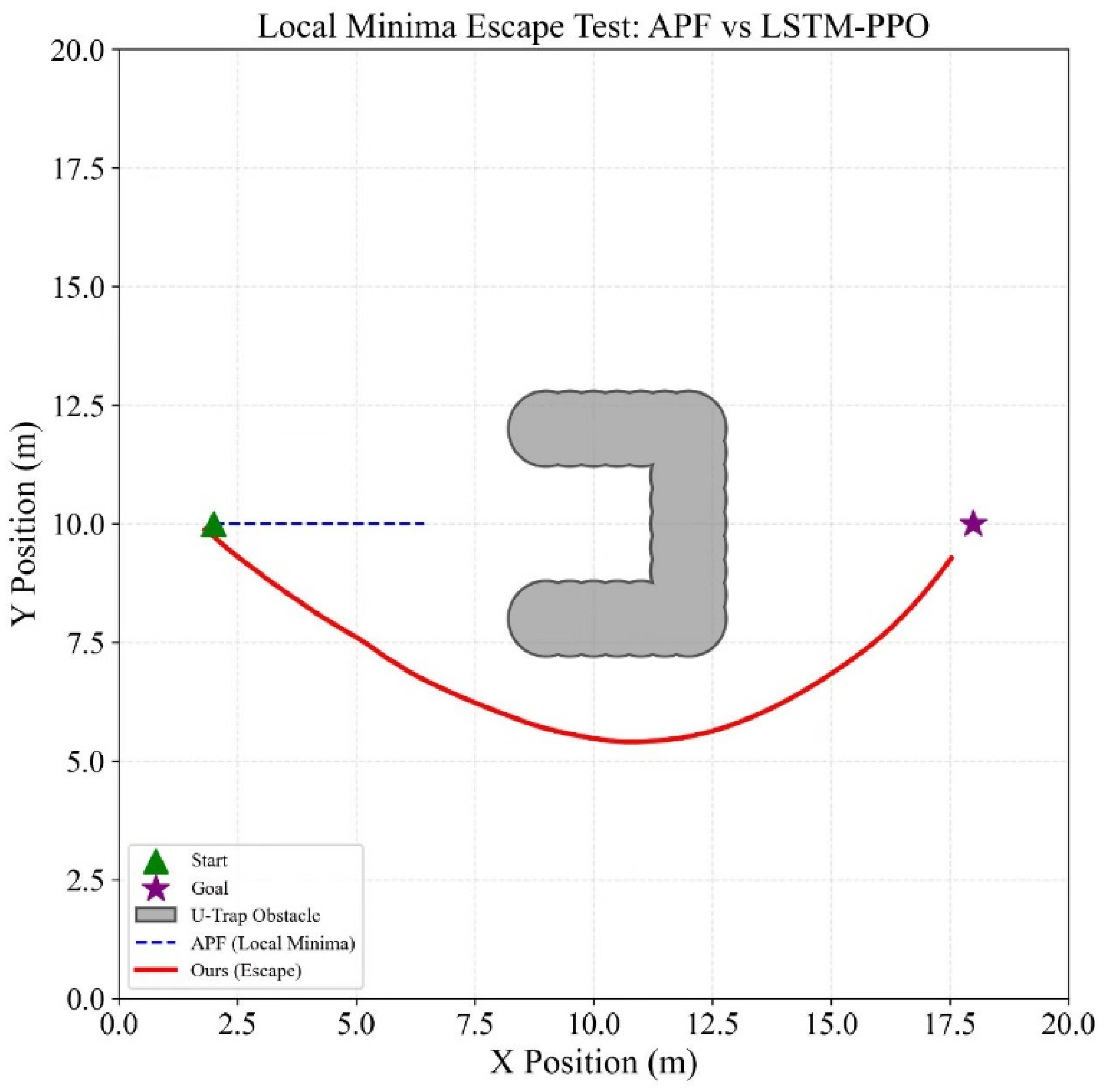
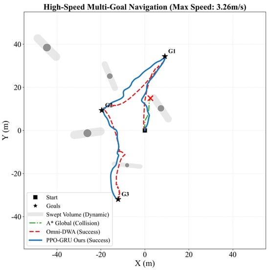
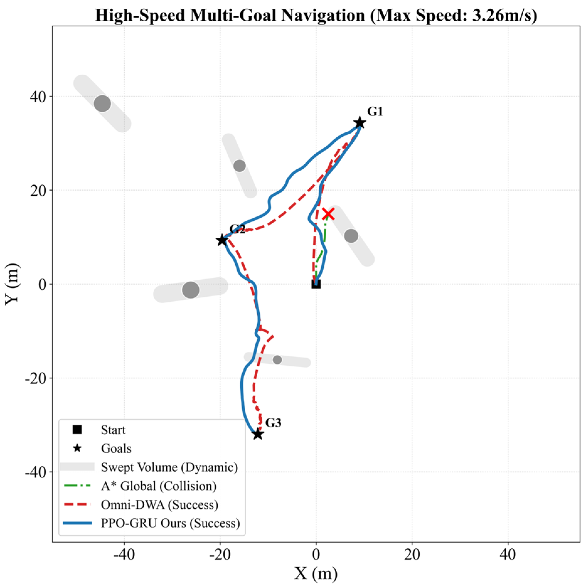
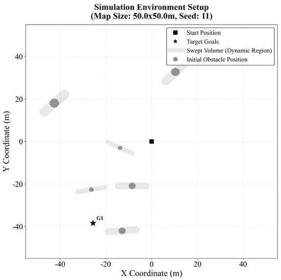
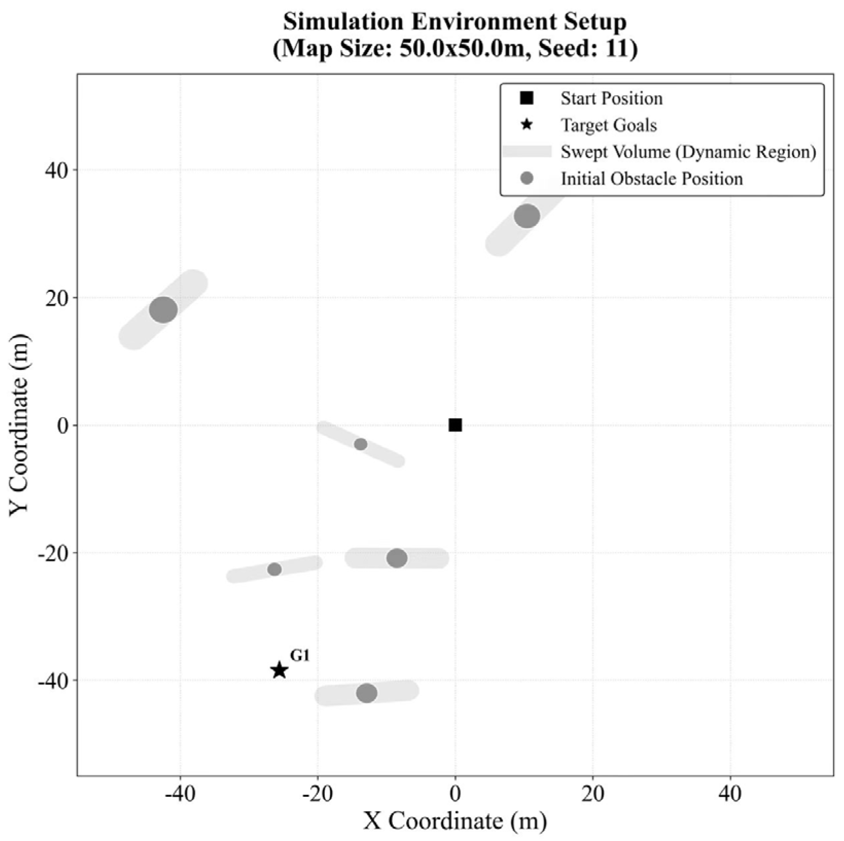
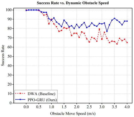
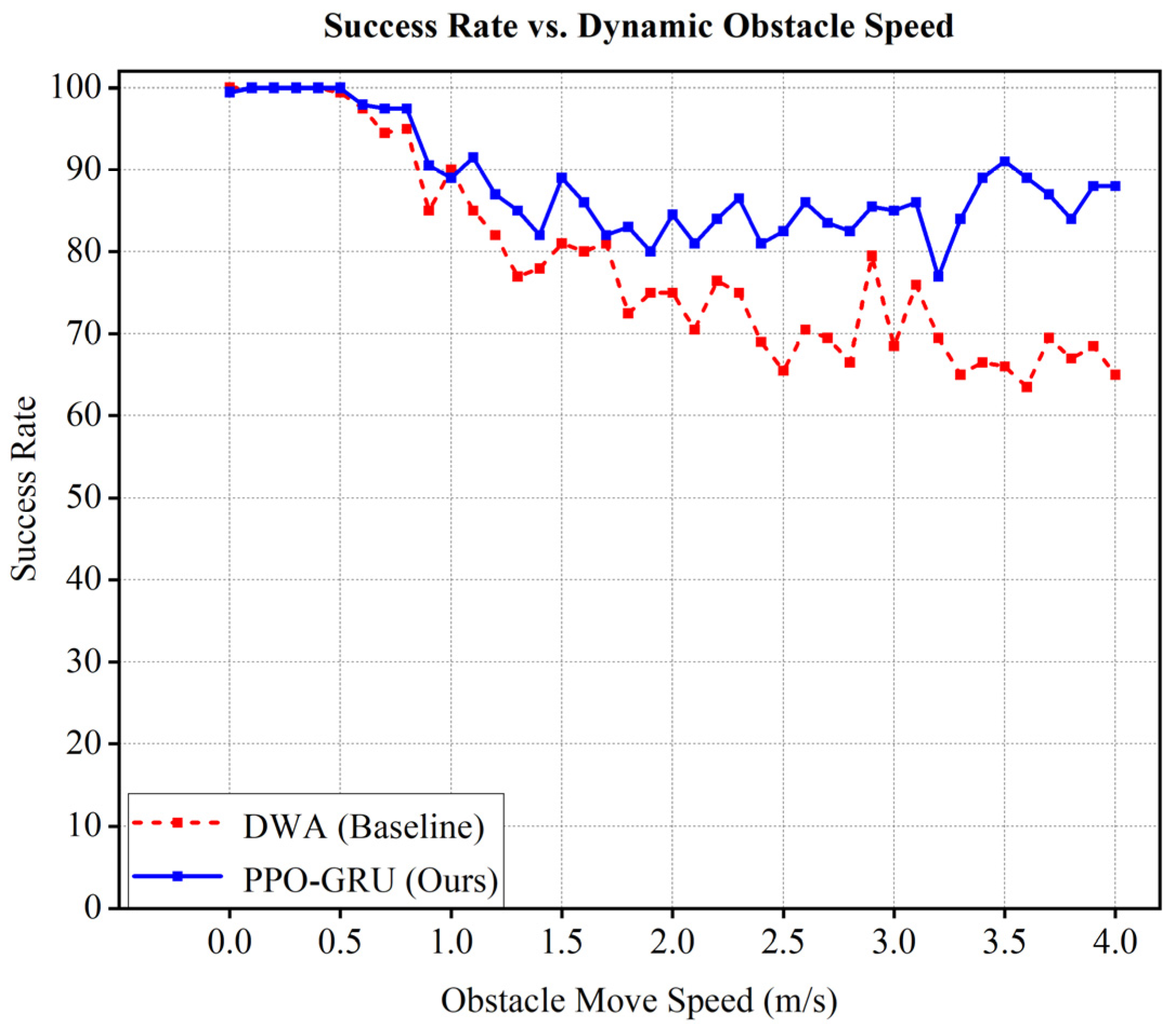
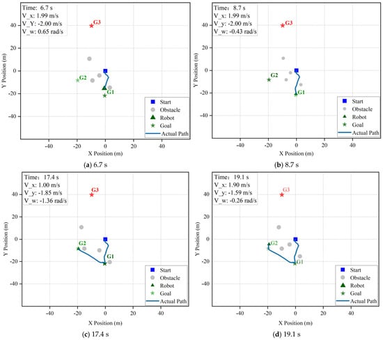
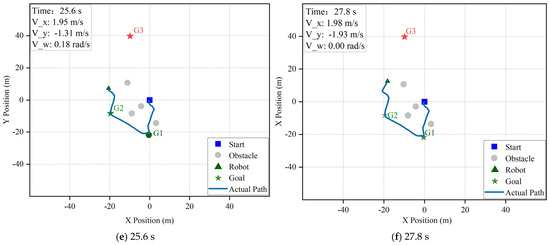
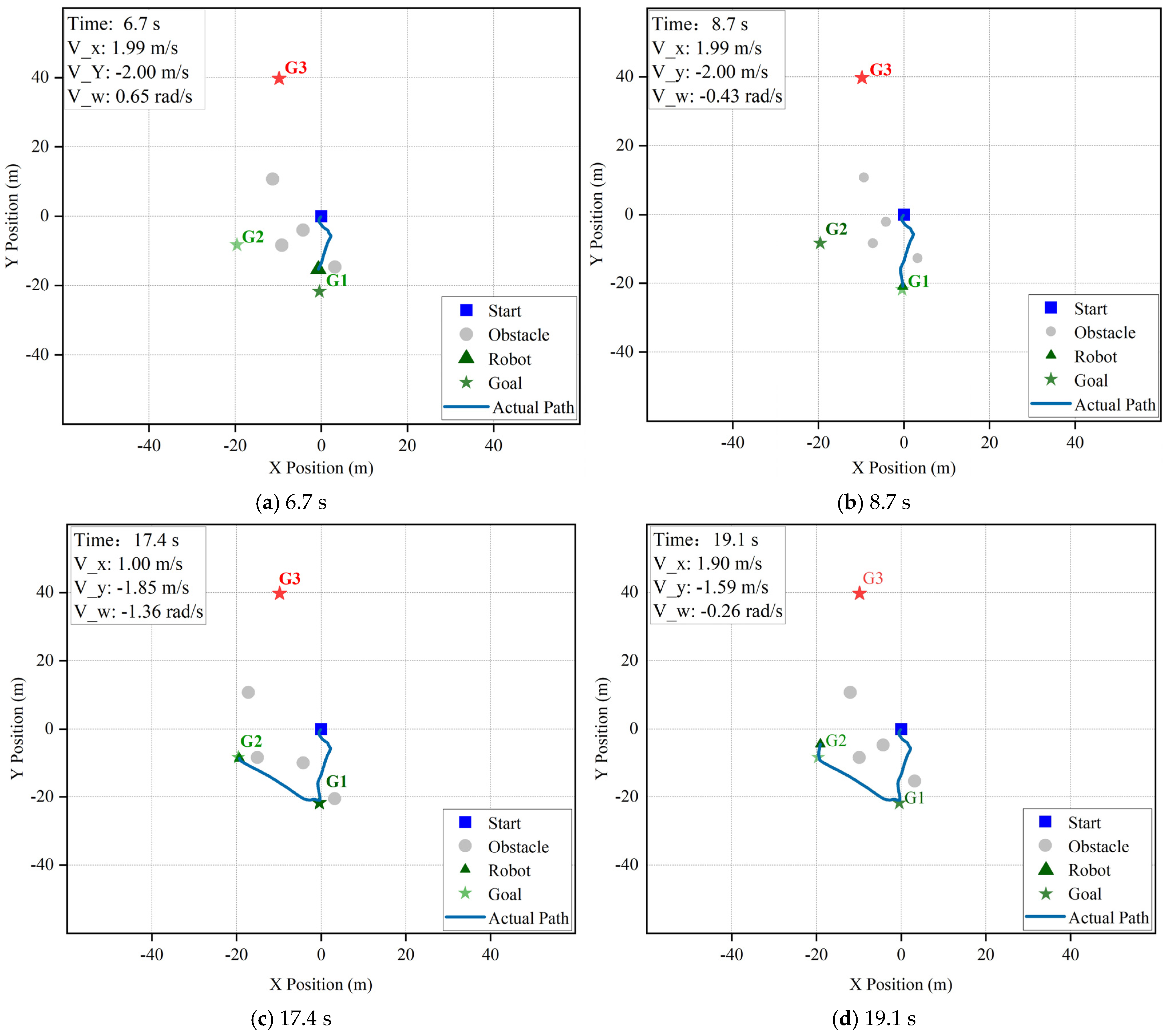
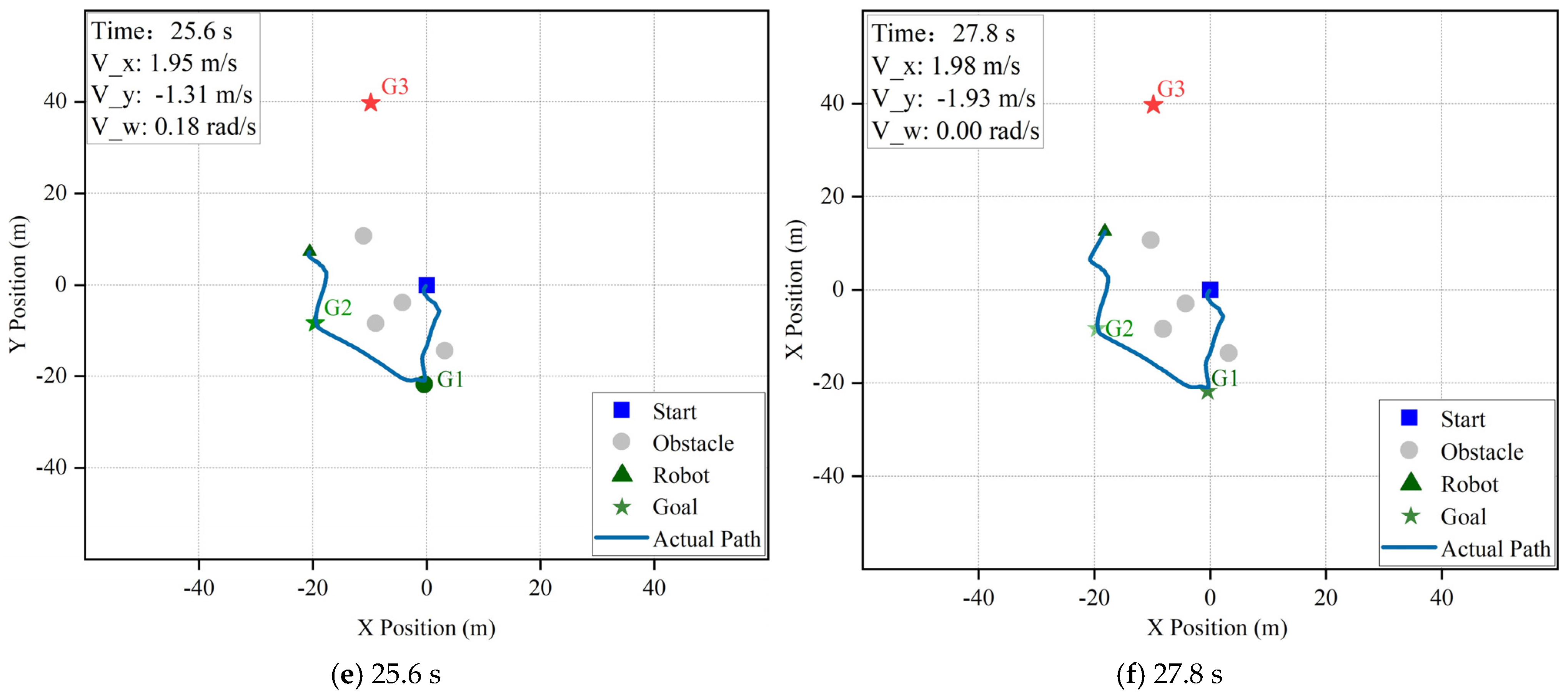
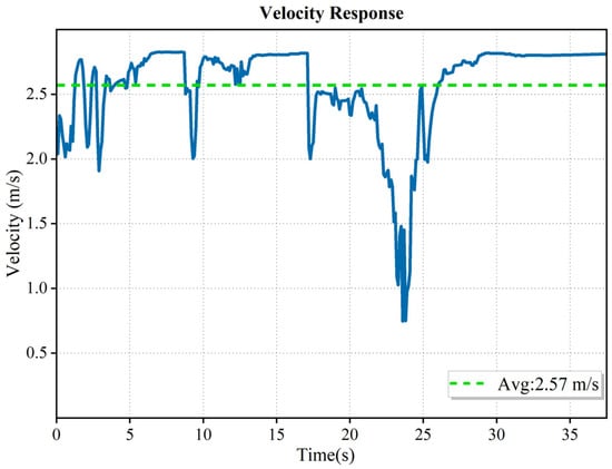
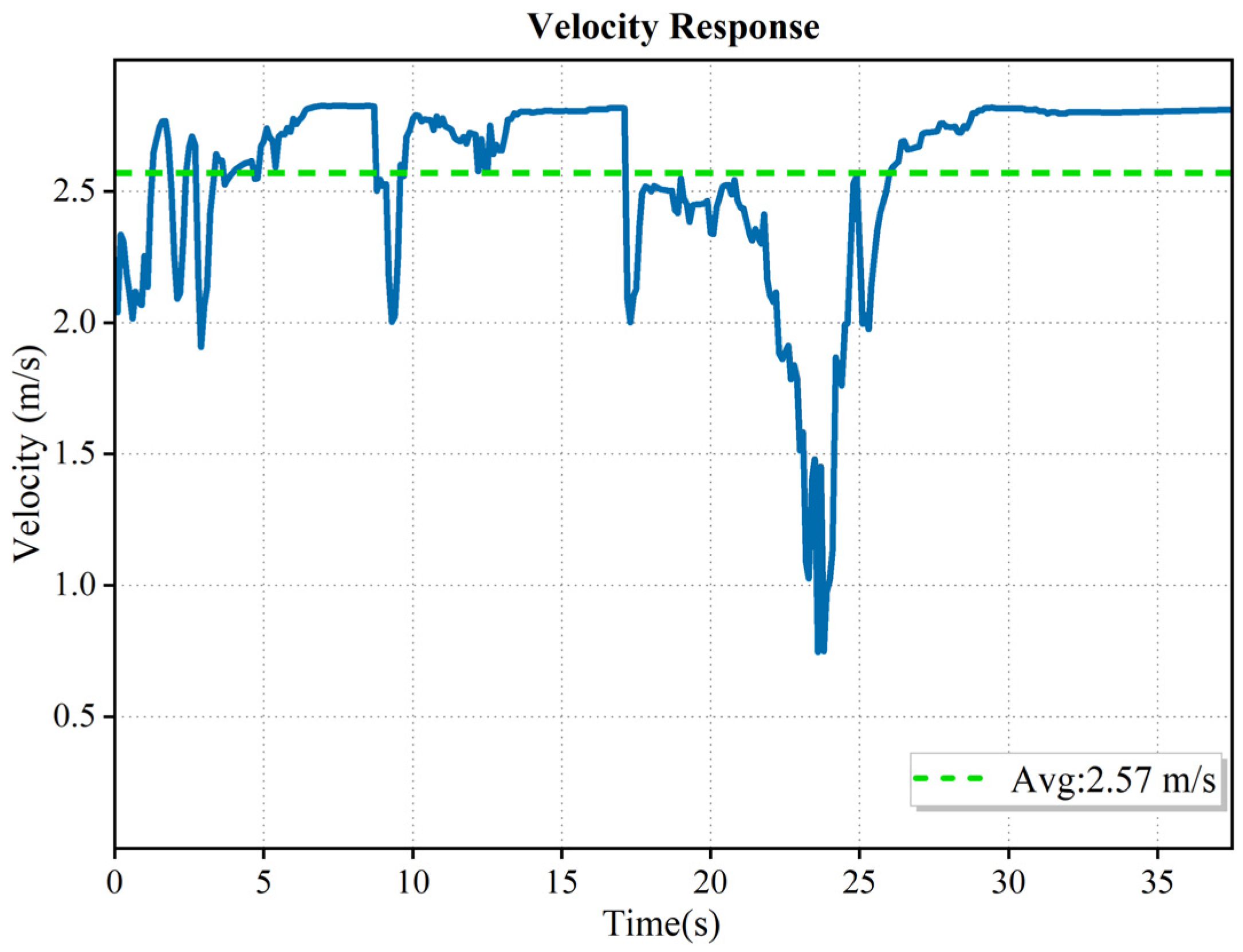
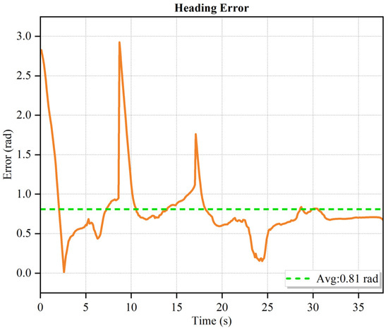
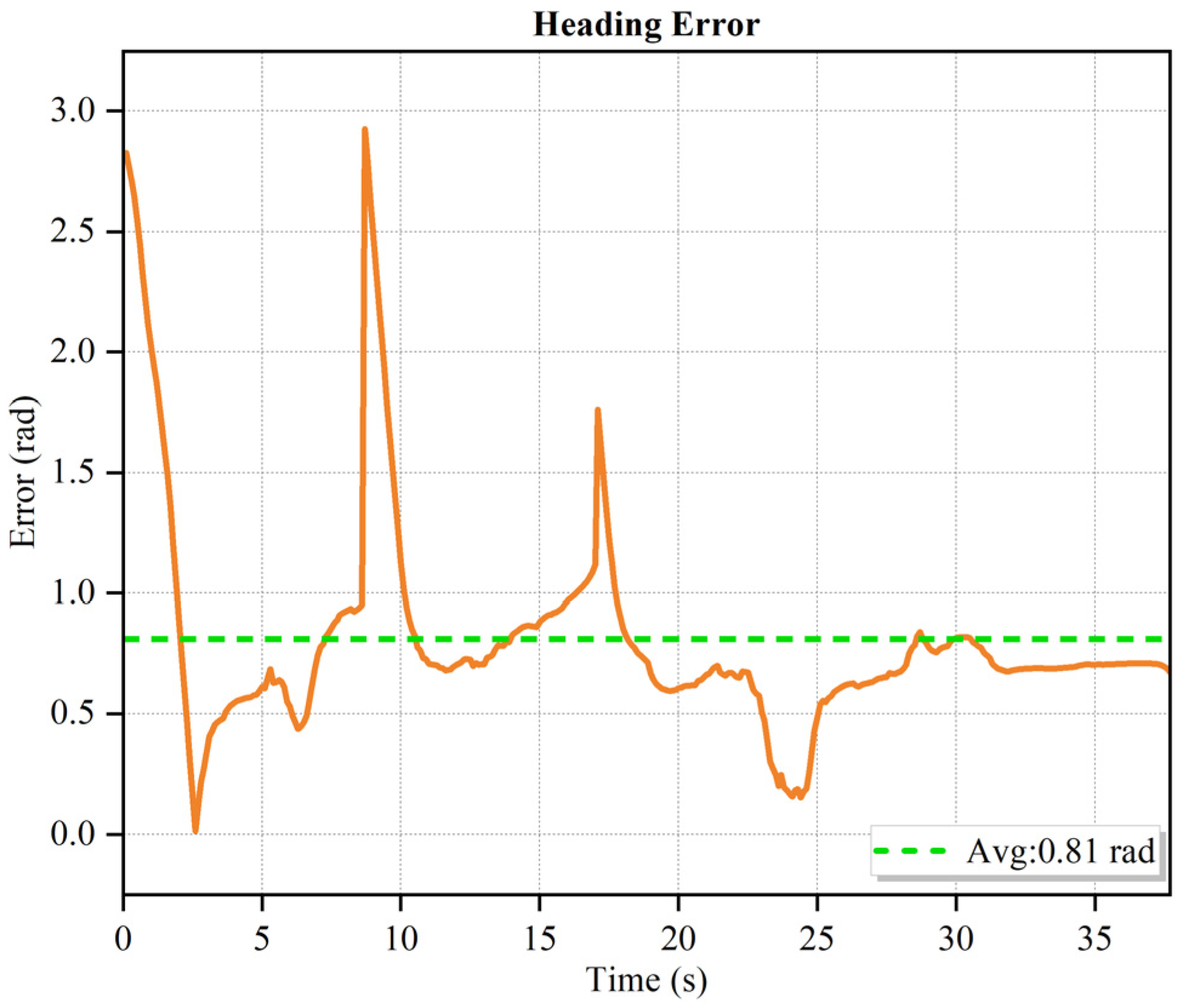
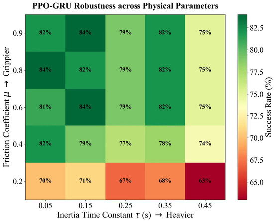
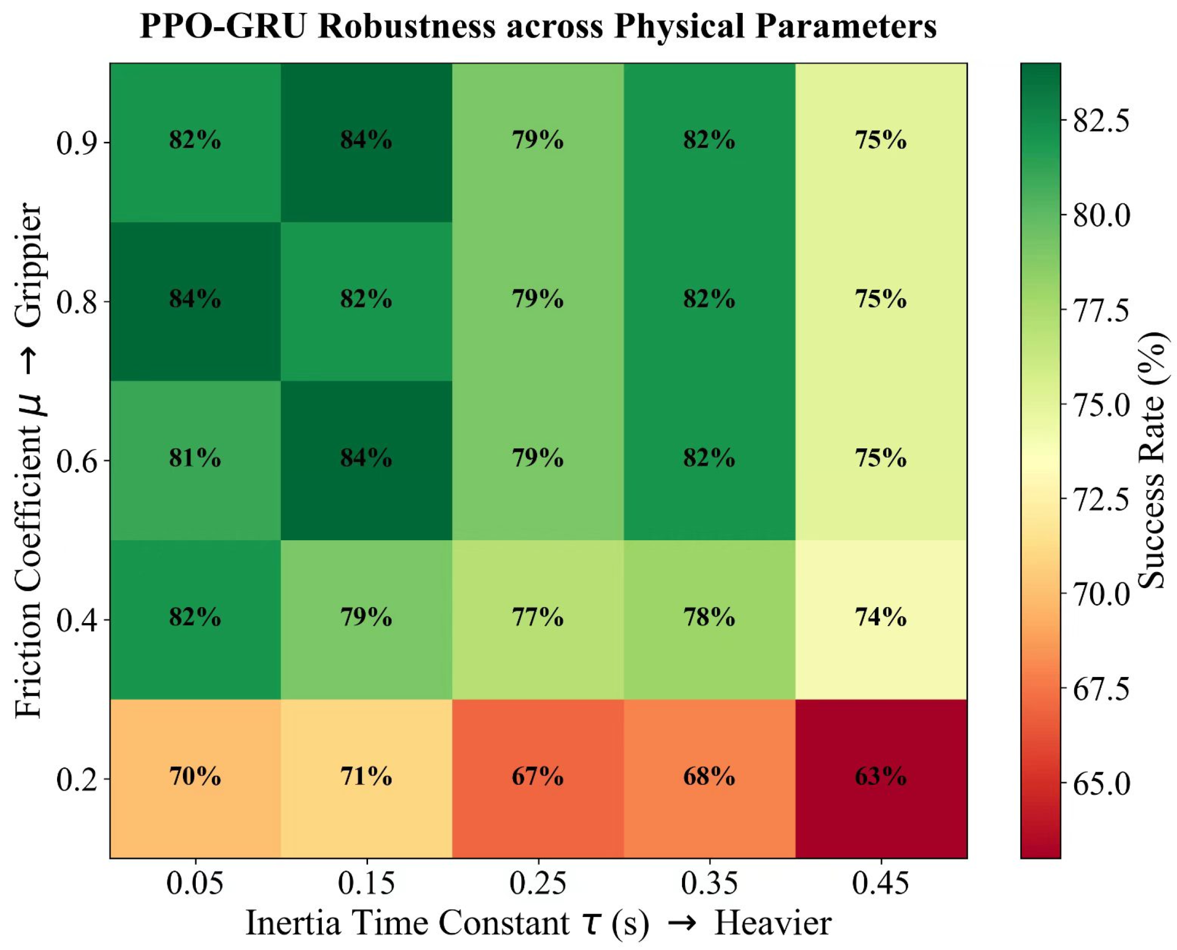
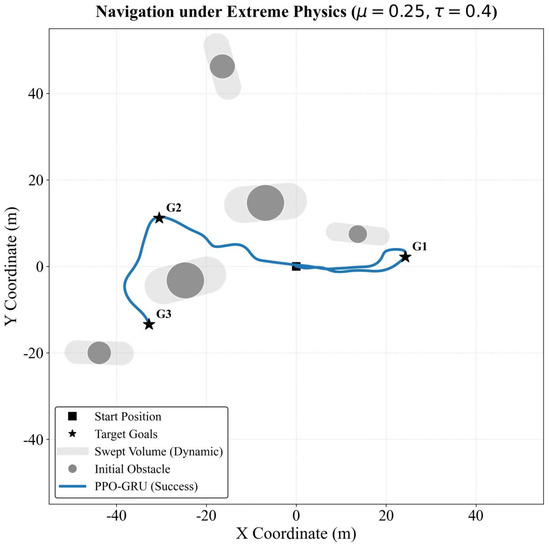
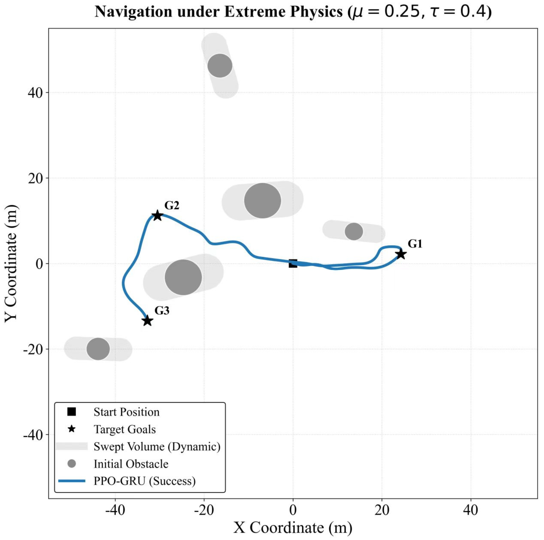
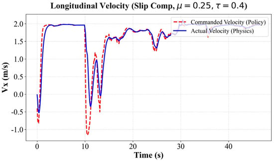
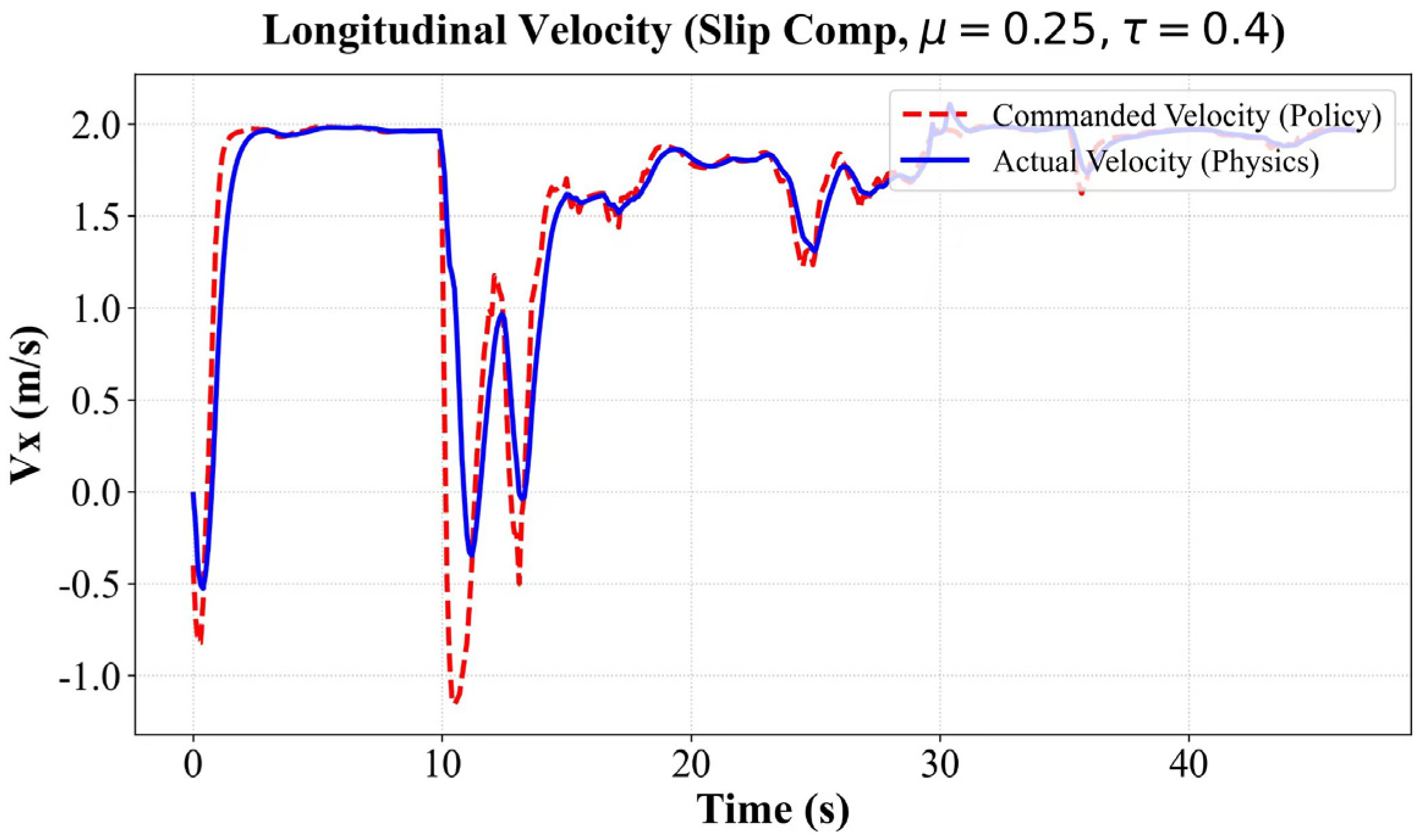
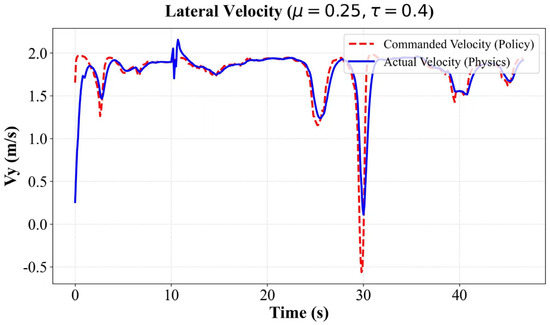
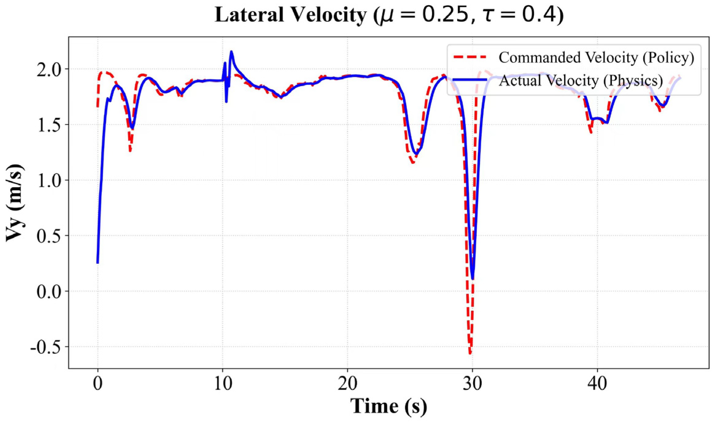
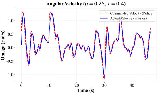
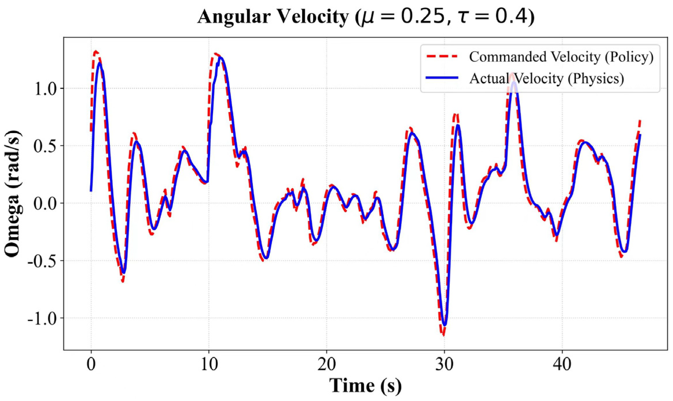

Disclaimer/Publisher’s Note: The statements, opinions and data contained in all publications are solely those of the individual author(s) and contributor(s) and not of MDPI and/or the editor(s). MDPI and/or the editor(s) disclaim responsibility for any injury to people or property resulting from any ideas, methods, instructions or products referred to in the content. |
© 2026 by the authors. Licensee MDPI, Basel, Switzerland. This article is an open access article distributed under the terms and conditions of the Creative Commons Attribution (CC BY) license.