


Abstract
Ocean Thermal Energy Conversion (OTEC) is a promising renewable energy technology for remote islands, offshore platforms, and maritime infrastructure, yet its commercialization is constrained by low cycle efficiency, high auxiliary energy demand, and the engineering challenges associated with large-scale seawater transport. This study presents the integration and experimental evaluation of a 20 kW class containerized OTEC prototype using R134a in a closed Rankine cycle. The working fluid circulates within the power-generation module, while warm surface seawater supplies the evaporator and cold deep seawater is pumped through an insulated intake pipe to the container-mounted condenser. The prototype integrates a radial-inflow turbine, stainless-steel heat exchangers, circulation pumps, and a programmable logic controller-based control system. Land-based commissioning tests, conducted at initial warm-to-cold-water temperature differences of approximately 20–25 °C, produced a peak electrical output of 11 kW in one run and approximately 5 kW for 11 min in another. Sea trials in the South China Sea recorded a peak electrical output of 16.4 kW and a cumulative power-generation duration of 4 h 47 min across separate runs. These results document the integration and short-duration operation of the prototype under offshore conditions and identify priorities for improved control and longer-duration testing.
1. Introduction
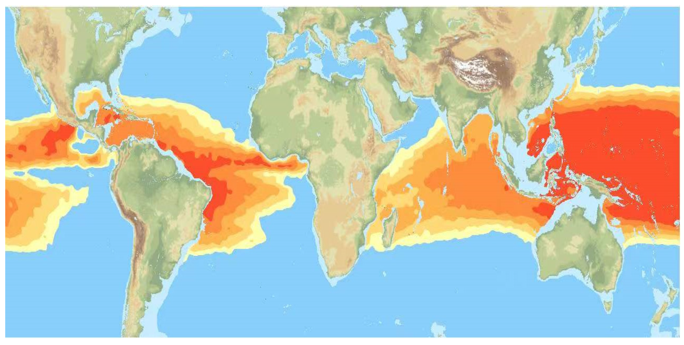
Global energy demand is rising rapidly, while the depletion of fossil fuels and the urgent need to address climate change are driving advances in renewable energy technologies. Oceans, covering approximately 71% of the Earth’s surface [1], store immense amounts of solar energy, with an estimated 80% of incident solar radiation absorbed by seawater annually. This vast energy reservoir includes tidal [2,3], wave [4,5], current [6,7], and ocean thermal energy [8,9], among which ocean thermal energy conversion (OTEC) [10,11,12] is particularly promising due to its high stability, resource abundance, and potential for continuous exploitation independent of weather conditions. The global theoretical potential of ocean thermal energy is estimated at 30 TW, highlighting its promise as a sustainable alternative to traditional fossil fuels [13,14], as shown in Figure 1.
Figure 1.
Global distribution of ocean surface thermal gradients, highlighting equatorial and tropical regions with temperature differences exceeding 20 °C between surface and deep waters. These zones represent the most favorable locations for large-scale OTEC deployment. (From Bluerise BV).
Over the past decades, several countries, including the United States, Japan, France, and Korea, have made significant progress in OTEC research and pilot-scale demonstration. Examples include Japan’s shore-based OTEC plants in Nauru and Kagoshima [15], the 1 MW floating OTEC plant jointly developed by Japan and India [16], and the United States’ 210 kW open-cycle OTEC system in Hawaii [17]. Despite these advances, most systems remain at the demonstration stage and face significant barriers to large-scale deployment, particularly low thermal-cycle efficiency, high pumping energy costs, complex maintenance requirements for long pipelines, and ecological risks from the discharge of deep seawater. China has an extensive maritime domain with abundant ocean energy resources, particularly in the South China Sea, where favorable thermal gradients make it a prime region for ocean thermal energy conversion. Recent assessments estimate that China’s offshore and adjacent waters hold 1.44 × 10²² to 1.59 × 10²² J of ocean thermal energy, corresponding to an installed capacity of 1747 to 1833 GW, with about 90% of this potential located in the South China Sea [18]. However, related research remains largely at the laboratory and small-scale prototype level, and practical solutions for powering remote islands, offshore platforms, and ocean observation systems are urgently needed. Addressing these challenges is critical for strengthening national maritime security, advancing deep-sea resource exploration, and accelerating the transition to renewable energy.
To bridge this research gap, recent studies have explored innovative system designs [19,20], modeling approaches [21,22], and regional feasibility analyses [10,23] to advance OTEC development from concept to practical applications [24,25,26]. These studies offer insights into overcoming technical limitations, improving efficiency, and identifying deployment strategies for various operational scenarios. For instance, Wang et al. [27] developed an OTEC system using phase-change material for underwater vehicles. They built a multi-stage energy conversion efficiency model (thermal-hydraulic-kinetic-electric) to identify key influencing factors and provide optimization guidelines. A prototype was developed and tested in the South China Sea, achieving approximately 6696 J of energy per dive with an overall conversion efficiency of 0.396%, demonstrating the system’s high efficiency and potential for application. Zhang et al. [28] proposed a novel OTEC cycle that integrates a second-type absorption heat pump with a Rankine power cycle to overcome the limitations of low-grade ocean thermal energy by supplying a superheated working fluid at the turbine inlet. Thermodynamic modeling and economic analysis demonstrate that it achieves a 40% improvement in thermal efficiency, up to 68.88% exergy efficiency, and a 38% cost reduction compared to conventional OTEC systems, offering a practical and cost-effective pathway for large-scale ocean thermal energy utilization. Vera et al. [29] developed a detailed model for an OTEC system integrated with an Organic Rankine Cycle (ORC) for small-scale power generation in Panama’s San Blas archipelago, focusing on working fluid selection, system performance, and environmental considerations. Simulation and sensitivity analysis identified ammonia as delivering the highest net power output (99.3 kW), R1234yf as offering the best efficiency (2.57%), and decafluorobutane as an environmentally safe alternative, providing guidelines for OTEC deployment in remote island electrification. Zereshkian et al. [30] assessed the feasibility of using OTEC to supply power to offshore oil and gas fields in the Caspian Sea by analyzing 10 years of meteorological and oceanographic data. Results show that OTEC is only feasible during summer months in select southern locations, offering 31–54 operational days annually. Adiputra et al. [31] presented the preliminary design of a 100 MW-net OTEC floating power plant for Mentawai Island, Indonesia, using a converted oil tanker as the platform to reduce capital costs. A combination of Monte Carlo simulation and constraint satisfaction methods was applied to optimize plantship dimensions, seawater transport velocity, and equipment layout, concluding that a Suezmax-type tanker with seawater transport velocities of 2–3 m/s offers an optimal balance of space, buoyancy, and energy efficiency for commercial-scale OTEC deployment.
Building on these studies, the present work focuses on the engineering implementation and experimental evaluation of a containerized OTEC prototype. A 20 kW-class prototype using R134a was developed based on a closed Rankine cycle. The design, construction, and overall sea-trial performance of this prototype were reported in our previous study [32]. The present study further describes the containerized system integration, instrumentation, working-fluid selection, and the operating problems observed during land-based commissioning and offshore testing. The working fluid circulates within the power-generation module, while warm surface seawater is supplied to the evaporator and cold deep seawater is pumped through an insulated intake pipe to the container-mounted condenser. The system incorporates a radial-inflow turbine, brazed stainless-steel heat exchangers, and a programmable logic controller-based monitoring and control system. The paper presents the design basis and component configuration, describes the containerized integration and shipboard deployment, and reports representative land-based and offshore operating records. Particular attention is given to startup procedures, electrical-output variations, and the liquid-level and vibration-related problems encountered during testing. The contribution lies in documenting the implementation and operating limitations of the integrated prototype, providing an experimental basis for subsequent improvements in control and mechanical reliability.
2. System Overview
2.1. Limitations of Conventional OTEC Systems
OTEC systems harness the temperature gradient between warm surface seawater, typically 25–30 °C, and cold deep seawater, approximately 4–6 °C at depths of 800–1000 m, to drive a thermodynamic cycle and generate electricity. Conventional OTEC systems generally employ a Rankine [33,34,35] or Kalina [17,36,37] cycle, in which seawater is supplied to shore-based or platform-mounted equipment for heat exchange. The small available temperature difference limits cycle efficiency, while seawater pumping contributes to auxiliary power consumption. Long cold-water intake pipes also introduce installation and maintenance challenges associated with marine currents, wave action, and biofouling. Deep-seawater discharge is a further consideration because it can affect local temperature and nutrient distributions. These limitations motivate engineering evaluation of the heat exchangers, turbines, seawater supply system, and their operation as an integrated prototype.
2.2. Working-Fluid Circulation and Seawater Circulation Configuration
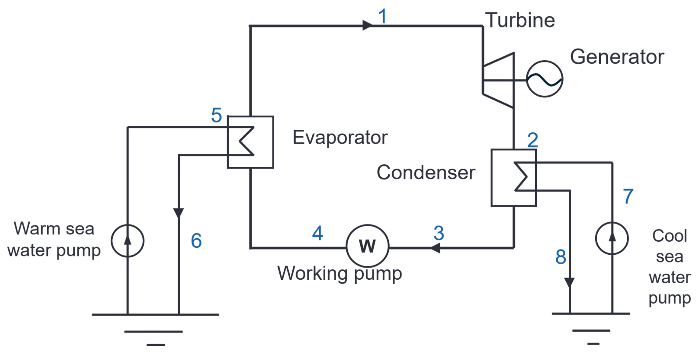
The prototype employs R134a in a closed Rankine-cycle loop, as illustrated in Figure 2. The working fluid circulates through the evaporator, turbine, condenser, and working-fluid pump within the power-generation module. Warm surface seawater is supplied to the evaporator by the warm-water pump. In the offshore configuration, deep seawater is lifted through the insulated intake pipe by a submersible pump to a cold-water tank and is subsequently supplied to the container-mounted condenser by the cold-water circulation pump. Both seawater streams are discharged after heat exchange. The closed working-fluid loop is therefore separate from the seawater intake and discharge circuits; the working fluid does not circulate between the surface and deep-water layers.
Figure 2.
Simplified schematic of the closed-Rankine-cycle OTEC prototype, showing the working-fluid loop and the warm- and cold-seawater streams.
2.3. Thermodynamic Cycle Analysis
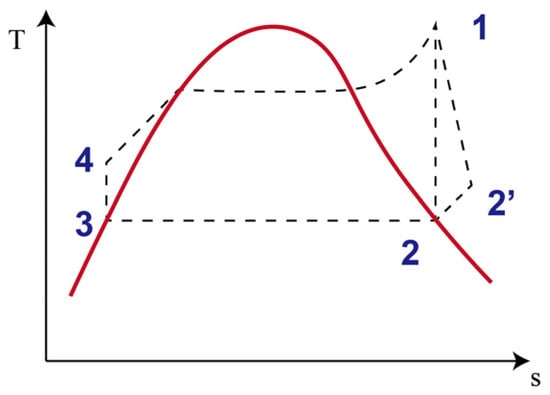
This section provides an overview of the working-fluid circulation cycle, illustrated in Figure 3, which shows the temperature-entropy (T-s) diagram and the key thermodynamic processes of the proposed OTEC system.
Figure 3.
Temperature-entropy (T-s) diagram of the closed Rankine cycle. The diagram illustrates four key thermodynamic processes: heat addition through liquid heating, evaporation, and superheating (4 → 1), expansion (1 → 2; actual 1 → 2′), condensation (2 → 3), and compression (3 → 4).
- (1)
- Cycle description:
Heating, evaporation, and superheating (4 → 1): In the evaporator, the pressurized liquid working fluid is first heated to the saturated-liquid state, then vaporized at approximately constant temperature and pressure, and finally superheated before entering the turbine.
Expansion (1 → 2, actual 1 → 2′): The superheated vapor ideally undergoes isentropic expansion in the low-pressure turbine, converting enthalpy into mechanical work. In practice, irreversibility caused by flow friction, leakage, and blade losses shifts the process to path 1 → 2′, resulting in a lower enthalpy drop, higher outlet temperature, and reduced turbine efficiency. This distinction between ideal and actual expansion is crucial for accurate cycle evaluation and performance optimization.
Condensation (2 → 3): The exhaust vapor releases latent heat in the condenser, transferring energy to deep cold seawater. Efficient condensation is essential for achieving low exhaust pressure and maintaining a strong driving temperature gradient. Proper condenser design and seawater management are vital to minimize thermal resistance and maintain cycle stability.
Compression (3 → 4): The liquid working fluid is pumped back to high pressure, closing the cycle. Although this process consumes relatively little energy compared to turbine output, minimizing pump losses and ensuring operational reliability are key to improving overall system efficiency, particularly in low-temperature-gradient applications.
- (2)
- Key performance metrics:
The thermodynamic design calculation adopts the following assumptions. The working fluid enters the turbine in a superheated state to reduce liquid-droplet formation during expansion. Heat losses from the insulated evaporator and condenser to the surroundings are neglected. The ideal turbine process is treated as isentropic expansion, while the actual process includes irreversible losses. The working fluid at the condenser outlet is assumed to be saturated liquid, and the working-fluid pump process is simplified as adiabatic compression.
Thermal efficiency:
Net power output:
- (3)
- Working-fluid selection:
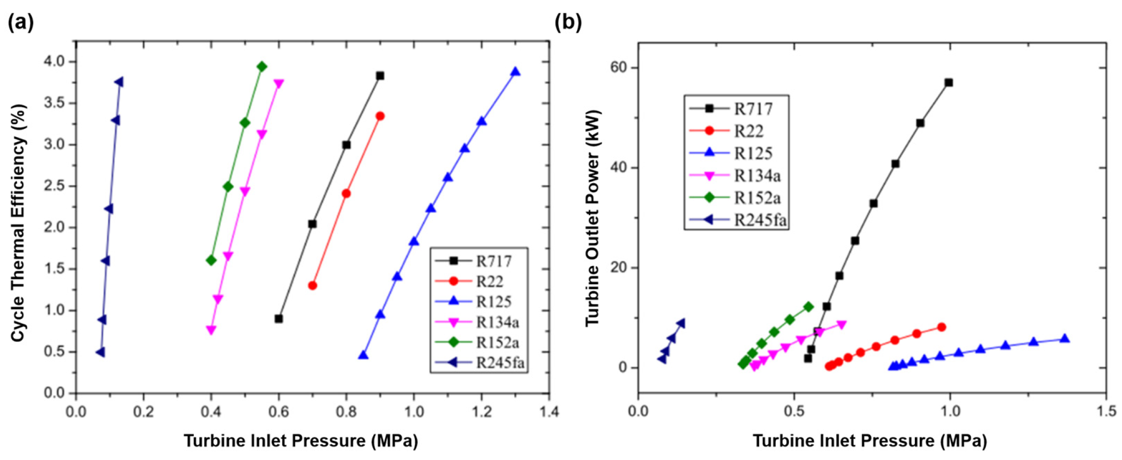
The thermophysical properties of the candidate working fluids, including molar mass, critical temperature, and critical pressure, were obtained from the CoolProp thermophysical property database and are summarized in Table 1. Figure 4a shows the calculated cycle thermal efficiency as a function of turbine inlet pressure for an evaporation temperature of 26 °C and a condensation temperature of 6 °C. Within the pressure ranges investigated, the thermal efficiency increases with turbine inlet pressure for each fluid, with R152a reaching the highest efficiency among the plotted cases.
Table 1.
List of candidate working fluids with chemical abbreviations and key thermophysical properties, including molar mass, critical temperature, and critical pressure.
Figure 4.
Calculated performance of the candidate working fluids as a function of turbine inlet pressure: (a) cycle thermal efficiency at an evaporation temperature of 26 °C and a condensation temperature of 6 °C; (b) turbine power output at a working-fluid mass flow rate of 1 kg/s, a specified turbine inlet temperature of 25 °C, and a condensation temperature of 6 °C.
Figure 4b presents a separate comparison of turbine power output at a working-fluid mass flow rate of 1 kg/s, with a specified turbine inlet temperature of 25 °C and a condensation temperature of 6 °C. R717 reaches the highest calculated turbine power output among the investigated cases. This result concerns turbine power output rather than cycle thermal efficiency, and the two quantities should therefore be distinguished when evaluating working-fluid performance.
Working-fluid selection also considered the material compatibility, sealing, and operational safety requirements of the prototype. Although R717 provided favorable turbine power output, its toxicity and flammability, together with material-compatibility concerns, imposed additional requirements on system implementation. R134a was therefore selected by considering the calculated cycle performance together with these practical requirements, rather than solely maximizing thermal efficiency or turbine power output.
2.4. System Layout Design
The system is divided into four functional subsystems:
- (1)
- Evaporation zone: The evaporator transfers heat from warm surface seawater to the working fluid.
- (2)
- Power generation zone: The radial-inflow turbine expands the working-fluid vapor to produce mechanical power.
- (3)
- Condensation zone: The container-mounted condenser transfers heat from the turbine exhaust to the supplied deep seawater. The condensed working fluid is collected in the refrigerant receiver before being returned to the working-fluid pump.
- (4)
- Control and pumping system: The working-fluid and seawater pumps provide the required circulation. Their operating frequencies and the main and bypass valve openings are adjustable through the control system. The PLC acquires operating signals and communicates with the monitoring interface.
The main process equipment is housed in an equipment container and is operated from a separate monitoring container. Deep seawater is supplied through the insulated intake system. The equipment specifications, component analyses, and deployment arrangement are described in the following sections.
3. System Design and Technical Roadmap
The development of the prototype follows a structured framework that integrates thermodynamic design, component selection and fabrication, containerized assembly, land-based commissioning, and offshore testing. The power-generation module integrates the evaporator, radial-inflow turbine-generator, condenser, refrigerant vapor-liquid separator, circulation pumps, and PLC control cabinet. The 20 kW designation corresponds to the rated power of the selected generator, rather than the measured full-system net electrical output. To provide a consolidated description of the prototype, the principal design specifications of the main components and subsystems are summarized in Table 2. These values represent the design or rated parameters of the prototype rather than the measured operating conditions of individual tests.
Table 2.
Main design specifications of the 20 kW class OTEC prototype.
The component-level design focused on the radial-inflow turbine, brazed plate heat exchangers, and the deep-water intake system used in the prototype. Emphasis is placed on engineering design, prototyping, and experimental validation to address performance challenges and guide system development.
System-level design efforts focus on creating a highly integrated, containerized power-generation module that houses all major components, thereby reducing construction complexity and facilitating standardization. Finally, the integrated prototype underwent land-based commissioning followed by offshore testing.
The system is based on a closed-loop Rankine cycle that employs the low-boiling-point working fluid R134a as the energy carrier. In this configuration, the working fluid is vaporized in the evaporator using warm surface seawater, expanded through a radial-inflow turbine, and condensed in the container-mounted condenser using cold seawater supplied through the deep-water intake pipe. The operational loop is divided into functional subsystems, including evaporation, expansion, condensation, and pumping-control modules, which provide the required heat transfer, expansion, condensation, and circulation functions.
The turbine and heat exchanger are key components of the integrated prototype. A radial-inflow turbine with a rated rotational speed of 12,000 rpm was used in the prototype. Brazed stainless-steel heat exchangers were used as the evaporator and condenser. The working fluid loop operates at a turbine inlet pressure of approximately 0.62–0.64 MPa, with a pump power of about 3.7 kW.
The cold-water intake system, another critical subsystem, is designed as a 900 m long insulated steel pipe. A 50 mm polyurethane insulation layer was applied to the cold-water intake pipe to reduce heat gain during seawater ascent. The structural design conditions and calculated safety factor are described in Section 4.2.
All major components, including the turbine, pumps, control systems, and heat exchangers, are integrated into a containerized platform to facilitate transportation, assembly, and offshore installation. The power-generation module is housed in an equipment container measuring 6.0 × 2.5 × 2.6 m, while the control container measures 6.0 × 2.5 × 3.2 m. Dimensions are given as length × width × height. Strong and weak electrical circuits are separated to prevent signal interference, and external insulation with aluminum cladding provides additional durability and corrosion resistance in marine environments. The integrated layout was used for the subsequent land-based and offshore tests.
The technical roadmap advances through a sequence of experimental validation phases. Initial land-based testing was conducted under controlled conditions using refrigeration units and gas boilers to simulate ocean temperature gradients. During the land-based commissioning tests, temperature, pressure, turbine speed, pump and valve settings, and electrical output were monitored to evaluate startup and power-generation behavior. Following the land-based commissioning tests, sea trials were carried out in the South China Sea, where the system was deployed at sites characterized by stable thermoclines with deep-water temperatures of approximately 5 °C at a depth of 900 m. The sea trials evaluated the deep-water intake system, startup procedure, control operation, and electrical-output behavior under offshore conditions. Based on these findings, the system design is now being refined to improve turbine internal-flow performance, thermal management, and control strategies.
4. Key Component Design and Analysis
The successful implementation of a working-fluid-circulation OTEC system relies heavily on the development of high-performance components that operate efficiently under low temperature differentials and in challenging offshore environments. This section focuses on the heat exchangers, deep-water intake pipe, and integrated prototype configuration. Their designs and associated calculations are presented below, while the prototype operating results are reported in Section 5.
4.1. Heat Exchanger Design
Efficient heat exchangers are critical for minimizing irreversibility in the evaporation and condensation processes of the working fluid cycle. The prototype used brazed stainless-steel heat exchangers as the evaporator and condenser. The thermodynamic design specified a heat-transfer requirement of approximately 800 kW for the evaporator and condenser.
4.2. Cold-Water Pipe Structure and Insulation Design
The cold-water intake pipe was designed to transport deep seawater at approximately 5 °C from a depth of about 900 m to the surface. The pipe system used steel tubing with a 50 mm polyurethane insulation layer to reduce heat gain during seawater ascent. Because the test vessel lacked a derrick and a conventional casing make-up system, adjacent pipe sections were connected using split-clamp couplings with conical mating ends, a sealing groove, and four connecting bolts. The split-clamp coupling configuration enabled pipe assembly during the offshore deployment process.
In the pre-trial structural analysis, a vertical load of 100 t was applied to the cold-water pipe system. The lateral loading was calculated using a maximum seawater current velocity of 1.25 m/s, corresponding to an applied pressure of 1.67 × 10⁻³ MPa. The calculated maximum equivalent stress was 509.2 MPa at the clamp transition region. For the 35CrMo clamp material, with a yield strength of 835 MPa, the corresponding stress safety factor was approximately 1.64. The calculated maximum total deformation was 93.084 mm.
4.3. System Integration and Prototype Validation
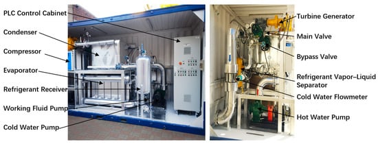
The turbine, heat exchangers, and piping network were integrated into a containerized prototype for land-based commissioning and offshore testing (Figure 5). The seawater piping components were fabricated from 316L stainless steel to ensure high corrosion resistance, while the electrical subsystems employed a strong-weak current-separation design to minimize electromagnetic interference. The containerized system consolidates the evaporator, condenser, turbine-generator unit, liquid-vapor separator, and auxiliary pumps into a compact, modular platform, facilitating transportation, installation, and standardized testing. Land-based commissioning tests were conducted using refrigeration units and gas boilers to supply cold and warm water. During land-based commissioning, one representative run reached a peak electrical output of 11 kW, while another produced approximately 5 kW for about 11 min. The turbine and heat exchangers were operated during the offshore power-generation tests described in Section 5. These tests provided operating data for the integrated prototype under offshore conditions.
Figure 5.
Containerized OTEC prototype system used for land-based and sea trials. The left image shows the complete integrated power module with its control cabinet, condenser, evaporator, and pumps, while the right image provides a detailed view of the turbine-generator and auxiliary subsystems.
5. Experimental Validation and Results
To evaluate the operation of the integrated 20 kW-class containerized OTEC prototype, a series of land-based commissioning tests and offshore trials was conducted. Testing proceeded in two stages: laboratory-based testing under controlled conditions, followed by open-sea trials in the South China Sea. These tests provided operating records of temperature, pressure, flow rate, turbine speed, electrical output, and shutdown events under the investigated conditions.
5.1. Land-Based Prototype Testing
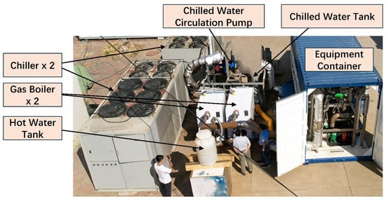
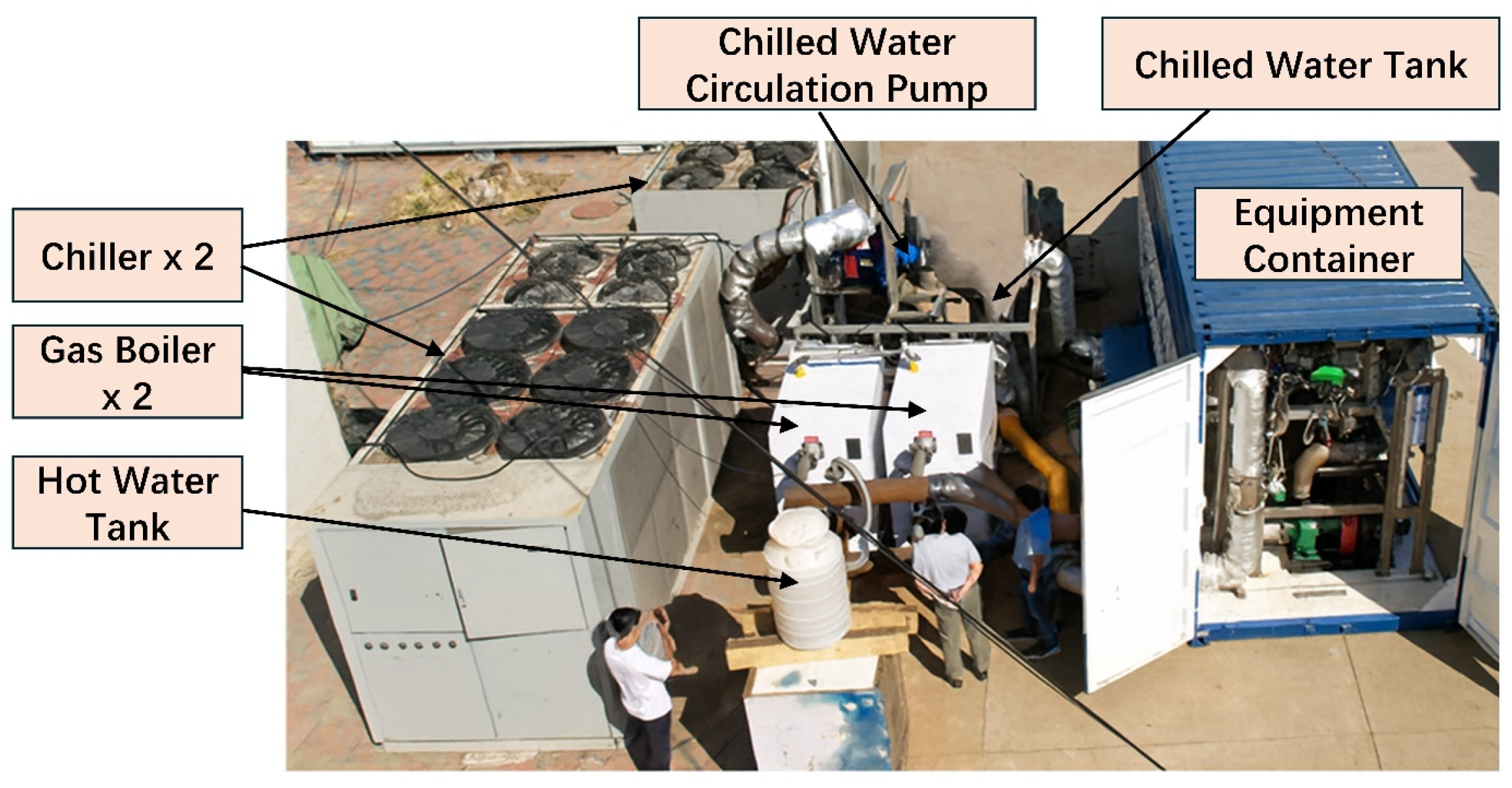
The land-based experiments were conducted to replicate the ocean thermal gradient under controlled conditions, enabling preliminary validation of the working-fluid-circulation OTEC system. As demonstrated in Figure 6, the test platform included two refrigeration units (chillers) to generate cold water on land, two gas boilers for warm-water heating, together with insulated storage tanks and circulation pumps, to provide controlled warm- and cold-water conditions for land-based commissioning. The containerized power generation module, comprising the turbine-generator, heat exchangers, and pump systems, was integrated into this setup, while a PLC-based control system provided real-time monitoring and automated operation. The measurement system included 13 pressure transmitters with a measurement range of 0.1–2.0 MPa, 16 Pt100 temperature sensors with a measurement range of 0–100 °C, a vortex flowmeter for the working-fluid line, electromagnetic flowmeters for the warm- and cold-water loops, a turbine-speed encoder, two vibration probes, and a liquid-level sensor. The measurement ranges and nominal accuracies of the principal instruments are summarized in Table 3. This experimental configuration offered a reliable environment for evaluating component performance and refining control strategies prior to offshore deployment.
Figure 6.
Land-based prototype testing platform for the working-fluid circulation OTEC system.
Table 3.
Measurement instruments and specifications used in the prototype tests.
Initial startup tests included pump priming, valve actuation, and controlled turbine acceleration by adjusting the working-fluid pump frequency and the main and bypass valve openings. During the first run, when the turbine speed exceeded 9000 rpm, the generator torque setting was increased to limit the rotational speed. In one representative run, the initial warm- and cold-water inlet temperatures were 26.9 °C and 6.1 °C, respectively, and the pressure difference across the turbine was 0.21 MPa.
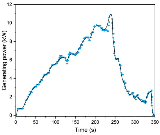
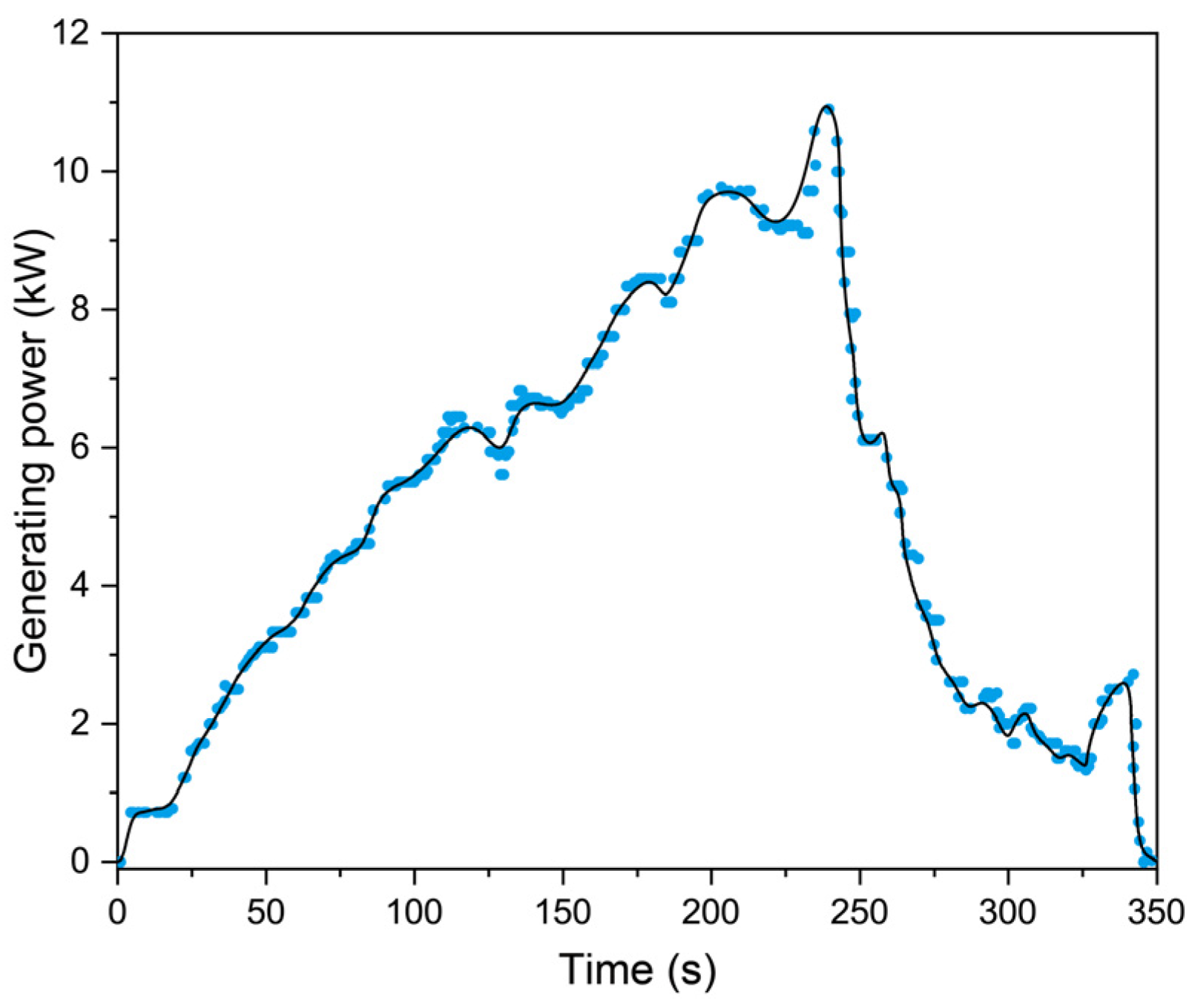
Figure 7 shows the recorded electrical output during this run. The run lasted approximately 5 min and reached a peak electrical output of 11 kW. As the cold-water inlet temperature increased to 9.8 °C, the refrigerant-receiver liquid level fell to approximately 250 mm. The working-fluid pump then stopped automatically, and power generation ceased.
Figure 7.
Recorded electrical output during the first representative land-based run, with initial warm- and cold-water inlet temperatures of 26.9 °C and 6.1 °C, respectively, and a pressure difference of 0.21 MPa across the turbine.
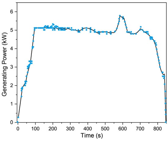
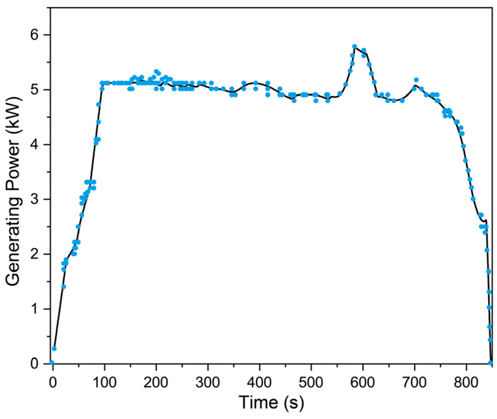
A second test started with warm- and cold-water inlet temperatures of 28.5 °C and 4.1 °C, corresponding to an initial temperature difference of 24.4 °C. In this experiment, as shown in Figure 8, the turbine speed varied between approximately 7000 and 8000 rpm during the early stage of the test, with an electrical output of approximately 5 kW. After approximately 4 min, the cold-side temperature increased and the turbine speed began to decrease. The working-fluid pump frequency, cold-water pump frequency, main-valve opening, and bypass-valve opening were then adjusted to maintain the turbine speed above approximately 7000 rpm for a further period. When the cold-side temperature reached approximately 9.9 °C, the turbine speed and refrigerant-receiver liquid level decreased rapidly, and power generation stopped. The two runs were commissioning tests conducted with different turbine pressure differences, valve openings, turbine speeds, and subsequent control adjustments; therefore, they do not constitute a controlled comparison of temperature difference alone.
Figure 8.
Measured electrical output during the second representative land-based commissioning run, conducted with a 24.4 °C thermal gradient (28.5 °C warm-side, 4.1 °C cold-side). The run lasted approximately 11 min, during which the turbine speed varied around 7000–8000 rpm and the electrical output remained around 5 kW for much of the test before the system shut down as the cold-side temperature increased.
5.2. Sea Trials in the South China Sea
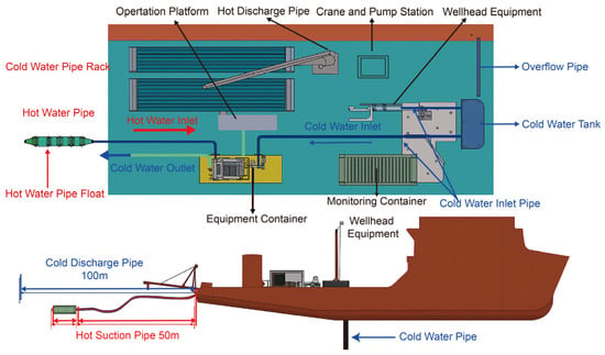
Following land-based commissioning, offshore trials were conducted to evaluate the integrated prototype under marine conditions. The test site was chosen based on prior oceanographic surveys that identified a stable thermocline, with deep-sea temperatures of approximately 5 °C at a depth of 900 m. The containerized power generation module was deployed aboard a research vessel equipped with a crane to lower the insulated cold-water pipe, which was assembled with modular quick-connect couplings. As illustrated in Figure 9, the test setup included a dedicated deck area for the containerized OTEC system, surface warm-water suction lines, and a remotely operated control system. The cold-water intake line was deployed through a pre-installed moon pool, allowing precise positioning and stable installation. This integrated arrangement enabled real-time monitoring and operation of all circulation, control, and data acquisition systems from the containerized control module, ensuring efficient and safe management of the open-sea trial. During the sea trial, the monitored cold-water temperature decreased to approximately 6.1 °C after about 20 min of circulation.
Figure 9.
Schematic of the open-sea deployment system for the containerized OTEC prototype.
5.3. Performance Evaluation and Analysis
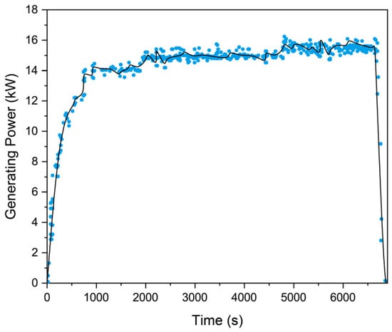
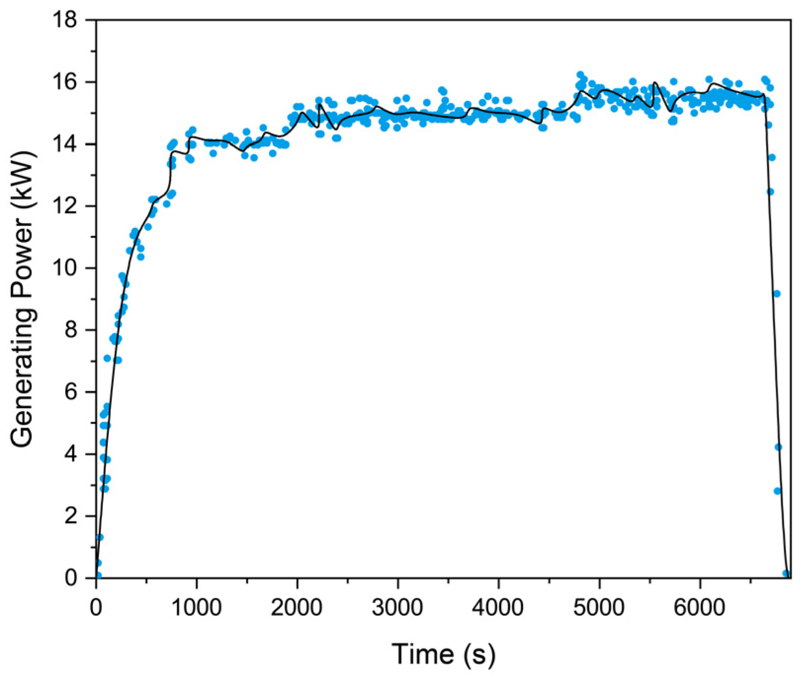
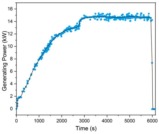
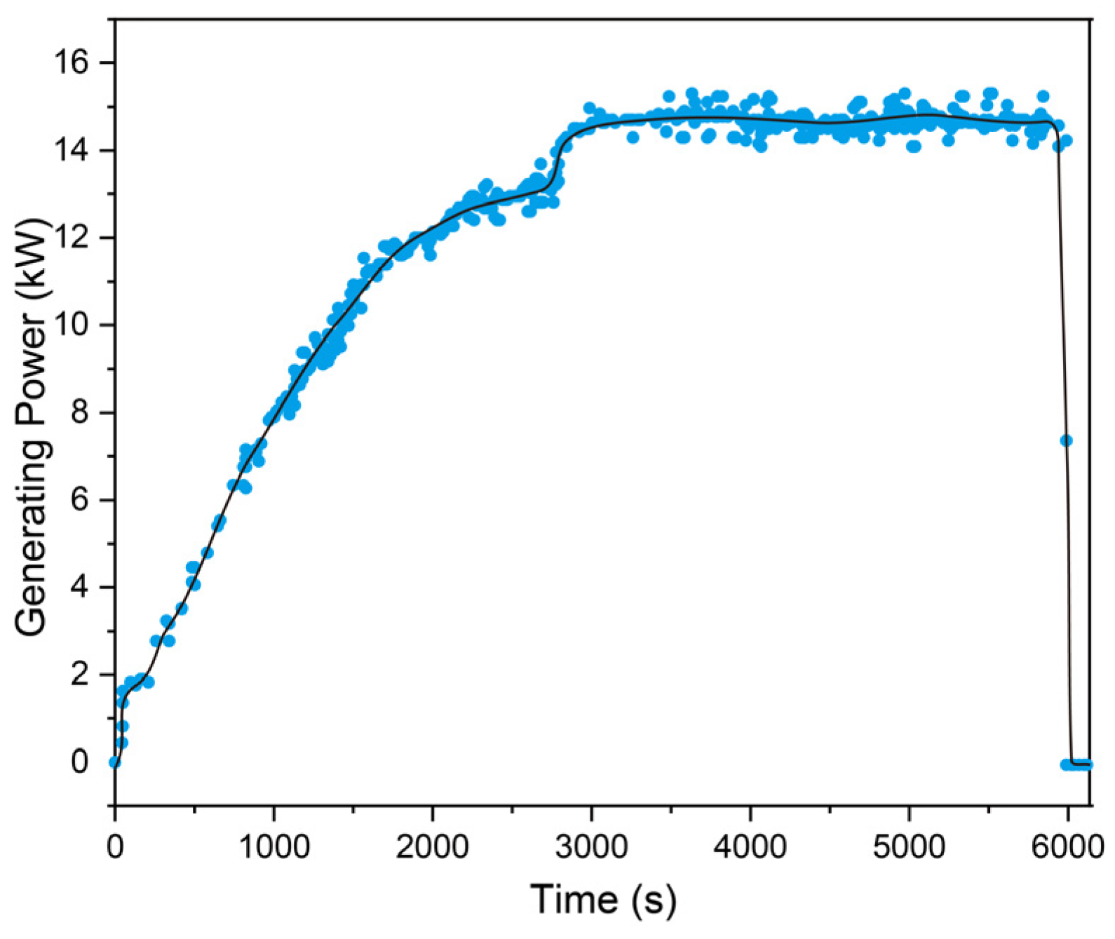
The land-based and offshore tests provided operating records of startup, power generation, and shutdown behavior. The cycle-efficiency values presented in Section 2 were obtained from thermodynamic design calculations rather than direct measurements during the sea trials. During offshore commissioning, a damaged liquid level sensor was identified, prompting recovery of approximately 600 kg of working fluid before restarting power generation trials. Following standard startup procedures, the working-fluid pump discharge rate was gradually increased, the bypass valve was closed, and the main valve was opened. During the first offshore run, the turbine reached 9700 rpm, and the maximum recorded electrical output was 16.4 kW. The run continued for nearly 2 h before a vibration alarm triggered shutdown (Figure 10).
Figure 10.
Measured electrical output during the first offshore power generation test. The system achieved a peak power of 16.4 kW at a turbine speed of 9700 rpm, sustaining operation for nearly two hours before being shut down by vibration alarms.
After inspection, the generator was restarted and stabilized at 8500 rpm with an electrical output of approximately 14 kW for an additional two hours, after which similar vibration alarms prompted a system shutdown (Figure 11). Preliminary diagnostics suggested turbine impeller bolt loosening or motor bearing wear as the likely cause. The offshore campaign accumulated 4 h and 47 min of power generation across separate runs.
Figure 11.
Measured electrical output during the second offshore power generation test. The turbine stabilized at 8500 rpm, delivering 14 kW of power for two hours before vibration alarms again prompted shutdown.
6. Engineering Discussion and Limitations
The present prototype employs a conventional closed Rankine cycle integrated within a containerized power-generation system. The focus of this work is therefore on system integration and offshore operation rather than on introducing a new thermodynamic cycle. Traditional OTEC plants rely on large-scale pumping of warm surface water and cold deep seawater through extensive pipeline networks, resulting in substantial parasitic energy consumption, increased system complexity, and environmental disturbances associated with nutrient upwelling and localized thermocline disruption. In the present prototype, the working fluid circulates in a closed Rankine loop, while warm surface seawater and cold deep seawater are separately circulated through the evaporator and condenser. Cold deep seawater is pumped through the insulated intake pipe to the container-mounted condenser.
The system’s modular and containerized integration further enhances its engineering practicality. The containerized prototype was installed aboard an existing research vessel for the offshore tests. The offshore trial also identified practical installation issues associated with the pipe couplings and supporting structures. Potential application scenarios include remote islands, offshore platforms, and marine research stations; however, the present study does not compare the system with conventional power-generation technologies in terms of cost or maintenance requirements.
Further design and testing are required to evaluate the performance of larger-capacity systems. In this context, the system aligns with the growing demand for distributed renewable energy solutions and offers a promising strategy to reduce reliance on fossil fuels in maritime operations.
Beyond its immediate application as a renewable power source, the system’s integration with marine infrastructure offers broader opportunities for innovation. By coupling energy harvesting with sensor networks, communications platforms, and oceanographic monitoring systems, the working-fluid circulation OTEC platform can serve as a multifunctional node for the marine Internet of Things (IoT). Future research will explore hybridization with other renewable sources such as wave and wind energy to create synergistic multi-source marine energy systems, leveraging the inherent stability of thermal gradients to balance intermittent resources.
The present study reports prototype operating results but does not establish economic or environmental advantages over other power-generation systems. The tests identified liquid-level and vibration-related interruptions that require further investigation before long-duration operation can be established.
7. Conclusions
This study developed and experimentally evaluated a 20 kW-class containerized Ocean Thermal Energy Conversion (OTEC) prototype based on a closed Rankine cycle using R134a as the working fluid. The working fluid circulates through the evaporator, radial-inflow turbine, condenser, and working-fluid pump, while warm surface seawater and pumped deep seawater provide the heat source and heat sink, respectively. The turbine–generator, brazed stainless-steel heat exchangers, circulation pumps, refrigerant components, and PLC-based control system were integrated into a containerized platform for land-based commissioning and offshore testing.
During the representative land-based commissioning tests, one run reached a peak electrical output of 11 kW, while another produced approximately 5 kW for about 11 min. Subsequent sea trials in the South China Sea recorded a maximum electrical output of 16.4 kW. The offshore campaign accumulated 4 h 47 min of power generation across separate runs. These electrical-output values should not be interpreted as full-system net power because the power required for deep-seawater lifting was not included in the reported power balance.
The tests also identified several engineering limitations. Cold-side temperature increases and refrigerant liquid-level variations affected the land-based runs, while the offshore tests encountered liquid-level sensor failure and vibration-triggered shutdowns of the turbine–generator system. These observations indicate that improved instrumentation, turbine–generator mechanical reliability, seawater-intake hardware, and operating control are required before long-duration operation can be established. Future work will therefore focus on resolving these issues, quantifying the complete system energy balance, and conducting longer-duration offshore tests under well-defined operating conditions.
Author Contributions
Conceptualization, F.X., B.N. and G.H.; methodology, J.L.; software, J.L.; validation, J.L., Y.W. and F.O.; formal analysis, Y.W., Q.S. and B.N.; investigation, J.L., Y.W., Y.L. and B.N.; resources, F.O., B.N. and G.H.; data curation, Y.L.; writing—original draft preparation, J.L.; writing—review and editing, F.X. and G.H.; visualization, J.L.; supervision, Q.S. and G.H.; project administration, G.H.; funding acquisition, F.X. and G.H. All authors have read and agreed to the published version of the manuscript.
Funding
This research was funded by the Nansha District Science and Technology Plan Project, grant number 2024ZD008; the National Natural Science Foundation of China, grant number 52305135; and the Guangdong Provincial Project, grant number 2023QN10L545.
Data Availability Statement
The raw data supporting the conclusions of this article will be made available by the authors on request.
Acknowledgments
During the preparation of this manuscript/study, the author(s) used ChatGPT 5.5 for the purpose of text polishing. The authors have reviewed and edited the output and take full responsibility for the content of this publication.
Conflicts of Interest
The authors declare no conflicts of interest.
References
- Kumar, V.; Shrivastava, R.; Untawale, S. Solar energy: Review of potential green & clean energy for coastal and offshore applications. Aquat. Procedia 2015, 4, 473–480. [Google Scholar] [CrossRef] [Scilit]
- Wen, Y.; Lin, P. Exploitation potential of tidal current energy in Southern China seas. Energy Convers. Manag. 2022, 267, 115901. [Google Scholar] [CrossRef] [Scilit]
- Li, G.; Zhu, W. Tidal current energy harvesting technologies: A review of current status and life cycle assessment. Renew. Sustain. Energy Rev. 2023, 179, 113269. [Google Scholar] [CrossRef] [Scilit]
- Wang, Y.; Du, H.; Yang, H.; Xi, Z.; Zhao, C.; Qian, Z.; Chuai, X.; Peng, X.; Yu, H.; Zhang, Y. A rolling-mode triboelectric nanogenerator with multi-tunnel grating electrodes and opposite-charge-enhancement for wave energy harvesting. Nat. Commun. 2024, 15, 6834. [Google Scholar] [CrossRef] [Scilit] [PubMed]
- Xi, Z.; Du, H.; Wang, Y.; Yu, H.; Dai, S.; Fan, M.; Liu, J.; Su, Q.; Wang, H.; Hu, G. A ternary-dielectric rolling TENG array for robust ocean energy harvesting and distributed environmental monitoring. Nano Energy 2025, 143, 111318. [Google Scholar] [CrossRef] [Scilit]
- Li, M.; Luo, H.; Zhou, S.; Kumar, G.M.S.; Guo, X.; Law, T.C.; Cao, S. State-of-the-art review of the flexibility and feasibility of emerging offshore and coastal ocean energy technologies in East and Southeast Asia. Renew. Sustain. Energy Rev. 2022, 162, 112404. [Google Scholar] [CrossRef] [Scilit]
- Wang, Y.; Liu, X.; Chen, T.; Wang, H.; Zhu, C.; Yu, H.; Song, L.; Pan, X.; Mi, J.; Lee, C. An underwater flag-like triboelectric nanogenerator for harvesting ocean current energy under extremely low velocity condition. Nano Energy 2021, 90, 106503. [Google Scholar] [CrossRef] [Scilit]
- Herrera, J.; Sierra, S.; Ibeas, A. Ocean thermal energy conversion and other uses of deep sea water: A review. J. Mar. Sci. Eng. 2021, 9, 356. [Google Scholar] [CrossRef] [Scilit]
- Khan, M.Z.A.; Khan, H.A.; Aziz, M. Harvesting energy from ocean: Technologies and perspectives. Energies 2022, 15, 3456. [Google Scholar] [CrossRef] [Scilit]
- Nihous, G.C. A preliminary assessment of ocean thermal energy conversion resources. J. Energy Resour. Technol. 2007, 129, 10–17. [Google Scholar] [CrossRef] [Scilit]
- Nihous, G.C. An order-of-magnitude estimate of ocean thermal energy conversion resources. J. Energy Resour. Technol. Trans. ASME 2005, 127, 328–333. [Google Scholar] [CrossRef] [Scilit]
- Abbas, S.M.; Alhassany, H.D.S.; Vera, D.; Jurado, F. Review of enhancement for ocean thermal energy conversion system. J. Ocean Eng. Sci. 2023, 8, 533–545. [Google Scholar] [CrossRef] [Scilit]
- Langer, J.; Cahyaningwidi, A.A.; Chalkiadakis, C.; Quist, J.; Hoes, O.; Blok, K. Plant siting and economic potential of ocean thermal energy conversion in Indonesia a novel GIS-based methodology. Energy 2021, 224, 120121. [Google Scholar] [CrossRef] [Scilit]
- Langer, J.; Quist, J.; Blok, K. Recent progress in the economics of ocean thermal energy conversion: Critical review and research agenda. Renew. Sustain. Energy Rev. 2020, 130, 109960. [Google Scholar] [CrossRef] [Scilit]
- Takahashi, P.K.; Trenka, A. Ocean thermal energy conversion: Its promise as a total resource system. Energy 1992, 17, 657–668. [Google Scholar] [CrossRef] [Scilit]
- Ravindran, M.; Abraham, R. The Indian 1 MW demonstration OTEC plant and the development activities. In Proceedings of the OCEANS’02 MTS/IEEE, Biloxi, MS, USA, 29–31 October 2002; pp. 1622–1628. [Google Scholar]
- Xiao, C.; Gulfam, R. Opinion on ocean thermal energy conversion (OTEC). Front. Energy Res. 2023, 11, 1115695. [Google Scholar] [CrossRef] [Scilit]
- Lu, B.; Liu, Y.; Zhai, X.; Zhang, L.; Chen, Y. Design and experimental study of 50 kW Ocean Thermal energy conversion test platform based on organic rankine cycle. J. Mar. Sci. Eng. 2024, 12, 463. [Google Scholar] [CrossRef] [Scilit]
- Srinivasan, N. A new improved ocean thermal energy conversion system with suitable floating vessel design. In Proceedings of the International Conference on Offshore Mechanics and Arctic Engineering, Honolulu, HI, USA, 31 May–5 June 2009; pp. 1119–1129. [Google Scholar]
- Ma, Q.; He, G.; Li, J.; Wu, Z.; Lu, H.; Wang, C.; Wang, S. Innovative Design and Performance Evaluation of a Compact 1 MW Radial Inflow Turbine with Non-Azeotropic Fluids for Ocean Thermal Energy Conversion Applications. Energy 2025, 335, 138105. [Google Scholar] [CrossRef] [Scilit]
- Wang, M.; Jing, R.; Zhang, H.; Meng, C.; Li, N.; Zhao, Y. An innovative Organic Rankine Cycle (ORC) based Ocean Thermal Energy Conversion (OTEC) system with performance simulation and multi-objective optimization. Appl. Therm. Eng. 2018, 145, 743–754. [Google Scholar] [CrossRef] [Scilit]
- Rajagopalan, K.; Nihous, G.C. Estimates of global Ocean Thermal Energy Conversion (OTEC) resources using an ocean general circulation model. Renew. Energy 2013, 50, 532–540. [Google Scholar] [CrossRef] [Scilit]
- Calvo, M.S.; Lee, H.S. Ocean thermal energy conversion (OTEC) potential in central American and Caribbean regions: A multicriteria analysis for optimal sites. Appl. Energy 2025, 394, 126182. [Google Scholar] [CrossRef] [Scilit]
- Vega, L.A. Ocean thermal energy conversion primer. Mar. Technol. Soc. J. 2002, 36, 25–35. [Google Scholar] [CrossRef] [Scilit]
- Nakib, T.H.; Hasanuzzaman, M.; Rahim, N.; Habib, M.A.; Adzman, N.N.; Amin, N. Global challenges of ocean thermal energy conversion and its prospects: A review. J. Ocean Eng. Mar. Energy 2025, 11, 197–231. [Google Scholar] [CrossRef] [Scilit]
- Chen, W.; Huo, E. Opportunities and challenges of ocean thermal energy conversion technology. Front. Energy Res. 2023, 11, 1207062. [Google Scholar] [CrossRef] [Scilit]
- Wang, G.; Yang, Y.; Wang, S.; Zhang, H.; Wang, Y. Efficiency analysis and experimental validation of the ocean thermal energy conversion with phase change material for underwater vehicle. Appl. Energy 2019, 248, 475–488. [Google Scholar] [CrossRef] [Scilit]
- Zhang, Z.; Yuan, H.; Yi, S.; Sun, Y.; Peng, W.; Mei, N. Theoretical analysis on temperature-lifting cycle for ocean thermal energy conversion. Energy Convers. Manag. 2024, 300, 117946. [Google Scholar] [CrossRef] [Scilit]
- Vera, D.; Baccioli, A.; Jurado, F.; Desideri, U. Modeling and optimization of an ocean thermal energy conversion system for remote islands electrification. Renew. Energy 2020, 162, 1399–1414. [Google Scholar] [CrossRef] [Scilit]
- Zereshkian, S.; Mansoury, D. A study on the feasibility of using solar radiation energy and ocean thermal energy conversion to supply electricity for offshore oil and gas fields in the Caspian Sea. Renew. Energy 2021, 163, 66–77. [Google Scholar] [CrossRef] [Scilit]
- Adiputra, R.; Utsunomiya, T.; Koto, J.; Yasunaga, T.; Ikegami, Y. Preliminary design of a 100 MW-net ocean thermal energy conversion (OTEC) power plant study case: Mentawai island, Indonesia. J. Mar. Sci. Technol. 2020, 25, 48–68. [Google Scholar] [CrossRef] [Scilit]
- Ou, F.; Ning, B.; Li, J.; Tian, Y.; Qiu, D.; Geng, L.; Jin, X. Design, construction and sea trials of the 20kW ocean thermal energy conversion in the South China Sea. Energy 2025, 342, 139641. [Google Scholar] [CrossRef] [Scilit]
- Sun, F.; Ikegami, Y.; Jia, B.; Arima, H. Optimization design and exergy analysis of organic rankine cycle in ocean thermal energy conversion. Appl. Ocean Res. 2012, 35, 38–46. [Google Scholar] [CrossRef] [Scilit]
- Chen, F.; Liu, L.; Peng, J.; Ge, Y.; Wu, H.; Liu, W. Theoretical and experimental research on the thermal performance of ocean thermal energy conversion system using the rankine cycle mode. Energy 2019, 183, 497–503. [Google Scholar] [CrossRef] [Scilit]
- Ikegami, Y.; Yasunaga, T.; Morisaki, T. Ocean thermal energy conversion using double-stage Rankine cycle. J. Mar. Sci. Eng. 2018, 6, 21. [Google Scholar] [CrossRef] [Scilit]
- Fan, C.; Zhang, C.; Chen, Y. Dynamic operation characteristics of ocean thermal energy conversion using Kalina cycle. Renew. Energy 2024, 231, 120909. [Google Scholar] [CrossRef] [Scilit]
- Koto, J. Potential of ocean thermal energy conversion in Indonesia. Int. J. Environ. Res. Clean Energy 2016, 4, 1–7. [Google Scholar] [CrossRef] [Scilit]

Disclaimer/Publisher’s Note: The statements, opinions and data contained in all publications are solely those of the individual author(s) and contributor(s) and not of MDPI and/or the editor(s). MDPI and/or the editor(s) disclaim responsibility for any injury to people or property resulting from any ideas, methods, instructions or products referred to in the content. |
© 2026 by the authors. Licensee MDPI, Basel, Switzerland. This article is an open access article distributed under the terms and conditions of the Creative Commons Attribution (CC BY) license.