


Abstract
To address the high cost, structural complexity, and poor horizontal transplanting performance of existing sweet potato seedling transplanting mechanisms, this study proposes a Fourier series-based kinematic synthesis method and designs a non-circular gear planetary transplanting mechanism, which is then validated through virtual simulation and prototype testing. Based on the agronomic requirements for horizontal transplanting, key positions including seedling pick-up, soil entry, and soil exit are identified. The complex vector method is applied to establish a 2R open-chain kinematic synthesis model with trajectory and posture error equations, from which the optimal mechanism parameters are derived. Kinematic modeling of the non-circular gear planetary train is conducted, and auxiliary design software is developed to generate the pitch curves of the non-circular gears. A cylindrical cam mechanism is designed for seedling gripping and release. Structural design and virtual prototyping are completed, and simulations verify the theoretical model. A physical prototype is manufactured for kinematic and field testing. The results demonstrate high consistency among the measured, simulated, and theoretical trajectories, with a maximum deviation of 0.6° (relative error of 0.83%) at the key posture positions. At rotational speeds of the transplanting mechanism of 30 r/min and 40 r/min, the average transplanting success rates reach 91.2% and 81.2%, respectively, while the planting depth, horizontal underground length, and plant spacing all satisfy the agronomic requirements, confirming the feasibility of the proposed design. This study provides a theoretical and technical foundation for the development of a high-performance sweet potato seedling transplanting mechanism.
1. Introduction
Sweet potato is an important food and economic crop in China, with an annual planting area of approximately 1 million hectares [1]. The labor demand of the sweet potato seedling transplanting stage accounts for approximately 30% of the total labor input in the entire production process [2,3]. Therefore, researching sweet potato seedling transplanting mechanisms is of great practical significance for improving the mechanization level of sweet potato cultivation and promoting the sustainable development of the sweet potato industry [4,5].
Currently, the slender and soft nature of sweet potato seedlings makes mechanized orderly separation difficult, so semi-automatic transplanters with manual feeding are predominantly used worldwide. In Europe and the United States, large-scale transplanters [2,4]—such as the semi-automatic chain-clamp transplanter from Marcinick (USA) [6] and the Fox Drive finger-type transplanter from Checchi & Magli (Italy) [7]—achieve high efficiency but have complex structures [5], high costs, and mainly adopt oblique planting, making them difficult to promote in China [2]. In Japan, where planting areas are mostly hilly and mountainous, small-scale transplanters are used. For instance, Kubota’s transplanter [8,9] and Iseki’s PVH103 [8,10] can achieve oblique or boat-bottom-shaped planting, but these machines also face high costs and are difficult to promote in China [9,10,11].
In contrast, research on sweet potato seedling transplanters in China is still at the prototype testing stage, without practical application. For oblique planting, Zhu et al. [5] developed a belt-clip bare-root seedling transplanter using an incomplete gear and four-bar linkage, which, however, suffered from structural complexity and poor operational stability. Although the bionic finger-clip mechanism designed by Shentu et al. [12] successfully applied the crank–rocker principle, its linkages were prone to severe wear, vibration, and asynchronous motion. Liu et al. [13] coupled a sliding table with a rotary unit to generate both oblique and transverse horizontal trajectories, yet this configuration yielded low transplanting efficiency and high manufacturing costs. Similarly, the combination of a crank–rocker mechanism and a cam-driven finger clip proposed by Li et al. [14] for boat-bottom-shaped planting remains inapplicable to horizontal transplanting. To enable side-insertion horizontal transplanting, Zhang et al. [15] integrated a crank–rocker with a cam structure, though the overall system exhibited excessive complexity. In contrast, Zhou et al. [16] successfully achieved horizontal transplanting by designing a specialized seedling mechanism driven by an elliptical gear planetary train. Building upon this, Ye et al. [17] further proposed a sweet potato seedling transplanting mechanism driven by a deformed elliptical gear planetary train. Although planetary gear transmission offers advantages such as a compact structure and wide transmission ratio range [18], existing transplanting mechanisms based on elliptical or deformed elliptical gear planetary trains [16,17] rely mainly on traditional geometric methods for trajectory synthesis, which are essentially limited to single-point approximation and involve a relatively complex structure. Furthermore, their design freedom is significantly constrained by the fixed pitch curve equations of elliptical and deformed elliptical gears. By contrast, Fourier series can accurately describe complex periodic motions with a small number of harmonic parameters, providing an effective tool for simultaneous and precise global control of the key target poses.
To address these limitations, this paper proposes a Fourier series-based kinematic synthesis method for sweet potato seedling transplanting mechanisms and designs a non-circular gear planetary train transplanting mechanism. The proposed method enables simultaneous and precise control of multiple key poses and offers greater design freedom through non-circular gears. Specifically, a global scheme and key poses are first determined according to the horizontal transplanting agronomic requirements. A motion synthesis mathematical model of a 2R open-chain mechanism is then established based on the Fourier series to solve for the optimal parameters. Furthermore, kinematic modeling is performed, followed by the design of non-circular gear pitch curves and the cylindrical cam mechanism. Finally, simulations and prototype experiments verify the mechanical design, kinematic characteristics, and operational performance, providing a solid foundation for the development of sweet potato seedling transplanters.
2. Materials and Methods
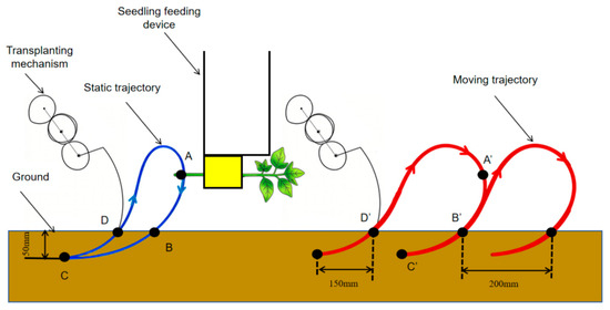
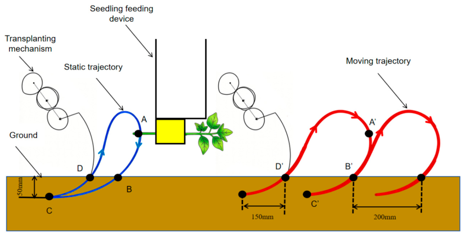
The horizontal transplanting method for sweet potato seedlings is a widely adopted cultivation practice. Compared with other planting methods such as oblique and vertical transplanting, this approach not only promotes a higher yield of stems and vines but also ensures uniform tuber size, thereby facilitating high-yield harvesting and delivering greater economic returns [17,19]. As illustrated in Figure 1, horizontal transplanting is suitable for sweet potato seedlings with a length of 200–300 mm. The planting depth H is approximately 50 mm, the horizontal length of the underground seedling L is around 150–200 mm, and the plant spacing S is approximately 200 mm. Given the soft and slender nature of sweet potato stalks, automated orderly seedling separation is difficult to achieve; therefore, a semi-automatic sweet potato seedling transplanting scheme is adopted in this study. During operation, the seedlings are manually fed into an intermittent feeding device and orderly conveyed to the seedling pick-up position, where they are subsequently gripped by the transplanting mechanism and planted into the soil along a predetermined trajectory. The transplanting mechanism comprises a non-circular gear planetary train and a transplanting arm, whose tip trajectory must precisely conform to the agronomic requirements of horizontal transplanting. To this end, the static trajectory of the mechanism is divided into three distinct phases [16]: (1) Seedling pick-up and conveying phase AB: At the pick-up point A, the transplanting arm is oriented nearly perpendicular (≈90°) to the seedling stalk axis to ensure reliable perpendicular gripping. At the soil-entry point B, the angle between the transplanting arm and the horizontal plane ranges from 40° to 45° to reduce soil penetration resistance. (2) Planting phase BC: At the planting point C, the transplanting arm is oriented approximately horizontally, ensuring steady seedling release and precise soil placement. Within the absolute trajectory corresponding to this phase, the planting depth is approximately 50 mm, the horizontal distance is about 150–200 mm, and the plant spacing is roughly 200 mm. (3) Return phase CD: The transplanting arm returns to its initial position via the soil-exit point D, preparing for the next operational cycle.
Figure 1.
Schematic of the horizontal sweet potato seedling transplanting scheme and key positions.
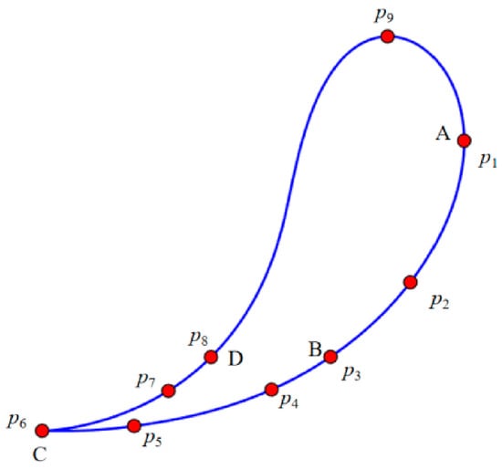
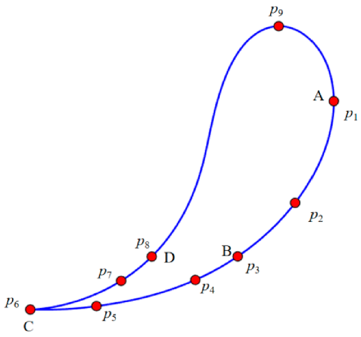
As shown in Figure 2, nine specific positions including the aforementioned key points are selected along the trajectory of the transplanting mechanism, and their corresponding pose data are determined (as listed in Table 1) to provide a solid basis for the subsequent mechanism synthesis. Specifically, pose point P1 controls the seedling pick-up position, while soil-entry point P3 and planting point P6 regulate the underground seedling length L. Soil-entry point P3 and soil-exit point P8 govern the entry and exit locations and orientations, ensuring that the orientation of the gripping claw is nearly tangent to the path during soil entry and exit, thereby minimizing the soil resistance encountered by the claw tip within the ridge. Furthermore, auxiliary pose points P4, P5, and P7 help ensure close alignment between the soil-entry and soil-exit trajectories, while pose points P2 and P9 regulate the conveying path trajectory and the peak height of the return phase, respectively.
Figure 2.
Distribution of specific position points along the trajectory.
Table 1.
Specific positions and corresponding posture angle data of the mechanism trajectory.
2.1. Working Principle of the Transplanting Mechanism
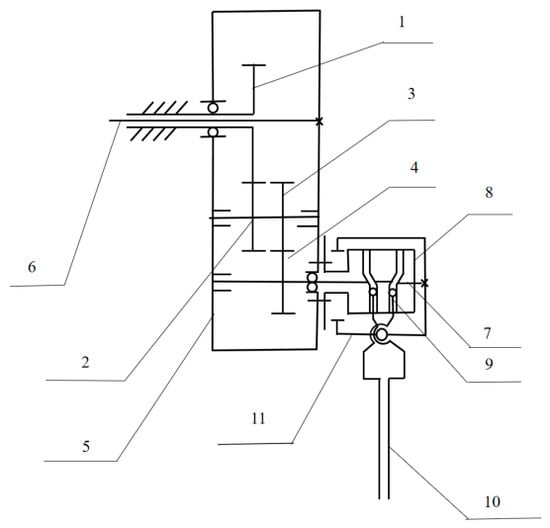
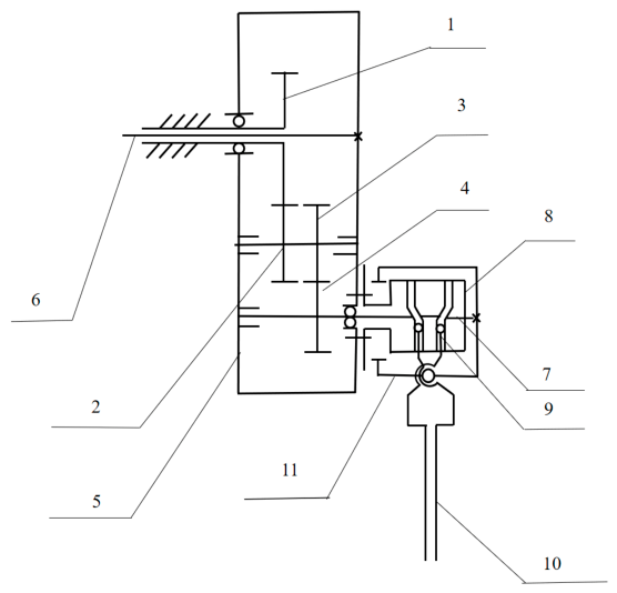
As illustrated in Figure 3, the sweet potato seedling transplanting mechanism driven by a non-circular gear planetary train consists of two primary components: the planetary gear train transmission mechanism and the transplanting arm. The transmission mechanism employs a two-stage non-circular gear train: sun gear 1 and the first intermediate gear 2 constitute the first-stage transmission, while the second intermediate gear 3 and planet gear 4 form the second-stage transmission, with sun gear 1 fixed to the frame. During operation, the drive shaft 6 drives the rigidly connected planet carrier 5 to rotate clockwise at a uniform speed. Driven by the two-stage non-circular gear transmission, planet gear 4 rotates counterclockwise around its own axis at a non-uniform speed. Consequently, the motion of planet gear 4 is a compound movement combined by the uniform clockwise rotation with the planet carrier 5 and the non-uniform counterclockwise rotation around its own axis. Since the housing of the transplanting arm is rigidly connected to the planet gear shaft, the trajectory of the arm tip can be optimized through mechanism design to strictly satisfy the horizontal transplanting requirements of sweet potato seedlings. The transplanting arm utilizes a cylindrical cam mechanism to perform the seedling pick-up and release operations. Cylindrical cam 8 is rigidly attached to the planet carrier 5; as planet gear 4 drives the cam box housing 11 and the gripping claw 10 fixed on it to rotate counterclockwise via the drive shaft 7, the roller 9 tracks along the profile of the cylindrical cam 8. The gripping claw 10 closes when the roller 9 resides on the inner dwell segment (near dwell) of the cam and opens when it reaches the outer dwell segment (far dwell). This achieves precise sequential control characterized by “closing and gripping at the pick-up point, maintaining during the conveying phase, opening and releasing at the planting point, and returning empty during the return phase,” thereby cooperatively completing a full transplanting cycle. The proposed transplanting mechanism employs only 11 major moving elements. Compared with conventional crank–rocker and cam mechanisms, this compact design with fewer parts reduces the accumulation of assembly errors, improves transmission reliability, and subsequently lowers manufacturing costs.
Figure 3.
Schematic diagram of the planetary gear train sweet potato seedling transplanting mechanism. 1. Sun gear; 2. First intermediate gear; 3. Second intermediate gear; 4. Planet gear; 5. Planet carrier; 6. Power shaft; 7. Transmission shaft; 8. Cylindrical cam; 9. Roller; 10. Gripping claw; 11. Transplanting arm housing.
2.2. Establishment and Solution of the Transplanting Mechanism Synthesis Model
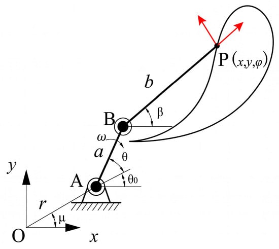
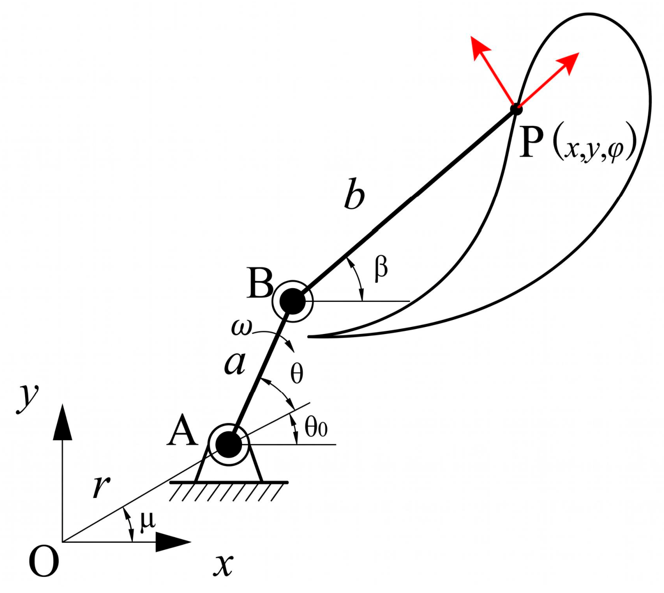
As illustrated in Figure 4, to establish the kinematic synthesis model of the sweet potato seedling transplanting mechanism driven by a non-circular gear planetary train, the mechanism is equivalent to a planar 2R open-chain mechanism [20,21,22]. Taking point O as the origin of the coordinate system, the length of the base link OA is defined as r, and its angle with the x-axis is designated as . The input link AB (with a length of a) represents the planet carrier of the transplanting mechanism, with its center of rotation located at point A; ω denotes its angular velocity, and its rotation angle is jointly determined by the initial phase angle 0 and the dynamic input angle . The output link BP (with a length of b) represents the transplanting arm, with its center of rotation at point B and its output angle denoted as . The posture angle of the transplanting arm is defined as the rotation angle between the output link BP and the trajectory guide line, and point P serves as the trajectory generation point at the arm tip.
Figure 4.
Schematic diagram of the planar 2R open-chain mechanism.
The arm tip trajectory P(x,y,) of the planar 2R open-chain mechanism where represents the posture angle at point P, is a function of the input angle with a period of 2π. According to the Fourier series theory [23,24], it can be expressed in the form of a complex series as follows:
where denotes the Fourier coefficient, whose value establishes a definite mathematical mapping relationship with the mechanism parameters r, , a, b, and .
Based on the complex vector analysis method [25], the closed-loop vector equation is constructed as follows:
By expressing Equation (2) in complex form, it is multiplied by its complex conjugate and rearranged to yield Equation (3):
Let ; ; ; ; ; . The Fourier series expansions of and are given by:
The Fourier series expansion of the output angle β is expressed as:
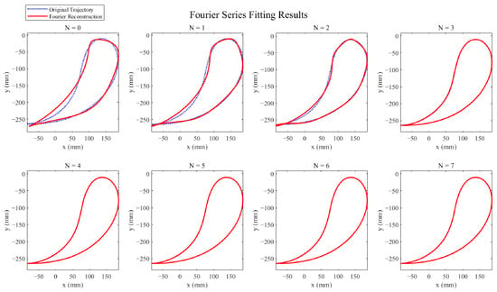
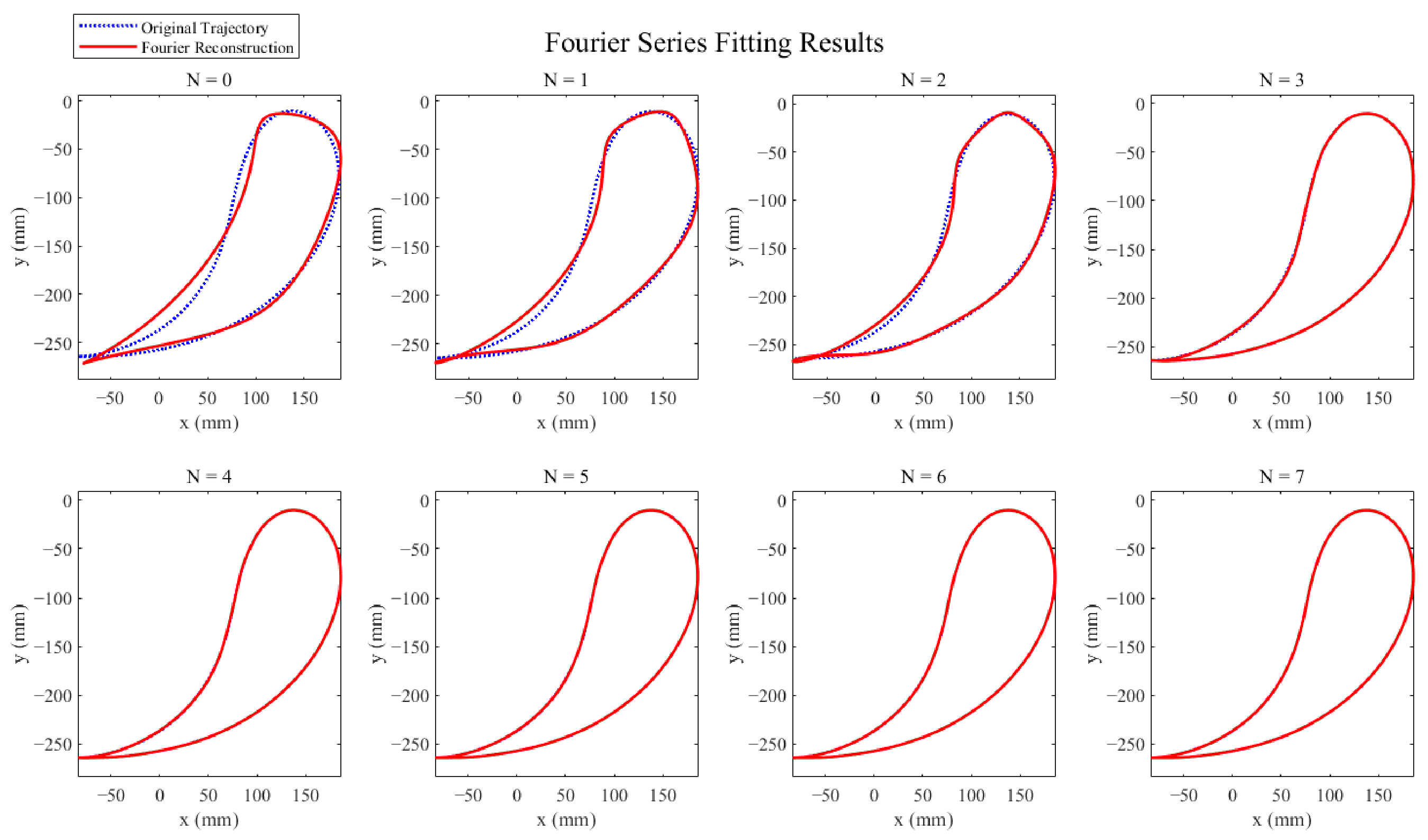
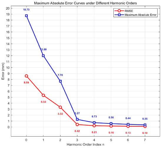
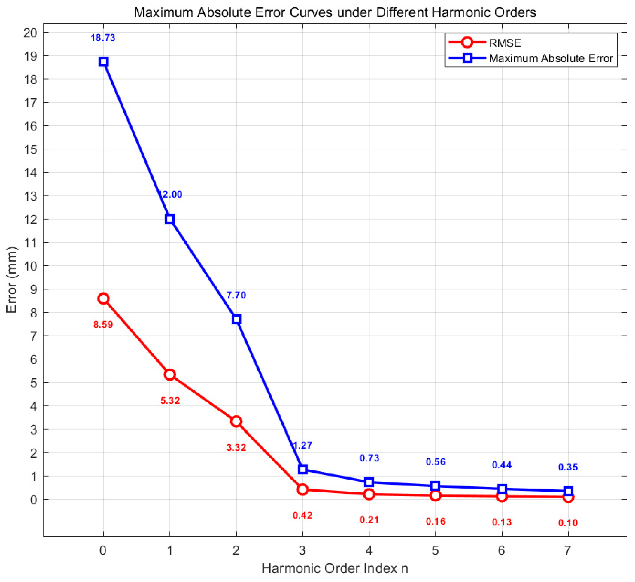
To obtain the continuous target trajectory for Fourier fitting, the nine key poses listed in Table 1 were first interpolated using a cubic B-spline to construct a continuous and smooth target curve. Furthermore, Fourier fitting and error analysis were performed for different harmonic orders n, and the results are shown in Figure 5 and Figure 6. The fitting results in Figure 5 indicate that when n < 3, a significant deviation exists between the fitted curve and the target trajectory; when n = 3, the global characteristics of the trajectory can be reproduced with high precision. The quantitative error analysis in Figure 6 further demonstrates that both the root mean square error (RMSE) and the maximum absolute error exhibit a decreasing trend as n increases. The RMSE drops below 0.5 mm after n = 3 and remains essentially stable thereafter. Therefore, considering both computational efficiency and fitting accuracy, the harmonic order n is ultimately determined to be 3.
Figure 5.
Fourier series fitting results of the mechanism arm tip trajectory.
Figure 6.
Maximum absolute error curves under different harmonic orders n.
Substituting the expanded terms , , , and into Equation (3) yields:
where:
The terms , , and (n = −3, −2, …, 2, 3) represent the Fourier series harmonic parameters of the trajectory and posture of the linkage mechanism arm tip. These parameters are calculated from the continuous target trajectory using the discrete Fourier transform (DFT), with the results listed in Table 2.
Table 2.
Harmonic parameters of the 2R open-chain linkage mechanism motion output.
By analyzing Equation (6), it can be found that G−3, G−2, G−1, G0, G1, G2, G3 are the complete coefficient expressions. That is, these coefficient expressions remain unchanged when the harmonic parameters are taken at higher orders. According to the properties of complex exponential functions (i.e., the linear independence of Fourier basis functions), their values must be zero. Thus, the following scalar equations are obtained:
Although the scalar equations Gk = 0 eliminate the Fourier basis functions, to further reduce the dimensionality of the solution, the following intermediate variables are introduced:
Substituting the above replacements into the five scalar equations Gk = 0 and eliminating the original variables p1, p−1, p2, p−2, b and their higher-order terms, after combining like terms and rearranging, the original complex 15-variable system is compressed into four polynomial equations containing only X, Y, U, V
For ease of presentation, the four independent equations in Equation (11) are relabeled as R, N, P, Q, respectively:
Among the equations R = 0, N = 0, P = 0, Q = 0, both R = 0 and Q = 0 are linear in U and V, with coefficients determined solely by the known harmonic parameters cn and bn. Thus, R = 0 and Q = 0 can be rearranged as:
where A1 = , B1 = , A4 = , B4 = , and C1, C4 are known functions of X and Y. By Cramer’s rule, U and V can be solved as:
Unlike R and Q, the equations N = 0 and P = 0 contain cross-product terms and . Substituting the solved U and V into N = 0 and P = 0 eliminates R and V, yielding two quadratic equations containing only X and Y:
where Ai, Bi, and Ci are known functions of X and Y. Applying the conjugate constraint gives:
Eliminating from Equation (16) using the resultant method theoretically yields a univariate quartic equation with respect to X, as shown in Equation (17):
The univariate quartic equation in Equation (17) was numerically solved using Mathcad Prime 9.0 software to obtain the intermediate variable X. The conjugate variable Y was determined by the constraint . Subsequently, X and Y were substituted into the linear equations in Equation (13) to solve for the intermediate variables U and V. Based on the definitions in Equation (10), the original variables p1, p−1, p2, p−2 and b were determined. Finally, the design variables r, μ, a, b, and θ0 were calculated using Equation (18).
After performing the aforementioned solution, a total of four sets of 2R mechanism parameters satisfying the constraints are obtained, as listed in Table 3. To evaluate the synthesis accuracy of each parameter set and select the optimal solution, the following calculation formulas for the comprehensive pose synthesis error are established:
where the coordinate transformation formula for the comprehensive pose points is given by:
where M is the number of selected specific position points; (pix, piy) represents the coordinates of the i-th specific position point, and (pidx, pidy) represents the coordinates of the i-th specific position point generated by mechanism synthesis; (pix0, piy0, i) denotes the pose coordinates of the i-th specific position point, and (pidx0, pidy0, di) denotes the coordinates of the i-th specific position point generated by mechanism synthesis. The auxiliary point B is defined by translating the end point P along the posture direction by a characteristic length g. Its position error is equivalent to the vector sum of the position error and the posture-angle error. (where denotes the posture angle difference). This method prevents the computational discontinuity caused by the 360° periodicity of angle differences. With g = 1, the posture-angle error (rad) is mapped into an equivalent distance error (mm), ensuring dimensional consistency between TE1 (trajectory synthesis error) and TE2 (pose synthesis error).
Table 3.
Parameters of the 2R open-chain linkage mechanism.
As shown in Table 3, among the four candidate schemes, Scheme 1 exhibits the smallest trajectory error (TE1) and pose error (TE2), indicating the highest comprehensive synthesis accuracy. Therefore, the parameters of Scheme 1 are selected as the optimal solution for the subsequent non-circular gear planetary train design.
2.3. Non-Circular Gear Planetary Train Design
2.3.1. Calculation and Analysis of Transmission Ratios
To achieve the kinematic mapping relationship between the input link angle θ and the output link angle β of the 2R open-chain mechanism with parameters r = 4.51 mm, a = 86.16 mm and b = 190.97 mm, a non-circular gear planetary train transmission mechanism is designed in this study. The movement of the planet carrier replaces the motion of the 2R open-chain mechanism’s input link [23,26,27] and the planet gear replicates the motion of the output link through the planetary gear transmission, thereby reproducing the exact kinematic function relationship.
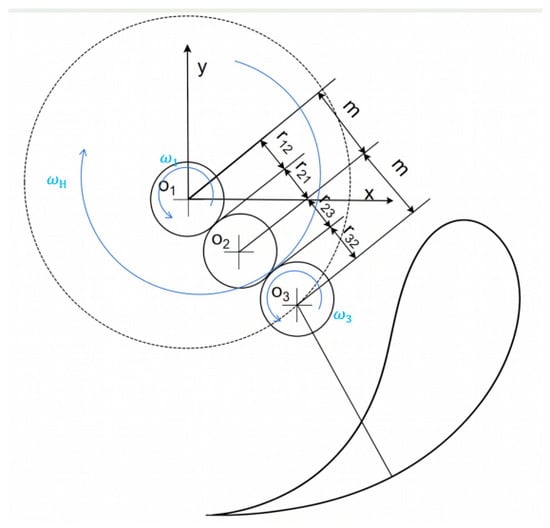
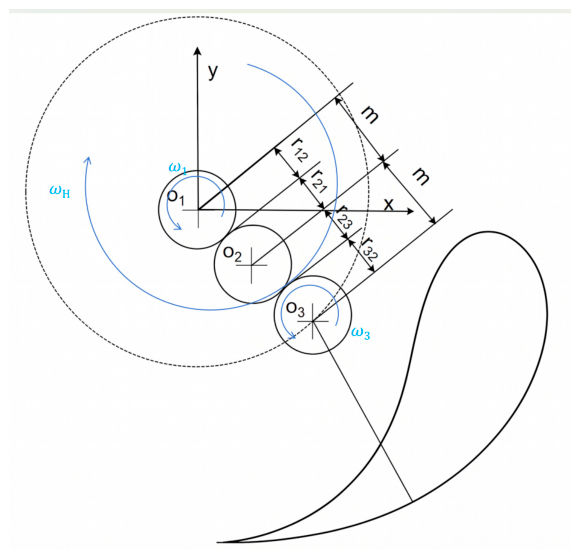
As illustrated in Figure 7, the aforementioned planetary gear train is converted into a fixed-axis gear train by using the inversion method of epicyclic gear trains, and its transmission ratio is derived based on the relative angular velocity relationships among the components.
Figure 7.
Kinematic diagram of the non-circular gear planetary train mechanism.
The total transmission ratio between the sun gear and the planet gear, , is calculated as follows:
where denotes the total transmission ratio between the planet gear and the sun gear; represents the rotation angle of the planet gear relative to the planet carrier, and is the rotation angle of the planet carrier; is the angular velocity of the sun gear, which equals 0; is the angular velocity of the planet carrier; and is the angular velocity of the planet gear.
The discrete data of the relative rotation angle of the planetary gear train are extracted and smoothed using a cubic B-spline curve. To balance the load distribution of the two-stage non-circular gears, the fundamental sub-transmission ratios of the first and second stages, i21 and i23, are initially obtained based on the equal distribution principle:
To ensure that the pitch curves of the non-circular gears are perfectly closed within a kinematic cycle, a correction coefficient k must be introduced:
By applying the correction coefficients to the two transmission stages respectively, the final sub-transmission ratios are yielded as:
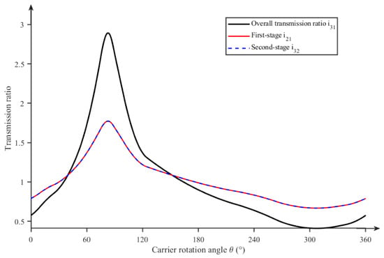
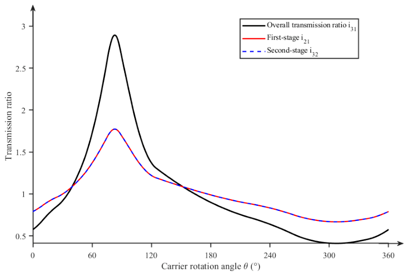
The total transmission ratio curve and the allocated two-stage sub-transmission ratio curves are shown in Figure 8 below.
Figure 8.
Total transmission ratio and two-stage sub-transmission ratio curves of the planetary gear train.
2.3.2. Pitch Curves of Non-Circular Gears and Kinematic Trajectory Equations
The relationship between the center distance m of the two-stage non-circular gear transmission and the length of the planet carrier a is expressed as follows:
According to the gear meshing principle, the linear velocities of non-circular gears at any meshing point are identical. Thus, the polar radius equations of the pitch curves for each gear stage are derived as follows [26]:
where r12, r21, r23 and r32 denote the pitch curve polar radii of the sun gear, the first intermediate gear, the second intermediate gear, and the planet gear, respectively, and m represents the center distance.
The coordinate equations of the non-circular gear pitch curves in the Cartesian coordinate system [27,28,29] are given by:
In the non-circular gear planetary train, the transplanting arm of the mechanism is rigidly connected to the planet gear shaft. The displacement equation of the arm tip point P [29] is derived as follows:
By taking the derivative of Equation (28), the velocity equation of the arm tip point P is obtained as:
Considering the forward speed of the transplanter, the dynamic trajectory coordinate equation of the arm tip point P is formulated as follows:
where v represents the forward speed of the transplanter (in mm/s), and represents the angular velocity of the planet carrier (in rad/s), with n denoting the rotational speed of the planet carrier (in r/min).
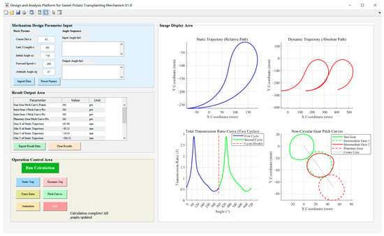
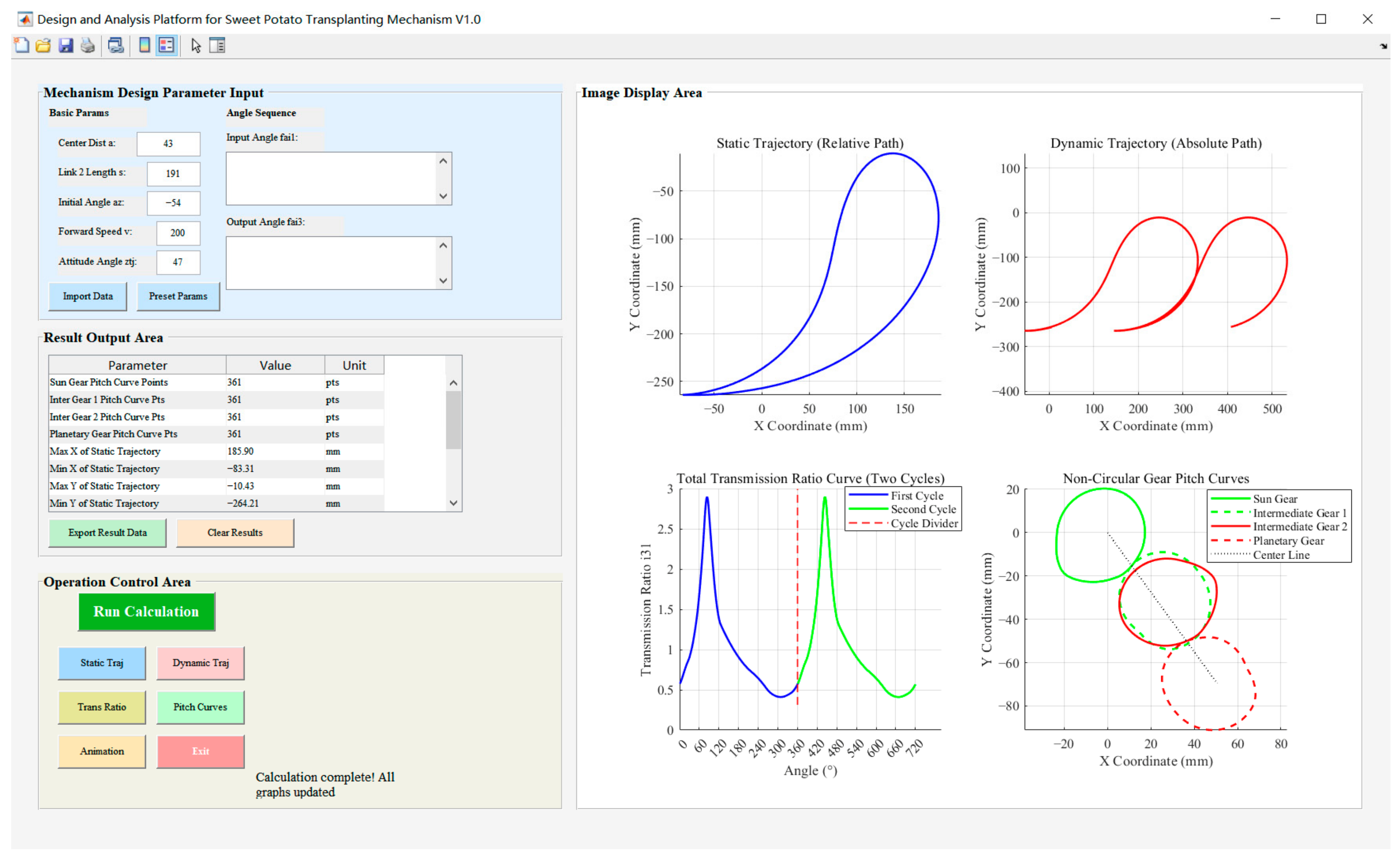
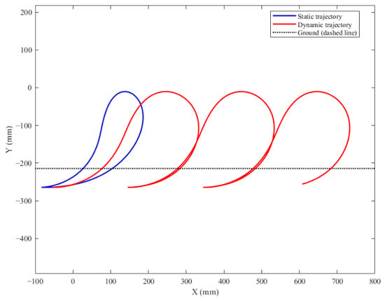
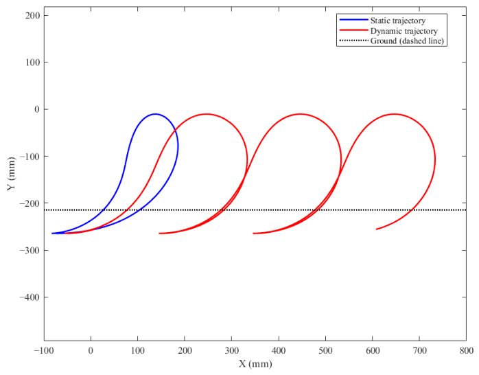
Since the non-circular gear planetary train transplanting mechanism involves a large number of design parameters [30], an auxiliary analysis and design software for the transplanting mechanism was developed based on the MATLAB R2021b platform to enhance analysis and optimization efficiency. By inputting the mechanism parameters, the kinematic solving module automatically performs the following calculation steps: (1) the transmission ratio is calculated based on the mechanism parameters using the derived equations in Section 2.4.1; (2) the pitch curve polar radii of all non-circular gears are solved using the equations in Section 2.4.2; and (3) the static and dynamic trajectories of the arm tip are computed by substituting the pitch curves into the kinematic equations in Section 2.4.2. These key results, including the transmission ratio curves, pitch curves, and the static and dynamic trajectories, are directly visualized on the platform interface (Figure 9). The software was validated by comparing the generated pitch curves and trajectories with the theoretical model derived in Section 2.3, and high consistency was observed. As shown in Figure 10, the optimal mechanism parameters were imported to obtain the pitch curves of the non-circular gears and synthesize the dynamic trajectory under the rated forward speeds of 105 mm/s at 30 r/min and 140 mm/s at 40 r/min, ensuring a consistent plant spacing of 210 mm. The results show that the actual horizontal underground length is 175 mm and the planting distance is 210 mm. All performance indicators fully satisfy the agronomic requirements for the horizontal transplanting of sweet potato seedlings.
Figure 9.
Operation interface of the auxiliary analysis and design platform for the transplanting mechanism.
Figure 10.
Static and dynamic trajectories of the transplanting mechanism.
Based on the derived pitch curves, the physical design parameters of the non-circular gears were further determined for manufacturing.
The main design parameters of the non-circular gears are as follows: the numbers of teeth for the first-stage sun gear and intermediate gear are both 23, and those for the second-stage intermediate gear and planet gear are also both 23. The equivalent module is 1.87 mm, the face width is 20 mm, and the pressure angle is 20°. The gears are made of 20CrMnTi alloy steel, and the tooth profiles were generated by slow wire-cut electrical discharge machining (WEDM) to ensure the precision of the complex non-circular profiles.
2.4. Design of the Cylindrical Cam Mechanism for the Transplanting Arm
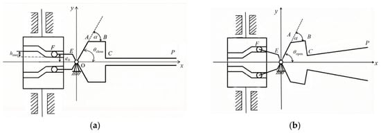
To achieve the functions of closing for seedling pick-up and opening for seedling release by the gripping claw of the transplanting arm [31], a cylindrical cam mechanism is designed to control the movement of the gripping claw. The general design methodology of the cylindrical cam mechanism is outlined as follows: as shown in Figure 11, the Cartesian coordinate equations of the gripping claw tip point P are first established. Taking the maximum distance when the two gripping claws open and the minimum distance when they close—determined based on the geometric parameters of the sweet potato seedlings—as boundary conditions, the swing angle range of the gripping claw is inversely solved. This oscillatory motion is then mapped to the follower roller center point F to determine the initial roller offset e0 and the maximum lift hmax of the cam. Subsequently, a mathematical model for the cylindrical cam profile design is established to calculate the actual cam profile curve.
Figure 11.
Schematic diagram of the cylindrical cam mechanism. (a) Closed state; (b) Opened state.
2.4.1. Determination of the Fundamental Parameters of the Cam Mechanism
A Cartesian coordinate system is established with the swing center O of the transplanting arm as the origin. The gripping claw is a rigid multi-bar linkage structure consisting of link OA, link AB, link BC, and link segment CP. The angle between the driving link OA and the positive direction of the x-axis is defined as the active swing angle , and the structural offset angle is defined as the deflection angle of link AB relative to link OA, satisfying . Consequently, r0, and hmax are determined. The lengths of the links in the gripping claw mechanism are given in Table 4.
Table 4.
Link dimensions of the gripping claw.
As shown in Figure 11, the coordinate equations of point P are derived from the geometric relationships as follows:
From Equation (31), the following relationship is deduced:
where
Regarding the follower roller center F, its coordinates depend on point E and link EF. Point E is a moving hinge point with coordinates (xE, yE), and link EF has a length of LEF, whose angle with the x-axis is determined by the mechanism position. By analyzing the segments OE and EF, the coordinate equations of point F are obtained as:
Considering that the stalk diameter of sweet potato seedlings used for transplanting typically ranges from 4.2 mm to 4.7 mm, and taking into account the flexible characteristics of the seedlings, the maximum opening width of the gripping claw is set to 50 mm, and the closed clamping width is set to 4 mm.
Substituting these boundary conditions into Equation (31) yields the angular displacement range of the driving link OA, thereby determining its maximum swing angle:
Since a rigid connection exists between the follower roller center F and the operational tip P, substituting the angular displacement corresponding to the closed state into Equation (34) yields the ordinate yF of point F at that instant. This value represents the initial roller offset of the cam mechanism:
The maximum lift of the cam is obtained by calculating the difference between the ordinates of point F at the two extreme positions (open and closed):
Substituting the link lengths from Table 4 into the aforementioned equations yields close = 63.2°, open = 71.8°, = 8.6°, e0 = 9.8 mm, and hmax = 4.6 mm.
2.4.2. Profile Curve Design of the Cam Mechanism
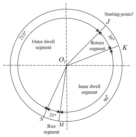
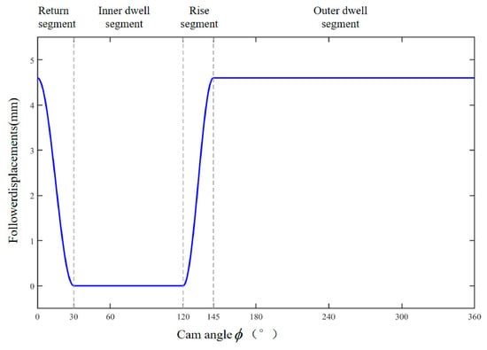
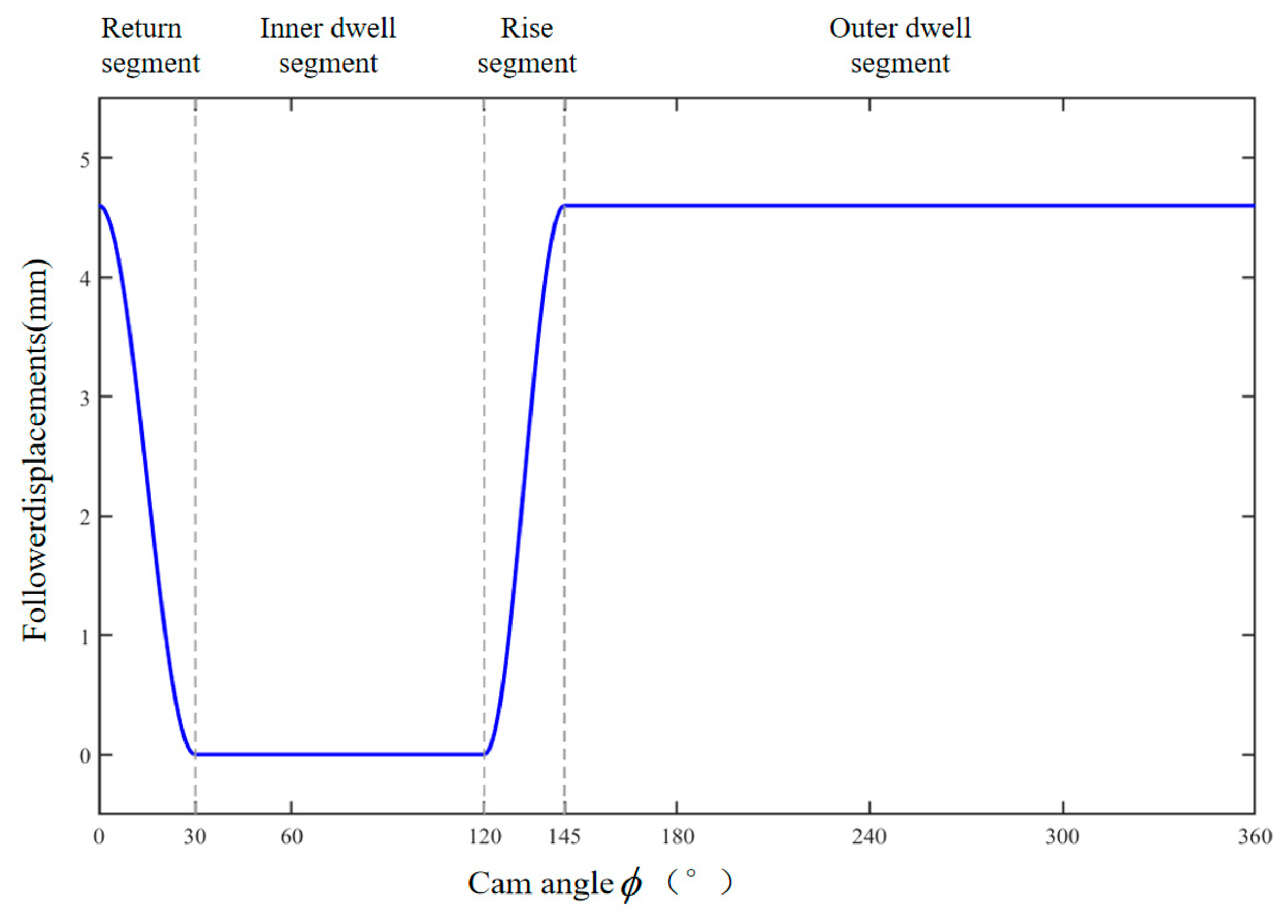
As illustrated in Figure 12, the operational cycle of the cylindrical cam is divided into four distinct phases [32]. (1) Return segment JK (cam rotation angle 0–30°): The mechanism is in the seedling pick-up phase, gripping the sweet potato seedling from the feeding device. The gripping claw gradually closes from point J and becomes completely closed at point K to achieve stable clamping of the seedling. (2) Inner dwell segment KM (cam rotation angle 30–120°): The mechanism is in the seedling conveying phase, where the gripping claw remains closed to transport the sweet potato seedling from the pick-up point to the planting point. (3) Rise segment MN (cam rotation angle 120–145°): The mechanism is in the seedling planting phase. The gripping claw gradually opens from point M and reaches its maximum opening angle at point N, completing the underground release of the sweet potato seedling. (4) Outer dwell segment NJ (cam rotation angle 145–360°): The mechanism executes an empty return stroke, during which the gripping claw remains at its maximum opened state until it passes point J to enter the next transplanting cycle.
Figure 12.
Schematic of the cam operational segments.
To avoid rigid shock of the gripping claw during the instantaneous opening and closing actions, the simple harmonic motion (SHM) law is selected to design the cam profile curve. Based on the roller lift hmax and the division of the cam operational phases, the axial displacement equation of the roller center on the developed surface of the cylindrical cam is formulated as follows:
where hmax is the maximum lift of the roller center (mm); is the cam rotation angle; and represent the return motion angle and rise motion angle, respectively; and denote the start angle and end angle of the rise segment, respectively; and r0 is the prime circle radius of the cylindrical cam, which is 20 mm.
The designed theoretical profile of the cylindrical cam is shown in Figure 13, demonstrating smooth transitions without abrupt changes across all operational segments.
Figure 13.
Theoretical profile of the cam.
2.4.3. Pressure Angle Analysis of the Cam Mechanism
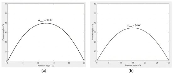
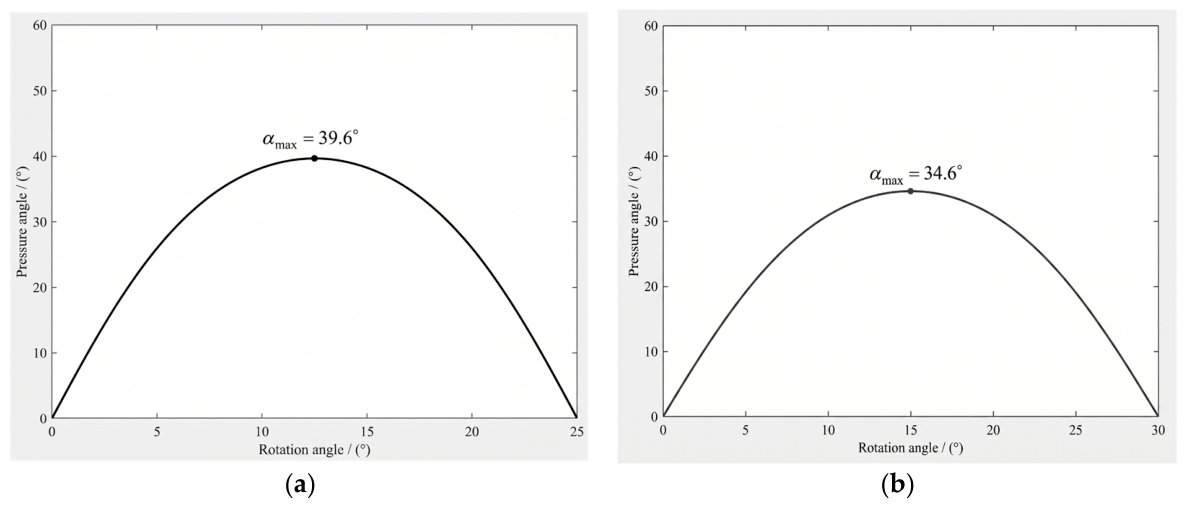
The calculation formulas for the pressure angles during the rise and return segments of the cylindrical cam are expressed as follows:
The pressure angle curves of the mechanism were calculated and plotted via MATLAB programming, with the rise and return pressure angle curves illustrated in Figure 14a and Figure 14b, respectively. For a cylindrical cam mechanism, the maximum allowable pressure angles for the rise and return strokes are specified as 45° and 80°, respectively [33]. In comparison, the maximum pressure angles of the proposed mechanism during the rise and return phases are 39.6° and 34.6°, respectively. Both values are well below the specified maximum allowable limits, thereby satisfying the design requirements.
Figure 14.
Pressure angle curves of the mechanism. (a) Rise pressure angle; (b) Return pressure angle.
3. Results
3.1. Virtual Prototype Simulation
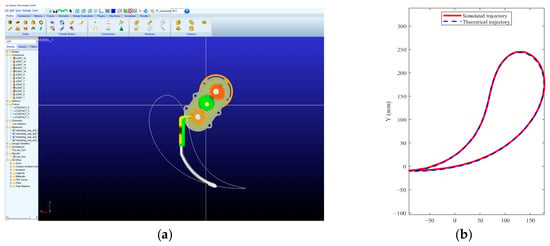
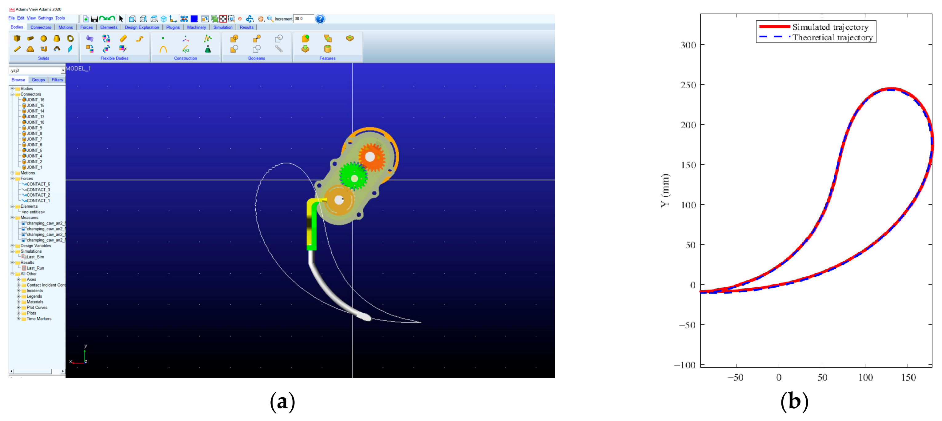
To verify the correctness of the overall mechanism design, a virtual prototype model was established based on the optimal parameters to conduct kinematic simulations [34,35]. The simulation was conducted using ADAMS 2020 software. Revolute joints were applied to the rotating components, and the gear meshing was simulated using solid-to-solid contact. The contact stiffness was set as 1.0 × 10⁴ N/mm, the force exponent was 2.2, the damping coefficient was 80.0 N·s/mm, and the penetration depth was 0.1 mm, assuming frictionless contact. The simulation duration was set to 6 s (covering three full operational cycles) with a resolution of 360 steps. The obtained static trajectory of the transplanting arm tip was compared with the theoretical trajectory, and as illustrated in Figure 15, the two exhibit excellent agreement. To quantitatively evaluate the trajectory agreement, the theoretical trajectory was first resampled using linear interpolation to match the simulation sampling points. Since the simulation and theoretical models were established in different coordinate systems, the geometric centroids of the two closed trajectories were aligned to unify the coordinate systems without altering the trajectory shape. Based on the aligned data, the maximum positional error was 11.54 mm, the mean absolute positional error was 4.04 mm, and the root mean square (RMS) trajectory error was 4.71 mm. The maximum deviations in the x and y directions were 11.32 mm and 8.68 mm, respectively. At the nine key pose points, the relative error between the simulated and theoretical posture angles ranged from 0.20% to 1.81%; the detailed comparison data are summarized in Table 5.
Figure 15.
Comparison between the simulated and theoretical static trajectories of the transplanting mechanism. (a) Simulated trajectory of the transplanting mechanism; (b) Comparison between theoretical and simulated trajectories.
Table 5.
Comparison between simulated and theoretical posture angles.
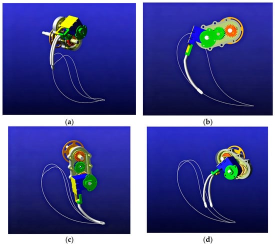
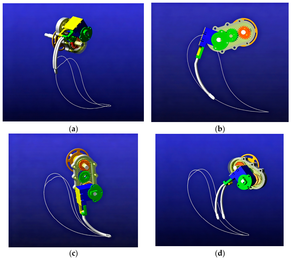
As shown in Figure 16, the operational sequence within a full working cycle demonstrates that the mechanism reliably closes to grip the seedling during the pick-up phase, maintains stable closure during the conveying phase, opens on time to release the seedling at the lowest point of the trajectory during the planting phase, and remains open during the empty return phase. The simulation results indicate that the designed mechanism can accurately reproduce the target trajectory and execute the movements of each phase according to the predetermined timing sequence, thereby proving the validity and correctness of the kinematic synthesis model and the mechanical design.
Figure 16.
Simulation of different operational phases of the virtual prototype. (a) Seedling pick-up phase; (b) Seedling conveying phase; (c) Seedling planting phase; (d) Return phase.
3.2. Prototype No-Load Test
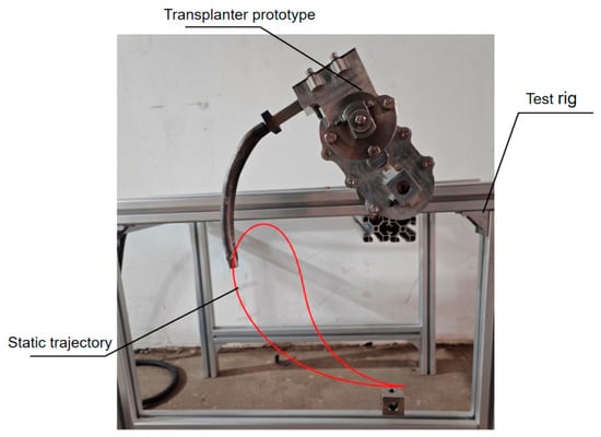
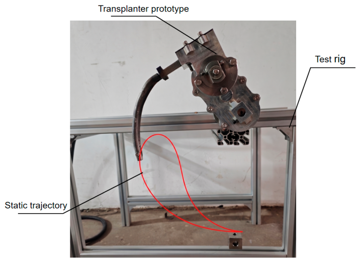
As illustrated in Figure 17, to evaluate the physical realization of the designed mechanism, a physical prototype of the transplanting mechanism was fabricated and assembled, and a dedicated test rig was constructed. Through no-load tests, the actual kinematic characteristics of the mechanism prototype were measured, while simultaneously verifying whether the actual trajectory and specific poses matched the theoretical and simulation results [36,37]. During the tests, the motion of the prototype was recorded using a Vision Research Phantom high-speed camera (Vision Research, Wayne, NJ, USA) at a sampling frequency of 500 fps, with the camera fixed perpendicular to the motion plane. The pixel-to-millimeter scale was calibrated using a ruler of known length placed in the motion plane. The recorded videos were processed using Phantom Camera Control (PCC) software (version 3.5) software to extract the actual trajectory coordinates of the arm tip. Each measurement was repeated 3 times, and the measurement uncertainty was estimated to be ±0.1° based on the camera resolution and the image-processing algorithm. A comparison between the measured and theoretical trajectories reveals excellent agreement, thereby validating the correctness of the kinematic model and the mechanical design [36].
Figure 17.
Experimental trajectory of the transplanting mechanism.
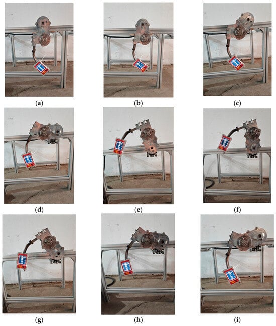
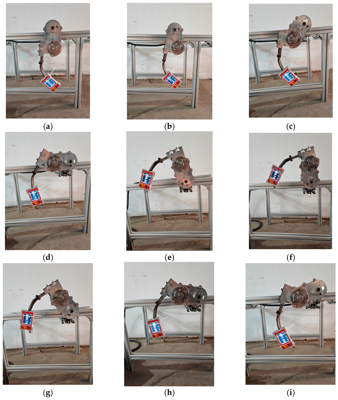
Concurrently, the posture angles of the transplanting mechanism at key positions were measured. Due to structural constraints, the posture angle of the output link BP could not be directly measured; thus, it was indirectly calculated by measuring the posture angle of the gripping claw combined with geometric relationships. Nine corresponding key pose points were selected for measurement, and the pose states at each point are displayed in Figure 18.
Figure 18.
Posture angle measurements at key positions of the transplanting mechanism. (a–i) P1 to P9.
The comparison between the theoretical and measured posture angles at key positions is summarized in Table 6. The relative error at each point ranges from only 0.14% to 0.83%, demonstrating that the actual kinematic posture of the prototype is highly consistent with the theoretical model. Specifically, the mean absolute deviations in the working zone (P1–P5) and the return zone (P6–P9) are closely balanced at 0.42° and 0.35°, respectively, proving excellent consistency in posture control throughout the entire kinematic cycle. The errors exhibit a random distribution without obvious systematic bias, which is primarily attributed to component manufacturing tolerances and prototype assembly clearances. To further evaluate the trajectory accuracy of the physical prototype, the measured trajectory was aligned with the theoretical trajectory at the starting point to eliminate coordinate system offset. Based on the aligned data, the maximum trajectory position error was 13.27 mm, the mean absolute position error was 4.48 mm, and the root mean square (RMS) trajectory error was 6.26 mm. The maximum deviations in the x and y directions were 10.16 mm and 10.79 mm, respectively. These results fully demonstrate the kinematic accuracy of the mechanism under no-load conditions, indicating that the theoretical model and mechanical design are correct.
Table 6.
Comparison between measured and theoretical posture angles.
3.3. Field Transplanting Trial
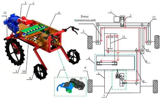
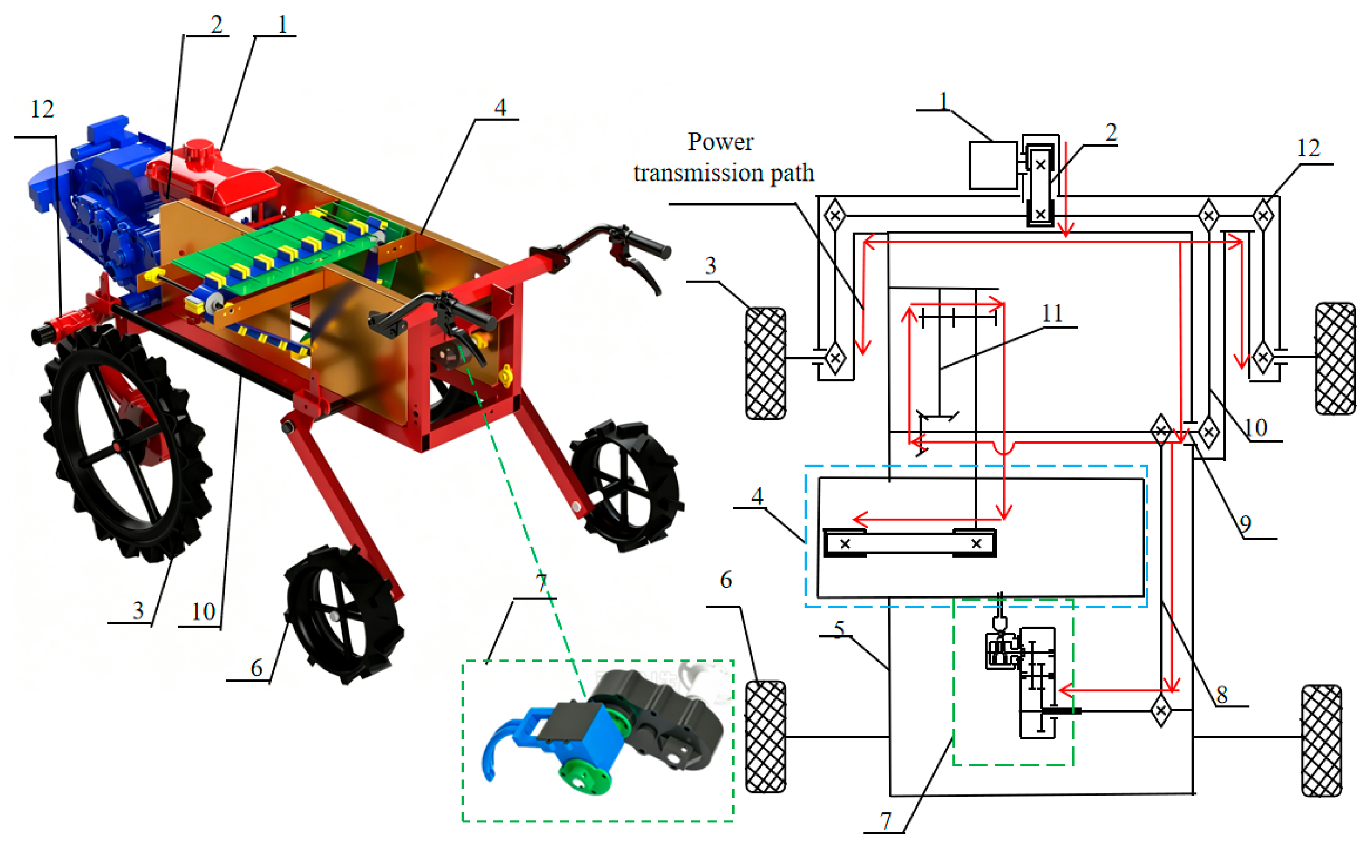
As shown in Figure 19, the power transmission system of the transplanter is primarily powered by a gasoline engine 1. The power is transmitted via the active belt pulley 2 to the main shaft where the front wheel drive chain 12 is mounted, driving the front driving wheels 3 on both sides to propel the whole machine forward, while the rear passive wheels 6 only serve as supports. Simultaneously, the power is transmitted downwards through the power distribution sprocket 10 to the central transmission shaft 9. From shaft 9, the power is further split into two branches: one branch passes through the feeding reduction gearbox 11 to drive the feeding mechanism 4 for continuous horizontal feeding; the other branch drives the transplanting mechanism 7 via the transplanting sprocket 8 to perform seedling picking and planting actions.
Figure 19.
Overall structure and power transmission system of the sweet potato transplanter prototype. 1, Gasoline engine; 2, Active belt pulley; 3, Front driving wheel; 4, Feeding mechanism; 5, Frame; 6, Rear passive wheel; 7, Transplanting mechanism; 8, Transplanting sprocket; 9, Central transmission shaft; 10, Power distribution sprocket; 11, Feeding reduction gearbox; 12, Front wheel drive chain.
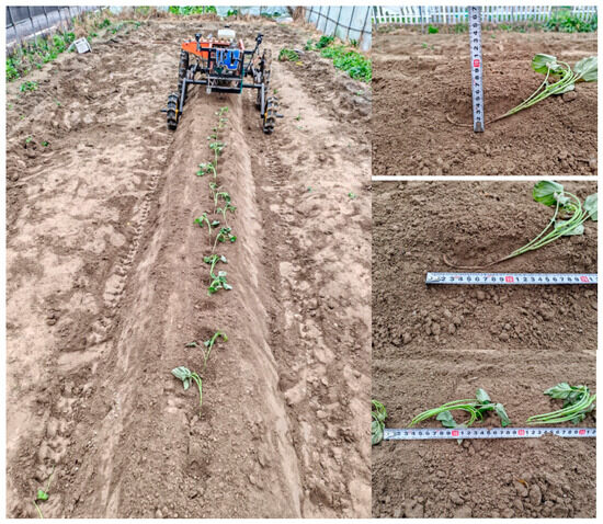
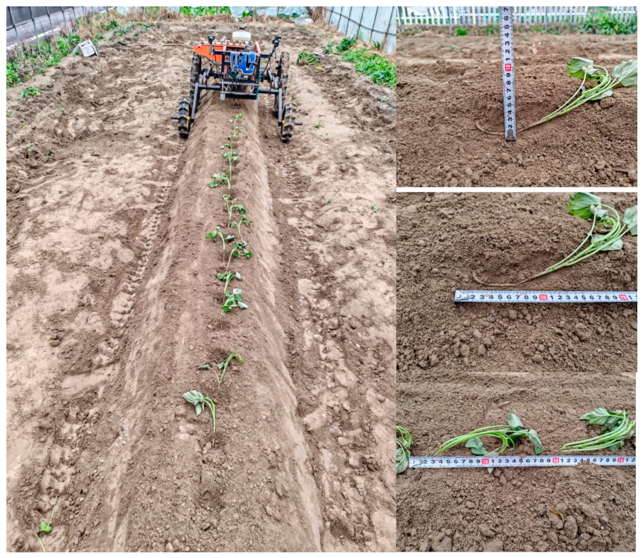
To verify whether the agronomic indicators of the transplanting mechanism satisfy the requirements of horizontal sweet potato seedling transplanting, field trials were carried out. The field trials were conducted in a sandy loam field in Xiaoshan District, Hangzhou, Zhejiang Province, China. During the trials, the soil moisture content was approximately 70% of the field water capacity. The experiments were conducted using “Yanshu 25” sweet potato seedlings, which featured an average seedling length of 255 mm and an average stalk diameter of 4.3 mm. The mechanism prototype was integrated into a complete transplanter to perform multiple rounds of transplanting operations within an experimental field characterized by a deep tillage depth of 300 mm, ridge heights of 200–300 mm, and a ridge spacing of 900 mm. The transplanting outcome is displayed in Figure 20.
Figure 20.
Outcome of the sweet potato seedling transplanting field trials.
To evaluate the operational efficiency and agronomic performance, 30 and 40 r/min were selected for the field trials, with forward speeds set to 105 mm/s and 140 mm/s, respectively, to ensure a consistent plant spacing of 210 mm. Five sets of replication trials were conducted at these two speeds, with 50 sweet potato seedlings planted per set. A transplanting operation was defined as “successful” only when the planting depth ranged from 40 to 70 mm, the underground horizontal length ranged from 150 to 200 mm and the plant spacing ranged from 180 to 220 mm. Under this definition, the loaded dynamic performance was evaluated, yielding average transplanting success rates of 91.2% and 81.2% at 30 r/min and 40 r/min, respectively, as summarized in Table 7. An independent samples t-test confirmed that the difference in success rates between the two rotational speeds was statistically significant (t = 7.09, p < 0.01). The mean ± standard deviation and coefficient of variation (CV) for planting depth, underground length, and plant spacing are reported in Table 7. Due to the aggregated nature of the field data, minimum, maximum, and confidence intervals could not be calculated.
Table 7.
Field trial results of sweet potato seedling transplanting.
The primary failure categories included missed planting, excessively deep or shallow burial, and seedling lodging. These failures were mainly attributed to two factors: (1) the sponge clamping blocks in the intermittent feeding device lost clamping force during continuous operation, causing occasional seedling slippage; and (2) local field undulations caused machine body tilting, leading to random deviations in planting position. Overall, the prototype demonstrated good field operational capability.
Subsequently, the actual agronomic performance was further assessed by measuring the planting depth, horizontal underground length, and plant spacing. The average values were 55 mm, 170 mm, and 210 mm, respectively, fully satisfying the agronomic requirements for horizontal transplanting. These field results confirm that the mechanism operates stably and reliably under actual loaded conditions.
4. Discussion
Compared with existing mechanisms, the present design offers clear advantages. Zhou et al. [16] and Ye et al. [17] developed elliptical and deformed elliptical gear planetary trains, respectively, for sweet potato transplanting, both achieving horizontal planting but relying on conventional gear profiles with limited trajectory flexibility. To clearly demonstrate the innovation of this study, Table 8 compares the proposed mechanism with the existing representative mechanisms reported in References [15,16,17].
Table 8.
Comparison between the proposed mechanism and existing representative mechanisms.
As shown in Table 8, the proposed mechanism employs 11 major moving elements, which is fewer than the crank–rocker and cam mechanism in [15] (12 elements), the elliptical planetary gear train in [16] (13 elements), and the deformed elliptical planetary gear train in [17] (14 elements). This indicates that the proposed design achieves a more compact structure with fewer moving parts, which helps reduce assembly error accumulation and improves transmission reliability. Furthermore, unlike elliptical gears constrained by fixed pitch curve equations, the proposed non-circular gear planetary train generates its pitch curves directly from Fourier coefficients, offering greater design freedom. This freedom enables the simultaneous and precise global control of 9 key target poses (with a maximum posture error of only 0.6° in Table 6), whereas the conventional geometric methods in [16,17] are limited to single-point approximation. This demonstrates a substantial improvement in multi-pose control capability.
The simulated and experimental results confirm the validity of the approach. The 0.6° deviation is acceptable for seedling pick-up and planting. The success rates of 91.2% and 81.2% are competitive with those reported in [15,16,17]. The lower success rate at higher speed stems from two factors: increased inertial forces that destabilize gripping, and reduced claw closing time that demands faster mechanism response. Moreover, the power losses in planetary gear trains increase significantly with higher rotational speeds, leading to a decrease in transmission efficiency [37]. This further deteriorates the motion accuracy of the mechanism at 40 r/min, resulting in shallower planting depths and larger plant spacing. This trend is not unique to this study—similar declines with increasing speed were observed in other planetary gear train mechanisms, including a rice transplanter [18] and a vegetable plug seedling transplanter [24], suggesting a common trade-off between speed and reliability in such systems. Thus, optimizing high-speed dynamic response is key to further performance improvement.
To address these limitations and the reviewers’ suggestions, future work will focus on five aspects: (1) optimizing the feeding device materials or implementing a force-feedback system to improve clamping stability; (2) improving the chassis suspension system or introducing attitude adaptive compensation control to mitigate the impact of terrain undulations on planting accuracy; (3) testing additional intermediate speeds (between 30 and 40 r/min) to identify the optimal operating region; (4) conducting comprehensive undercutting, interference, curvature-radius, and contact-ratio checks for the non-circular gears to further ensure reliability; and (5) verifying the general applicability of the proposed mechanism using more sweet potato cultivars.
5. Conclusions
- (1)
- A Fourier series-based kinematic synthesis method for transplanting mechanisms is proposed. The optimal mechanism parameters (r = 4.51 mm, a = 86.16 mm, b = 190.97 mm) were obtained, and simulation results show that the relative errors between simulated and theoretical posture angles at nine key positions range from 0.20% to 1.81%.
- (2)
- Physical no-load tests demonstrate that the relative errors between measured and theoretical posture angles range from 0.14% to 0.83%, consistent with the simulation results.
- (3)
- Field trial results show that under rotational speeds of 30 r/min and 40 r/min, the average transplanting success rates are 91.2% and 81.2%, respectively, and the planting depth, horizontal underground length, and plant spacing all meet the agronomic requirements.
Author Contributions
Conceptualization, B.Y., T.T. and J.S.; methodology, J.S. and B.Y.; software, J.S.; validation, J.S., Z.G. and M.Y.; formal analysis, J.S. and X.Y.; investigation, J.S. and Z.G.; resources, B.Y. and T.T.; data curation, J.S.; writing—original draft preparation, J.S.; writing—review and editing, B.Y., T.T. and X.Y.; visualization, J.S.; supervision, B.Y. and T.T.; project administration, B.Y.; funding acquisition, B.Y. All authors have read and agreed to the published version of the manuscript.
Funding
This research was funded by Zhejiang Provincial Natural Science Foundation of China (Grant No. LD24E050007) and Changshan County Science and Technology Plan Project (Grant No. 2026B02).
Institutional Review Board Statement
Not applicable.
Data Availability Statement
All data generated or analyzed during this study are included in this published article.
Acknowledgments
The authors would like to thank the members of the research group for their support in the prototype manufacturing and field experiments.
Conflicts of Interest
Xuefu Yu was employed by Zhejiang Changshan Mingrui Electromechanical Co., Ltd.; the remain authors declared no conflicts of interest. The funders had no role in the design of the study; in the collection, analyses, or interpretation of data; in the writing of the manuscript; or in the decision to publish the results.
References
- Tong, C.; Ru, W.D.; Wu, L.H.; Wu, W.C.; Bao, J.S. Fine Structure and Relationships with Functional Properties of Pigmented Sweet Potato Starches. Food Chem. 2020, 311, 126011. [Google Scholar] [CrossRef] [Scilit]
- Liu, Z.; Zheng, W.; Lv, Z.; Pan, J. Optimization and Experimental Analysis of Multi-Path Sweet Potato Transplanter Device. Sci. Rep. 2025, 15, 11164. [Google Scholar] [CrossRef] [Scilit]
- Yan, W.; Zhang, W.; Hu, M.; Ji, Y.; Li, K.; Ren, Z.; Wu, C. Design and Experiment of Compound Transplanter for Sweet Potato Seedling Belt. Agriculture 2024, 14, 1738. [Google Scholar] [CrossRef] [Scilit]
- Zhu, Q.; Wang, G.; Zhang, W.; Hu, L.; Zhang, T.; Mu, G. Research Progress on Key Technologies and Equipments of Sweet Potato Planting Mechanization. J. Chin. Agric. Mech. 2025, 46, 36–42. [Google Scholar]
- Zhu, B.B.; Lv, Z.Q. Design of Sweet Potato Bare Root Seedling Transplanter with Clamp Type. J. Agric. Mech. Res. 2018, 40, 120–123+161. (In Chinese) [Google Scholar] [CrossRef]
- Mechanical Transplanter Company. 814F Trailer Transplanter. 2025. Available online: https://mechanicaltransplanter.com/pages/transplanters (accessed on 19 August 2026).
- Ferrari Growtech. FPP EVO Mechanical Transplanter. 2025. Available online: https://ferrarigrowtech.com/en/finger-transplanters/26-fpp-evolution-short-chain-finger-transplanter.html (accessed on 19 August 2026).
- He, T.; Liu, H.; Shi, Y.; Wang, B.; Li, H.; Zhang, X.; Shi, S. Efficacy of Mini Wheel-Driven Sweet Potato Transplanting Machine for Mulched Raised Beds. Agriculture 2025, 15, 2434. [Google Scholar] [CrossRef] [Scilit]
- Li, H.; Wang, B.; Shi, S.; Zhou, J.; Shi, Y.; Liu, X.; Liu, H.; He, T. Response of Crop Performance and Yield of Spring Sweet Potato (Ipomoea batatas [L.] Lam) as Affected by Mechanized Transplanting Properties. Agronomy 2023, 13, 1611. [Google Scholar] [CrossRef] [Scilit]
- He, T.; Li, H.; Shi, S.; Liu, X.; Liu, H.; Shi, Y.; Jiao, W.; Zhou, J. Preliminary Results Detailing the Effect of the Cultivation System of Mulched Ridge with Double Row on Solanaceous Vegetables Obtained by Using the 2ZBX-2A Vegetable Transplanter. Appl. Sci. 2023, 13, 1092. [Google Scholar] [CrossRef] [Scilit]
- Cheng, B.; Wu, H.; Zhu, H.; Liang, J.; Miao, Y.; Cui, Y.; Song, W. Current Status and Analysis of Key Technologies in Automatic Transplanters for Vegetables in China. Agriculture 2024, 14, 2168. [Google Scholar] [CrossRef] [Scilit]
- Shentu, L.F.; Tang, L.J.; Sun, X.Z.; Zhang, J.J.; Zhang, Z.Y. Design and Simulation of Planting Mechanism of Finger-Clip Sweet Potato Transplanter. Jiangsu Agric. Sci. 2018, 46, 223–226. (In Chinese) [Google Scholar] [CrossRef]
- Liu, Z.; Lv, Z.; Zheng, W.; Yang, Y.; Wang, Y. Trajectory Control of Two-Degree-of-Freedom Sweet Potato Transplanting Robot Arm. IEEE Access 2022, 10, 26294–26306. [Google Scholar] [CrossRef] [Scilit]
- Li, H.; He, T.F.; Liu, H.; Wang, J.C.; Song, L.C. Development of Profiled Cutting Transplanting Machine for Sweet Potato on Film in Hilly and Mountainous Areas. Trans. Chin. Soc. Agric. Eng. 2023, 39, 26–35. (In Chinese) [Google Scholar]
- Zhang, W.Z.; Zhu, Q.; Ge, D.M.; Zhang, T.; Liu, J.G. Design and Experiment of the Side Insertion Horizontal Transplanting Device for Sweet Potato (Ipomoea batatas Lam.) Seedlings on Mulch Film. Int. J. Agric. Biol. Eng. 2023, 16, 148–157. [Google Scholar] [CrossRef] [Scilit]
- Zhou, H.L.; Yan, M.Y.; Xue, H.B.; Sun, L.J.; Wang, L. Design and Tests on the Transplanting Mechanism of Sweet Potato with Elliptical Gear Planetary Gear Train. J. Zhejiang Sci.-Tech Univ. Nat. Sci. Ed. 2025, 53, 96–104. (In Chinese) [Google Scholar]
- Ye, B.L.; Ye, Y.; Zhou, H.L.; Yu, G.H.; Wang, L. Design and Experimental Research on the Sweet Potato Seedling Transplanting Mechanism of the Planetary Gear Train with Deformed Elliptical Gear Transmission. Int. J. Agric. Biol. Eng. 2024, 17, 91–99. [Google Scholar] [CrossRef] [Scilit]
- Stanojević, M.; Milojević, S.; Marić, D.; Stojanović, B. Influence of Gears and Oil Levels Upon Efficiency of Ravigneaux Gearset. Teh. Vjesn. 2025, 32, 2048–2055. [Google Scholar] [CrossRef] [Scilit]
- Li, H.; He, T.; Liu, H.; Shi, S.; Wang, B.; Zhou, J.; Liu, X.; Wei, G.; Zhang, R. Efficacy of Sweet Potato Transplanting Machine for Different Cultivation Systems in Northern China. Agriculture 2022, 12, 1184. [Google Scholar] [CrossRef] [Scilit]
- Li, X.G.; Zhang, L.J.; Wei, S.M. Algebraic Solution for Path Synthesis of Planar Stephenson-III Six-Bar Linkage. Adv. Eng. Sci. 2021, 53, 158–164. (In Chinese) [Google Scholar]
- Yu, C.N.; Wang, Y.; Dai, Z.L.; Yao, K.; Wu, Y.H.; Jia, J.M.; Chen, J.N. Synthesis and Application of Reduced-Dimension Optimization for Rigid-Body Guidance of Stephenson-III Six-Bar Linkages on the Basis of Fourier Harmonic Characteristics. J. Mech. Robot. 2026, 18, 011006. [Google Scholar] [CrossRef] [Scilit]
- Zeng, G.; Wang, L.; Yu, G.H.; Jin, X.J.; Zhou, H.L. A Synthesis Method of Open-Chain Coupled Serial Linkage Mechanism Fusing Trajectory and Posture. Int. J. Pattern Recognit. Artif. Intell. 2024, 38, 2458001. [Google Scholar] [CrossRef] [Scilit]
- Ye, J.; Zhao, X.; Wang, Y.; Yu, G.H.; Sun, L. A Novel Planar Motion Generation Method Based on the Synthesis of Planetary Gear Train with Noncircular Gears. J. Mech. Sci. Technol. 2019, 33, 4939–4949. [Google Scholar] [CrossRef] [Scilit]
- Qian, Y.H.; Zhong, H.; Wang, T.; Wang, L.M. An Improved Fourier-Based Method for Path Generation of Planar Four-Bar Linkages Without Prescribed Timing. Machines 2024, 12, 299. [Google Scholar] [CrossRef] [Scilit]
- Chen, X.A.; Chen, H. Analytical Geometry Method of Planetary Gear Trains. Sci. China Technol. Sci. 2012, 55, 1007–1021. [Google Scholar] [CrossRef] [Scilit]
- Wang, L.; Lin, Z.W.; Zhou, Z.H.; Yu, G.H.; Yang, Z.Y.; Yu, X.F.; Ye, B.L. Design and Experiment of a Vegetable Plug Seedling Planting Mechanism Combining Non-Circular Gear System and Multi-Link. Int. J. Agric. Biol. Eng. 2025, 18, 124–134. [Google Scholar] [CrossRef] [Scilit]
- Zhao, X.; Liao, H.W.; Ma, X.X.; Dai, L.; Yu, G.H.; Chen, J.N. Design and Experiment of Double Planet Carrier Planetary Gear Flower Transplanting Mechanism. Int. J. Agric. Biol. Eng. 2021, 14, 55–62. [Google Scholar] [CrossRef] [Scilit]
- Sun, L.; Xu, H.C.; Zhou, Y.Z.; Shen, J.H.; Yu, G.H.; Hu, H.F.; Miao, Y.J. Kinematic Synthesis and Simulation of a Vegetable Pot Seedling Transplanting Mechanism with Four Exact Task Poses. Int. J. Agric. Biol. Eng. 2023, 16, 85–95. [Google Scholar] [CrossRef] [Scilit]
- Ye, B.L.; Wang, X.W.; Tang, T.; Zeng, G.J.; Zheng, Y. Design and Tests of a planetary non-circular gear train transplanting mechanism for flower plug seedlings. Mech. Sci. 2025, 16, 303. [Google Scholar] [CrossRef] [Scilit]
- Zhou, M.; Wei, Z.; Wang, Z.; Sun, H.; Wang, G.; Yin, J. Design and Experimental Investigation of a Transplanting Mechanism for Super Rice Pot Seedlings. Agriculture 2023, 13, 1920. [Google Scholar] [CrossRef] [Scilit]
- Xiao, L.P.; Pu, C.; Cai, J.P.; Lin, J.L.; Cai, H.; Huang, L.L.; Deng, F.Q. Design and Simulation Analysis of Seedling Picking Mechanism of Pot Seedling Transplanter. J. Phys. Conf. Ser. 2019, 1314, 012084. [Google Scholar] [CrossRef] [Scilit]
- Osanyinpeju, K.L.; Aderinlewo, A.A.; Dairo, O.U.; Adetunji, O.R.; Ajisegiri, E.S. Development of the Shape of the Cam Profile of Mechanical Yam Vibrator Using Cycloid Motion. Sustain. Eng. Innov. 2022, 4, 34–45. [Google Scholar] [CrossRef] [Scilit]
- Yang, K.Z.; Cheng, G.Y.; Li, Z.S. Fundamentals of Mechanical Design; Higher Education Press: Beijing, China, 2006. (In Chinese) [Google Scholar]
- Ali, M.R.; Reza, M.N.; Samsuzzaman; Habineza, E.; Haque, M.A.; Kang, B.-S.; Chung, S.-O. Kinematic Analysis of a Cam-Follower-Type Transplanting Mechanism for a 1.54 kW Biodegradable Potted Cabbage Transplanter. Machines 2024, 12, 925. [Google Scholar] [CrossRef] [Scilit]
- Habineza, E.; Ali, M.R.; Reza, M.N.; Lee, K.-H.; Park, S.-H.; Lee, D.-H.; Chung, S.-O. Kinematic Modeling and Preliminary Field Evaluation of a Link-Driven Hopper Planting Mechanism for a 3.4 kW Walking-Type Pepper Transplanter. Machines 2025, 13, 1074. [Google Scholar] [CrossRef] [Scilit]
- Reza, M.N.; Islam, M.N.; Chowdhury, M.; Ali, M.; Islam, S.; Kiraga, S.; Lim, S.-J.; Choi, I.-S.; Chung, S.-O. Kinematic Analysis of a Gear-Driven Rotary Planting Mechanism for a Six-Row Self-Propelled Onion Transplanter. Machines 2021, 9, 183. [Google Scholar] [CrossRef] [Scilit]
- Wang, L.; Sun, L.; Huang, H.M.; Yu, Y.X.; Yu, G.H. Design of Clamping-Pot-Type Planetary Gear Train Transplanting Mechanism For Rice Wide–Narrow-Row Planting. Int. J. Agric. Biol. Eng. 2021, 14, 62–71. [Google Scholar] [CrossRef] [Scilit]

Disclaimer/Publisher’s Note: The statements, opinions and data contained in all publications are solely those of the individual author(s) and contributor(s) and not of MDPI and/or the editor(s). MDPI and/or the editor(s) disclaim responsibility for any injury to people or property resulting from any ideas, methods, instructions or products referred to in the content. |
© 2026 by the authors. Licensee MDPI, Basel, Switzerland. This article is an open access article distributed under the terms and conditions of the Creative Commons Attribution (CC BY) license.