


Abstract
With the rapid development of unmanned agricultural machinery technology, the accuracy and stability of agricultural machinery path tracking have become key challenges in achieving precision agriculture. To address the issues of insufficient accuracy and stability in path tracking for rice transplanters in paddy fields, this study proposes a composite control strategy that integrates the extended line-of-sight (LOS) guidance law with an adaptive fuzzy sliding mode control law. By establishing a two degree of freedom dynamic model of the rice transplanter, two extended state observers are designed to estimate the longitudinal and lateral velocities of the rice transplanter in real time. A dynamic compensation mechanism for the sideslip angle is introduced, significantly enhancing the adaptability of the traditional look-ahead guidance law to soil slippage. Furthermore, by combining the approximation capability of fuzzy systems with the adaptive adjustment method of sliding mode control gains, a front wheel steering control law is designed to suppress complex environmental disturbances. The global stability of the closed-loop system is rigorously verified using the Lyapunov theory. Simulation results show that compared to the traditional Stanley algorithm, the proposed method reduces the maximum lateral error by 38.3%, shortens the online time by 23.9%, and decreases the steady-state error by 15.5% in straight-line path tracking. In curved path tracking, the lateral and heading steady-state errors are reduced by 19.2% and 14.6%, respectively. Field experiments validate the effectiveness of this method in paddy fields, with the absolute lateral error stably controlled within 0.1 m, an average error of 0.04 m, and a variance of 0.0027 m2.
1. Introduction
With the rapid development of agricultural automation and intelligent technology, high-precision path tracking of agricultural machinery has become a core requirement for autonomous driving [1,2,3,4,5]. As a key equipment for rice planting, the path tracking accuracy of the rice transplanter directly affects operational efficiency and crop yield [6,7,8,9]. However, under complex working conditions in paddy fields, factors such as soil sliding, longitudinal velocity fluctuations, and environmental disturbances significantly reduce the robustness and stability of traditional path-tracking algorithms [10,11,12]. Although existing research has made some progress in the field of agricultural machinery path tracking, there are still significant shortcomings in adaptability in complex agricultural environments [13,14,15].
In recent years, the academic community has conducted extensive and in-depth research on agricultural machinery path-tracking control [16,17]. Luo et al. [18] conducted path-tracking experiments using the PID algorithm. The results showed that the average straight-line path tracking error was less than 10 cm, but there were significant errors at bends. Tang et al. [19] designed a pure tracking method for rice transplanters. It has poor adaptability and requires calculating the forward distance at different vehicle speeds. Chi et al. [20] designed an autonomous driving controller based on a simplified rice transplanter model, vehicle kinematic equations, and model predictive control algorithm. Lin et al. [21] established a four-wheel out-phase steering kinematic model for paddy field crop protection machines, which includes slip interference and heading angle interference. Then, they proposed a linear path-tracking steering control algorithm based on the global sliding mode control and the fast power law approach. Ding et al. [22] optimized the sliding mode controller, effectively improving the convergence speed and adaptability of the algorithm, achieving high-precision path tracking of tractors in simulation environments.
At present, mainstream path-tracking algorithms include the PID control algorithm, the pure tracking algorithm, the Stanley algorithm, the LQR algorithm, the MPC algorithm, and the sliding mode control algorithm [23,24,25,26,27,28]. The parameters of the PID control algorithm need to be repeatedly adjusted and verified, which consumes a lot of time [29]. The pure tracking algorithm is only applicable to working conditions with low vehicle speeds and smooth roads and has strict requirements for the value of the forward distance. The Stanley algorithm has weak robustness and does not have the ability to resist random environmental disturbances. The LQR algorithm control ignores vehicle dynamics constraints and is prone to sideslip during rapid turns. With the improvement in control performance requirements and the increase in constraints and dimensions of the controlled model object, the computational difficulty of online rolling optimization for MPC algorithm increases sharply. The sliding mode variable structure control, as a typical nonlinear feedback control method, is widely used in vehicle path-tracking control systems. Its advantages lie in the flexible design of sliding mode surfaces, strong parameter perturbation resistance, and fast response speed, but it also suffers from chattering problems. In recent years, line-of-sight (LOS) guidance has been highly favored in path-tracking control [30]. Breivik et al. [31] designed a method that combines LOS guidance law with backstepping technology for linear and circular path tracking. Wang et al. [32] proposed a LOS guidance law that varies with longitudinal velocity and developed a robust heading tracking controller based on an adaptive fuzzy observer to ensure uniform ultimately bounded heading errors. Xiang et al. [33] online adjusted the forward distance of LOS guidance law through path curvature to improve its adaptability to curved paths. In the classic LOS guidance law mentioned above, precise sideslip angle [10] is often difficult to measure directly.
From the above analysis, it can be seen that the path-tracking control algorithms currently used on agricultural machinery are mainly designed based on kinematic models. Most of them assume that agricultural machinery is being driven in an ideal environment. If these algorithms are applied in dry fields and other environments without obvious sideslip, the path-tracking control error can meet the requirements of agricultural applications. The rice transplanter works in the paddy field environment. The soil conditions are wet and slippery, making it prone to lateral slip. Based on the mechanical model of the rice transplanter, the path-tracking control algorithm with lateral slip compensation can effectively improve the driving accuracy of the rice transplanter under complex working conditions.
To improve the path tracking accuracy and anti-interference ability of path-tracking controllers for rice transplanters, this paper proposes a composite control method based on extended LOS guidance and adaptive fuzzy sliding mode. Firstly, perform a dynamic analysis of the rice transplanter and establish its dynamic model. Secondly, develop an adaptive path-tracking control algorithm with sideslip compensation. Finally, conduct simulation and field experiments to verify the tracking accuracy and adaptability of the designed path-tracking control method. The main innovations of this article are as follows. Utilizing two extended state observers to estimate the longitudinal and lateral velocities of the rice transplanter in real time and introducing a dynamic compensation mechanism for lateral slip angle, the adaptability of the guidance system to soil slip is significantly improved. By utilizing the approximation ability of fuzzy systems and the adaptive adjustment method of sliding mode control gain, complex environmental disturbances are suppressed and chattering is reduced. This work not only provides new ideas for path tracking problems in complex agricultural environments but also promotes the application of adaptive control and observer fusion design in the field of agricultural robots. Subsequent chapters will provide detailed discussions on dynamic modeling, controller design, and experimental verification.
2. Materials and Methods
2.1. Path-Tracking Control Method of Rice Transplanter
2.1.1. Mechanistic Model
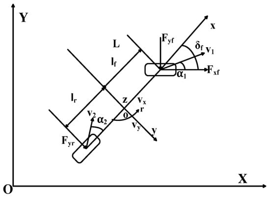
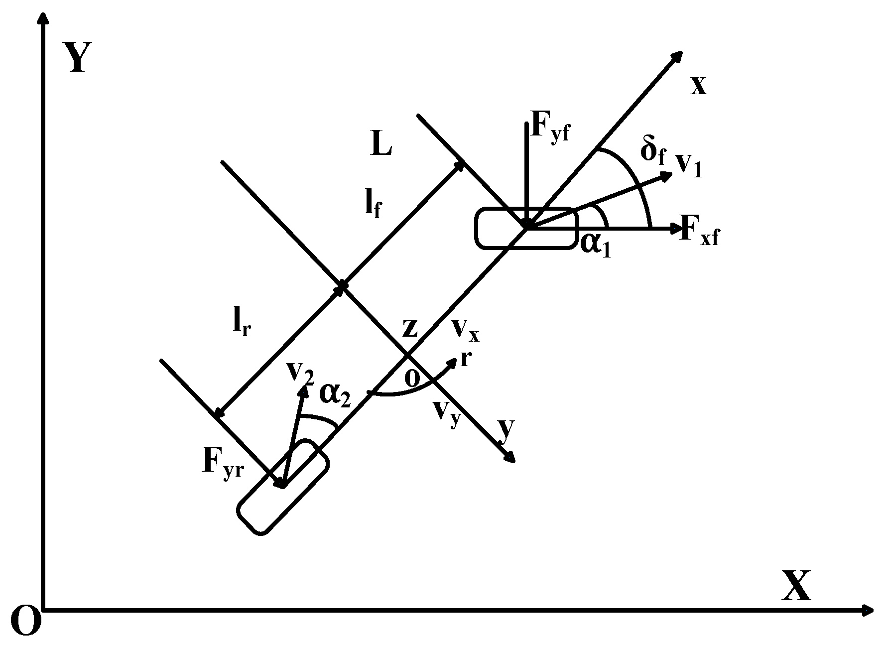
Considering that the complex working environment can cause strong interference to the running state of the rice transplanter, this paper establishes a vehicle dynamics model of the rice transplanter suitable for complex working conditions. In order to improve the real-time performance of the control system and reduce the computational complexity of the controller, the following assumptions are made for the model: only consider the lateral and yaw motions of the rice transplanter, assume that the steering angles of the left and right wheels of the rice transplanter are equal, and ignore the load transfer and aerodynamic effects. The simplified two-freedom model of rice transplanter is shown in Figure 1.
Figure 1.
Two-freedom model of rice transplanter.
According to Newton’s second law, perform dynamic analysis on the two-freedom model of rice transplanter.
where is the longitudinal velocity, is the lateral velocity, is the yaw rate, is the front-wheel steering angle, is the lateral force exerted on the front wheels, is the longitudinal force exerted on the front wheels, is the lateral force exerted on the rear wheels, is the distance from centroid to front axle, is the distance from centroid to rear axle, is the moment of inertia of the z-axis, and is the mass of rice transplanter.
Considering that both and act in the linear region during the path tracking process of the rice transplanter mentioned in this article, the linear relationship between lateral force and lateral deviation angle can be obtained as shown in Equation (2).
where is the sideslip angle of the front wheels, is the sideslip angle of the rear wheels, is the lateral stiffness of the front wheels, and is the lateral stiffness of the rear wheels.
Combining the small angle approximation method, the calculation formulas for and are shown in Equation (3).
The state space equation of the rice transplanter dynamics model can be obtained from Equations (1)–(3).
2.1.2. Basic Principles of Line-of-Sight (LOS) Guidance Method
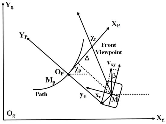
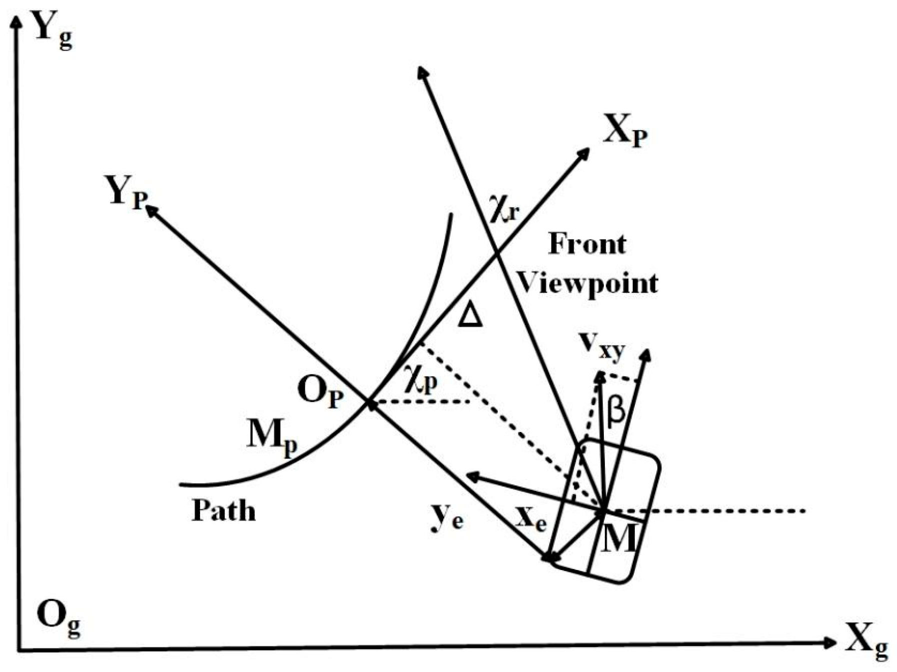
As shown in Figure 2, is the ground coordinate system and represents the current centroid position of the rice transplanter. The centroid position is denoted as . is the SF coordinate system. The expected path vector is . is the path parameter, and , are quadratic differentiable with respect to . The tangential angle of the expected path is shown in Equation (5).
Figure 2.
Schematic diagram of LOS guidance.
The transformation matrix from ground coordinate system to SF coordinate system is shown in Equation (6).
It can be seen from Figure 2 that and , respectively, represent the components of the position error between the current position and the expected path position of the rice transplanter in the SF coordinate system. The tracking error is shown in Equation (7).
Take the derivative on both sides of Equation (7), as shown in Equation (8).
where is the velocity of the rice transplanter in position .
To achieve the tracking of the expected path by the rice transplanter, the actual heading angle of the rice transplanter needs to be equal to the expected heading angle. According to Figure 2, the expected heading angle is shown in Equation (9).
where is the expected heading angle, is the sideslip angle of the rice transplanter, and is the front view distance.
2.1.3. Design of Extended Line-of-Sight (LOS) Guidance Method
The basic principle of LOS guidance method indicates that the convergence of tracking error can be achieved by adjusting the heading angle of the rice transplanter. During the path tracking process of the rice transplanter, the positions , heading angle , and tracking errors and can be measured, but the longitudinal velocity and lateral velocity are usually difficult to measure. In order to solve the above problem, this paper uses the known position, angle, and tracking error in the LOS guidance method to design two extended state observers. The designed observers can estimate the real-time longitudinal velocity and lateral velocity of the rice transplanter during path tracking and then compensate for the lateral slip angle of the rice transplanter.
Assuming that the rice transplanter can accurately track the desired heading angle during path tracking, Equation (8) can be expressed as Equation (10).
The designed extended state observers are shown in Equations (11) and (12).
where is the estimated value of longitudinal velocity, is the estimation of lateral velocity, is the auxiliary state of state observer 1, is the auxiliary state of state observer 2, and is the observer gain.
The estimation error of longitudinal velocity and lateral velocity is shown in Equation (13).
Combining Equations (11) and (12), taking the derivative of Equation (13) yields Equation (14).
Substituting Equation (13) into Equation (10) yields Equation (15).
In summary, the extended LOS guidance system consists of Equations (14) and (15). To make the system input stable, the expected heading angle update formula is shown in Equation (16).
The adaptive update law of the path parameter is shown in Equation (17).
where and are the controller gains. In the equation, is a positive value, and and are, respectively, taken as 8 and 4 times the length of the vehicle body.
To demonstrate the stability of the extended LOS guidance system mentioned above, a Lyapunov function is constructed as shown in Equation (18).
By taking the derivative of Equation (18), Equation (19) can be obtained.
By utilizing the properties of trigonometric functions and mean inequality, Equation (19) can be simplified to obtain Equation (20).
Choosing the appropriate control gain yields Equation (21).
where is a positive constant. It is easy to prove that when , . Therefore, the extended LOS guidance method proposed in this article is stable.
2.1.4. Design of Adaptive Fuzzy Sliding Mode Controller
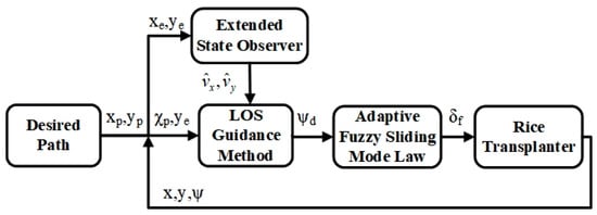
In the process of path tracking, the extended LOS guidance method is used to obtain the desired heading angle, and the adaptive fuzzy sliding mode controller is used to achieve tracking control of the rice transplanter for the desired heading angle. The path-tracking control system consists of an extended LOS guidance method and an adaptive fuzzy sliding mode controller, as shown in Figure 3. In path-tracking control, only the lateral and yaw motions of the rice transplanter are considered. Based on the relationship between heading angle and heading angular velocity, combined with the dynamic model of the rice transplanter, the state equation is obtained as shown in Equation (22).
where Q is equal to .
Figure 3.
Schematic diagram of the path-tracking control system.
From Equation (22), Equation (23) can be obtained.
Based on the principle of linear feedback control, the control law for the front-wheel angle of the rice transplanter is obtained as shown in Equation (24).
where is the heading angle error, and . Both and are greater than zero.
Due to the difficulty in measuring the lateral velocity of the rice transplanter, it is difficult to implement the front-wheel control law . In order to solve the above problems, based on the universal approximation property of fuzzy systems, there is an optimal fuzzy control system that can approximately represent the control law of the front-wheel steering angle.
where is the parameter vector, and . is the fuzzy vector, and . is the weight of fuzzy rules. is the fuzzy approximation error. Among them, and .
The sliding surface is shown in Equation (26).
The designed front-wheel steering angle adaptive fuzzy sliding mode control law is shown in Equation (27).
where is an estimated value of , is an estimated value of , is a positive value, and is a positive value.
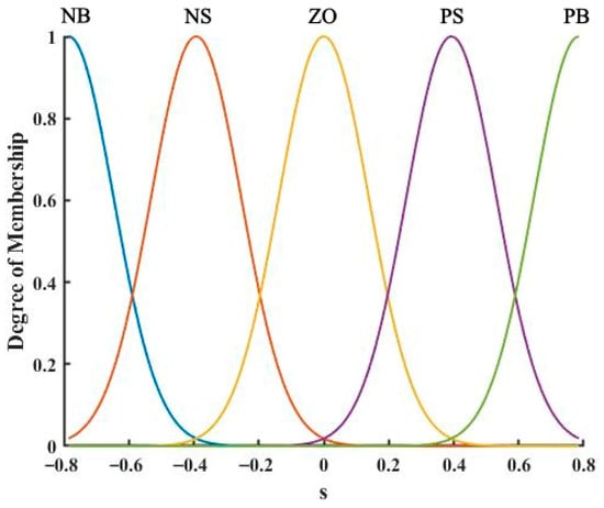
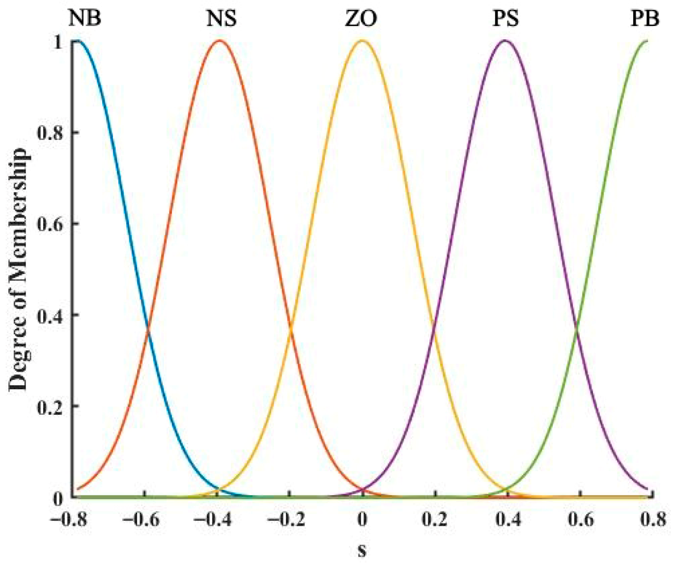
The membership function is shown in Figure 4. The fuzzy language variables NB, NS, ZO, PS, and PB, respectively, represent the negative large, negative small, zero, positive small, and positive large states of variables in the fuzzy set.
Figure 4.
Membership function of the path-tracking control system.
To demonstrate the stability of the adaptive fuzzy sliding mode control law proposed in this article, a Lyapunov function was constructed as shown in Equation (28).
where is the estimated error of , and . is the estimated error of , and .
By taking the derivative of Equation (28), Equation (29) can be obtained.
When , ; When , ; When . As can be seen from the above analysis, . Therefore, the adaptive fuzzy control law proposed in this article is stable.
2.2. Materials and Experiments
2.2.1. Autonomous Driving System Design of Rice Transplanter
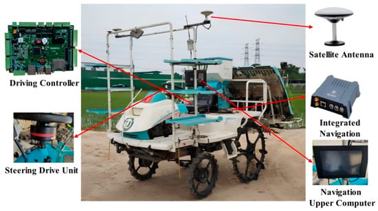
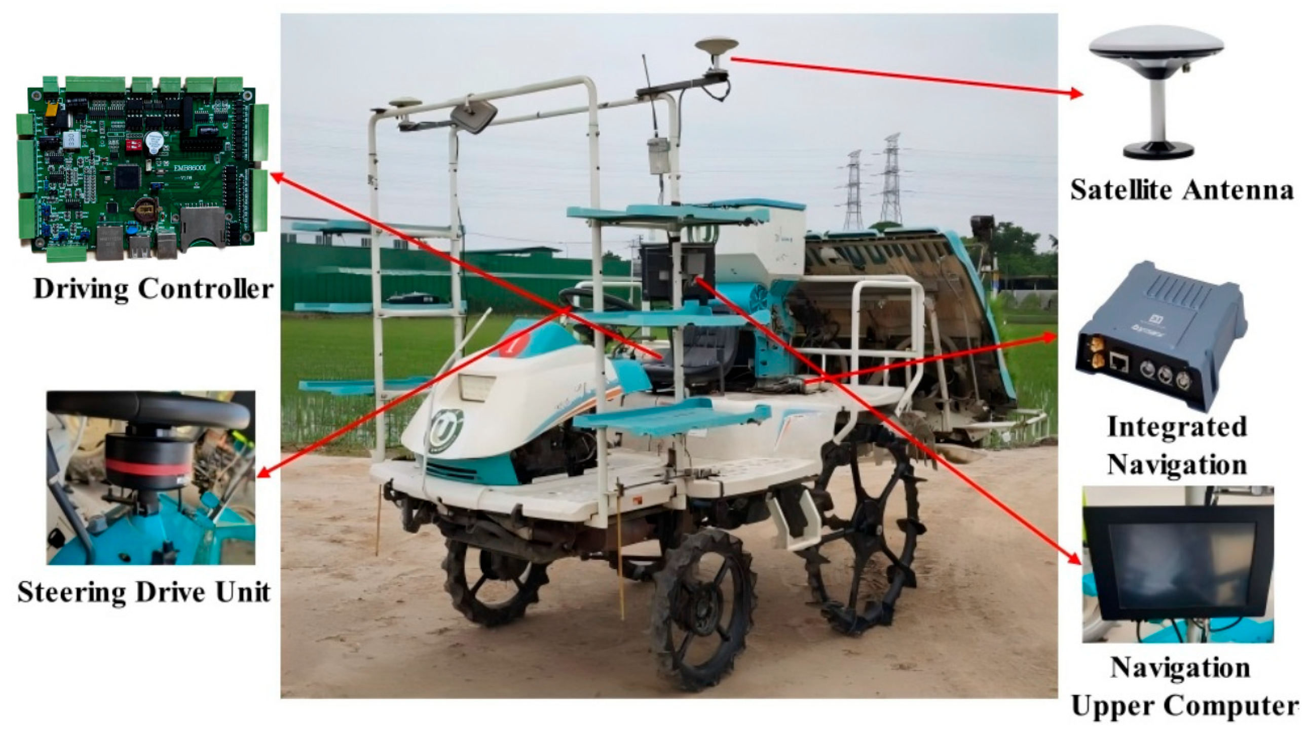
To verify the effectiveness of the designed path-tracking control method, the electronic control transformation of Jiufu 2ZG-6D (G6) rice transplanter was carried out, and an intelligent driving control system for the rice transplanter was designed. The Shanghai Lianshi AF302BD-2.5 steering drive unit is used to replace the original steering wheel. Its peak working current is 10A, and it has the characteristics of high torque and high accuracy. The Beiyun-integrated navigation system X1 has been installed. The X1-integrated navigation system is equipped with a GNSS high-precision board and a tactical IMU, supporting dual antenna RTK positioning and orientation, and deep coupling-integrated navigation algorithms. It can effectively cope with harsh environments such as satellite signal interference and loss, providing stable, continuous, and reliable high-precision position and attitude information. The navigation upper computer adopts industrial control computer as the processing core and uses navigation software independently developed based on Qt environment. It can achieve functions such as AB line navigation, whole-field navigation, and trajectory storage. And it can provide information such as vehicle position, heading, and expected path points for the control system. The independently developed automatic driving control system for rice transplanters is based on the STM32F429 as the processing core, and the overall platform is shown in Figure 5.
Figure 5.
Rice transplanter autonomous driving platform.
2.2.2. Simulation Experiment
In order to verify the effectiveness of the path-tracking control method composed of the extended LOS guidance law and the adaptive fuzzy sliding mode control law, the control method proposed in this paper was built using the Euler discretization method in Matlab 2021b environment. After multiple experiments and considering factors such as online time, maximum lateral error overshoot, and steady-state tracking error, the control parameters were optimized using gradient descent. These parameters were set to k1 = 0.15, k2 = 10, k3 = 0.02, kx = 0.5, ky = −4.6 and s(0) = 0. The expected path is y = x. The simulation step size is set to 0.01 s and the simulation duration is 40 s. The forward speed of a rice transplanter in field operations is 1 m/s, and the initial lateral error is 4 m. Through simulation experiments and comparison with the Stanley path-tracking control method, the maximum overshoot of lateral error, online time, and steady-state tracking error are used as comparison indicators.
2.2.3. Feasibility Validation Experiment
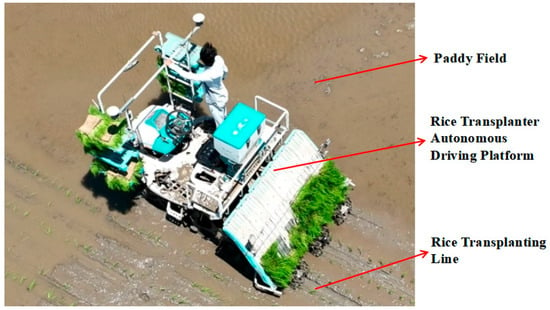
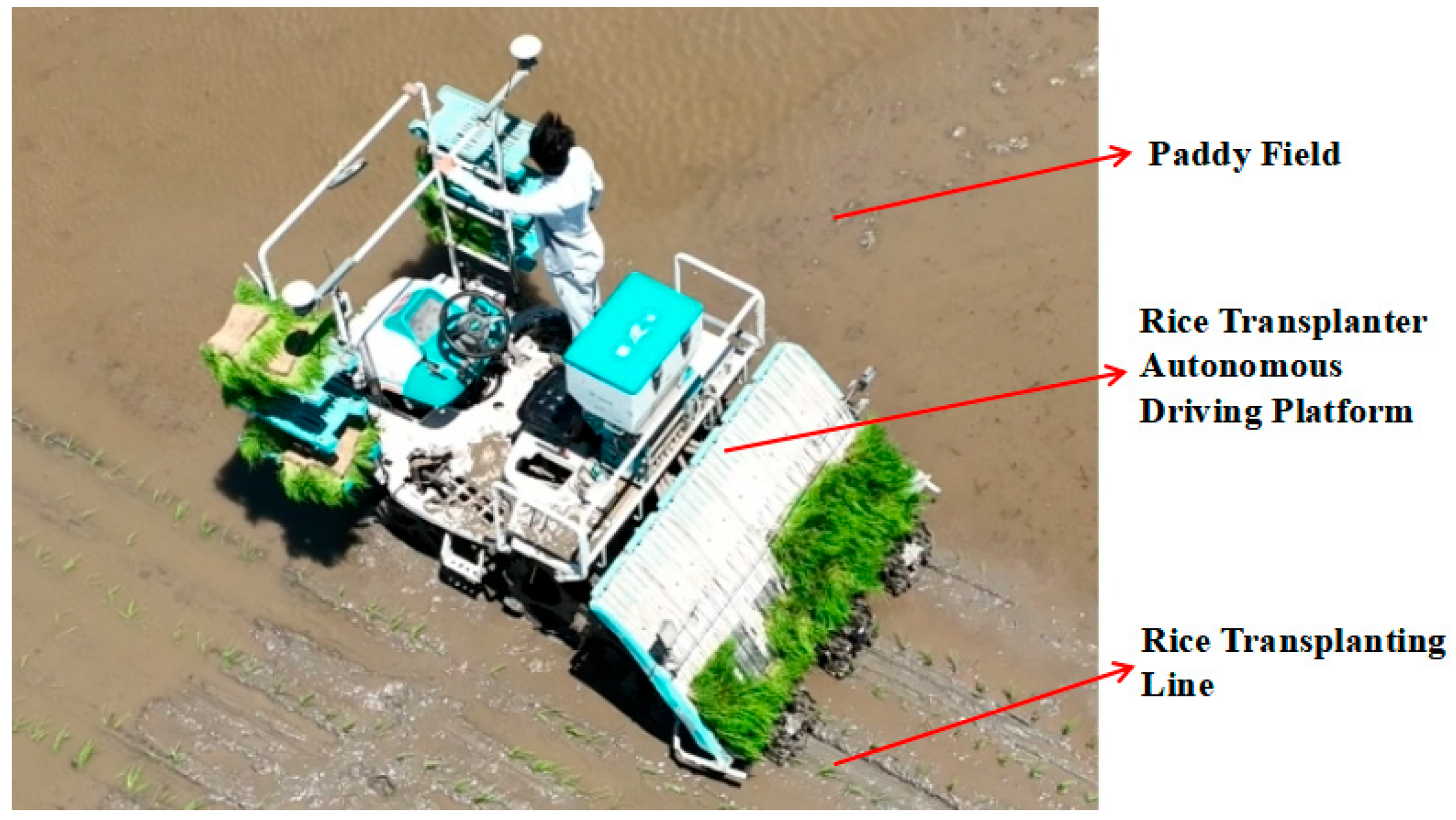
The field experiment was conducted at the Runguo Farm Drying Center in Zhenjiang New District, Zhenjiang City, Jiangsu Province. The field environment for the experiment was a pre-beaten paddy field, as shown in Figure 6. Before the experiment, a manual handheld marking device was used to locate the boundary of the field block in the experimental field, and it was recorded in the upper computer navigation software. During the experiment, the rice transplanter was manually driven to the entrance of the experimental field, and the navigation upper computer was turned on. The navigation upper computer began to send position, error, and attitude information to the automatic driving control system of the rice transplanter at a frequency of 10 Hz. The driving control system achieves lateral tracking control of the rice transplanter through the calculation of the path-tracking control method and closed-loop control of the front-wheel steering angle.
Figure 6.
Experimental scenario.
The traditional transplanting path of a rice transplanter comprises adjacent straight lines with a width of 1.8 m. The transplanting process starts from the first line and completes a U-turn to enter the next line at a distance of two widths (3.6 m) from the field head. And then, the rice transplanter continuously turns from the current line to the next line until the entire field is transplanted. In the field experiment, the path planning of the upper computer mainly focuses on rectangular transplanting areas. The expected path refers to the traditional transplanting path, which generates adjacent straight lines with a width of 1.8 m. The driving controller divides path tracking into the straight-line part and the field turn part. The straight-line part uses a path-tracking controller based on the extended LOS guidance law and the adaptive fuzzy sliding mode control law for path tracking. The field turn part automatically turns at a distance of 3.6 m from the field and enters the next line. The experimental environment of the rice transplanter is a paddy field. After completing a path-tracking experiment, the initial conditions of the paddy fields change and it is difficult to restore the original experimental conditions, which means that there are no conditions for setting up a control experiment. Therefore, the field experiment designed in this article only verifies the effectiveness of the path-tracking control method designed in this article and does not establish a control experiment.
3. Results
3.1. Result of Simulation Experiment
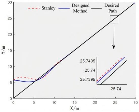
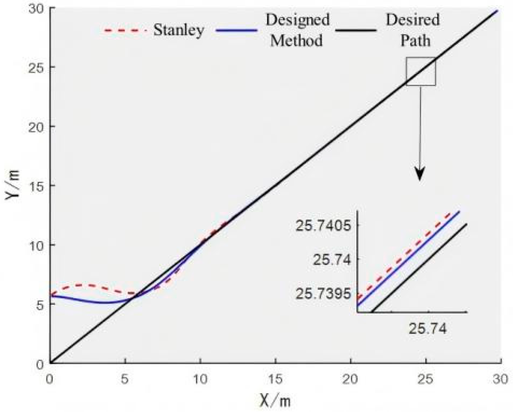
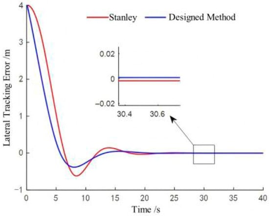
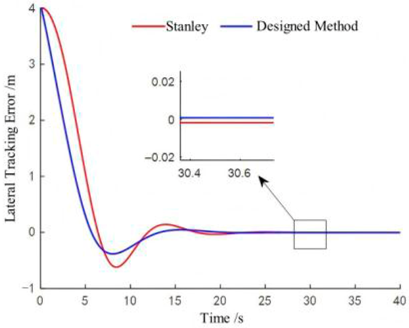
The tracking result of the expected straight path is shown in Figure 7, the lateral error during the path tracking process is shown in Figure 8, and the simulation data of the straight path is shown in Table 1. Through simulation experiments on the expected path of a straight line, it can be concluded that compared with the traditional Stanley control algorithm, the path-tracking control method proposed in this paper has a faster online speed under the same lateral error conditions, with an online time improvement of 23.9%. In addition, when the rice transplanter is quickly entering the transplanting line, the overshoot of lateral error is significantly reduced, with a decrease of 38.3%. After the path tracking enters a steady state, the steady-state tracking error of the control method proposed in this article decreased by 15.5%.
Figure 7.
Tracking trajectory of straight-line path.
Figure 8.
Lateral tracking error of straight-line path.
Table 1.
Simulation data of straight-line path tracking.
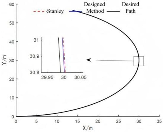
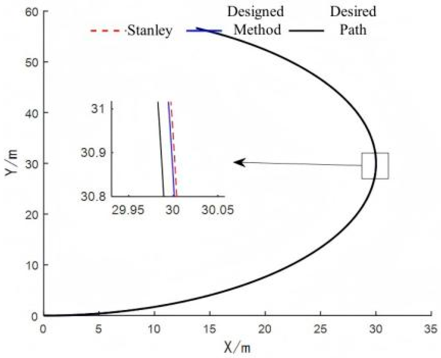
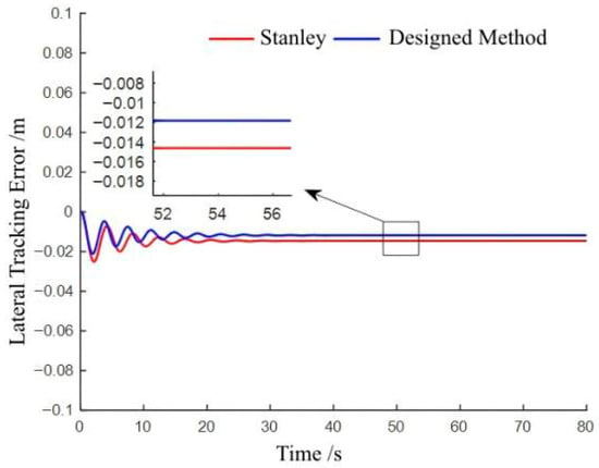
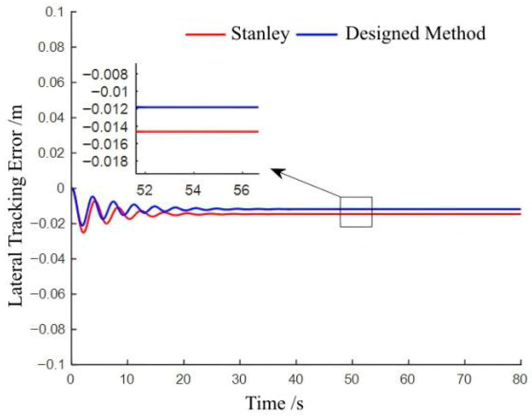
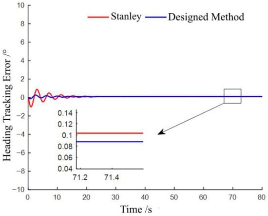
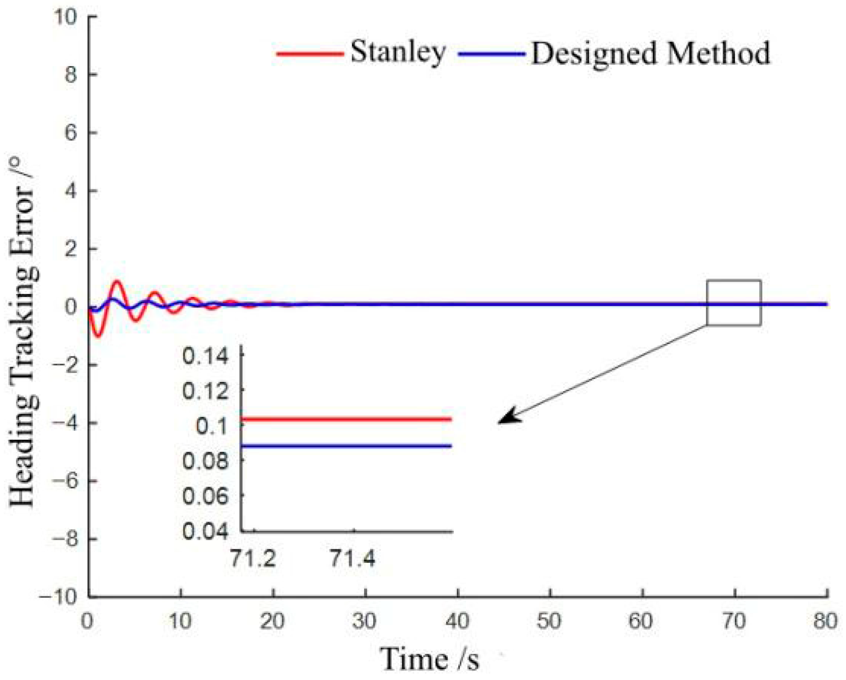
In order to fully verify the superiority of the path-tracking control method proposed in this article, the simulation comparative experiment of curved path is designed. The expected path is , , . The simulation step size is set to 0.01 s, the simulation duration is 80 s, and the forward speed of a rice transplanter in field operations is 1 m/s. The tracking results of the expected curved path are shown in Figure 9. The lateral error and heading error during the path tracking process are, respectively, shown in Figure 10 and Figure 11. The simulation data of the curved path is shown in Table 2. Through simulation comparative experiment of the expected curved path, it can be concluded that compared with the Stanley method, the method proposed in this paper exhibits superior performance in curved path tracking, with reduced steady-state tracking errors in both lateral and heading directions. The lateral steady-state tracking error is reduced by 19.2%, and the heading steady-state tracking error is reduced by 14.6%.
Figure 9.
Tracking trajectory of curve path.
Figure 10.
Lateral tracking error of curve path.
Figure 11.
Heading tracking error of curve path.
Table 2.
Simulation data of curved path tracking.
3.2. Result of Feasibility Validation Experiment
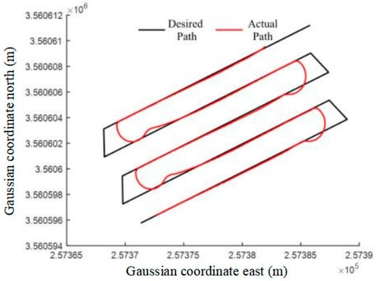
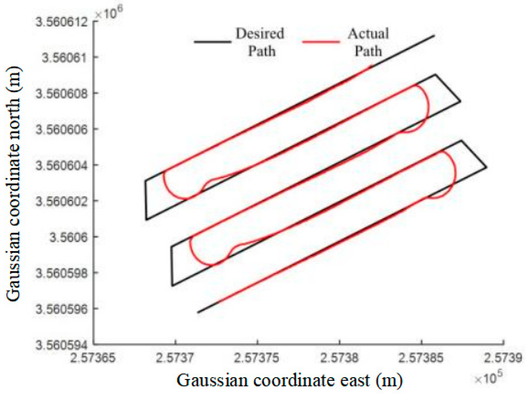
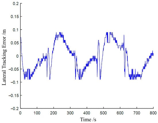
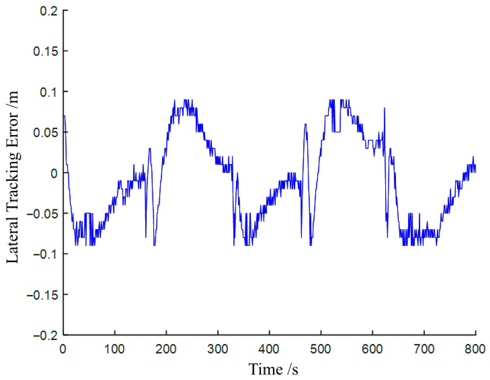
The driving trajectory of the rice transplanter under the path-tracking controller based on the extended LOS guidance law and adaptive fuzzy sliding mode control law is shown in Figure 12. The lateral error is shown in Figure 13. In the process of path tracking, the front-wheel steering angle was adjusted by the designed path-tracking controller. When the rice transplanter turned and went online, the initial lateral error was relatively large. The front-wheel steering angle was greatly adjusted to quickly reduce the lateral deviation. During the field experiment, the maximum value of the front-wheel steering angle was 42.3°. The lateral error gradually decreases with online time. And the front-wheel steering angle also decreases and gradually stabilizes. Due to uncertain disturbances and control errors, the front-wheel steering angle fluctuates between −8.5°–9.2°. The experimental result shows that the designed path-tracking controller can control the absolute value of the lateral error within 0.1 m, with an average error of 0.04 m and a variance of 0.0027 m2. The path tracking has high accuracy and strong adaptability.
Figure 12.
Field tracking trajectory of rice transplanter.
Figure 13.
Lateral tracking error in feasibility validation experiment.
4. Discussion
The path-tracking control method of the rice transplanter proposed in this article can meet the requirements of path-tracking control and unmanned driving of the entire field. The designed path-tracking control method has certain robustness and adaptability. However, considering the complexity of the paddy field environment in which the rice transplanter is transplanting, not all factors are fully considered when the path-tracking control method is designed.
The two degrees of freedom dynamic analysis are conducted on the rice transplanter. It can partially describe the motion state of the rice transplanter under complex working conditions. The effects of machine sideslips, longitudinal speed fluctuations, and environmental interference on path tracking are compensated. This is beneficial for improving the path tracking accuracy of the rice transplanter on paddy fields. But the established two-freedom dynamic models cannot fully reflect the influence of the paddy field environment on the path tracking process of the rice transplanter. This will constrain further improvement in path-tracking control effectiveness. In order to fully consider the influence of the environmental characteristics of paddy fields on the mechanical properties of rice transplanters, subsequent research should conduct dynamic analysis of multiple degrees of freedom as much as possible while meeting real-time requirements.
The extended LOS guidance method with sideslip compensation proposed in this article achieves compensation for sideslips by observing longitudinal and lateral velocities using the state observers. This method considers compensating for sideslip on the level of vehicle position changes, without analyzing environmental factors such as friction coefficient in paddy fields. Therefore, it is necessary to study the specific factors of the paddy field transplanting environment that have a direct impact on sideslips in the future in order to accurately predict and compensate for vehicle skidding and improve path tracking accuracy. Then, accurate prediction and compensation of vehicle sideslips can be made based on the corresponding influence laws, improving the accuracy of path tracking.
The path-tracking control method designed in this article was experimentally validated in paddy fields in Jiangsu and achieved good path tracking performance. Subsequently, intelligent learning methods need to be integrated into the designed control methods and tested in different paddy fields to establish a path-tracking control method for rice transplanters with self-adjusting and self-learning capabilities.
5. Conclusions
To solve the problem of lateral slip of rice transplanters in paddy fields, this paper proposes two extended state observers based on the basic principle of line-of-sight guidance method, which estimate the lateral and longitudinal velocities of rice transplanters in real time during path tracking. And an extended line-of-sight guidance method to compensate for the lateral slip angle is proposed.
In order to improve the adaptability of the path-tracking control system of the rice transplanter to unknown disturbances in complex working conditions of paddy fields, this paper designs a control law for the front wheel angle of the rice transplanter during path tracking based on the adaptive fuzzy sliding mode control method. And stability analysis is conducted on the proposed control method using the Lyapunov theory. The analysis result indicates that the control method proposed in this paper is stable.
The control method proposed in this paper is validated through the Matlab simulation software and the rice transplanter autonomous driving platform. The simulation result shows that compared with the Stanley algorithm, the proposed method reduces the maximum lateral error by 38.3% and steady-state error by 15.5% in linear path tracking, and the lateral and heading steady-state errors in curved path tracking are, respectively, reduced by 19.2% and 14.6%. The field experiment further validates the applicability of the proposed control method in paddy fields, with a stable absolute value of lateral error within 0.1 m, an average error of 0.04 m, and a variance of 0.0027 m2.
The adaptive path-tracking control algorithm designed in this article can not only meet the transplanting needs of rice transplanters to achieve precision farming in paddy field environments but also provide reference for other agricultural operation processes such as plowing, spraying, and harvesting. This research is of great significance for promoting agricultural machinery autonomous driving technology.
Author Contributions
Conceptualization, Q.S., J.S., X.L., D.D., X.W., A.W. and X.C.; resources, X.W.; methodology, Q.S., J.S., X.L., D.D., A.W. and X.C.; formal analysis, Q.S. and J.S.; writing—original draft preparation, Q.S. and J.S.; writing—review and editing, Q.S. and J.S.; supervision, X.W.; project administration, X.W.; funding acquisition, X.W. All authors have read and agreed to the published version of the manuscript.
Funding
This research was funded by the Project of Faculty of Agricultural Engineering of Jiangsu University (NGXB20240105), the High-tech Key Laboratory of Agricultural Equipment and Intelligence of Jiangsu Province (MAET202333), and the National Key Research and Development Program of China under Grant (2022ZD0115804).
Data Availability Statement
The original contributions presented in this study are included in the article. Further inquiries can be directed to the corresponding author.
Acknowledgments
We thank the editor for providing this opportunity. The authors gratefully acknowledge the reviewers for their constructive and insightful comments.
Conflicts of Interest
The authors declare no conflicts of interest.
References
- Hosseinnajad, A.; Mohajer, N.; Rokonuzzaman, M. Fixed-time convergent lateral control of autonomous vehicles based on geometric controllers. Nonlinear Dyn. 2025, 113, 18137–18157. [Google Scholar] [CrossRef] [Scilit]
- Ji, C.; Zhou, J. Current situation of navigation technologies for agricultural machinery. Nongye Jixie Xuebao/Trans. Chin. Soc. Agric. Mach. 2014, 45, 44–54. [Google Scholar] [CrossRef]
- Jin, Y.C.; Liu, J.Z.; Xu, Z.J.; Yuan, S.Q.; Li, P.P.; Wang, J.Z. Development status and trend of agricultural robot technology. Int. J. Agric. Biol. Eng. 2021, 14, 1–19. [Google Scholar] [CrossRef] [Scilit]
- Liu, C.; Lin, H.; Li, Y.; Gong, L.; Miao, Z. Analysis on Status and Development Trend of Intelligent Control Technology for Agricultural Equipment. Nongye Jixie Xuebao/Trans. Chin. Soc. Agric. Mach. 2020, 51, 1–18. [Google Scholar] [CrossRef]
- Nagasaka, Y.; Umeda, N.; Kanetai, Y.; Taniwaki, K.; Sasaki, Y. Autonomous guidance for rice transplanting using global positioning and gyroscopes. Comput. Electron. Agric. 2004, 43, 223–234. [Google Scholar] [CrossRef]
- Yin, X.; Du, J.; Noguchi, N.; Yang, T.X.; Jin, C.Q. Development of autonomous navigation system for rice transplanter. Int. J. Agric. Biol. Eng. 2018, 11, 89–94. [Google Scholar] [CrossRef] [Scilit]
- Yun, C.H.; Kim, H.J.; Jeon, C.W.; Gang, M.S. Quick turn headland-turning control strategy for autonomous rice transplanters. Comput. Electron. Agric. 2025, 239, 110864. [Google Scholar] [CrossRef] [Scilit]
- Zhang, W.P.; Lu, M.; Wei, L.X.; Yang, S.J.; Wang, L.X.H.; Ma, P.; Lin, X.X.; Hu, A.R.; Liu, S.X.; Fu, S.H. Design and Research of High-Speed Synchronous Membrane-Covering Device for Rice Membrane-Covering Transplanter Based on PSO-Fuzzy PID. Agronomy 2025, 15, 1962. [Google Scholar] [CrossRef] [Scilit]
- Zhong, Z.D.; Yao, Y.F.; Zhu, J.Y.; Liu, Y.F.; Du, J.; Yin, X. Automation of Rice Transplanter Using Agricultural Navigation. Agriculture 2025, 15, 1125. [Google Scholar] [CrossRef] [Scilit]
- Jing, Y.; Liu, G.; Jin, Z. Adaptive Guidance Control Method with Sideslip Estimation for Land Leveler Pulling by Tractor. Nongye Jixie Xuebao/Trans. Chin. Soc. Agric. Mach. 2020, 51, 26–33. [Google Scholar] [CrossRef]
- Han, X.Z.; Kim, H.J.; Kim, J.Y.; Yi, S.Y.; Moon, H.C.; Kim, J.H.; Kim, Y.J. Path-tracking simulation and field tests for an auto-guidance tillage tractor for a paddy field. Comput. Electron. Agric. 2015, 112, 161–171. [Google Scholar] [CrossRef] [Scilit]
- Lu, E.; Ma, Z.; Li, Y.M.; Xu, L.Z.; Tang, Z. Adaptive backstepping control of tracked robot running trajectory based on real-time slip parameter estimation. Int. J. Agric. Biol. Eng. 2020, 13, 178–187. [Google Scholar] [CrossRef] [Scilit]
- Li, T.; Hu, J.; Gao, L.; Liu, X.; Bai, X. Agricultural machine path tracking method based on fuzzy adaptive pure pursuit model. Nongye Jixie Xuebao/Trans. Chin. Soc. Agric. Mach. 2013, 44, 205–210. [Google Scholar] [CrossRef]
- Qu, J.W.; Zhang, Z.; Qin, Z.Y.; Guo, K.Q.; Li, D. Applications of Autonomous Navigation Technologies for Unmanned Agricultural Tractors: A Review. Machines 2024, 12, 218. [Google Scholar] [CrossRef] [Scilit]
- Yin, X.; Wang, Y.X.; Chen, Y.L.; Jin, C.Q.; Du, J. Development of autonomous navigation controller for agricultural vehicles. Int. J. Agric. Biol. Eng. 2020, 13, 70–76. [Google Scholar] [CrossRef] [Scilit]
- Höffmann, M.; Patel, S.; Büskens, C. Optimal guidance track generation for precision agriculture: A review of coverage path planning techniques. J. Field Robot. 2024, 41, 823–844. [Google Scholar] [CrossRef] [Scilit]
- Luo, X.; Hu, L.; Liao, J.; Zhou, Z.; He, J.; Ma, X.; Zhang, W.; Zeng, S. Exploration and Practice of Unmanned Smart Rice Farms. Nongye Jixie Xuebao/Trans. Chin. Soc. Agric. Mach. 2025, 56, 277–290. [Google Scholar] [CrossRef]
- Luo, X.; Zhang, Z.; Zhao, Z.; Chen, B.; Hu, L.; Wu, X. Design of DGPS navigation control system for Dongfanghong X-804 tractor. Nongye Gongcheng Xuebao/Trans. Chin. Soc. Agric. Eng. 2009, 25, 139–145. [Google Scholar] [CrossRef]
- Tang, X.; Tao, J.; Li, Z.; Li, Y.; Liu, C. Fuzzy Control Optimization Method for Stability of Path Tracking System of Automatic Transplanter. Nongye Jixie Xuebao/Trans. Chin. Soc. Agric. Mach. 2018, 49, 29–34. [Google Scholar] [CrossRef]
- Chi, R.; Xiong, Z.; Jiang, L.; Ma, Y.; Huang, X.; Zhu, X. Path Tracking Control Algorithm of Transplanter Based on Model Prediction. Nongye Jixie Xuebao/Trans. Chin. Soc. Agric. Mach. 2022, 53, 22–30, 99. [Google Scholar] [CrossRef]
- Lin, H.; Li, Y.; Yuan, Z.; Wu, T.; Liu, C. Sliding Mode Anti-interference Path Tracking Method for Autonomous Operation of Paddy Field Plant Protection Machine. Nongye Jixie Xuebao/Trans. Chin. Soc. Agric. Mach. 2021, 52, 383–388. [Google Scholar] [CrossRef]
- Ding, C.; Ding, S.H.; Wei, X.H.; Mei, K.Q. Output feedback sliding mode control for path-tracking of autonomous agricultural vehicles. Nonlinear Dyn. 2022, 110, 2429–2445. [Google Scholar] [CrossRef] [Scilit]
- Tiep, D.K.; Lee, K.; Im, D.Y.; Kwak, B.; Ryoo, Y.J. Design of Fuzzy-PID Controller for Path Tracking of Mobile Robot with Differential Drive. Int. J. Fuzzy Log. Intell. Syst. 2018, 18, 220–228. [Google Scholar] [CrossRef] [Scilit]
- AbdElmoniem, A.; Osama, A.; Abdelaziz, M.; Maged, S.A. A path-tracking algorithm using predictive Stanley lateral controller. Int. J. Adv. Robot. Syst. 2020, 17, 1729881420974852. [Google Scholar] [CrossRef] [Scilit]
- An, G.S.; Zhong, Z.D.; Yang, S.; Yang, L.L.; Jin, C.Q.; Du, J.; Yin, X. EASS: An automatic steering system for agricultural wheeled vehicles using fuzzy control. Comput. Electron. Agric. 2024, 217, 108544. [Google Scholar] [CrossRef] [Scilit]
- Ji, X.; Wei, X.H.; Wang, A.Z.; Cui, B.B.; Song, Q. A novel composite adaptive terminal sliding mode controller for farm vehicles lateral path tracking control. Nonlinear Dyn. 2022, 110, 2415–2428. [Google Scholar] [CrossRef] [Scilit]
- Sun, J.L.; Wang, Z.; Ding, S.H.; Xia, J.; Xing, G.Y. Adaptive disturbance observer-based fixed time nonsingular terminal sliding mode control for path-tracking of unmanned agricultural tractors. Biosyst. Eng. 2024, 246, 96–109. [Google Scholar] [CrossRef] [Scilit]
- He, J.; Zeng, H.; Li, M.; He, J.; Mo, J.; Wang, P.; Zhao, R. Improved Pure Pursuit Path Tracking Control Method for Automatic Navigation Tractor Based on Drive Wheel Lateral Deviation Compensation. Trans. Chin. Soc. Agric. Mach. 2025, 56, 28–37. [Google Scholar] [CrossRef]
- Cheng, J.; Zhang, B.L.; Zhang, C.B.; Zhang, Y.Y.; Shen, G. A model-free adaptive predictive path-tracking controller with PID terms for tractors. Biosyst. Eng. 2024, 242, 38–49. [Google Scholar] [CrossRef] [Scilit]
- Liu, Q.; Wang, Z.; Zhao, L. Vehicle tracking optimization based on adaptive LOS guidance and MPC control. J. Harbin Inst. Technol. 2022, 54, 96–104. [Google Scholar] [CrossRef]
- Breivik, M.; Fossen, T.I. Path following of straight lines and circles for marine surface vessels. IFAC Proc. Vol. 2004, 37, 65–70. [Google Scholar] [CrossRef] [Scilit]
- Wang, N.; Sun, Z.; Su, S.F.; Wang, Y.Y. Fuzzy Uncertainty Observer-Based Path-Following Control of Underactuated Marine Vehicles with Unmodeled Dynamics and Disturbances. Int. J. Fuzzy Syst. 2018, 20, 2593–2604. [Google Scholar] [CrossRef] [Scilit]
- Xiang, X.B.; Lapierre, L.; Jouvencel, B. Smooth transition of AUV motion control: From fully-actuated to under-actuated configuration. Robot. Auton. Syst. 2015, 67, 14–22. [Google Scholar] [CrossRef] [Scilit]

Disclaimer/Publisher’s Note: The statements, opinions and data contained in all publications are solely those of the individual author(s) and contributor(s) and not of MDPI and/or the editor(s). MDPI and/or the editor(s) disclaim responsibility for any injury to people or property resulting from any ideas, methods, instructions or products referred to in the content. |
© 2026 by the authors. Licensee MDPI, Basel, Switzerland. This article is an open access article distributed under the terms and conditions of the Creative Commons Attribution (CC BY) license.