


Abstract
La-doped CeO2 (LDC) coatings are promising thermal barrier coating candidates for nickel-based superalloys, but systematic studies on their thermal shock resistance, particularly for coatings fabricated by electron beam physical vapor deposition (EB-PVD), remain limited. In this work, LDC coatings with different La doping levels (0, 20%, and 40 at.%) were deposited onto a nickel-based alloy substrate by EB-PVD, and their thermal shock resistance was evaluated by thermal cycling between room temperature and 1000 °C. All coatings survived 480 cycles without spallation, and the 40% LDC coating exhibited the least surface damage and the best thermal shock resistance. The growth of the thermally grown oxide (TGO) layer followed two-stage parabolic kinetics before and after microcrack initiation. The surface hardness of the doped coatings increased rapidly during the first 10 cycles, remained stable between 10 and 120 cycles, and then increased again after 120 cycles, whereas that of pure CeO2 decreased after 60 cycles. The cracking mechanisms were governed by residual stress, coating densification, and TGO growth. Atomic diffusion promoted crack healing, but the healing effect was strongly limited by crack width: once the crack width exceeded a critical value, the diffusion distance became kinetically prohibitive, resulting in only marginal morphological changes at the crack edges rather than complete healing.
1. Introduction
Nickel-based superalloys have long been the material of choice for hot-section components in aero-engines and for high-temperature structural parts in aerospace systems, owing to their excellent high-temperature strength, oxidation resistance, and resistance to hot-gas corrosion [1,2,3]. With the continuing increase in flight Mach number of hypersonic vehicles, however, the aerodynamic heating environment faced by thermal protection systems has become increasingly severe. Gas temperatures in the combustor walls and exhaust nozzles can reach 1700 K or higher, whereas the upper limit for long-term reliable service of conventional nickel-based superalloys is typically below 1300 K [4,5]. Consequently, even when a nickel-based alloy is used as the structural material of a metallic thermal protection system, an additional thermal protection layer must be applied to its surface in order to reduce the actual temperature experienced by the alloy and to suppress high-temperature oxidation; otherwise, structural integrity and service life cannot be guaranteed.
In this context, thermal barrier coatings (TBCs) have been introduced into the design of metallic thermal protection systems for hypersonic vehicles. It should be noted that the functional role of TBCs in hypersonic applications differs to some extent from that of TBCs on turbine blades in conventional aero-engines. In the conventional engine environment, the primary function of a TBC is to reduce the temperature of the blade alloy substrate, thereby retarding creep damage and extending blade life [6,7]. During high-temperature service, a thermally grown oxide (TGO) layer, predominantly α-Al2O3 or Cr2O3, forms at the interface between the bond coat and the ceramic topcoat. Although the TGO layer offers oxidation protection, its continued growth during thermal cycling generates significant thermal mismatch stresses at the TGO/ceramic interface, which is a primary cause of coating spallation [8,9]. However, in the metallic thermal protection structures of hypersonic vehicles, by contrast, the coating simultaneously fulfils two coupled functions. First, the low thermal conductivity of the ceramic layer establishes a temperature gradient under aerodynamic heating, so that the temperature of the metallic structure is maintained within an acceptable range. Second, the coating acts as an environmental barrier that impedes the inward diffusion of oxygen into the alloy substrate, suppressing high-temperature oxidation that would otherwise cause wall thinning and degradation of mechanical properties. These two functions impose requirements on the thermophysical properties and high-temperature chemical stability of the coating material that are not identical to those for engine TBCs. In this paper, the TGO forms directly at the coating/substrate interface in a bond-coat-free architecture, and its evolution is worth investigating.
Among candidate ceramic materials, CeO2-based materials have attracted attention because of their relatively high thermal expansion coefficient (TEC) and low thermal conductivity [10,11,12,13]. The TEC of pure CeO2 is approximately 11.5–12.3 × 10⁻⁶ K−1 in the temperature range of 50–1000 °C, which is close to that of nickel-based alloys and therefore helps to reduce the thermal mismatch stress at the ceramic/metal interface during thermal cycling. However, pure CeO2 suffers from a pronounced tendency toward reduction from Ce4+ to Ce3+ at elevated temperatures, accompanied by oxygen release and lattice expansion, and its sintering resistance is insufficient: under prolonged high-temperature exposure it undergoes grain growth and densification, which degrades the strain tolerance of the coating [14,15,16]. These intrinsic drawbacks limit the reliability of pure CeO2 as a thermal protection coating under long-term high-temperature service conditions.
To overcome these limitations, various strategies for modifying CeO2 have been explored. Among them, doping with trivalent rare-earth ions has been widely adopted [10]. Doping CeO2 with trivalent cations (such as La3+, Gd3+, Sm3+, and Y3+) at Ce4+ sites introduces compensating oxygen vacancies to maintain charge neutrality, which simultaneously improves phase stability and modifies transport properties [17]. Among these dopants, La3+ is particularly attractive not merely because of its large ionic radius, but because the size mismatch itself serves a specific defect-chemical function. The ionic radius of La3+ (1.16 Å) is substantially larger than that of Ce4+ (0.97 Å) [18]. When La3+ substitutes for Ce4+, the charge imbalance is compensated by oxygen vacancy formation, and the large size mismatch simultaneously reduces the oxygen vacancy formation energy [19]. Positron annihilation and XPS studies comparing La3+ with smaller trivalent dopants have shown that La-doped ceria exhibits a higher oxygen vacancy concentration and a higher Ce3+/Ce4+ ratio than Y3+- or Eu3+-doped counterparts. Moreover, atomistic calculations indicate that large dopants such as La3+ prefer to bind oxygen vacancies at second-neighbour sites rather than first-neighbour sites, which weakens the trapping of vacancies in stable defect clusters and preserves a more mobile vacancy population. This distinction matters for the present work because the oxygen transport rate through the coating directly controls TGO growth, which is a primary determinant of thermal shock lifetime.
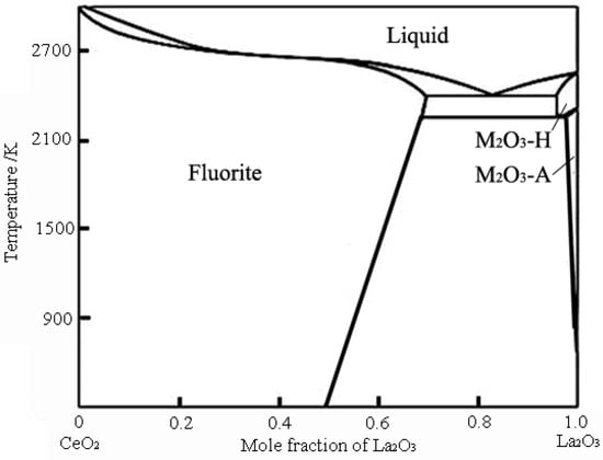
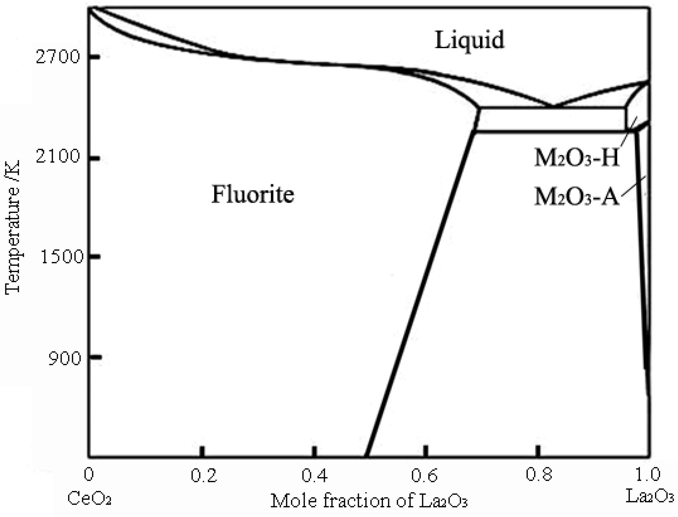
It is well established from the CeO2-La2O3 phase diagram that when the La mole fraction is below 50%, La-doped CeO2 (LDC) retains the cubic fluorite structure without phase transformation, ensuring structural integrity across the intended service temperature range [20], as shown in Figure 1. Studies have shown that La doping increases the lattice parameter of CeO2 while maintaining the fluorite structure [21]. Importantly, the TEC of LDC coatings in the range of 300–1200 °C is approximately 11.8–12.9 × 10⁻⁶ K−1 [13], which remains closely matched to that of nickel-based superalloys, thus preserving thermal expansion compatibility while achieving superior high-temperature stability. Moreover, La doping has been reported to significantly improve the sintering resistance of CeO2 [22]. This enhanced sintering resistance means that LDC coatings are less prone to densification-induced stress accumulation during prolonged high-temperature exposure, which is beneficial for extending thermal cycling lifetime.
Figure 1.
Phase diagram of CeO2-La2O3 [20].
Given these favorable attributes, LDC coatings have been considered as ceramic topcoat candidates for bond-coat-free metallic thermal-protection systems, where the coating must remain thermochemically stable on a chromia-forming alloy and accommodate thermal mismatch without a compliant bond coat. It should be emphasized that the present work does not aim to replace YSZ in conventional turbine-blade TBCs with LDC. Rather, the objective is to investigate the composition–microstructure–mechanical-state relationships that govern the durability of EB-PVD columnar LDC coatings in this specific bond-coat-free configuration. Previous studies on LDC have been performed largely on powders, bulks, or plasma-sprayed coatings, and therefore could not resolve (i) whether La doping suppresses TGO growth in the crack-free stage and to what extent, (ii) how the hardness of columnar EB-PVD LDC evolves beyond the initial densification stage, and (iii) whether the large La3+ ion produces a residual stress state beneficial or detrimental to thermal shock resistance. The present work addresses these three questions by depositing LDC coatings with different La atomic concentrations (0, 20%, and 40% La in the evaporation materials) onto Haynes 214 substrates using EB-PVD, and by systematically evaluating their thermal shock resistance in terms of surface damage area fraction, TGO growth kinetics, and hardness evolution.
2. Materials and Methods
In this study, commercially available CeO2 and La2O3 powders (Aladdin, Shanghai, China, 99.9% purity, <2 μm) were weighed according to nominal La/(La + Ce) atomic ratios of 0, 20%, and 40%. The powder mixtures were homogenized by wet ball milling in a QM-3SP2 planetary ball mill (Nanjing Nanda Instrument Co., Ltd., Nanjing, China) using a 250 mL alumina jar. Zirconia balls with three diameters (ϕ5, ϕ8, and ϕ20 mm) were used as the milling media in a mass ratio of 40%:40%:20%. Anhydrous ethanol was used as the milling medium, and sodium dodecylbenzenesulfonate was added as a surfactant to improve powder dispersion. The mass ratio of milling balls:oxide powders: anhydrous ethanol was fixed at 8:1:1. The mixture was homogenized at 200 rpm for 24 h. After milling, the slurry was dried in an oven at 50–60 °C, cold-pressed into compacts of 69 mm diameter under 30 MPa, and sintered at 1300 °C in air for 2 h to densify and strengthen the cold-pressed compacts into evaporation targets.
The corresponding coatings were designated as pure CeO2, 20% LDC, and 40% LDC, respectively. All coatings were deposited on Haynes 214 nickel-based alloy substrates using the EB-PVD technique with identical process parameters: deposition current was 0.25 A, deposition power was 5 kW, substrate temperature was 900 °C using graphite resistance heating, target-to-substrate distance was 160 mm, and deposition time was 360 s. During the entire deposition process, the chamber vacuum (about 3 m3) was maintained at approximately 2 × 10⁻³ Pa. Table 1 lists the process parameters for the EB-PVD deposition of LDC coatings. Except for the target composition, all deposition conditions were kept identical.
Table 1.
Parameters of LDC deposition by EB-PVD.
The microstructure of the raw powders, the surface and cross-sectional morphologies of the coatings, and the interfacial bonding between the coating and the substrate were observed using a Hitachi SU1000 cold-field emission scanning electron microscope (SEM) (Hitachi High-Technologies, Tokyo, Japan) and a Fei Sirion 400 thermal-field emission SEM (FEI, Hillsboro, OR, USA). Because the LDC coatings have poor electrical conductivity, the sample surfaces were sputtered with gold prior to observation. Energy-dispersive X-ray spectroscopy (EDS) attached to the SEM was used for point and line scans on cross-sections, with an accelerating voltage of 20 kV. Wide-angle XRD patterns were collected for phase identification and crystallite size calculation using an XRD diffractometer with Cu Kα radiation (Panalytical, Almelo, Overijssel, The Netherlands). The actual La/(La + Ce) atomic ratios of the as-deposited coatings were determined by X-ray fluorescence (XRF) spectrometry (PANalytical Axios mAX, Panalytical, Almelo, Overijssel, The Netherlands) equipped with a Rh target X-ray tube. The measurements were performed at an accelerating voltage of 40 kV and a current of 75 mA.
The thermal cycling test was carried out as follows: each specimen was heated in a muffle furnace at 1000 °C for 10 min, then removed and cooled to room temperature by a forced air stream over 3 min, after which it was returned to the furnace for the next cycle. This procedure was repeated until the test was terminated. Because the back side of the specimen was not coated, the metallic substrate underwent severe oxidation during prolonged exposure to the high-temperature air atmosphere. As the oxide layer thickened, the stresses on the two sides of the Ni-based alloy substrate became unbalanced. After 480 thermal cycles, although the coating remained intact without any spallation, noticeable bending deformation had developed in the substrate. The thermal shock test was therefore terminated at 480 cycles.
It should be noted that the termination at 480 cycles reflects the physical limit of the uncoated substrate rather than the life limit of the ceramic coating; the 480-cycle result therefore represents a lower bound on the thermal shock durability of the LDC coatings under this deliberately harsh, bond-coat-free architecture.
The thermal cycling experiments were designed to resolve the three questions posed in the Introduction: TGO thickness was measured to quantify La-dependent oxygen transport, hardness and modulus were tracked to distinguish densification from doping-induced stress effects, and residual stress was measured on as-deposited coatings to establish the initial mechanical state.
The microhardness of the as-deposited coatings and of coating surfaces after thermal shock testing was measured using a Laihua HV-1000 microhardness tester (Laizhou Laihua Testing Instrument Factory, Laizhou, China) with a diamond indenter, a load of 200 g, and a dwell time of 10 s. Seven points were tested for each sample. The average of the two diagonals of each indentation was used to calculate the hardness value, and the average of the seven points was taken as the microhardness of the coating.
Residual stress in the coatings was analyzed using a PANalytical X’Pert Pro MRD X-ray diffractometer (XRD) (Panalytical, Almelo, Overijssel, The Netherlands). The shift in the (622) diffraction peak of LDC coatings near 141.5° was measured, and the lattice constant was calculated from the peak shift. Using the elastic moduli obtained from nanoindentation and a Poisson’s ratio of 0.25, the internal stress state was calculated using Equations (1)–(4).
Let , , then
Further rearrangement gives:
Let , , then,
where K and K′ are crystallographic constants of the material; M is the slope of the interplanar spacing d versus sin2ψ; M′ is the slope of the diffraction angle 2θ versus sin2ψ; E is the elastic modulus; and ν is Poisson’s ratio. Thus, the residual stress in the material can be obtained simply from the slope of d versus sin2ψ or the slope of 2θ versus sin2ψ.
The elastic modulus of the as-deposited coatings was measured using a nanoindenter (Agilent G200, Agilent Technologies, Santa Clara, CA, USA) equipped with a Berkovich diamond tip. The measurements were performed under a maximum load of 10 mN with a loading/unloading rate of 2 mN/s. A thermal drift correction was applied before each indent measurement. For each coating, at least twelve indents were made to obtain statistically reliable results. The elastic modulus was calculated from the unloading curve using the Oliver–Pharr method.
The failure mechanism of the coatings was analyzed by examining the surface, cross-sectional microstructures, the TGO thickness and microcracks evolution during thermal cycling.
For each experimental condition, three parallel specimens were tested to ensure statistical reliability. The results are reported as mean ± standard deviation.
3. Results
3.1. As-Deposited Morphology and Phase Analysis
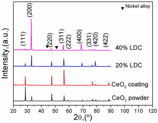
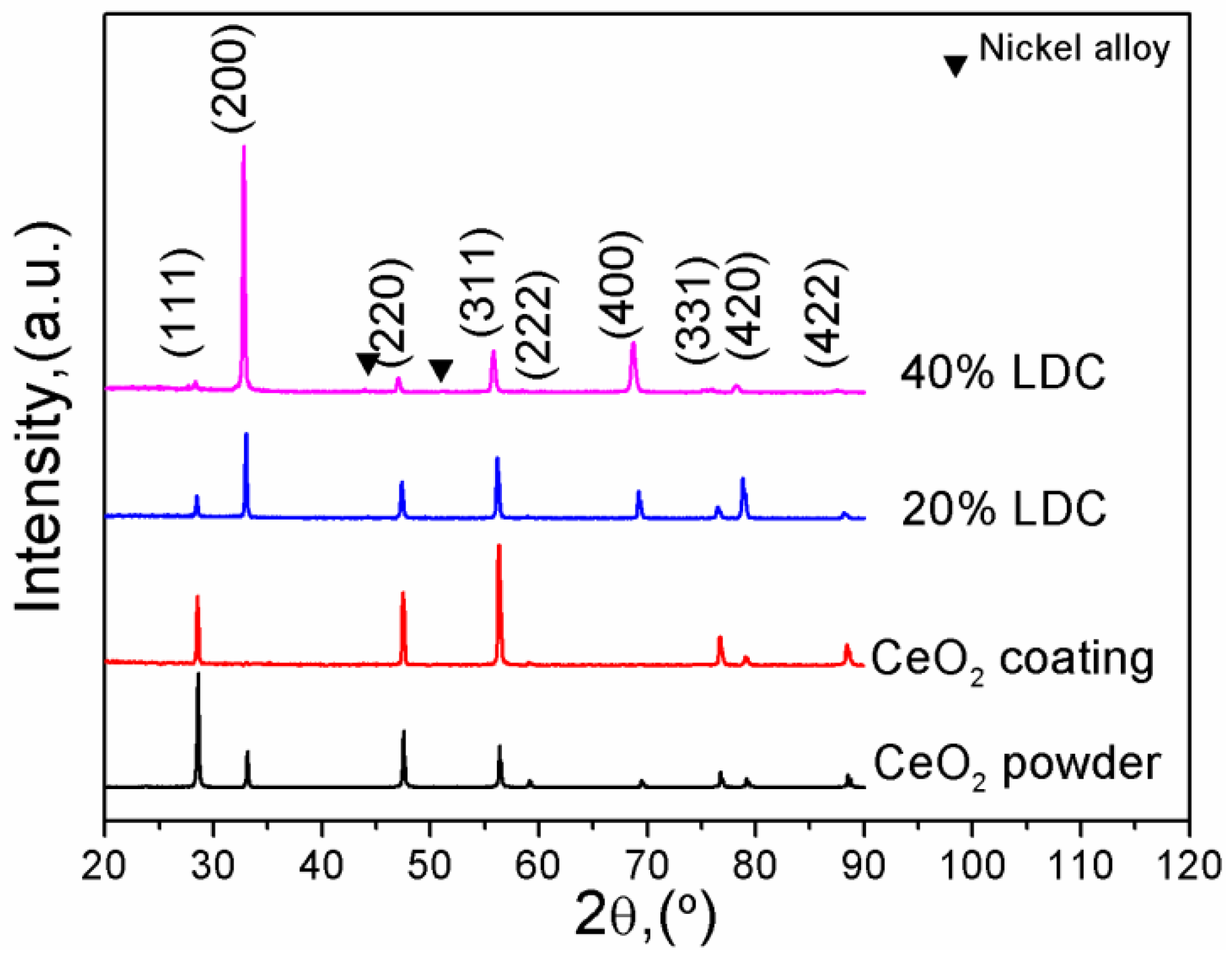
Figure 2 shows the XRD patterns of La-CeO2 coatings and CeO2 raw material. All samples display a defect fluorite structure, only weak diffraction peaks are observed at 2θ ≈ 44° and 51° in the XRD pattern of the 40% LDC, corresponding to the (111) and (200) reflections of the Ni-based alloy substrate (JCPDS No. 04-0850). These substrate peaks are not related to the preferred orientation of the LDC coating. The crystallite sizes were evaluated using the Scherrer formula based on the data. The lattice constants were calculated to be 0.5411 nm for pure CeO2, 0.5423 nm for 20% LDC (an increase of 0.26%), and 0.5459 nm for 40% LDC (an increase of 0.88%), which indicates that La has been doped into the CeO2 lattice. This assignment is supported by two independent features: the systematic lattice expansion with increasing La content, and the retention of a single-phase fluorite structure without detectable La2O3 reflections. With the increase in La content in the coating, the preferred orientation of the coating changed from the (311) plane to the (100) orientation. This is because the ionic radius of La3+ (0.110 nm) is much larger than that of Ce4+ (0.097 nm). Therefore, when La3+ substitutes for Ce4+ in the CeO2 lattice, the lattice expands and lattice distortion occurs. La3+ spontaneously prefers to substitute for Ce4+ ions at the grain boundaries. For La-CeO2 coatings grown in the form of columnar crystals, the side surfaces of the columnar crystals have the highest energy; thus, La3+ tends to substitute for Ce4+ on the side surfaces, further promoting the preferred orientation growth of the coating. The average crystallite sizes of the coatings are 75 nm (pure CeO2), 70 nm (20% LDC) and 49 nm (40% LDC). A clear trend of enhanced grain refinement is observed in the as-deposited coatings with increasing La doping level.
Figure 2.
XRD patterns of LDC coatings and CeO2 raw material.
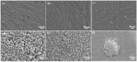
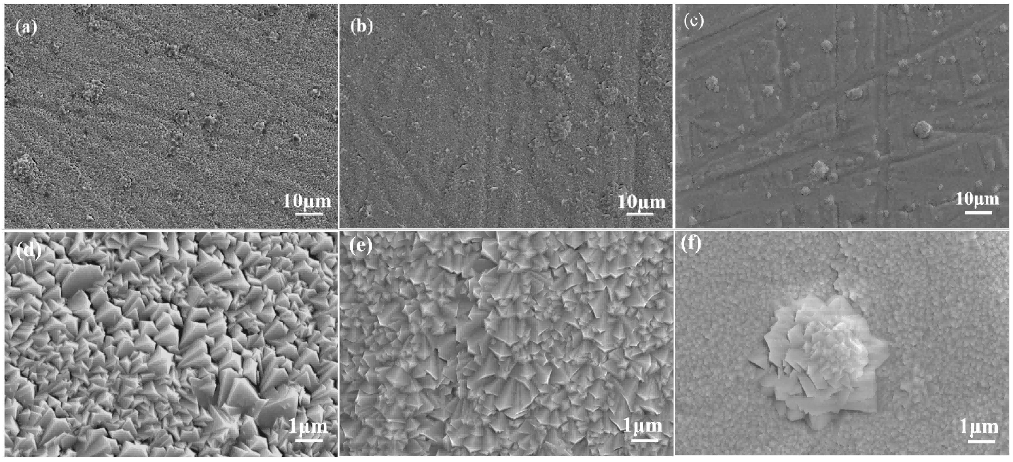
Figure 3 shows surface morphology photographs of La-CeO2 coatings with different La doping concentrations. All coatings exhibit similarly dense and smooth surfaces with minor cauliflower-like clusters, indicating identical growth kinetics under the same deposition conditions.
Figure 3.
Surface morphology of LDC coatings. (a,d) Pure CeO2 coating; (b,e) 20% LDC; (c,f) 40% LDC.
The actual La/(La + Ce) atomic ratios of the as-deposited coatings were determined by X-ray fluorescence (XRF) analysis, and the results are listed in Table 2. The measured La contents are consistently lower than the nominal target values—for example, 16.7 at.% for the nominally 40% LDC coating. The XRF data reflect the composition of the deposited coating rather than that of the target; the lower La content in the coating is attributed to the lower saturation vapor pressure of La2O3 relative to CeO2 during EB-PVD.
Table 2.
The compositions of LDC targets and coatings.
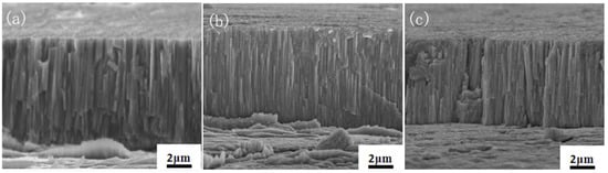
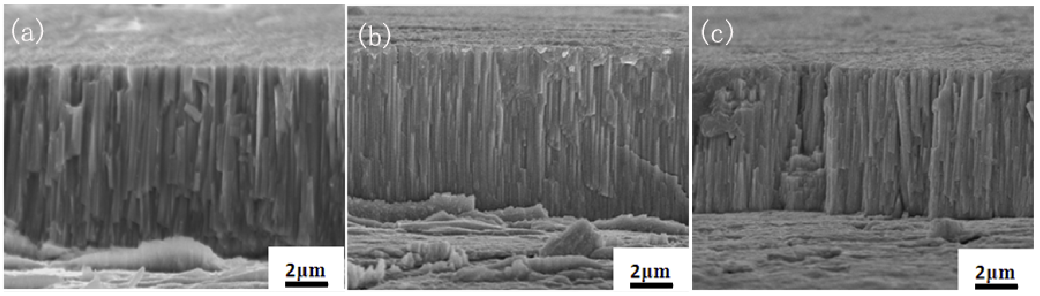
Figure 4 presents the cross-sectional morphologies of LDC coatings with varying La doping concentrations. In all examined cross-sections, good bonding between the coating and the substrate is observed, with no visible gaps or pores at the interface regions. The coatings exhibit vertical, square-shaped columnar grains that were tightly packed, confirming their high density. The coating thicknesses measured from the cross-sectional images are 9.1 ± 0.6 μm for pure CeO2, 8.1 ± 0.5 μm for 20% LDC and 6.9 ± 0.4 μm for 40% LDC. Under identical substrate temperature and deposition power, both the coating growth rate and the resulting thickness decrease with increasing La doping concentration. This thickness reduction is attributed to two factors: the lower saturation vapor pressure of La2O3 relative to CeO2 (as confirmed by XRF analysis in Table 2), and the increased surface energy arising from La-induced lattice expansion, which reduces the sticking coefficient of incoming vapor species.
Figure 4.
Cross-section morphology of LDC coatings. (a) Pure CeO2 coating; (b) 20% LDC; (c) 40% LDC.
3.2. Microstructural Evolution of La-CeO2 Coatings
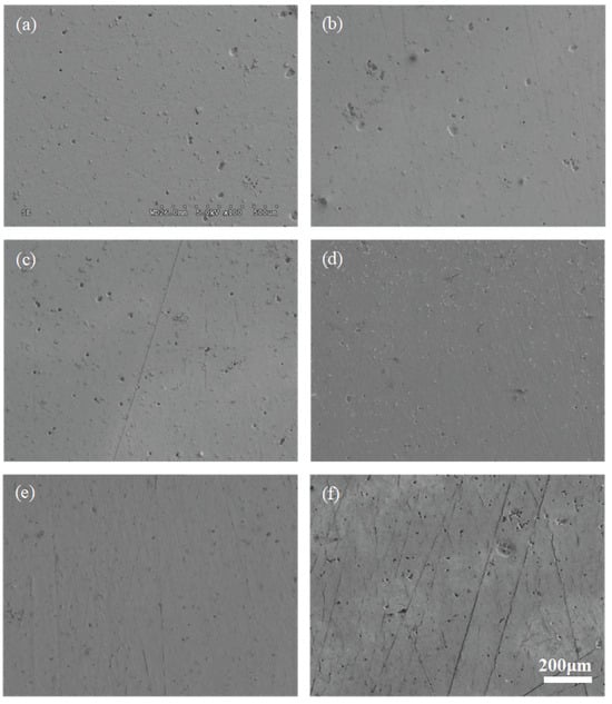
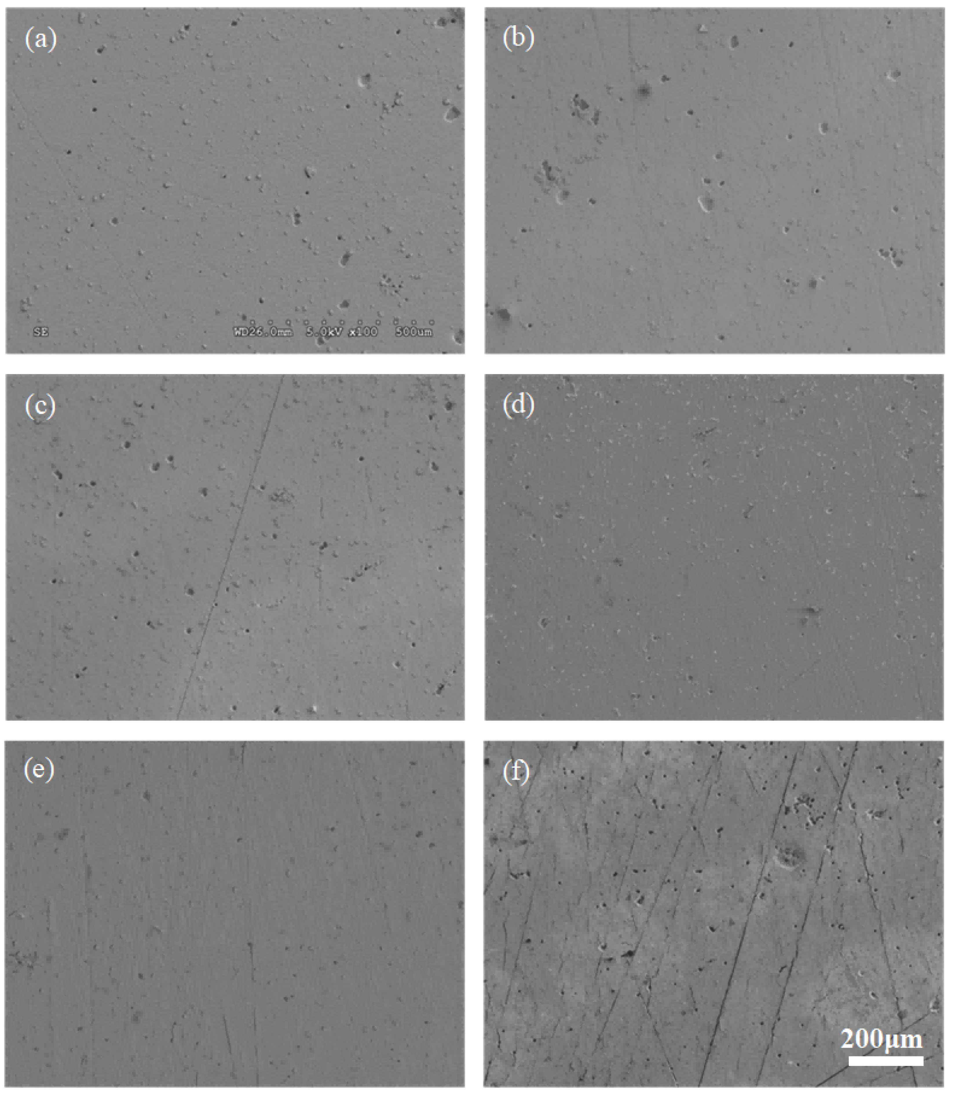
Figure 5 shows the surface morphology of the pure CeO2 coating after different numbers of thermal cycles between 1000 °C and room temperature. In the as-deposited state (Figure 5a), the surface exhibits cauliflower-like clusters formed by the shadowing effect during EB-PVD deposition, combined with limited adatom surface diffusion at 900 °C; these clusters are separated by inter-cluster boundaries containing micro-voids. During the initial thermal cycles, partial diffusion or detachment of these clusters produces numerous rounded protrusions and pores of various sizes. With increasing cycle number, atomic diffusion gradually reduces the protrusions and pores, making the surface smoother and denser. However, the pre-existing micro-voids at the original cluster boundaries cannot be completely eliminated, because the cluster size (2–5 μm) exceeds the effective atomic diffusion length at 1000 °C; these voids consequently evolve into the deep porosity seen in Figure 5d. After 480 cycles, additional cracks and pores appear, but no coating spallation occurs.
Figure 5.
Surface morphology of pure CeO2 coating after different thermal shock cycles. (a) 10 cycles; (b) 30 cycles; (c) 60 cycles; (d) 120 cycles; (e) 240 cycles; (f) 480 cycles.
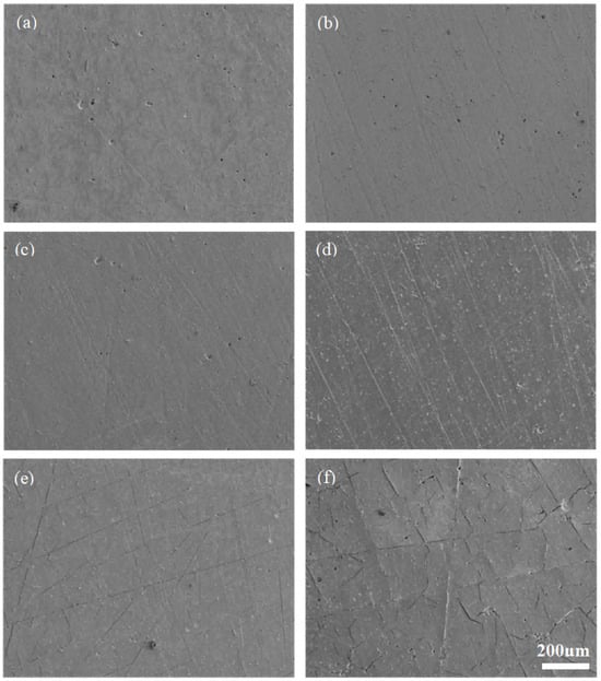
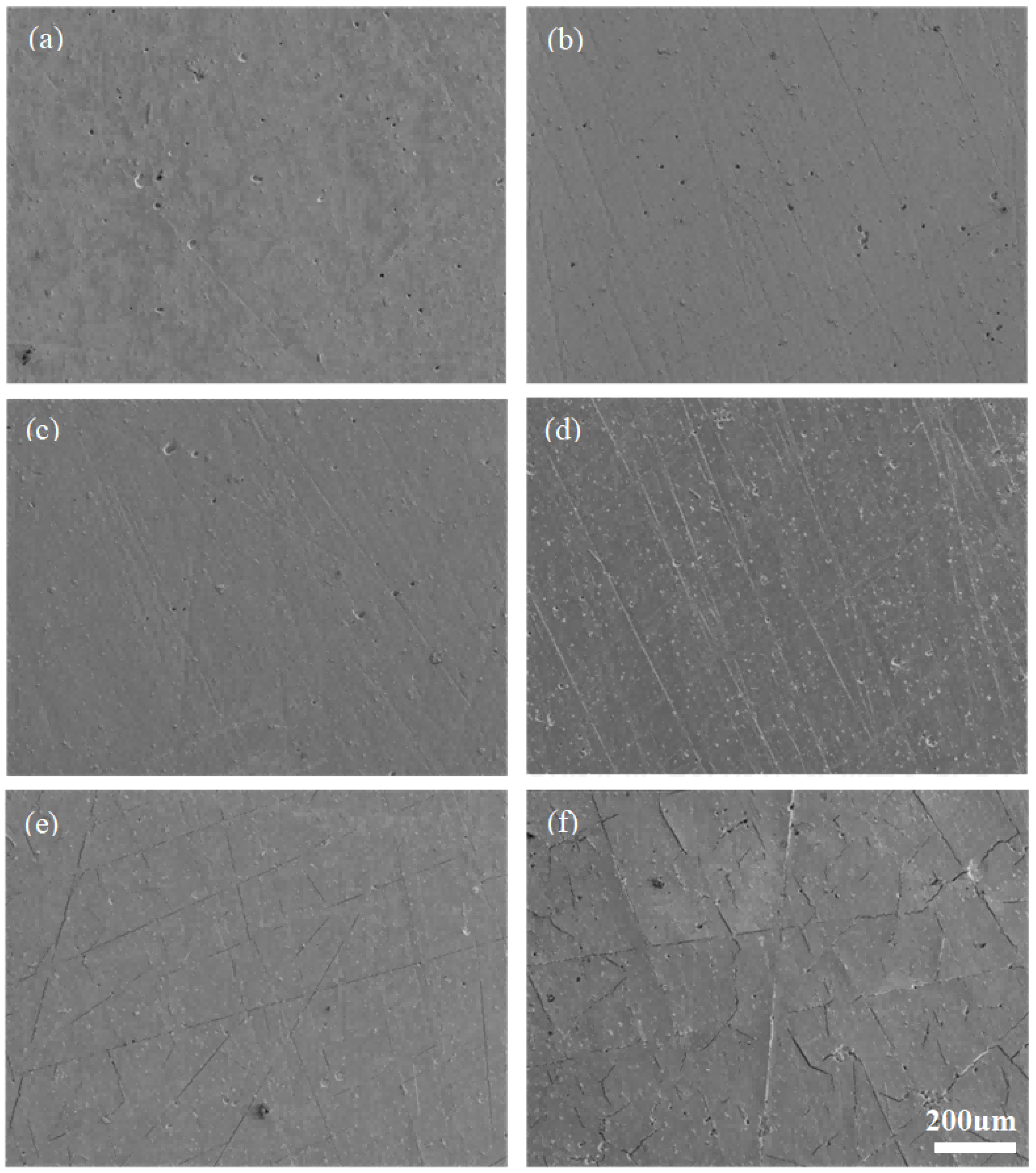
Figure 6 shows the surface morphology of the 20% LDC coating after different numbers of thermal cycles between 1000 °C and room temperature. As with pure CeO2, the initial cycles promote atomic diffusion and continuous densification, while atoms near internal pores diffuse and cause pore migration or coalescence at the surface; these voids gradually diminish in subsequent cycles. No microcracks are detected before 120 cycles. After 240 cycles, fine straight cracks begin to appear, and by 480 cycles the number of cracks—particularly irregular ones—increases to the point of being visible to the naked eye. Straight cracks mainly originate from linear defects introduced by substrate scratches during coating growth, whereas irregular cracks are primarily caused by internal thermal stress exceeding the grain boundary strength. No spallation occurs after 480 cycles, indicating that the interfacial bonding remained intact up to 480 cycles under the present conditions.
Figure 6.
Surface morphology of 20% LDC after different thermal shock cycles. (a) 10 cycles; (b) 30 cycles; (c) 60 cycles; (d) 120 cycles; (e)240 cycles; (f) 480 cycles.
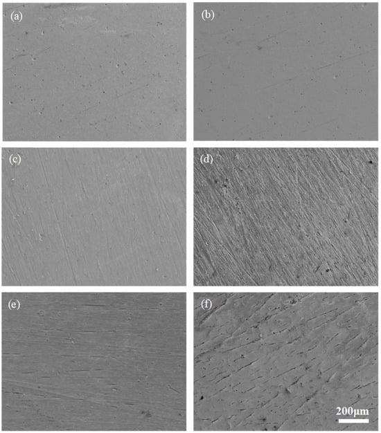
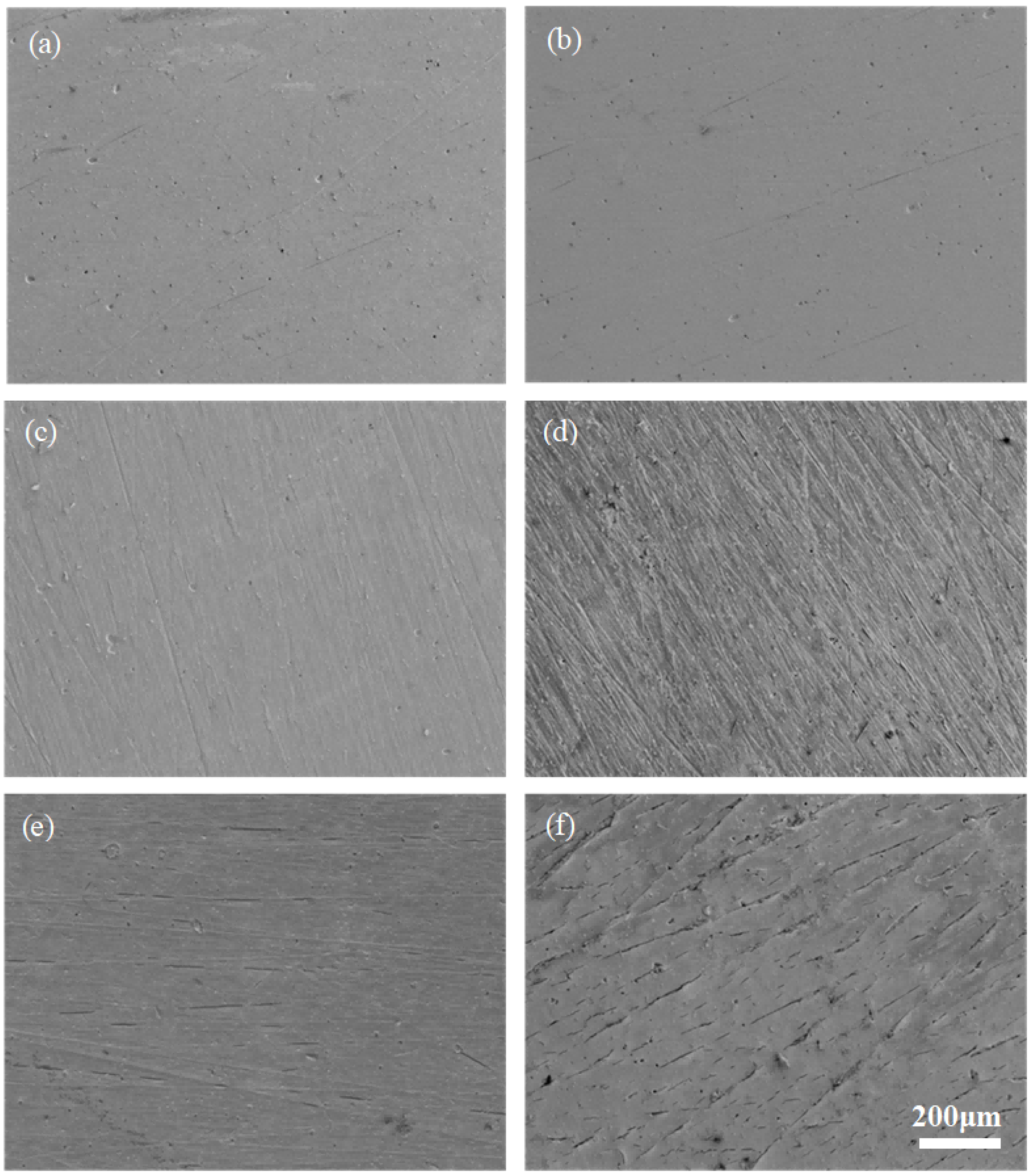
Figure 7 shows the surface morphology of the 40% LDC coating after different numbers of thermal cycles. The surface becomes smooth with only a few pores after 10 cycles, grows smoother with further pore reduction at 30 cycles, and shows a continued decrease in pore density but deteriorating surface finish at 60 cycles. By 120 cycles, the surface becomes notably rougher. A few short microcracks appear at 240 cycles, and their number increases further by 480 cycles; although they do not interconnect into long continuous cracks, they are arranged in straight lines, suggesting that they remain associated with inherent defects originating from substrate scratches.
Figure 7.
Surface morphology of 40% LDC after different thermal shock cycles. (a) 10 cycles; (b) 30 cycles; (c) 60 cycles; (d) 120 cycles; (e) 240 cycles; (f) 480 cycles.
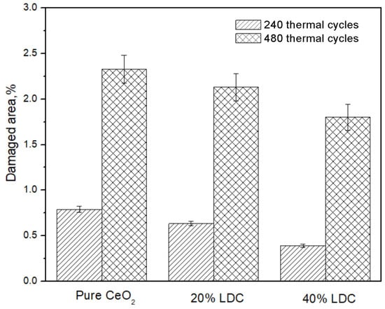
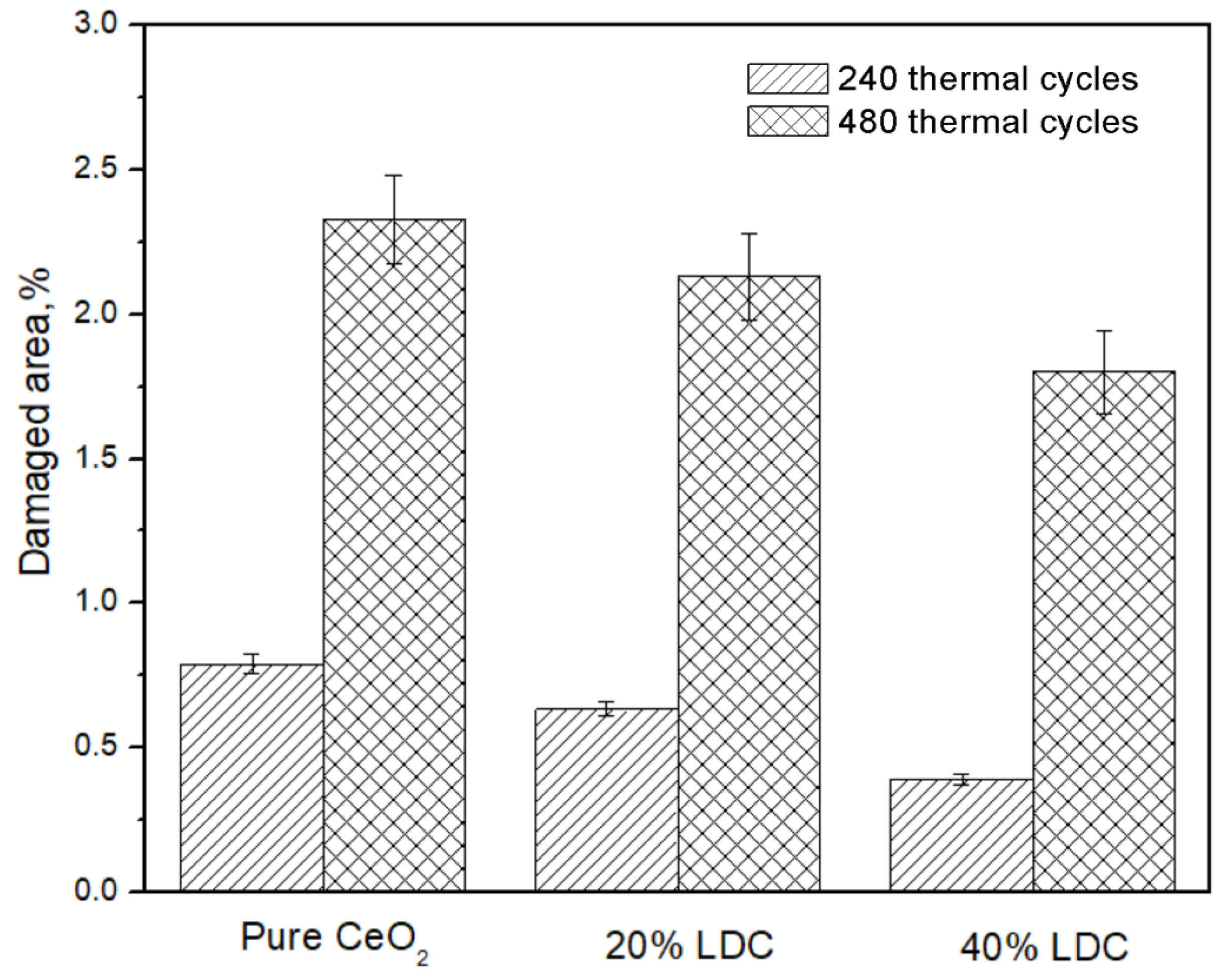
The percentage of damaged area on the surface of each LDC coating after 240 and 480 thermal cycles was statistically analyzed using Image-Pro Plus 6.0 software, and the results are presented in Figure 8. Among the LDC coatings, the pure CeO2 coating exhibits the most severe surface damage, followed by the 20% LDC coating, while the 40% LDC coating shows the least. A semi-quantitative assessment of densification based on the surface damage area fraction, microhardness, and elastic modulus is given at the end of Section 3.4.
Figure 8.
Percentage of damaged area on the surface of LDC coatings suffering 480 thermal cycles, data are presented as mean ± SD (n = 3).
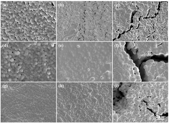
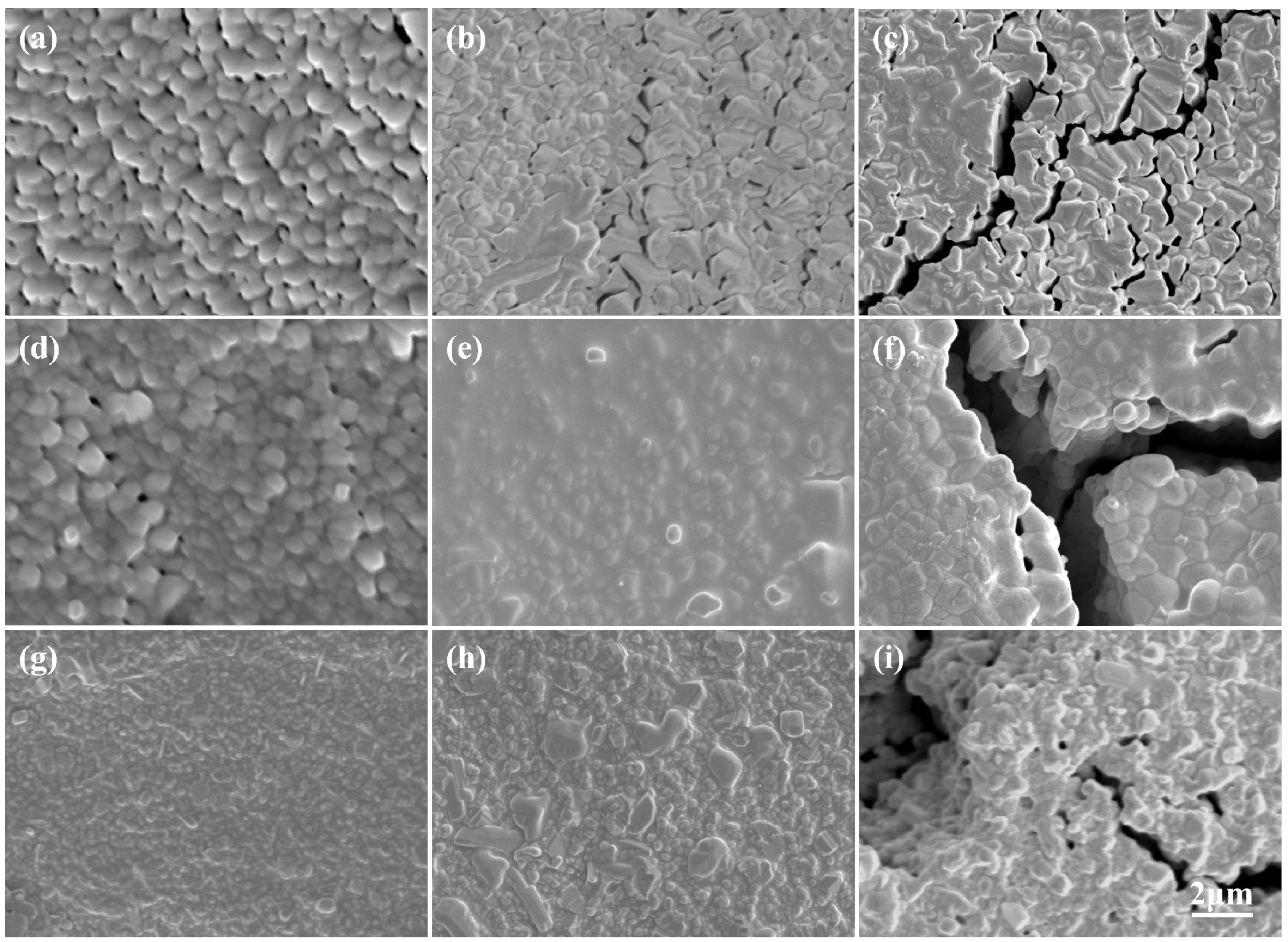
Figure 9 presents high-magnification comparative images at 120, 240, and 480 cycles that further elucidate the damage mechanism. Microcracks approximately 1 μm wide are observed after 240 cycles, and the crack width increases to about 3 μm after 480 cycles. The cracks exhibit a loose internal structure, with distinct step-like morphologies on both sides of the crack openings, suggesting that atoms from the crack edges have diffused into the crack interior. However, rapid crack propagation limits diffusion, so the cracks are not fully healed. Diffusion-driven crack healing in self-healing ceramics is effective only when the crack width falls below a critical threshold (typically < 1 μm) and under sufficient oxygen partial pressure [23], which is consistent with the partial healing observed here. The oxygen vacancies in La-doped ceria are known to enhance vacancy-mediated atomic diffusion, which may account for this healing tendency [24].
Figure 9.
High-magnification comparative images of the LDC coating after different numbers of thermal cycles. ((a–c) for pure coatings; (d–f) for 20% LDC; (g–i) for 40% LDC; (a,d,g) for 120 thermal cycles; (b,e,h) for 240 thermal cycles; (c,f,i) for 480 thermal cycles).
3.3. Cross-Sectional Morphology Evolution of La-CeO2 Coatings
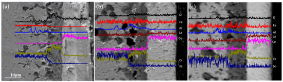
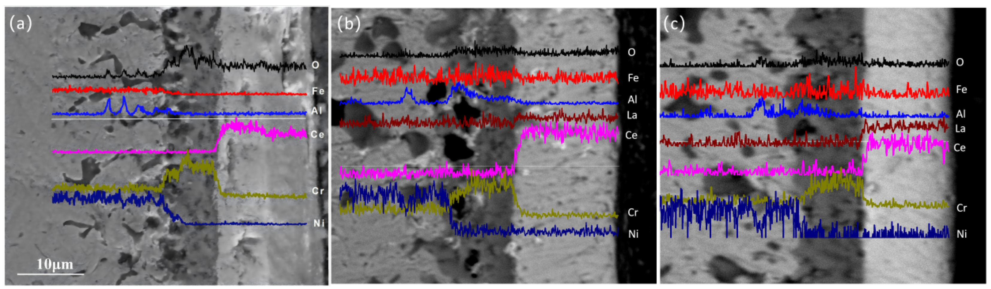
Figure 10 presents cross-sectional images of LDC coatings with varying La doping concentrations after 480 thermal cycles. The coatings remain firmly attached to the substrates, with no cracking observed at the coating–substrate interfaces, indicating good interfacial bonding under the present cycling conditions. A thick thermally grown oxide (TGO) layer has formed at the coating–substrate interface. In addition, a black phase is visible within the substrate beneath the TGO layer, consistent with the cross-sectional morphology observed for the pure CeO2 coating after 480 cycles.
Figure 10.
EDS line scanning profiles of the cross-section of LDC coating subjected to 480 thermal cycles, (a) Pure CeO2; (b) 20% LDC; (c) 40% LDC.
EDS line scan analysis was also performed on the 480 cycle specimen. The results reveal that the TGO layer is predominantly composed of Cr2O3, with alumina and titania as minor constituents. This composition differs from the α-Al2O3 TGO typical of conventional TBC systems, in which the bond coat serves as the aluminum reservoir. In the present work, the LDC coating was deposited directly onto the Haynes 214 substrate without a bond coat; Haynes 214 is a chromia-forming alloy, and the TGO composition therefore reflects the elements supplied by the substrate rather than by a bond coat. The presence of a Cr2O3-rich TGO is thus a likely consequence of the bond-coat-free architecture, rather than an anomaly. The black phase within the substrate is mainly Al2O3, along with a small amount of nickel oxide. No La2O3 or other La-containing compounds are detected in either the TGO layer or the internal oxidation zone of the substrate, indicating that La does not diffuse outward from the coating into the TGO or the substrate during thermal cycling. Nevertheless, the combined evidence from XRF analysis, hardness evolution, elastic modulus, and residual stress measurements consistently supports the conclusion that La remains in solid solution within the CeO2 lattice. Since the TGO layer (primarily Cr2O3) has a much lower thermal expansion coefficient than both the CeO2 coating and the substrate, its presence sandwiched between them readily promotes coating spallation. Therefore, the growth of the TGO layer should be suppressed.
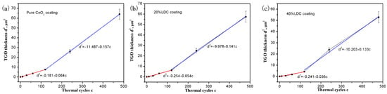
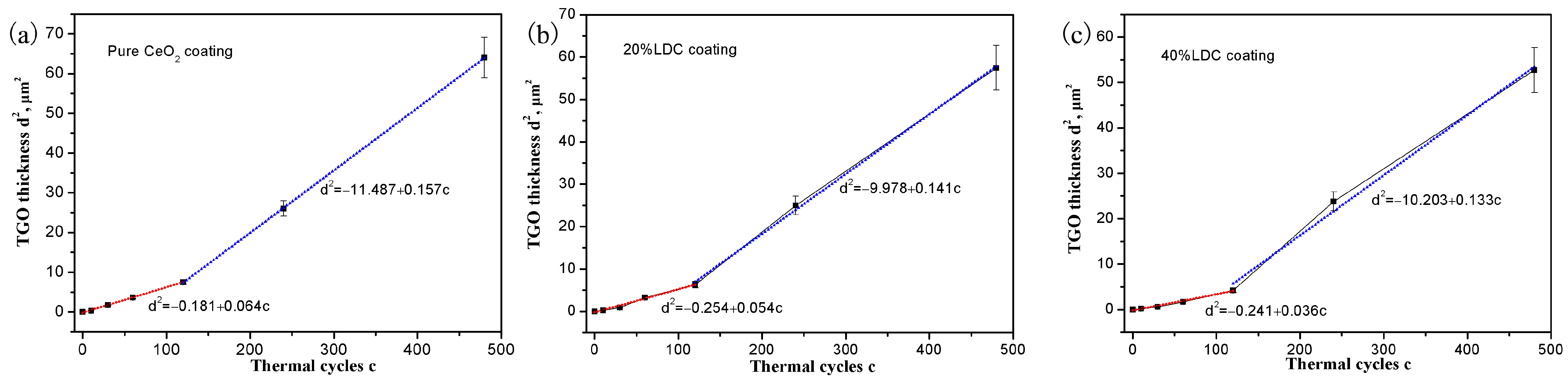
The thickness (d) of the TGO layer was measured as a function of thermal cycles (c), and the corresponding d2–c two-stage fitting curves are shown in Figure 11. With 120 thermal cycles as the dividing point, the growth of TGO layer at the coating/substrate interface exhibits two-stage parabolic kinetics before and after microcrack initiation. From the parabolic fitting of the initial crack-free stage (0–120 cycles), the parabolic rate constants Kp (μm2/cycle) were derived for each coating composition. The Kp values, which are proportional to the oxygen transport rate through the coating/TGO system, are as follows: 0.064 (pure CeO2), 0.054 (20% LDC) and 0.036 (40% LDC). Compared with pure CeO2, the 40% LDC coating reduces the oxygen transport rate by approximately 44% during the initial 120 cycles, suggesting that La doping may effectively suppresses TGO growth in the crack-free stage. After microcrack formation, the TGO growth rate increases significantly for all coatings, and the second-stage Kp value decreases only modestly from 0.157 (pure CeO2) to 0.133 (40% LDC). This reduced second-stage difference is attributed to the combined effects of La-induced grain refinement and an accelerated crack healing rate, and the doping benefit diminishes once short-circuit diffusion paths dominate.
Figure 11.
Two-stage fitting curves of TGO thickness (d2) versus thermal cycles (c) for LDC coating in thermal cycling, first stage fitting curves are in red lines, second stage fitting curves are in blue lines, (a) pure CeO2; (b) 20% LDC; (c) 40% LDC, data are presented as mean ± SD (n = 3).
3.4. Evolution of Surface Hardness During Thermal Cycling
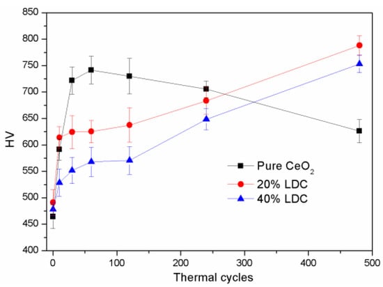
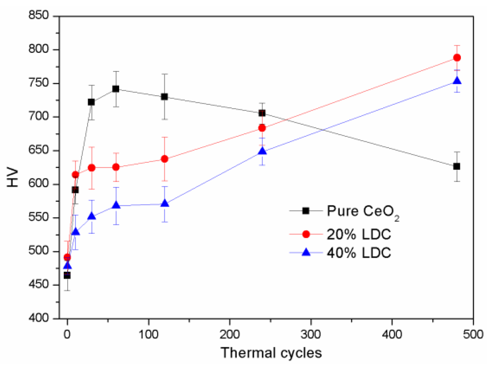
During thermal cycling, atomic diffusion continuously modifies the microstructure of the LDC coatings, leading to a rapid increase in density and, consequently, a marked change in surface microhardness. Figure 12 tracks the surface microhardness of the LDC coatings as a function of thermal cycles. During the first 10 cycles, both the LDC and pure CeO2 coatings exhibit a rapid increase in surface hardness. Between 10 and 120 cycles, the hardness of the LDC coatings remains essentially stable or increases only slightly. After 120 cycles, the hardness resumes a more rapid increase. This trend contrasts with that observed for the pure CeO2 coatings, whose hardness first increases and then decreases (starting to decline after 60 cycles). After 480 cycles, the hardness of the doped CeO2 coatings reaches approximately 750–780 HV, significantly higher than that of the pure CeO2 coating.
Figure 12.
Hardness of LDC coatings during thermal shock cycles, data are presented as mean ± SD (n = 3).
The three-stage hardness evolution of the La-doped coatings is not merely a property difference from pure CeO2; it is a mechanistic indicator of the coupling among densification, TGO thickening, and La-induced lattice distortion. The initial rapid increase reflects pore closure and densification; the plateau arises from the competition between densification-induced hardening and the progressively increasing tensile stress associated with TGO growth during cooling; and the secondary increase occurs once porosity is largely eliminated and the La-induced compressive elastic strain field becomes dominant. In contrast, pure CeO2 lacks this doping-induced strain field and therefore exhibits an increase-then-decline trend.
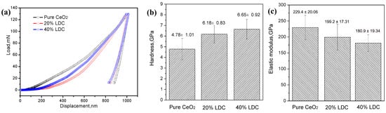
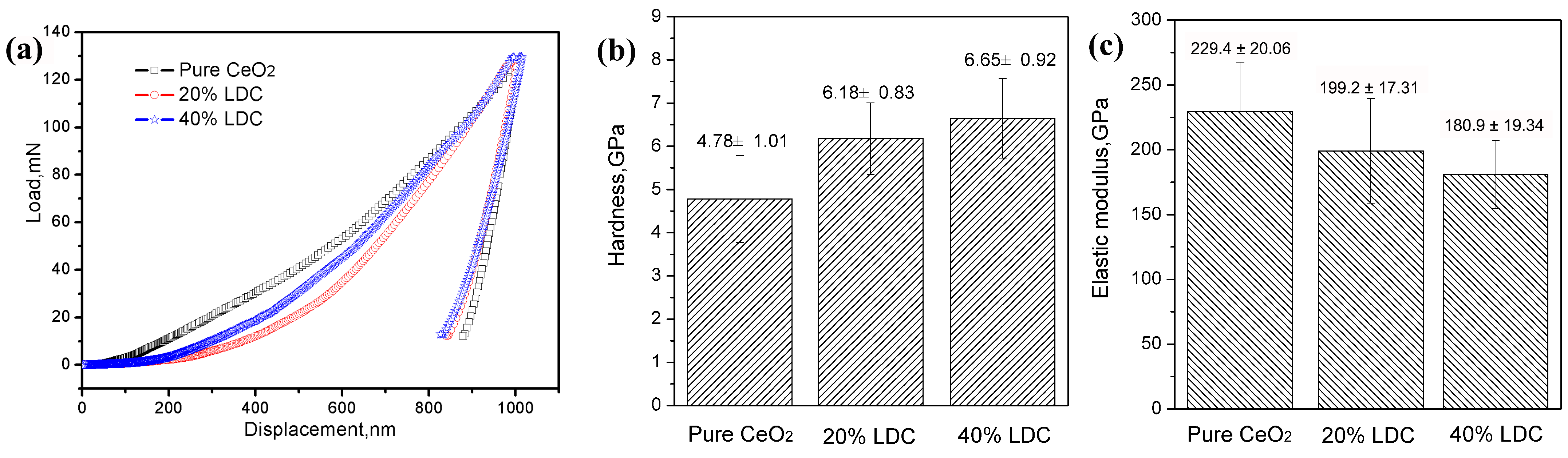
Nanoindentation tests were employed to evaluate the microhardness and elastic modulus of the samples, as presented in Figure 13. The elastic moduli are 229.4 ± 20.06 GPa for pure CeO2, 199.2 ± 17.31 GPa for 20% LDC, and 180.9 ± 19.34 GPa for 40% LDC. The results indicate that the microhardness increases, whereas the elastic modulus decreases with increasing La concentration. The decrease in elastic modulus with increasing La content (229.4 → 199.2 → 180.9 GPa) cannot be attributed to composition alone. Three contributions are expected to coexist: intrinsic lattice softening due to La–O bonding and lattice expansion, a higher retained porosity/lower degree of sintering in the La-doped coatings, and the compressive residual stress state. The present dataset does not allow these contributions to be separated quantitatively; the modulus values should therefore be interpreted as effective coating moduli rather than as intrinsic materials properties. The measured values reflect the combined effects of intrinsic lattice stiffness, coating density, residual stress, and microstructural features such as grain size and grain boundary density.
Figure 13.
Nanoindentation results of LDC coatings with different La concentrations: (a) load–displacement curves; (b) hardness; (c) elastic modulus of LDC coatings with different La concentrations.
Because the absolute density of the thin columnar coatings could not be measured directly, densification was assessed semi-quantitatively using three independent indicators: the surface damage area fraction (Figure 8), the surface microhardness (Figure 12), and the elastic modulus (Figure 13). All three indicators show that rapid densification occurs during the first ~120 cycles for all compositions, whereas the La-doped coatings retain a more compliant structure and a lower damage area fraction after 480 cycles. These indicators are used as relative measures of densification rather than as absolute density values.
3.5. Evaluation of Residual Stress in As-Deposited Coatings
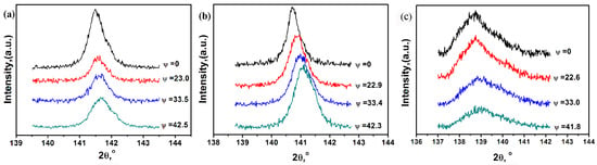
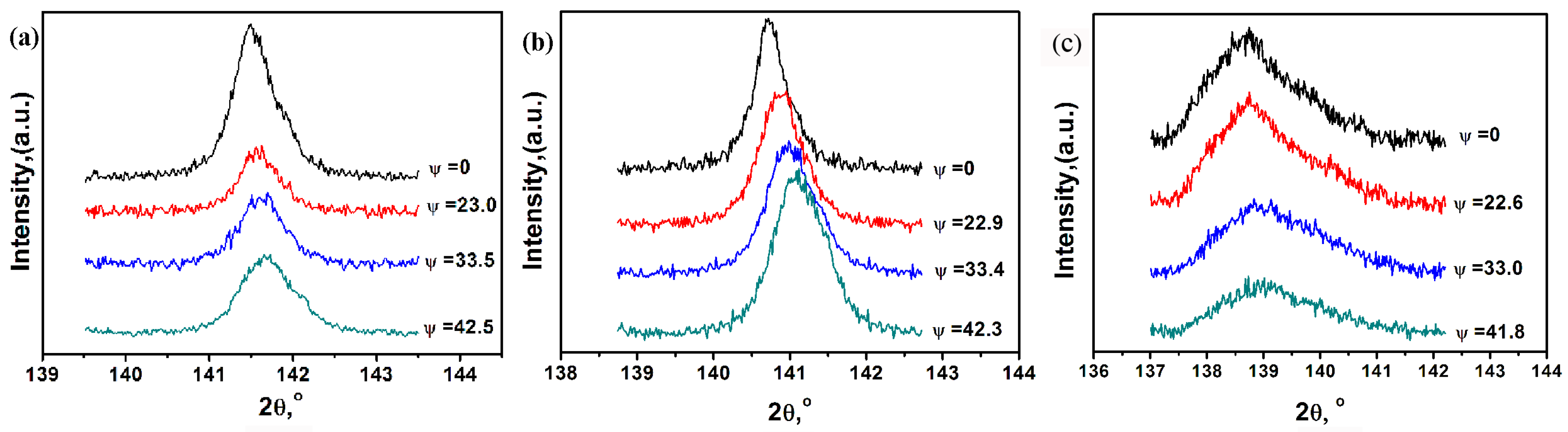
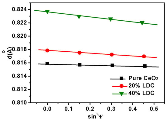
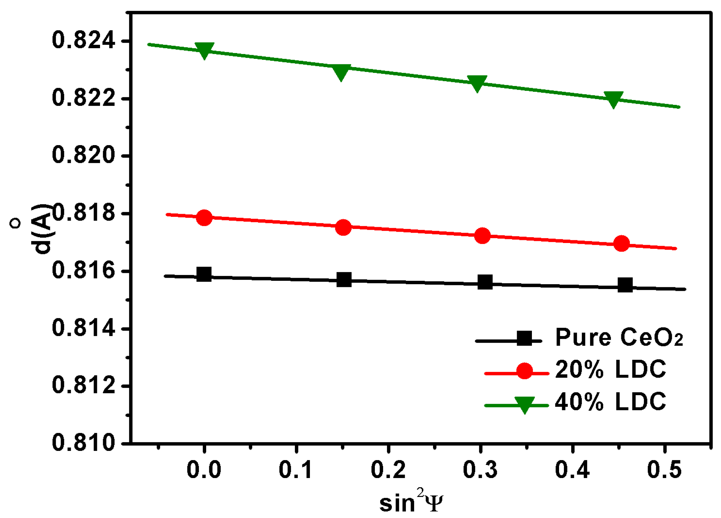
To gain deeper insight into the origins of coating cracking, the residual stress of the as-deposited coatings was analyzed using grazing-incidence X-ray diffraction (XRD). Diffraction spectra of the (622) crystal plane were collected at various ψ angles (Figure 14). As ψ increases, the diffraction peaks shift toward higher angles, indicating that the residual stress in the coatings is compressive in nature. Similar residual stress states have been reported for strongly textured PVD coatings using the XRD sin2ψ method [25,26]. This compressive residual stress is beneficial for relieving the tensile stress generated during thermal cycling, thereby enhancing the crack resistance of the coatings. At a fixed ψ angle, increasing the La doping concentration shifts the diffraction peak to lower angles, reflecting an increase in lattice constant—i.e., lattice expansion—which is consistent with the XRD results obtained in the 20–90° range. The (622) interplanar spacing at different ψ angles is calculated from the peak positions, and the d–sin2ψ relationship curves are plotted in Figure 15. These curves can be approximately fitted by straight lines, and the corresponding slopes M are listed in Table 3. A Poisson’s ratio of 0.25 was adopted for all coatings. Using these parameters in conjunction with Equation (2), the residual stress of each as-deposited coating was calculated, and the results are summarized in Table 3. For the pure CeO2 coating, the residual compressive stress measured by the sin2ψ method was −98 MPa, significantly lower than those of 20% LDC (−318.3 MPa) and 40% LDC (−475.8 MPa). This reflects that the lattice distortion induced by La doping generates substantial residual compressive stress. Since La3+ (approximately 1.16 Å) is larger than Ce4+ (approximately 0.97 Å), its incorporation produces an anisotropic strain field that varies with crystallographic orientation, causing the interplanar spacings of different compositions to deviate from the ideal d–sin2ψ linear relationship to varying degrees.
Figure 14.
XRD patterns of (622) plane of LDC coatings with different La concentration (a) pure CeO2; (b) 20% LDC; (c) 40% LDC.
Figure 15.
Interplanar distance d versus sin2ψ for LDC coatings with different La concentration.
Table 3.
Residual stress in LDC coatings.
The sin2ψ residual stress analysis on the (622) plane provides a direct measure of the as-deposited mechanical state of EB-PVD columnar LDC coatings, which has not been reported for this architecture. The large standard deviations in Table 3 reflect orientation-dependent lattice distortion induced by La3+ incorporation—i.e., La doping does not expand the CeO2 lattice uniformly in all crystallographic directions—rather than simple measurement scatter. This anisotropic compressive stress state is beneficial for accommodating the thermal mismatch strain during cycling.
4. Discussion
The LDC coating underwent 480 thermal cycles between 1000 °C and room temperature without spallation. In the following section, the evolution of internal stresses during thermal cycling is examined as a possible explanation for the observed cycling behaviour.
First, the initial residual stress within the as-deposited LDC coating should be considered.
In doped LDC coatings, at least two types of internal stress are present: compressive stress induced by temperature changes, and compressive stress arising from doping-related lattice expansion, in addition to stress originating from lattice defects. The total residual stress is a superposition of these contributions. Its magnitude and distribution depend critically on the deposition temperature, the coating microstructure, and the dopant-induced lattice distortion [27,28].
Second, the thermal mismatch stress during thermal shock cycling should be discussed. Thermal mismatch stress primarily arises from differences in the coefficients of thermal expansion (CTEs) among the constituent layers [29,30]. During the initial stage of thermal cycling within 120 cycles, which corresponds to a densification stage, the TGO layer remains very thin, and the interfacial thermal mismatch stress is dominated by the CTE mismatch between the LDC coating and the Ni-based alloy. According to the literature, the CTE of LDC coatings over the range of 300–1200 °C is 11.8–12.9 × 10⁻⁶/K, which matches that of Ni-based alloys closely, resulting in relatively small initial interfacial thermal stresses.
As thermal cycling proceeds, atomic diffusion at the interface accelerates and the intragranular defect density decreases, leading to increased coating densification, higher hardness, and reduced internal residual stress, which in turn reduces the strain tolerance of the columnar structure [31].
At this stage, the TGO layer continues to thicken with increasing thermal cycles. Since the CTE of the TGO is lower than that of the LDC coating, the thermal expansion mismatch generates compressive stress in the coating during heating and transforms into tensile stress during cooling. Compressive stress tends to increase hardness, whereas tensile stress tends to decrease it. Densification promotes an increase in hardness, while the progressively increasing tensile stress counteracts this effect, resulting in a relatively stable plateau in hardness. La doping significantly reduces the initial crystallite size (from 75 nm for pure CeO2 to 49 nm for 40% LDC), which increases the grain boundary density and thereby helps to dissipate the internal stress caused jointly by doping and densification. However, high-magnification SEM observations (Figure 9) indicate that rapid grain growth occurs during the initial thermal cycles, which diminishes the initial crystallite size differences among the three compositions. Therefore, quantitatively separating the independent contribution of crystallite size from the present dataset remains challenging.
With increasing thermal cycles, the TGO layer thickens continuously, and the interfacial thermal stress gradually becomes distributed across two interfaces: LDC/TGO and TGO/Ni-based alloy. Finite element simulations indicate that the stress magnitude increases significantly with TGO thickness, especially in regions of high interfacial curvature [27,32]. Since the CTE of the TGO layer is significantly lower than those of the LDC coating and the Ni-based alloy, the Ni-based alloy and LDC coating expand more than the TGO layer during heating, thereby inducing compressive stress in the LDC coating and tensile stress in the TGO layer; upon cooling, the internal stresses reverse, with tensile stress in the LDC coating and compressive stress in the TGO layer. This cyclic tension–compression transition has been well documented in EB-PVD TBC failure models [28]. Given that the bonding strength of columnar grain boundaries in ceramic materials is relatively weak, microcracks tend to initiate when the local tensile stress in the LDC coating exceeds a critical threshold. The LDC coating then enters the microcrack formation stage. At this stage, densification advances further, and the doping effect of La becomes more pronounced: La3+ has a larger ionic radius than Ce4+, which compresses the surrounding atoms and creates an elastic strain field. When the coating density is low, this elastic distortion is accommodated by internal defects; however, as these defects are eliminated and the density increases, the doping-induced elastic distortion contributes internal compressive stress, thereby again increasing the hardness of the LDC coating. In contrast, the pure CeO2 coating lacks this elastic deformation caused by lattice distortion, and its hardness continues to decrease.
The densification inferred from the hardness and modulus evolution (Section 3.2) is consistent with the two-stage TGO kinetics: the initial stage (0–120 cycles) corresponds to pore closure and coating densification, during which the oxygen transport path is gradually reduced, whereas the second stage begins once microcracks provide short-circuit diffusion paths.
The choice of La3+ rather than a smaller trivalent dopant is consistent with the observed TGO growth kinetics. The initial-stage Kp decreases from 0.064 μm2/cycle for pure CeO2 to 0.036 μm2/cycle for 40% LDC (Figure 11), consistent with La incorporation reducing the oxygen transport rate through the coating by approximately 44% in the crack-free stage. This suppression is not simply a consequence of lattice expansion. It may reflect the defect-chemical role of the large La3+ ion in modulating oxygen vacancy concentration and mobility. Smaller trivalent dopants, which bind oxygen vacancies more strongly at first-neighbour sites, would be expected to exhibit a different balance between vacancy generation and vacancy trapping, and hence a different TGO growth response.
To delay the transition of the protective performance of LDC coatings from the first densification stage to the second microcrack-generation stage—and thereby extend the thermal cycling lifetime of the LDC coating—several strategies can be considered based on the present findings. First, optimizing the La doping concentration is the most direct approach. The La content needs to be precisely controlled to avoid excessive enrichment of doped La along specific crystallographic orientations, which would cause stress concentration. Second, increasing the substrate temperature during EB-PVD deposition enhances adatom mobility and the interfacial bonding strength between the coating and the substrate, while also promoting coating densification. A dense microstructure with fewer micropores reduces the number of potential crack initiation sites and improves the overall structural integrity of the coating. Third, optimizing the deposition rate provides a feasible microstructural engineering pathway. By optimizing the deposition rate, a fine and dense columnar grain structure with high interfacial bonding strength can be obtained, which would simultaneously improve strain tolerance and mechanical robustness. These strategies, whether used individually or in combination, provide practical guidance for the future development of LDC-based thermal barrier coatings with longer service lifetimes.
The mechanical-property evolution is consistent with the thermal shock outcome. The La-doped coatings exhibit a lower elastic modulus and a higher as-deposited compressive residual stress than pure CeO2, both of which favor the accommodation of thermal mismatch strain during cycling. This is reflected in the lower surface damage area fraction (Figure 8) and in the absence of spallation after 480 cycles. It should be emphasized, however, that the present experiments do not isolate the mechanical contribution from the TGO-growth contribution; the correlation reported here is therefore consistent with, but does not by itself prove, a causal role of the mechanical state in extending thermal shock life.
Finally, the thermal diffusion behavior of atoms also plays an important role in crack development within the coating. During thermal cycling, the characteristic diffusion distance of atoms can be estimated as , where D is the diffusion coefficient and t is the holding time per cycle (600 s at 1000 °C). Even with enhanced diffusion coefficients in nanocrystalline ceria, the diffusion length per cycle is typically only on the order of tens to hundreds of nanometers. The original cauliflower-like clusters are micron-sized (2–5 μm), so complete pore closure through atomic diffusion is kinetically inhibited. Therefore, although the surface becomes smoother, the inter-cluster voids remain as deep pores.
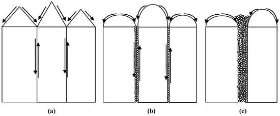
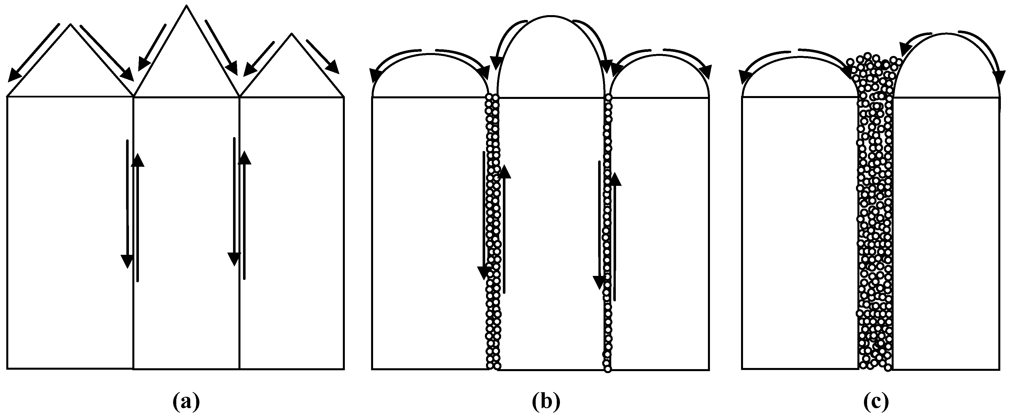
Comprehensive analysis suggests that crack initiation and propagation in the LDC coating may be mainly controlled by internal stress and grain boundary bonding strength [33,34]. The evolution of internal stress is primarily governed by densification and TGO growth, while grain boundary bonding strength is affected by densification and atomic thermal diffusion. When microcracks propagate slowly, atomic diffusion near the crack faces may cause local mass transport, which can reduce or even heal narrow cracks. As internal stress continues to increase, crack propagation accelerates and crack width increases. When the crack exceeds a critical threshold width, the diffusion distance becomes too large, and only slight morphological changes occur at the crack edges rather than complete closure. Based on SEM morphological statistics, the crack width associated with partial healing is in the range of 1–3 μm, while the critical threshold for complete healing may be even lower (<1 μm). On the basis of these findings and general diffusion principles, we propose a schematic diagram (Figure 16) to illustrate the atomic diffusion behavior that may occur on the surface and along grain boundaries. This schematic is consistent with diffusion-driven crack healing models reported in the literature for ceramic systems [23,31].
Figure 16.
Schematic illustration of atomic diffusion on the surface and along grain boundaries: (a) initial state + surface diffusion; (b) microcrack formation + grain boundary diffusion; (c) crack healing.
Several limitations of the present study should be acknowledged. First, the thermal cycling test was terminated at 480 cycles because of substrate oxidation and bending, so the reported durability is a lower bound rather than a measured life limit. Second, the present experiments do not isolate the mechanical contribution from the TGO-growth contribution; the correlation between the mechanical state and thermal shock outcome is therefore consistent with, but does not by itself prove, a causal role. Third, the absolute density of the thin columnar coatings could not be measured directly, so densification was assessed semi-quantitatively through surface damage area fraction, microhardness, and elastic modulus. These limitations define the scope of the present mechanistic conclusions and point to future work on free-standing coatings and longer-duration cycling.
5. Conclusions
This study systematically evaluated the high-cycle thermal shock resistance of LDC coatings fabricated by EB-PVD on nickel-based superalloys. The main findings are as follows:
- (1)
- All LDC coatings survived 480 thermal cycles between room temperature and 1000 °C without spallation. This 480-cycle result represents a lower bound on coating durability, because the test was terminated owing to severe oxidation and warping of the uncoated substrate rather than premature failure of the ceramic coating.
- (2)
- Within this lower-bound framework, the extent of surface damage decreases monotonically with increasing La content: the 40% LDC coating shows the least surface damage and the slowest initial-stage TGO growth, while pure CeO2 shows the most severe damage. This monotonic trend in damage area, together with the La-dependent TGO kinetics, constitutes the main outcome of this work, rather than an absolute lifetime record.
- (3)
- The growth of TGO layer at the coating/substrate interface displays two-stage parabolic kinetics during thermal cycling, with a slower rate in the initial crack-free stage (0–120 cycles) and a faster rate after microcrack formation. The TGO is predominantly Cr2O3 because the coating was deposited directly onto the chromia-forming Haynes 214 substrate without a bond coat. The two-stage kinetics therefore pertain to this bond-coat-free architecture.
- (4)
- The La-doped coatings exhibit a three-stage hardness evolution during thermal cycling (rapid initial increase, stable plateau, and secondary increase), which differs fundamentally from that of pure CeO2. This behavior is attributed to the combined effects of densification and La-induced lattice distortion.
- (5)
- Crack initiation and propagation are governed by residual stress, coating densification, and TGO growth. Localized mass transport via atomic diffusion near crack surfaces is possible but limited by crack width; for wide cracks, only marginal morphological changes occur at the crack edges rather than complete closure.
Taken together, these findings provide mechanistic understanding and design guidance for extending the first densification stage and delaying the microcrack-dominated second stage in bond-coat-free LDC coatings, rather than a claim of universal superiority over established ceramic systems.
Author Contributions
Conceptualization, J.H. and M.Z.; methodology, X.X. and G.S.; validation, J.S., Y.L. and Z.B.; formal analysis, J.H., D.M. and M.Z.; investigation, Z.B., X.X., Y.L. and D.M.; resources, G.S. and M.Z.; data curation, J.H., D.M. and J.S.; writing—original draft preparation, J.H.; writing—review and editing, J.H. and M.Z.; visualization, J.H.; supervision, J.H. and M.Z.; project administration J.H.; funding acquisition J.H., J.S., D.M. and M.Z. All authors have read and agreed to the published version of the manuscript.
Funding
This research was funded by the National Natural Science Foundation of China (52501207), the Natural Science Foundation of Hunan Province (2025JJ70134, 2024JJ7118), and the Hengyang City Science and Technology Plan Project (511209723015).
Data Availability Statement
The raw data supporting the conclusions of this article will be made available by the authors upon request.
Acknowledgments
The authors wish to acknowledge the Centre for Materials Analysis and Testing at Harbin Institute of Technology.
Conflicts of Interest
The authors declare no conflicts of interest.
Abbreviations
The following abbreviations are used in this manuscript:
| EB-PVD | electron beam physical vapor deposition |
| LDC | La-doped CeO2 |
| TGO | thermally grown oxide |
| TBC | thermal barrier coating |
| TEC | thermal expansion coefficient |
| SEM | scanning electron microscope |
| EDS | Energy-dispersive X-ray spectroscopy |
| XRD | X-ray diffractometer |
| XRF | X-ray Fluorescence |
| rpm | revolutions per minute |
References
- Gudivada, G.; Pandey, A.K. Recent developments in nickel-based superalloys for gas turbine applications: Review. J. Alloys Compd. 2023, 963, 171128. [Google Scholar] [CrossRef] [Scilit]
- Pollock, T.M.; Tin, S. Nickel-based superalloys for advanced turbine engines: Chemistry, microstructure and properties. J. Propuls. Power 2006, 22, 361–374. [Google Scholar] [CrossRef] [Scilit]
- Perepezko, J.H. The hotter the engine, the better. Science 2009, 326, 1068–1069. [Google Scholar] [CrossRef] [Scilit] [PubMed]
- Padture, N.P. Advanced structural ceramics in aerospace propulsion. Nat. Mater. 2016, 15, 804–809. [Google Scholar] [CrossRef] [Scilit] [PubMed]
- Clarke, D.R.; Oechsner, M.; Padture, N.P. Thermal-barrier coatings for more efficient gas-turbine engines. MRS Bull. 2012, 37, 891–902. [Google Scholar] [CrossRef] [Scilit]
- Diwahar, D.; Manivachakan, V.; Syed, R.B. An overview of rare-earth doped ceramic thermal barrier coatings for high-temperature performance of nickel-based superalloys. High Temp. Corros. Mater. 2025, 102, 17. [Google Scholar] [CrossRef] [Scilit]
- Schulz, U.; Leyens, C.; Fritscher, K.; Peters, M.; Saruhan-Brings, B.; Lavigne, O.; Dorvaux, J.M.; Poulain, M.; Mévrel, R.; Caliez, M. Some recent trends in research and technology of advanced thermal barrier coatings. Aerosp. Sci. Technol. 2003, 7, 73–80. [Google Scholar] [CrossRef] [Scilit]
- Yuan, B.; Harvey, C.M.; Thomson, R.C.; Critchlow, G.W.; Rickerby, D.; Wang, S. A new spallation mechanism of thermal barrier coatings and a generalized mechanical model. Compos. Struct. 2019, 227, 111314. [Google Scholar] [CrossRef] [Scilit]
- Rabiei, A.; Evans, A.G. Failure mechanisms associated with the thermally grown oxide in plasma-sprayed thermal barrier coatings. Acta Mater. 2000, 48, 3963–3976. [Google Scholar] [CrossRef] [Scilit]
- Che, J.W.; Ren, G.L.; Wang, X.Z. Synergistically enhanced thermophysical and mechanical properties of La2(Hf1−xCex)2O7 for thermal barrier coatings. Ceram. Int. 2025, 51, 56123–56132. [Google Scholar] [CrossRef] [Scilit]
- Chen, X.G.; Zhang, H.M.; Zhang, H.S.; Zhao, Y.D.; Li, G. Ce1−xSmxO2−x/2—A novel type of ceramic material for thermal barrier coatings. J. Adv. Ceram. 2016, 5, 244–252. [Google Scholar] [CrossRef] [Scilit]
- Morrison, T.D.; Wood, E.S.; Weck, P.F.; Kim, E.; Woo, S.O.; Nelson, A.T.; Naugle, D.G. A comprehensive assessment of the low-temperature thermal properties and thermodynamic functions of CeO2. J. Chem. Phys. 2019, 151, 044202. [Google Scholar] [CrossRef] [Scilit] [PubMed]
- Praveen, K.; Kim, H.; Govindarajan, S.; Lee, M.W. Cubic fluorite-based lanthanum cerium oxide thermal barrier top-coat fabrication, properties, and performance: Present status and prospects. J. Eur. Ceram. Soc. 2024, 44, 116804. [Google Scholar] [CrossRef] [Scilit]
- Watanabe, M.; Nakamura, H.; Suzuki, K.; Machida, M.; Kato, M. Defect equilibria and thermophysical properties of CeO2−x based on experimental data and density functional theory calculation result. J. Am. Ceram. Soc. 2022, 105, 2248–2257. [Google Scholar] [CrossRef] [Scilit]
- Kohlmann, D.; Wulfmeier, H.; Schewe, M.; Kogut, I.; Steiner, C.; Moos, R.; Rembe, C.; Fritze, H. Chemical expansion of CeO2−δ and Ce0.8Zr0.2O2−δ thin films determined by laser Doppler vibrometry at high temperatures and different oxygen partial pressures. J. Mater. Sci. 2023, 58, 1481–1504. [Google Scholar] [CrossRef] [Scilit]
- Lei, P.H.; Ji, X.Y.; Qiu, J.; Si, J.X.; Peng, T.; Teng, C.Q.; Wu, L. The influence of grain size on microstructure evolution in CeO2 under xenon ion irradiation. Nanomaterials 2024, 14, 1498. [Google Scholar] [CrossRef] [Scilit] [PubMed]
- Zamudio-García, J.; Porras-Vázquez, J.M.; Cabeza, A.; Canales-Vázquez, J.; Losilla, E.R.; Marrero-López, D. Influence of rare-earth doping content and type on phase transformation and transport properties in highly doped CeO2. ACS Appl. Mater. Interfaces 2024, 16, 42198–42209. [Google Scholar] [CrossRef] [Scilit] [PubMed]
- Loche, D.; Morgan, L.M.; Casu, A.; Mountjoy, G.; O’Regan, C.; Corrias, A.; Falqui, A. Determining the maximum lanthanum incorporation in the fluorite structure of La-doped ceria nanocubes for enhanced redox ability. RSC Adv. 2019, 9, 6745–6751. [Google Scholar] [CrossRef] [Scilit] [PubMed]
- Gupta, M.; Shirbhate, S.C.; Rambadey, O.V.; Acharya, S.A.; Sagdeo, P.R. Temperature-dependent delocalization of oxygen vacancies in La-substituted CeO2. ACS Appl. Energy Mater. 2022, 5, 9759–9769. [Google Scholar] [CrossRef] [Scilit]
- Gong, W.; Zhang, R.; Chen, Z. Thermodynamic modelling and applications of Ce−La−O phase diagram. Trans. Nonferrous Met. Soc. China 2011, 21, 2671–2676. [Google Scholar] [CrossRef] [Scilit]
- Michalska, M.; Lemanski, K.; Sikora, A. Spectroscopic and structural properties of CeO2 nanocrystals doped with La3+, Nd3+ and modified on their surface with Ag nanoparticles. Heliyon 2021, 7, e07195. [Google Scholar] [CrossRef] [Scilit] [PubMed]
- Yi, H.; Che, J.W.; Xu, Z.H.; Liang, G.Y.; Liu, X.Y. Sintering resistance of La2Ce2O7, La2Zr2O7, and yttria stabilized zirconia ceramics. Ceram. Int. 2021, 47, 4197–4205. [Google Scholar] [CrossRef] [Scilit]
- Hutchinson, R.G.; Fleck, N.A.; Cocks, A.C.F. A sintering model for thermal barrier coatings. Acta Mater. 2006, 54, 1297–1306. [Google Scholar] [CrossRef] [Scilit]
- Aadhavan, R.; Babu, K.S. Role of oxygen vacancy tuning in EBPVD deposited LaxCe1−xO2−δ films in high temperature oxidation protection. RSC Adv. 2015, 5, 83538–83545. [Google Scholar] [CrossRef] [Scilit]
- Luo, Q.S.; Yang, S.C. Uncertainty of the X-ray diffraction (XRD) sin2ψ technique in measuring residual stresses of physical vapor deposition (PVD) hard coatings. Coatings 2017, 7, 128. [Google Scholar] [CrossRef] [Scilit]
- Liu, W.; Liu, H.Q.; Ou, G.; Pan, W. Residual stress-dependent electric conductivity of sputtered co-doped CeO2 thin-film electrolyte. J. Appl. Phys. 2011, 109, 084321. [Google Scholar] [CrossRef] [Scilit]
- Xiao, Y.Q.; Liu, Z.Y.; Peng, X.M.; Zhu, W.; Zhou, Y.C.; Yang, L. Spallation mechanism of TBCs with real interface morphology considering growth and thermal stresses based on fracture phase field. Surf. Coat. Technol. 2023, 458, 129356. [Google Scholar] [CrossRef] [Scilit]
- Jing, F.L.; Yang, J.J.; Yang, Z.M.; Zeng, W. Critical compressive strain and interfacial damage evolution of EB-PVD thermal barrier coating. Mater. Sci. Eng. A 2020, 776, 139038. [Google Scholar] [CrossRef] [Scilit]
- Yan, J.R.; Chen, K.Y.; Wang, X. Failure and damage evaluation of thermal barrier coatings under thermal cyclic environments: Multi-physics modeling. Int. J. Fract. 2025, 249, 64. [Google Scholar] [CrossRef] [Scilit]
- Padture, N.P.; Gell, M.; Jordan, E.H. Thermal barrier coatings for gas-turbine engine applications. Science 2002, 296, 280–284. [Google Scholar] [CrossRef] [Scilit] [PubMed]
- Rahman, M.; Maeda, T.; Osada, T.; Ozaki, S. Finite element analysis of crack propagation, crack-gap-filling, and recovery behavior of mechanical properties in oxidation-induced self-healing ceramics. Int. J. Solids Struct. 2025, 306, 113104. [Google Scholar] [CrossRef] [Scilit]
- Wang, L.L.; Yu, J.; Zhang, T.; Wang, Z.; Ding, K.Y. Effect of interface curvature on local growth behavior and stress of thermal barrier coatings. Coatings 2023, 13, 1618. [Google Scholar] [CrossRef] [Scilit]
- Kang, Y.X.; Bai, Y.; Wang, Y.; Su, X.L. Degradation and failure of a novel double-layer LC/YSZ thermal barrier coating in a burner rig corrosion test. Mater. High Temp. 2024, 41, 343–356. [Google Scholar] [CrossRef] [Scilit]
- Zhao, X.L.; Wang, Q.W.; Liu, W.; Yan, G.; Li, C.; Yang, L.; Zhou, Y.C. Biaxial stress in La2Ce2O7/YSZ thermal barrier coatings for oxidation evolution. Surf. Coat. Technol. 2022, 447, 128809. [Google Scholar] [CrossRef] [Scilit]

Disclaimer/Publisher’s Note: The statements, opinions and data contained in all publications are solely those of the individual author(s) and contributor(s) and not of MDPI and/or the editor(s). MDPI and/or the editor(s) disclaim responsibility for any injury to people or property resulting from any ideas, methods, instructions or products referred to in the content. |
© 2026 by the authors. Licensee MDPI, Basel, Switzerland. This article is an open access article distributed under the terms and conditions of the Creative Commons Attribution (CC BY) license.