1. Introduction
The need for flexible, efficient, and adaptive energy systems has never been more pressing. Traditional power transformers, which have been the backbone of the power grid for more than a century, have limitations in terms of size, weight, and lack of active control [
1,
2,
3]. With the increasing integration of renewable energy sources, the rise of electric vehicles (EVs), and the shift toward decentralized power grids, a new generation of transformers is required to meet these demands. Solid-state transformers (SSTs) represent the next frontier in power conversion, offering advantages over conventional transformers by integrating power electronics, advanced semiconductor materials, and digital control systems [
4,
5,
6]. In particular, conventional line-frequency transformers remain bulky due to 50/60 Hz magnetics, rely on mechanical tap changers for voltage regulation with slow dynamics, cannot directly interface DC sources/loads, and provide limited power-quality and fast control services compared to power-electronic interfaces [
1,
2,
3,
7].
Contemporary electricity infrastructures also operate within increasingly diverse energy-system architectures—from centralized generation and long-distance transmission to distributed renewables, hybrid AC/DC microgrids, and sector-coupled systems (e.g., electrified transport and integrated generation–industrial/water processes). This evolution increases the value of controllable and efficient power interfaces at the grid edge, motivating interest in SST-based transformer concepts as part of flexible distribution networks [
8,
9]. In this manuscript, “AC/DC integration” denotes hybrid architectures where AC and DC subsystems coexist and are coupled via conversion interfaces; SSTs are evaluated as one such interface enabling galvanic isolation and controllable power flow between domains [
4,
5,
6,
7].
SSTs are unique in that they combine power electronic converters with high-frequency transformers, providing not only electrical isolation but also the ability to control the power flow, voltage levels, and power quality in real-time. This enables SSTs to be far more adaptable and versatile than their traditional counterparts. For instance, SSTs can regulate voltage on both the AC and DC sides, making them suitable for a range of applications, from renewable energy integration to fast charging of electric vehicles (EVs) and advanced grid control [
10,
11].
Despite the extensive technical literature on SST converter topologies, control strategies, and pilot projects, comparatively limited work has evaluated SSTs from a harmonized cradle-to-grave life cycle assessment (LCA) perspective across multiple grid applications. Existing studies typically focus on conventional transformers or on single SST demonstrators and often rely on inconsistent system boundaries, electricity-mix assumptions, and operating profiles. The present work addresses this gap by applying a consistent, literature-based LCA framework to four representative transformer classes and by reporting stage-level CO2 contributions and scenario sensitivities.
Key technological challenges include the cost and reliability of medium-voltage power-electronic devices, insulation and packaging at MV levels, protection and fault management in hybrid AC/DC systems, thermal management, electromagnetic compatibility, and the absence of fully harmonized standards and long-term field data [
12,
13,
14].
Although the broader discussion is framed globally, the quantitative LCA uses a single baseline grid-emission factor representative of Europe and typical European voltage levels; therefore, absolute CO2 values should be interpreted as indicative and may vary by region and over future grid-decarbonization pathways.
In recent years, increasing attention has been paid to the environmental footprint of power-system components, including transformers, as part of broader decarbonization strategies for electricity networks. Several studies have applied life cycle assessment (LCA) methodologies to conventional power transformers, typically identifying operational losses and material intensity as key drivers of lifecycle greenhouse-gas emissions. In parallel, the SST literature has rapidly expanded in terms of converter topologies, control, and demonstrator projects. Nevertheless, the intersection of these two threads remains underdeveloped: comparatively few studies provide a transparent, harmonized cradle-to-grave comparison of conventional transformers and SSTs across multiple application contexts under consistent assumptions. The present work addresses this gap by applying a unified CO2-focused LCA framework to four representative transformer classes and by explicitly discussing key assumptions and their influence on the comparative results.
The main contributions of this paper can be summarized as follows:
A structured, comparative life cycle assessment framework is developed to evaluate conventional transformers and SSTs under harmonized assumptions and a cradle-to-grave system boundary.
Four representative transformer classes are analyzed, covering residential distribution networks, industrial applications, electric vehicle fast-charging infrastructure, and transmission–distribution interface substations, thereby spanning a wide range of power ratings and operating contexts.
Literature-derived data and engineering-based loss models are consistently applied to quantify manufacturing, operational, and end-of-life CO2 emissions, enabling a transparent comparison between transformer technologies.
The study links technical characteristics of SSTs—such as power-electronic conversion stages and bidirectional operation—to their lifecycle performance and system-level relevance in the clean energy transition, while explicitly discussing uncertainties and limitations.
In summary, the novelty of this work is a harmonized, cradle-to-grave, CO2-focused LCA comparison between conventional transformers and SSTs across four distinct deployment contexts, complemented by a concise scenario-based sensitivity assessment (including grid-emission-factor decarbonization) to clarify how robust the comparative advantage remains as electricity mixes evolve.
3. Methodology and Life Cycle Assessment Framework
This section presents the methodological framework used to evaluate the lifecycle environmental performance of conventional transformers and solid-state transformers (SSTs). A structured life cycle assessment (LCA) approach is adopted to ensure transparency, comparability, and consistency across the analyzed cases. The methodology defines the goal and scope of the study, system boundaries, data sources, harmonized assumptions, and the treatment of uncertainty, forming the basis for the quantitative results presented in
Section 5.
A comparative, screening-level LCA approach is selected because it enables a transparent cradle-to-grave comparison of two transformer technologies that differ strongly in material composition and in-use energy losses. Alternative approaches (e.g., full multi-impact LCAs with detailed process inventories, or site-specific techno-economic simulations) would require proprietary manufacturing inventories and long-term field data that are currently sparse for emerging multi-MVA SST designs. Therefore, this study applies a literature-grounded, CO
2-focused framework to capture the dominant climate-relevant contributions while maintaining consistent assumptions across all case studies. The results are intended to be indicative and comparative rather than predictive [
49,
50].
3.1. Goal and Scope of the Study
The objective of this study is to perform a comparative life cycle assessment (LCA) of conventional line-frequency power transformers and solid-state transformers (SSTs) when deployed in representative applications of the clean energy transition. The analysis aims to quantify and compare lifecycle CO2-equivalent emissions associated with both technologies, while maintaining harmonized assumptions across all evaluated cases.
The study does not present new experimental measurements or prototype testing results. Instead, it provides a structured, literature-based assessment that integrates data from peer-reviewed LCA studies, manufacturer specifications, and engineering loss models. The focus is on identifying indicative trends and relative differences between transformer technologies rather than on predicting site-specific absolute emissions.
The scope of the assessment encompasses four representative transformer classes corresponding to typical deployment contexts: residential distribution networks (630 kVA), industrial distribution (1 MVA), electric vehicle fast-charging infrastructure (500 kVA), and transmission–distribution interface substations (10 MVA). These cases are selected to reflect a broad range of power ratings, load profiles, and operational roles within modern power systems.
3.2. Functional Unit
The functional unit adopted in this study is defined as: One transformer delivering its rated apparent power over a 25-year service life under representative operating conditions. This definition refers to rated capacity and does not imply continuous full-load operation; operational losses are evaluated using the representative loading assumptions and loss model (
Section 3.4).
This functional unit enables a consistent comparison between conventional transformers and SSTs of equivalent nominal ratings by normalizing lifecycle emissions to the same power delivery function and service duration.
3.3. System Boundaries
The system boundaries follow a cradle-to-grave approach and include three lifecycle stages:
Manufacturing stage, encompassing raw material extraction, processing of metals and electronic components, assembly, and factory-level production processes;
Operational stage, covering no-load and load-dependent losses incurred during continuous operation over the assumed service life;
End-of-life stage, including decommissioning, transport, recycling, and disposal processes.
Infrastructure external to the transformer itself (e.g., upstream grid reinforcement, building construction, or auxiliary civil works) is excluded from the system boundary. Maintenance activities are considered implicitly through operational efficiency and lifetime assumptions rather than through detailed maintenance inventories.
3.4. Data Sources and Nature of Input Data
The LCA inventory is assembled from (i) peer-reviewed LCA and transformer-manufacturing studies for material- and process-related emissions, (ii) manufacturer datasheets and standards-aligned loss parameters (no-load and load losses) for each transformer class, and (iii) literature reports on SST prototypes to define a representative three-stage SST baseline (converter efficiency, bill-of-material trends, and semiconductor class). For transparency, all numerical inputs used in the lifecycle calculations are fully traceable to explicitly cited literature sources and manufacturer specifications, with the tables serving only as a concise summary of these data.
All lifecycle data used in this study are derived from secondary sources, including:
peer-reviewed life cycle assessment studies of power transformers and related grid equipment;
published manufacturer datasheets and technical reports;
established engineering models for transformer losses and efficiency;
publicly available emission factors reported in the literature.
No proprietary or confidential manufacturer data are used. Manufacturing-stage emissions are estimated from reported material compositions (steel, copper, aluminium, and power-electronic components) combined with literature emission intensities. Operational losses are calculated using the standard two-term transformer loss model, P_loss(LF) = P0 + Pk·LF2, where P0 is the no-load loss (kW), Pk is the load loss at rated power (kW), and LF is the representative average load factor (0–1). The corresponding annual energy loss is E_loss = P_loss·8760 (kWh/year), and operational CO2 emissions are obtained as CO2_op = E_loss·EF, where EF is the grid emission factor (kg CO2/kWh). End-of-life impacts are estimated using literature-based recycling and disposal scenarios for metallic and electronic components.
Consequently, all numerical values presented in
Section 5 should be interpreted as literature-based estimates rather than as measured field data.
3.5. Harmonized Assumptions
To ensure comparability across transformer classes and technologies, a common set of assumptions is applied to all four case studies. These assumptions are summarized in
Table 1.
In addition to the baseline electricity grid emission factor used in the main LCA results, alternative grid CO
2 intensity scenarios are defined to explore the sensitivity of lifecycle emissions to electricity-mix assumptions.
Table 1 summarizes the electricity grid CO
2 intensity values adopted in the sensitivity and decarbonization analysis. These scenarios capture the dominant source of uncertainty in operational-stage emissions and are applied consistently across all case studies.
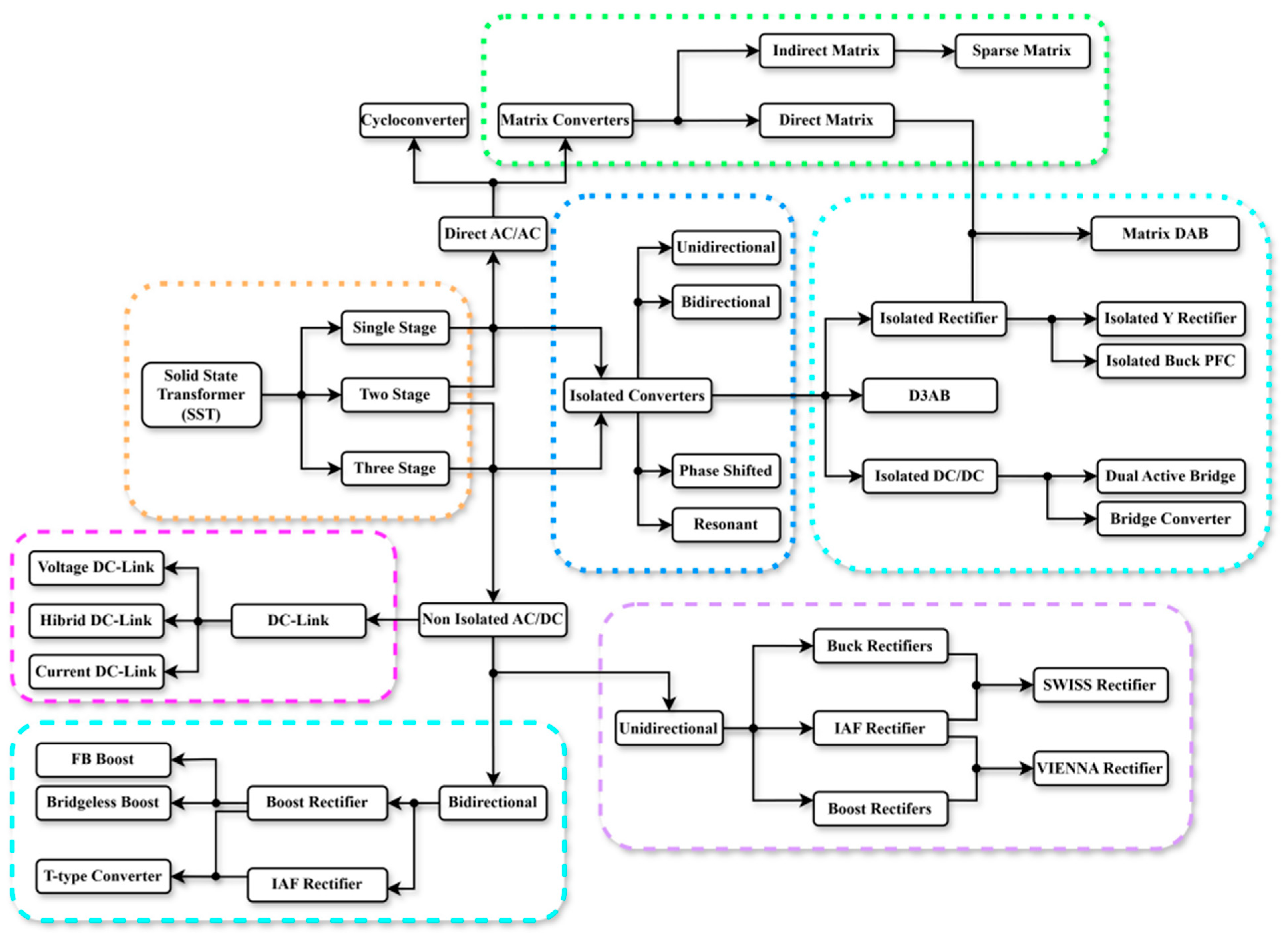
Representative SST technology baseline: In the LCA calculations, the SST is represented by a three-stage, isolated architecture (active AC–DC front-end, isolated DC–DC stage with a dual-active-bridge and a medium-frequency transformer, and a DC–AC inverter), which is widely reported in the SST literature and demonstrators [
32,
33]. The loss model uses aggregated efficiency values derived from typical stage efficiencies for this architecture; unless stated otherwise, the baseline assumes silicon IGBT-based power modules at medium voltage. Alternative device choices (SiC/GaN) and topologies (e.g., MMC-based SSTs) can shift both material intensity and efficiency and are therefore treated as a limitation and a topic for future work.
The same assumptions are intentionally applied to all transformer classes and both technologies to enable a controlled comparison. Their validity and influence are discussed in
Section 3.6 and explored quantitatively through the grid-emission-factor scenarios (see
Table 1) and the scenario sensitivity summary reported later in the manuscript; this highlights which conclusions are robust and which are sensitive to decarbonization and other uncertain parameters.
3.6. Treatment of Uncertainty and Limitations
Uncertainty is inherent in literature-based life cycle assessments due to variability in material inventories, manufacturing processes, operational conditions, and electricity-mix assumptions. In this study, uncertainty is addressed through explicit dispersion ranges and sensitivity scenarios rather than through a formal probabilistic LCA, which would require proprietary manufacturing data and long-term field measurements that are currently unavailable for multi-MVA SSTs.
Manufacturing and end-of-life CO
2 emissions are assumed to vary within ±15–25%, reflecting the spread reported in published transformer LCAs and recycling studies (e.g., Piotrowski and Markowska [
42]; Wang et al. [
44]). Operational-stage emissions are dominated by uncertainty in electricity grid CO
2 intensity and average loading conditions; this dominant source of variability is explored quantitatively through the defined grid-emission-factor scenarios and the associated sensitivity analysis presented later in the manuscript.
All transformer classes and both technologies are evaluated using identical assumptions for service life, operating hours, load factors, and system boundaries. This harmonized approach ensures internal consistency and enables meaningful comparison of results derived from heterogeneous literature sources. While absolute emission values should be interpreted as indicative, the direction and relative magnitude of the observed lifecycle CO2 differences are robust across the considered uncertainty ranges.
Several limitations remain. A uniform 25-year service life is assumed for both technologies, although power-electronic components in SSTs may require mid-life replacement. To reflect this, a conservative screening scenario is discussed in
Section 6, in which partial replacement of SST power-electronic modules is approximated as an additional manufacturing-stage burden. This approximation does not change the qualitative conclusions of the comparative assessment.
3.7. Consistency Checks and Qualitative Validation
Because this study is based on secondary LCA data and engineering loss models, validation is performed through consistency checks rather than new laboratory measurements. First, the selected no-load and load-loss parameters for line-frequency transformers are cross-checked against typical manufacturer datasheets and widely adopted efficiency requirements to ensure that values are within expected ranges for the respective power ratings. Second, the assumed SST efficiencies are benchmarked against reported efficiencies of published SST prototypes and demonstrator projects in comparable power ranges. Third, the resulting lifecycle stage shares (manufacturing vs. operation) are compared qualitatively with prior transformer LCAs, which commonly identify operation as the dominant contributor under today’s grid emission factors. These checks support the robustness of the order-of-magnitude comparison while the study remains explicitly indicative. For clarity,
Section 4 provides short, literature-referenced application context for the selected transformer classes, and
Section 5 then presents the quantified cradle-to-grave CO
2 results for each case study.
4. Technological Enablers and Use Cases in the Global Clean Energy Transition
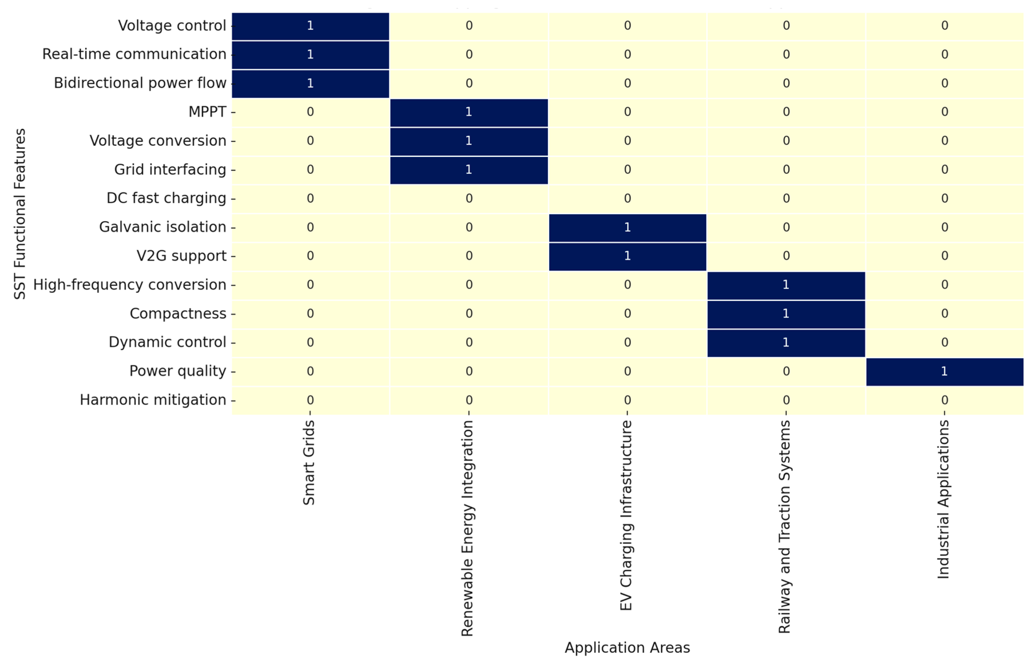
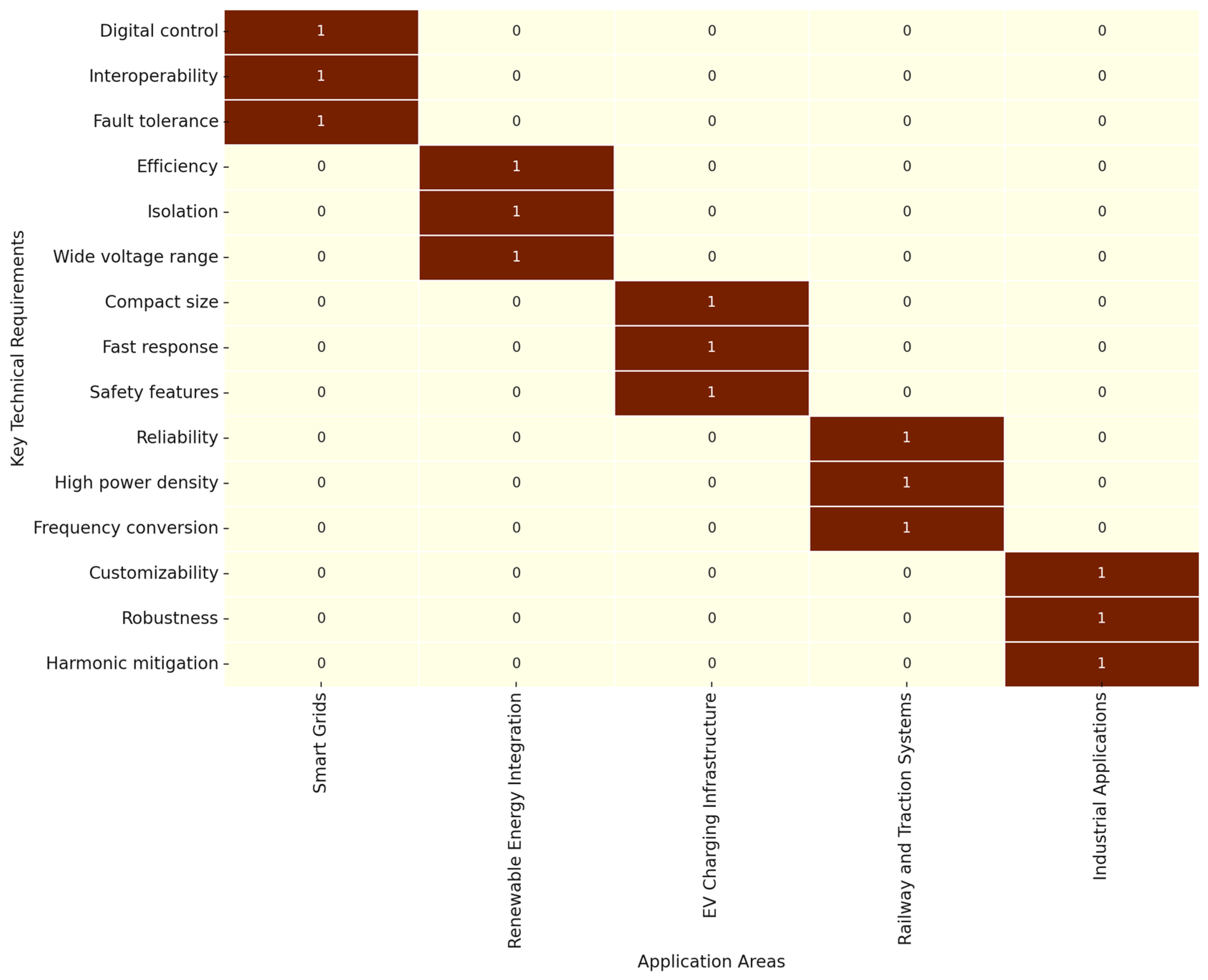
SSTs are being actively explored for modern power systems because their power-electronic structure can provide additional controllability and functional integration compared with conventional transformers, which is relevant to renewable integration, electric-vehicle infrastructure, and microgrid operation.
Wide-bandgap semiconductors such as silicon carbide (SiC) and gallium nitride (GaN) offer higher efficiency at elevated switching frequencies, enabling SSTs to operate with minimal energy loss and reduced physical dimensions. Despite their higher cost, these materials pave the way for compact and thermally efficient designs that outperform traditional transformers in high-performance settings. Complementing these semiconductors, advanced magnetic materials like amorphous and nanocrystalline alloys reduce core losses at high frequencies, making high-density and lightweight designs feasible. Combined with efficient thermal management strategies, these materials support sustained high-power operation.
The integration of digital control systems, often based on DSP or FPGA platforms, allows for real-time energy management, fault detection, and dynamic grid interaction. These systems also facilitate smart grid compatibility, enabling SSTs to interact with Internet of Things (IoT) platforms and AI-based forecasting tools. As a result, SSTs are ideally positioned for renewable energy systems, where they provide direct DC interfacing with solar arrays and battery storage units. Their ability to regulate voltage and suppress harmonics in real time supports the stable integration of intermittent sources. Examples of DSP/FPGA-based SST control implementations and reviews are provided in [
7,
11].
In electric vehicle (EV) charging infrastructure, SSTs offer compact and efficient medium-to-low voltage conversion, supporting ultra-fast charging and vehicle-to-grid (V2G) operations. Their bidirectional power flow capability further allows them to contribute to grid balancing efforts.
In microgrid and urban distribution networks, SSTs ensure voltage stability, enable islanded operation, and allow seamless reconnection to the main grid. Their compact footprint and controllable behavior enhance resilience in remote or high-density environments.
This combined technological and application-oriented perspective underscores the central role SSTs are poised to play in next-generation energy systems.
Table 2 compares the main characteristics of traditional transformers and SSTs, providing information on their technology, efficiency, dimensions, maintenance and applications. This comparison is intended to provide a better understanding of the advantages and limitations of both types of transformers and to assist in making informed decisions when selecting the appropriate solution for specific applications.
In summary, the comparison shows that SSTs offer many advantages over traditional transformers, such as higher energy efficiency, longer life, and a smaller environmental footprint. While SSTs can be more expensive to manufacture and are not always required in applications where conventional transformers are sufficient, they represent a highly promising technology for modern and sustainable energy grids.
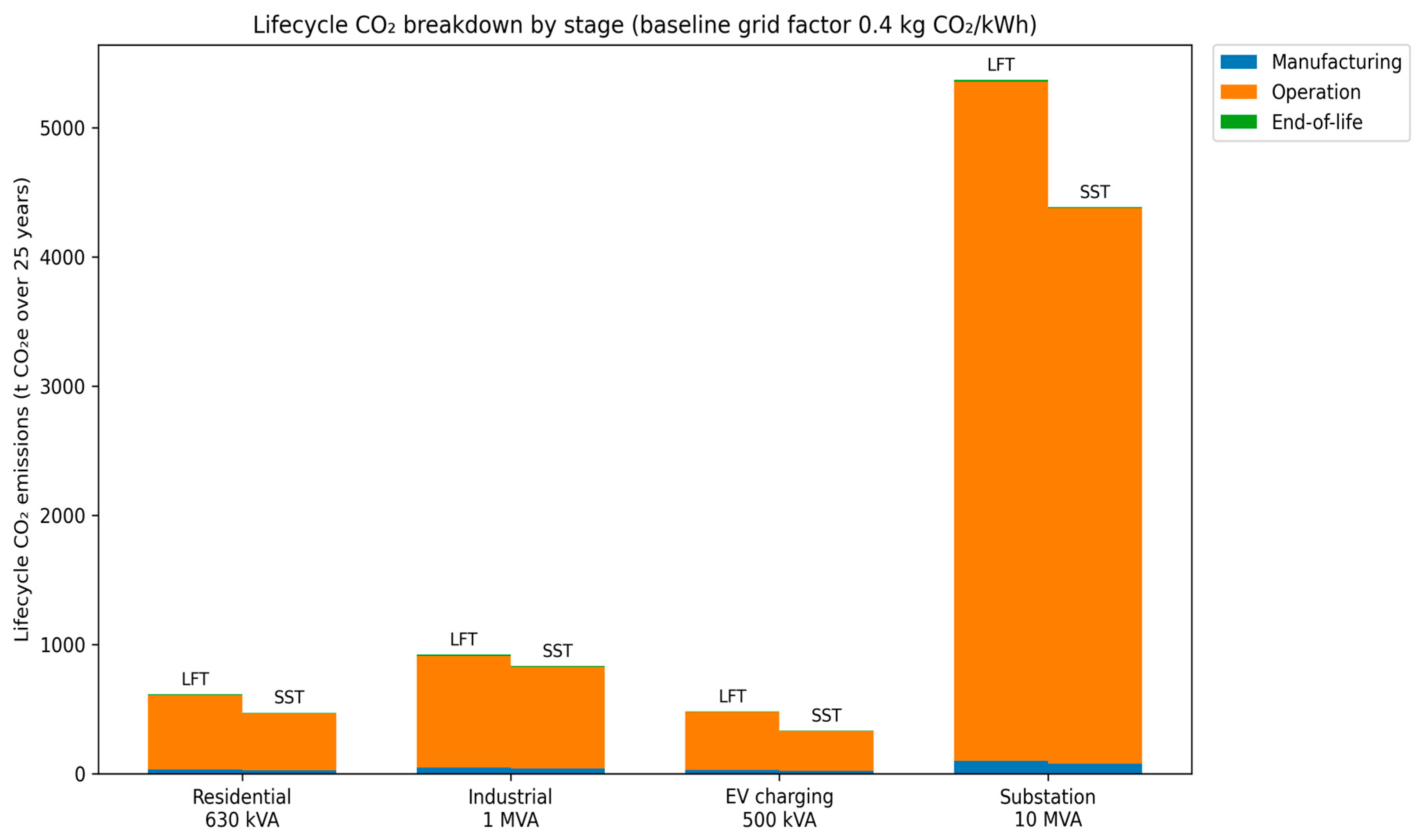
Figure 4 presents a lifecycle CO
2 breakdown (manufacturing, operation, and end-of-life) for conventional line-frequency transformers (LFTs) and solid-state transformers (SSTs) across the four case studies under the baseline assumptions.
The stacked bars highlight that operational losses dominate the total footprint in all cases; therefore, efficiency improvements drive most of the lifecycle CO
2 savings, while manufacturing and end-of-life contribute smaller shares. Values are based on the stage totals reported in
Table 3,
Table 4,
Table 5 and
Table 6.
SSTs enable a set of capabilities that are highly aligned with the structural requirements of the global clean energy transition. Unlike conventional line-frequency transformers, SSTs combine high-frequency conversion, bidirectional operation, advanced control functionalities, multiport interfacing, and deep integration with digital monitoring platforms. These attributes unlock new operational modes in distribution grids, transportation systems, industrial networks, and transmission–distribution boundaries.
This section presents four representative use cases, each illustrating a concrete decarbonization challenge and showing how SST deployment transforms technical limitations into opportunities for sustainable electrification.
4.1. Renewable-Rich Distribution Networks
Distribution networks with large shares of photovoltaics and wind generation face a series of structural challenges: voltage fluctuations caused by intermittent production, reverse power flows toward the substation, limited hosting capacity due to thermal and stability constraints, and increased harmonic distortion from inverter-based resources. Traditional MV/LV transformers are passive components with no controllability; they cannot regulate voltage dynamically, manage bidirectional flows, or coordinate distributed energy resources (DERs). Representative discussions of SST-enabled distribution flexibility and hybrid AC/DC feeder operation can be found in [
7,
11,
14].
SSTs fundamentally change this paradigm by combining high-frequency AC/DC and DC/AC stages with fast control loops capable of regulating voltage, frequency, power factor, and harmonic content in real time. Their millisecond-scale bandwidth allows them to follow renewable variability more effectively than tap-changers or capacitor banks. Moreover, their bidirectional power-flow capability enables controlled backfeeding of PV and battery storage upstream, improving the operational flexibility of feeders.
Several smart-grid and power-quality studies suggest that SST functionality (e.g., fast voltage support and harmonic mitigation) could improve the integration of variable renewables and enhance power quality in certain feeders. These system-level effects are beyond the direct quantitative scope of the present cradle-to-grave CO2 LCA; therefore, they are mentioned only for context and are not included in the reported lifecycle emission results.
From a decarbonization perspective, this use case highlights a direct opportunity: higher renewable penetration without extensive copper upgrades, lower grid losses, and enhanced stability—all essential features of a high-renewable energy system.
4.2. Smart Transportation and Fast-Charging Infrastructure
The rapid expansion of electric mobility introduces severe challenges for distribution and sub-transmission grids. Fast-charging stations (150–350 kW per charger) tend to create clustered peak loads, voltage sags, harmonics from power-electronic converters, and unbalanced phases when installed asymmetrically. Traditional transformers lack the control authority to mitigate these disturbances, and infrastructure reinforcement becomes expensive. Representative traction and extreme-fast-charging interface studies are discussed in [
18,
19].
SSTs offer a compact, high-performance solution for EV fast-charging hubs. Their high-frequency isolation and integrated AC/DC conversion enable direct medium-voltage to DC charging, eliminating multiple conversion stages and reducing system losses. Multiport SST architectures allow the integration of local energy storage, photovoltaics, and second-life batteries, smoothing the power demand seen by the grid.
Their bidirectional operation and precise control make advanced functionalities possible:
V2G operation for peak shaving and grid support;
buffered ultra-fast charging using local energy storage;
real-time harmonic mitigation;
adaptive current limiting during stressed network conditions.
These features can reduce grid congestion, enhance supply reliability, and minimize the carbon footprint of charging infrastructure by improving conversion efficiency and enabling local buffering (e.g., with on-site storage). The magnitude of such network-level benefits is highly site-specific and is therefore not quantified in this LCA-focused study.
Beyond charging efficiency, recent research on coupled electricity–transportation networks shows that coordinated restoration strategies leveraging building flexibility and electric-bus scheduling can enhance post-disaster resilience [
49]. While such resilience benefits are outside the quantitative boundary of the present LCA, SSTs can act as controllable interfaces at charging depots and distribution nodes, enabling bidirectional power flow and fast power-quality control that underpin such coordinated operation.
Thus, SST-enabled fast charging can be a promising option for improving the efficiency, controllability, and power-quality performance of charging infrastructure, which can support transport electrification in renewable-rich power systems.
4.3. Industrial and Commercial Power Networks
Industry is undergoing simultaneous electrification and digitalization, with increasing adoption of robotics, automation, variable-speed drives, data centers, and local renewable/ESS systems. These environments generate high harmonic content, fast load transients, and complex AC/DC interfacing requirements. Line-frequency transformers, even when combined with filters or static VAR compensators, cannot provide granular control or multiport energy management. SST roles in industrial/commercial power-quality conditioning and hybrid AC/DC distribution are reviewed in [
7,
11,
14].
SSTs deliver high controllability through programmable converters that independently regulate voltage, harmonics, phase imbalance, and power flow. In industrial microgrids, SSTs can unify AC and DC buses, enabling hybrid architectures where sensitive loads are connected to a regulated DC link, while legacy equipment remains on AC.
Their ability to perform real-time harmonic suppression, dynamic voltage restoration, and energy routing improves power quality and reduces equipment failures. Additionally, SSTs support predictive maintenance through continuous monitoring of thermal stress, semiconductor wear-out indicators, and harmonic signatures.
These capabilities improve energy efficiency, reduce operational emissions, and allow industries to integrate rooftop PV, battery storage, and waste-heat recovery systems more effectively. By reducing downtime and improving energy utilization, SSTs directly support industrial decarbonization and competitiveness.
4.4. Transmission–Distribution Interfaces and Smart Substations
At the boundary between transmission and distribution networks, operators face increasing complexity: variable renewable injections, bidirectional power flows, the rise of DERs, and new flexibility markets create operational uncertainties. Conventional power transformers provide no dynamic control, and their slow mechanical tap-changers are insufficient for managing modern fluctuations. Representative substation-scale SST concepts and demonstrators are discussed in [
7,
11,
21,
23].
SST-based smart substations introduce a new operational layer:
bidirectional active and reactive power control;
fast dynamic voltage support;
fault isolation using fast semiconductor switching;
seamless AC/DC interfacing for hybrid grids;
system reconfiguration during disturbances;
black-start and islanding capabilities.
These functionalities allow the T–D interface to absorb renewable fluctuations, coordinate local flexibility sources, and maintain stable operation even under high variability. SSTs also reduce copper losses and can operate in multiport configurations that connect MV AC, LV AC, MV DC, and LV DC simultaneously.
From a clean energy transition perspective, SSTs enable transmission operators to accommodate more renewable generation, integrate large-scale battery storage, and operate substations with a higher degree of automation and resilience. They also support new services such as grid-forming behavior and hybrid AC/DC operation, which are vital for future decentralized power systems.
In addition, SST functionalities can be relevant in remote or isolated multi-energy microgrids, where robust coordination between electrical and thermal subsystems is critical. For example, recent work on Antarctic unmanned observation stations demonstrates the value of electro-thermal coupling and distributionally robust optimisation to reduce carbon emissions under high renewable uncertainty [
50]. While our study does not model such hybrid microgrids quantitatively, SSTs can serve as controllable AC/DC interfaces in these architectures, suggesting an additional area for future lifecycle and resilience-oriented assessments.
5. Results
SSTs operate through a sequence of power-electronic conversion stages that fundamentally differ from the passive energy transfer mechanism of conventional line-frequency transformers. In typical SST architectures, the medium-voltage AC input is first converted to a controlled DC voltage through an active AC–DC conversion stage. This enables precise control of input current, power factor, and harmonic content, which directly influences operational losses and grid interaction. In this study, the SST is modelled as a representative three-stage isolated architecture as described in
Section 3.5, and the corresponding aggregated efficiency assumptions are applied consistently across all case studies.
The intermediate DC–DC conversion stage incorporates a high-frequency transformer that provides galvanic isolation and voltage adaptation. By shifting magnetic energy transfer to high switching frequencies, this stage enables substantial reductions in magnetic material volume and eliminates the need for oil-based insulation systems. At the same time, bidirectional power flow can be supported, allowing energy exchange between the grid, distributed generation, and storage systems.
On the output side, a DC–AC or DC conversion stage supplies regulated power to the load or downstream network. The combination of these stages allows SSTs to decouple input and output operating conditions, dynamically regulate voltage and power flow, and adapt to varying load profiles. From a lifecycle perspective, this operating principle leads to lower no-load and load-dependent losses, improved utilization under variable operating conditions, and reduced material intensity compared to conventional transformers.
The lifecycle assessment results presented in the following subsections reflect these fundamental operating characteristics by quantifying how differences in conversion stages, efficiency, and material composition translate into manufacturing, operational, and end-of-life CO2 emissions.
The electricity grid CO
2 intensity scenarios defined in
Table 1 are applied exclusively to the operational stage of the lifecycle, while manufacturing and end-of-life emissions are kept constant across all sensitivity cases.
5.1. Life Cycle of a Residential Transformer (630 kVA, 20 kV/0.4 kV)
Comparison between a classic transformer and a solid-state transformer.
Step 1: Manufacturing
Classic transformer: The manufacturing process involves making a magnetic core from laminated electrical steel, winding coils with a large amount of copper wire and filling it with transformer oil for cooling and insulation. For a 630 kVA transformer, between 800 and 1000 kg of copper and steel are used. The process of mining, refining and forming the metals themselves is very energy-intensive and results in the release of approximately 35 tons of CO2 even before the device is put into operation.
SST: The SST does not use a magnetic core and transformer oil, but instead includes power electronics (IGBT modules, DC links, filters) as well as active cooling systems (e.g., fans or liquid cooling). Although the production of electronic components has its own carbon footprint, it requires significantly less metal and allows for automated, modular production. The total CO2 emissions from the production process are estimated at approximately 25 tons of CO2, which is about 30% lower than the classical equivalent.
Stage 2: Operation
Classical transformer: During operation, the classical transformer has constant losses—both idle losses (about 1.1 kW) and load losses (about 5.4 kW). This results in an average of 57,240 kWh of energy losses per year, which, with a standard energy mix (0.4 kg CO2/kWh), means 22.9 tons of CO2 emissions per year. Over 25 years of operation, this accumulates approximately 572 tons of CO2.
SST: Due to its higher efficiency (~99.2%), the SST has average losses of about 5.04 kW or 44,150 kWh per year. This results in annual emissions of about 17.7 tons of CO2. Over the same 25-year period, this amounts to around 442 tonnes of CO2, which is 130 tonnes less than a conventional transformer.
Stage 3: Recycling and end of life
Conventional transformer: At the end of its life, the transformer must be dismantled and the oil treated as hazardous waste. Recycling of metals is possible, but often incomplete due to embedded components and aging of materials. Total emissions associated with decommissioning, transport, treatment and partial recycling are estimated at 5–10 tonnes of CO2.
SST: The SST is built modularly, with clearly separable components (electronics, housing, cooling), which facilitates recycling. Although e-waste requires specific treatment, there are well-developed systems for recycling aluminium and electronics. The end-of-life stage results in approximately 5 tonnes of CO2.
Table 3 presents a comparative analysis of the total carbon footprint generated by a traditional oil-filled transformer and a modern SST over their full lifecycle. The assessment is divided into three key stages: manufacturing, operational use over a standard service life of 25 years, and end-of-life disposal and recycling. Each stage includes estimates of CO
2 emissions based on typical material usage, energy losses, and handling processes. The SST demonstrates a significant advantage in reducing environmental impact, especially in long-term operation and recyclability, making it a more sustainable solution for modern power distribution systems.
Table 3.
Lifecycle CO2 Emissions Comparison: Traditional Transformer vs. SST (630 kVA, 20 kV/0.4 kV).
Table 3.
Lifecycle CO2 Emissions Comparison: Traditional Transformer vs. SST (630 kVA, 20 kV/0.4 kV).
| Lifecycle Stage | Traditional Transformer | Solid-State Transformer | Notes | Primary Data Source (Reference) |
|---|
| Manufacturing | ~35 t CO2 | ~25 t CO2 | Steel, copper and oil vs. power electronics and modular cooling | [42,44,46] |
| Operation (25 years) | ~572 t CO2 (22.9 t/year) | ~442 t CO2 (17.7 t/year) | Calculated from no-load and load losses | [42,44] |
| Annual energy losses | ~57,240 kWh | ~44,150 kWh | Based on 8760 h/year operation | Derived in this study |
| End-of-life | ~5–10 t CO2 | ~5 t CO2 | Oil treatment vs. modular electronics recycling | [45,46] |
| Total lifecycle emissions | ~610–620 t CO2 | ~470 t CO2 | Aggregated lifecycle total | This study (derived) |
Table 3 summarizes the lifecycle CO
2 emissions of a conventional oil-filled transformer and an SST for a representative 630 kVA distribution application. Manufacturing-stage values are derived from published transformer LCA studies and reflect differences in material intensity and the absence of insulating oil in the SST. Operational emissions are calculated using harmonized loss models and identical operating assumptions, following the approach commonly adopted in transformer LCAs [
42,
44]. End-of-life impacts are based on literature-reported recycling and disposal scenarios. The table shows that operational losses dominate the total lifecycle footprint, while improved efficiency leads to a net reduction of approximately 140–150 t CO
2 over a 25-year service life for the SST case.
5.2. Life Cycle of an Industrial Transformer for a Small Factory (1 MVA, 20 kV/0.4 kV)
Step 1: Manufacturing
Classic transformer: A traditional 1 MVA transformer requires large laminated steel cores, extensive copper windings, and significant amounts of transformer oil. The typical raw material mass exceeds 1500 kg. The processes of mining, processing, assembly, and insulation add up to approximately 50 tons of CO2 emissions during production.
SST: The SST version includes high-power IGBT modules, advanced converters, and active thermal management systems. Despite using more electronics, it reduces dependence on heavy materials. Automated assembly and modular design result in an estimated ~40 tons of CO2 during manufacturing.
Step 2: Operation
Classic transformer: With typical idle and load losses of ~9.8 kW, the traditional transformer consumes about 86,328 kWh/year, generating 34.5 tons of CO2 annually. Over 25 years, this amounts to ~862 tons of CO2.
SST: The SST, with ~99.1% efficiency, has average losses of 9 kW, consuming about 78,840 kWh/year. This equates to 31.5 tons of CO2 annually, or ~787 tons over 25 years, yielding a savings of ~75 tons of CO2 in this stage alone.
Step 3: Recycling and End of Life
Classic transformer: Handling and recycling a large oil-filled unit is resource-intensive due to the hazardous nature of the oil and the mass of metals. The recycling-related emissions are estimated at ~10 tons of CO2.
SST: SSTs are modular, allowing easier material separation and recycling. E-waste management systems are better adapted to electronics and aluminium components. The total end-of-life impact is estimated at ~5 tons of CO2.
Table 4 presents a full lifecycle carbon emissions comparison between a traditional oil-filled transformer and an SST designed for industrial applications with a 1 MVA power rating. The assessment includes emissions from manufacturing, 25 years of operation, and end-of-life recycling. SSTs offer improved efficiency and modularity, leading to substantial CO
2 savings.
Table 4.
Lifecycle CO2 Emissions Comparison: Industrial Transformer (1 MVA, 20 kV/0.4 kV).
Table 4.
Lifecycle CO2 Emissions Comparison: Industrial Transformer (1 MVA, 20 kV/0.4 kV).
| Lifecycle Stage | Traditional Transformer | Solid-State Transformer | Notes | Primary Data Source (Reference) |
|---|
| Manufacturing | ~50 t CO2 | ~40 t CO2 | Larger steel and copper mass vs. power electronics | [42,44,46] |
| Operation (25 years) | ~862 t CO2 (34.5 t/year) | ~787 t CO2 (31.5 t/year) | Calculated from no-load and load losses | [42,44] |
| Annual energy losses | ~86,328 kWh | ~78,840 kWh | Based on 8760 h/year operation | Derived in this study |
| End-of-life | ~10 t CO2 | ~5 t CO2 | Oil handling vs. modular electronics recycling | [45,46] |
| Total lifecycle emissions | ~922 t CO2 | ~832 t CO2 | Aggregated lifecycle total | This study (derived) |
Table 4 presents the lifecycle CO
2 emissions of a conventional and an SST for a representative 1 MVA industrial distribution application. Manufacturing-stage emissions are higher than in the residential case due to increased material intensity, particularly steel and copper, while SST manufacturing benefits from reduced magnetic material and oil-free design. Operational emissions remain the dominant contributor to total lifecycle impact and are calculated using harmonized loss assumptions consistent with published transformer LCAs [
42,
44]. As shown, the SST achieves a net lifecycle reduction of approximately 90 t CO
2 over a 25-year service life, primarily driven by improved conversion efficiency.
5.3. Life Cycle of a Transformer for EV Charging Station (500 kVA, 20 kV/0.4 kV)
Step 1: Manufacturing
Classic transformer: A 500 kVA traditional transformer uses several hundred kilograms of copper and steel, along with transformer oil for cooling and insulation. The manufacturing process includes lamination of the core, winding of copper conductors, and sealing of the oil tank. Total emissions from raw material extraction and production are approximately 30 tons of CO2.
SST: The SST variant for the same power rating uses compact power electronics, lightweight aluminium housings, and integrated cooling systems. Due to less reliance on heavy metals and more streamlined modular design, production emissions are estimated at ~22 tons of CO2.
Step 2: Operation
Classic transformer: With average no-load and load losses totaling ~5.1 kW, the classic unit consumes around 44,676 kWh/year, which corresponds to 17.9 tons of CO2 annually (based on 0.4 kg CO2/kWh). Over 25 years, this equals ~448 tons of CO2.
SST: Thanks to its efficiency (~99.3%), the SST reduces losses to about 3.5 kW on average, or 30,660 kWh/year, equivalent to 12.3 tons of CO2/year. Over 25 years, this adds up to ~308 tons of CO2, saving approximately 140 tons in this stage alone.
Step 3: Recycling and End of Life
Classic transformer: Recycling this type of unit involves removing and disposing of oil and separating metal components. Due to complexity, total end-of-life CO2 emissions are estimated at ~6 tons.
SST: The SST’s modular design allows easier disassembly, with standardised aluminium, PCBs, and cooling units. E-waste is treated separately, resulting in an end-of-life footprint of ~4 tons of CO2.
The following
Table 5 provides a comparative analysis of CO
2 emissions across the full lifecycle of a traditional oil-filled transformer and an SST used for a 500 kVA EV charging station. The analysis covers three key lifecycle stages: manufacturing, operation over 25 years, and end-of-life recycling. The SST offers superior performance in all stages, resulting in a significantly lower total carbon footprint.
Table 5.
Lifecycle CO2 Emissions Comparison: Transformer for EV Fast-Charging Station (500 kVA, 20 kV/0.4 kV).
Table 5.
Lifecycle CO2 Emissions Comparison: Transformer for EV Fast-Charging Station (500 kVA, 20 kV/0.4 kV).
| Lifecycle Stage | Traditional Transformer | Solid-State Transformer | Notes | Primary Data Source (Reference) |
|---|
| Manufacturing | ~30 t CO2 | ~22 t CO2 | Reduced metal mass and oil-free SST design | [42,44,46] |
| Operation (25 years) | ~448 t CO2 (17.9 t/year) | ~308 t CO2 (12.3 t/year) | Calculated from no-load and load losses | [42,44] |
| Annual energy losses | ~44,676 kWh | ~30,660 kWh | Based on 8760 h/year operation | Derived in this study |
| End-of-life | ~6 t CO2 | ~4 t CO2 | Oil treatment vs. modular electronics recycling | [45,46] |
| Total lifecycle emissions | ~484 t CO2 | ~334 t CO2 | Aggregated lifecycle total | This study (derived) |
Table 5 reports the lifecycle CO
2 emissions associated with a conventional transformer and an SST used in a 500 kVA EV fast-charging station. This application is characterized by highly variable and peaky load profiles; however, for comparability, both technologies are evaluated under identical average operating assumptions. Manufacturing-stage emissions reflect the reduced material intensity and oil-free design of the SST, while operational emissions dominate the total lifecycle footprint. Due to improved efficiency under continuous operation, the SST achieves an indicative lifecycle CO
2 reduction of approximately 150 t over a 25-year service life, consistent with trends reported in recent transformer LCA studies [
42,
44].
5.4. Life Cycle of a Substation Transformer (10 MVA, 110 kV/20 kV)
Such a transformer is a key component in power distribution substations—an intermediate link between the high-voltage transmission network and the medium-voltage distribution network. High power (10 MVA) means large volumes of transferred energy and potentially much higher energy losses, respectively, a greater significance for the carbon footprint. It is used in urban and industrial areas, as well as for powering clusters of EV charging stations, logistics parks, or manufacturing areas.
Step 1: Manufacturing
Classic transformer: A 10 MVA oil-filled transformer is a large and heavy unit requiring several tons of laminated steel, copper windings, and substantial amounts of transformer oil. The entire manufacturing process, from mining to assembly, results in an estimated ~100 tons of CO2 emissions due to the energy-intensive nature of material extraction and processing.
SST: The SST alternative for this power range integrates multiple high-voltage electronic conversion stages with active cooling and modular packaging. Although electronics and thermal systems add complexity, SSTs use less metal overall and benefit from factory automation. The total production emissions are estimated at ~80 tons of CO2.
Step 2: Operation
Classic transformer: In typical 24/7 grid service, the classic unit suffers average losses of ~60 kW (i.e., on the order of tens of kW for a 10 MVA-class transformer). Over 25 years (8760 h/year), this equates to 13.14 GWh of lost energy. At 0.4 kg CO2 per kWh, operational emissions total ~5256 tons of CO2.
SST: Thanks to higher efficiency (~99.3%), the SST loses less energy—about 49 kW on average—resulting in 10.73 GWh of losses over 25 years, or ~4292 tons of CO2. This represents a savings of ~964 tons in the operational stage.
Step 3: Recycling and End of Life
Classic transformer: End-of-life involves draining and processing large volumes of hazardous oil and handling heavy steel cores and copper. Recycling-related emissions are estimated at ~15 tons of CO2.
SST: The modular construction allows easier separation of power modules, aluminium housings, and standardised electronic components. Despite the e-waste treatment requirements, total emissions at this stage are estimated at ~8 tons of CO2.
Table 6 summarizes the estimated carbon footprint of a traditional oil-filled transformer and a modern SST over a 25-year lifecycle in a high-power substation application. It includes emissions from manufacturing, operation, and end-of-life recycling. The SST demonstrates a notable reduction in emissions due to improved efficiency and modular design.
Table 6.
Lifecycle CO2 Emissions Comparison: Substation Transformer (10 MVA, 110 kV/20 kV).
Table 6.
Lifecycle CO2 Emissions Comparison: Substation Transformer (10 MVA, 110 kV/20 kV).
| Lifecycle Stage | Traditional Transformer | Solid-State Transformer (SST) | Notes | Primary Data Source (Reference) |
|---|
| Manufacturing | ~100 t CO2 | ~80 t CO2 | Large steel and copper mass vs. modular power electronics | [42,44,46] |
| Operation (25 years) | ~5256 t CO2 (13.14 GWh) | ~4292 t CO2 (10.73 GWh) | Calculated from average losses at rated service | [42,44] |
| Annual energy losses | ~525,600 kWh | ~429,240 kWh | Based on 8760 h/year operation | Derived in this study |
| End-of-life | ~15 t CO2 | ~8 t CO2 | Oil treatment vs. modular electronics recycling | [45,46] |
| Total lifecycle emissions | ~5371 t CO2 | ~4380 t CO2 | Aggregated lifecycle total | This study (derived) |
Table 6 presents the lifecycle CO
2 emissions of a conventional oil-filled transformer and an SST for a 10 MVA transmission–distribution interface substation. Due to the high power throughput, operational losses dominate the lifecycle footprint of both technologies, accounting for more than 95% of total emissions. Manufacturing-stage emissions are higher in absolute terms compared to lower-power cases, reflecting the large material mass of substation-class equipment. Under identical operating assumptions, the SST achieves an indicative lifecycle CO
2 reduction of approximately 1000 t over a 25-year service life, illustrating how even modest efficiency improvements translate into large absolute emission savings at high power ratings.
Table 3,
Table 4,
Table 5 and
Table 6 collectively demonstrate the lifecycle CO
2 performance of conventional line-frequency transformers and SSTs across a wide power range and representative application contexts. Although absolute emission values scale strongly with power rating and energy throughput, a consistent pattern emerges: operational losses dominate the total lifecycle footprint in all cases, while SSTs systematically achieve lower lifecycle emissions under identical assumptions. The relative magnitude of the reduction varies with loading and application, but the direction of the effect remains robust, indicating that improved conversion efficiency and reduced material intensity are the primary drivers of the observed CO
2 savings. These results provide a consistent, literature-aligned basis for the comparative discussion and sensitivity analysis presented in the following sections.
6. Discussion: System-Level Impact, Carbon Reduction, and Deployment Pathways
The results presented in
Section 5 demonstrate that SSTs provide consistent and measurable lifecycle advantages across residential, industrial, EV-charging, and substation applications. While individual numerical values vary depending on power rating and loading conditions, several cross-cutting observations emerge that clarify the role of SSTs in the global clean energy transition and their long-term sustainability potential.
6.1. Carbon Footprint Reduction and Energy Efficiency Trends
Across the distribution-scale case studies (0.5–1 MVA), SSTs deliver a total lifecycle CO2 reduction of roughly 90–150 tons compared to conventional oil-filled transformers. For the 10 MVA substation case, the absolute reduction is much larger (≈1000 tons), reflecting the higher lifetime energy throughput. These savings originate primarily from:
Higher operating efficiency, which reduces lifetime energy losses by approximately 9–31% across the studied cases (
Table 3,
Table 4,
Table 5 and
Table 6).
Lower idle losses, especially relevant in lightly loaded or intermittently used networks.
Reduced material intensity during manufacturing, due to the absence of heavy magnetic cores and transformer oil.
More efficient end-of-life processing, owing to modular construction and reduced hazardous waste.
Operational losses dominate the lifecycle footprint of both technologies. Therefore, even modest improvements in conversion efficiency—on the order of 0.2–0.4%—produce large cumulative CO2 benefits over a 25-year service life. This aligns SST adoption with mandatory energy-efficiency targets under European Ecodesign regulations and with national decarbonization policies in many countries.
The numerical results confirm that SSTs act as system-level efficiency multipliers: their benefits accumulate not only at the device level but across entire distribution networks.
The values include manufacturing, 25-year operational losses, and end-of-life treatment. SSTs consistently demonstrate lower total emissions due to reduced losses, lower material intensity, and improved recyclability. The absolute savings are on the order of 90–150 t CO2 for distribution-scale units (0.5–1 MVA) and ~1000 t CO2 for the 10 MVA substation case.
Table 7 presents a summary of lifecycle CO
2 emissions for four representative transformer categories. Values include manufacturing, 25-year operational losses, and end-of-life treatment. SSTs consistently demonstrate lower total emissions due to reduced losses, lower material intensity, and improved recyclability. The relative reduction is calculated as (CF
LFT − CF
SST)/CF
LFT × 100%, yielding approximately 24%, 10%, 31%, and 18% reductions for the 630 kVA, 1 MVA, 500 kVA, and 10 MVA cases, respectively.
As shown in
Table 7, SSTs reduce total lifecycle CO
2 emissions by approximately 90–150 t CO
2 for the distribution-scale units considered here, while the 10 MVA substation case shows nearly 1000 t CO
2 savings due to the much larger lifetime energy throughput.
Sensitivity to electricity CO
2 intensity: since operational emissions scale linearly with the electricity-mix emission factor, the absolute lifecycle CO
2 savings are recalculated for the scenarios in
Table 1a by scaling only the operational stage (manufacturing and end-of-life kept unchanged). The resulting absolute lifecycle CO
2 savings for each application and electricity-mix scenario are reported explicitly in
Table 7a.
These ranges capture the dominant operational-stage sensitivity to the electricity mix. Applying the ±15–25% manufacturing and end-of-life bounds in
Section 3.6 introduces an additional (smaller) spread in absolute savings (typically on the order of ±(5–20) t CO
2 for the distribution/EV cases and ±(50–200) t CO
2 for the 10 MVA case), without changing the qualitative conclusion that SSTs reduce lifecycle CO
2 under the assumed operating profiles.
Under the decarbonization pathway (avg EF ≈ 0.25), absolute lifecycle savings decrease by about 35–40% relative to the baseline (EF = 0.40). For example, savings drop from ~150 t to ~98 t for the 500 kVA EV case and from ~991 t to ~630 t for the 10 MVA substation case.
6.2. Flexibility and Renewable Integration Advantages
Beyond improving energy efficiency, SSTs introduce operational capabilities that fundamentally expand the flexibility of distribution networks. Unlike conventional transformers, SSTs support fully bidirectional power flow, a prerequisite for large-scale photovoltaic integration and for future prosumer-driven distribution architectures. Their dynamic voltage and reactive-power control capabilities enable rapid compensation of voltage deviations and maintain stability in feeders exposed to high solar or wind variability. High-frequency isolation reduces the physical footprint and allows fast-acting control loops, while embedded sensing and monitoring functions provide continuous visibility into component health, loading conditions, and power quality. Because SSTs are built from modular power-electronic stages, they also enable staged upgrades and replacements—helping utilities extend asset life without wholesale system shutdowns.
In the context of the global clean energy transition, these functionalities directly address long-standing technical constraints such as hosting-capacity limits, congestion caused by variable renewable generation, and complex coordination of distributed resources. SSTs therefore act not merely as replacement equipment, but as system-level flexibility assets that enhance the controllability, resilience, and adaptability of modern distribution networks.
6.3. Economic and Practical Deployment Considerations
While SSTs offer clear technical advantages, their adoption depends on economic viability and practical deployment constraints. The initial capital expenditure remains higher than that of conventional transformers, primarily due to the cost of power semiconductors, cooling systems, and advanced digital controllers. However, operational expenditures are significantly lower because SSTs reduce conversion losses, eliminate oil handling, and enable predictive maintenance through integrated monitoring. Their modular design also allows for targeted replacement of subassemblies—such as DC–DC stages or control boards—reducing downtime and lowering long-term maintenance costs. Furthermore, the reduced size and weight of SST units create advantages in installations with limited space, including urban substations, EV charging depots, and containerized modular grids.
From a cost–benefit perspective, SSTs become economically favorable in environments with high utilization, rapidly fluctuating loads, or stringent power-quality requirements. Industrial feeders, fast-charging stations, and commercial buildings stand to benefit most, as the operational savings and performance improvements can compensate for the higher upfront investment over the asset lifetime.
To provide a simple techno-economic indicator linked directly to the LCA results, we estimate the present-value (PV) cost of avoided loss-related electricity consumption as:
where c_el is the electricity price, r is the discount rate, and N is the service life. Using the annual loss reductions from
Table 3,
Table 4,
Table 5 and
Table 6 (≈10.5, 7.8, 14.9, and 96.4 MWh·y
−1 for the 630 kVA, 1 MVA, 500 kVA, and 10 MVA cases) and illustrative values c_el = 0.1 €/kWh, r = 5%, and N = 25 years, the PV OPEX savings are ≈15 k€, ≈11 k€, ≈21 k€, and ≈136 k€, respectively. These indicative values suggest that efficiency-driven OPEX savings alone may not fully offset the current SST CAPEX premium, and that additional grid-service value streams (e.g., power-quality support and controllability) can be important in practical investment decisions.
6.4. Lifecycle Sustainability and Circularity
A distinguishing feature of SSTs is their alignment with circular-economy principles. In contrast to oil-filled transformers built from heavy steel cores, large volumes of copper, and mineral oil, SSTs employ lighter aluminium housings, minimal copper, and no liquid insulation. Their modular architecture improves the recoverability of PCBs, semiconductors, and mechanical structures at the end of life. The elimination of transformer oil not only reduces the carbon footprint of manufacturing but also removes the need for hazardous-waste processing and eliminates environmental risks associated with leakage and flammability.
Lifecycle assessment indicates that the manufacturing stage contributes only 15–20% of total emissions for both technologies; therefore, the superior operational efficiency of SSTs is the dominant factor behind their reduced lifecycle CO2 footprint. This observation reinforces the relevance of SSTs to clean-energy-transition policies aimed at reducing distribution losses and improving overall electricity-system efficiency.
6.5. System-Level Role in the Clean Energy Transition
SSTs do not merely replace conventional transformers—they fundamentally reshape the functional boundaries of distribution networks. Their capabilities make them enabling technologies for renewable-rich grids, high-power EV charging corridors, hybrid AC/DC distribution architectures, and intelligent commercial or industrial campuses. SSTs can reduce feeder losses, enhance local power quality, mitigate congestion caused by distributed generation, and facilitate coordinated control of distributed energy resources.
By integrating controllability, sensing, and bidirectional power flow into a single device, SSTs can support the transition toward more electrified, digitalized, and resilient distribution infrastructures, particularly in applications where controllability and power quality are valued alongside efficiency.
6.6. Limitations and Future Research Needs
Despite their strong technical and environmental potential, several limitations must be addressed before SSTs achieve widespread deployment. The most significant barrier remains the high cost of power-electronic devices, particularly for medium-voltage applications. Thermal management challenges persist, especially under high-load transients, while ensuring the long-term reliability of semiconductor devices remains an active research area. Harmonic emissions require high-quality filtering solutions, and existing grid codes—designed for passive transformers—do not yet fully accommodate the operational characteristics of SSTs. Furthermore, large-scale field demonstrations at multi-MVA ratings are still limited, leaving uncertainty around long-term operational performance.
Future research should therefore focus on improving multi-cell topologies, enhancing cooling through integrated heat pipes or liquid systems, and developing advanced control algorithms with predictive and adaptive capabilities. Optimization of SiC and GaN devices for medium-voltage stages, together with the integration of digital twins for real-time monitoring and prognostics, represents a promising pathway for the next generation of SST systems.
6.7. Summary of the Discussion
The analysis indicates that SSTs can act as enabling technologies for more efficient and controllable electricity networks, combining higher conversion efficiency with advanced control functionality and oil-free designs. However, the present results are literature-based and indicative, and they should be interpreted as screening evidence rather than as predictive, site-specific quantification. Continued work is needed on field validation, reliability, and refined lifecycle inventories for emerging multi-MVA SST designs.
7. Conclusions
SSTs are increasingly investigated as a potential enabling technology for next-generation power systems, since they combine power-electronic conversion, high-frequency isolation, and advanced digital control functionalities that are not available in conventional line-frequency transformers.
This paper presented a structured, comparative life cycle assessment (LCA) of conventional transformers and SSTs across four representative application contexts: residential distribution networks, industrial distribution systems, electric vehicle fast-charging infrastructure, and transmission–distribution interface substations. The analysis was conducted using literature-derived data, manufacturer specifications, and harmonized assumptions applied consistently across all cases, with a cradle-to-grave system boundary covering manufacturing, operation, and end-of-life stages.
The results indicate that, under identical assumptions, SST-based solutions are associated with indicative lifecycle CO2 emission reductions on the order of approximately 10–30% compared to conventional transformers. These reductions are primarily driven by lower operational losses and, to a lesser extent, by reduced material intensity and improved end-of-life handling enabled by modular, oil-free designs. While the magnitude of the reduction varies with power rating and operating profile, the comparative trend remains consistent across all analyzed cases.
Beyond lifecycle emissions, the paper briefly discusses system-level capabilities that are often associated with SST deployment (e.g., bidirectional operation, fast voltage and power control, and compatibility with hybrid AC/DC architectures). These aspects are not quantified within the present CO2-focused LCA scope, but they provide additional context for why SSTs are being explored in renewable-rich distribution networks, electrified transport corridors, and future flexible substations.
At the same time, several limitations must be acknowledged. The results are based on literature-derived estimates and representative assumptions rather than site-specific operational data. A uniform service life of 25 years was assumed for both transformer technologies; however, SSTs may require mid-life replacement of power-electronic components, and a conservative replacement sensitivity is discussed in
Section 3.6. In addition, the operational results depend on representative load factors and electricity-mix assumptions, which are explored through the grid-emission-factor scenarios reported in
Section 5 and
Section 6.
Overall, the findings suggest that SSTs constitute a relevant enabling technology for future low-carbon power systems when evaluated from a lifecycle perspective. However, the results should be interpreted as indicative rather than predictive. Future research should focus on large-scale field demonstrations, long-term reliability data for power-electronic components, and refined lifecycle assessments that incorporate detailed operational profiles, component replacement strategies, and evolving electricity-generation mixes. Although the presented results are based on literature-derived data and screening-level assumptions, the applied dispersion ranges and electricity-mix sensitivity scenarios indicate that the comparative conclusion—lower lifecycle CO2 emissions for SSTs compared to conventional transformers—remains robust across realistic parameter variability.