A Benchmark System for Verifying the Harmonic Amplification Mechanism of Wideband Oscillations


Abstract
1. Introduction
2. Theoretical Foundation of the Harmonic Amplification Mechanism for Wideband Oscillations
2.1. Two Kinds of Wideband Converter Models
2.2. The Applicability of the Positive Sequence Grid Model for Harmonic Amplification Analysis
2.3. Consistency Between Network Resonance Modes and Eigenvalues of the System State Equations
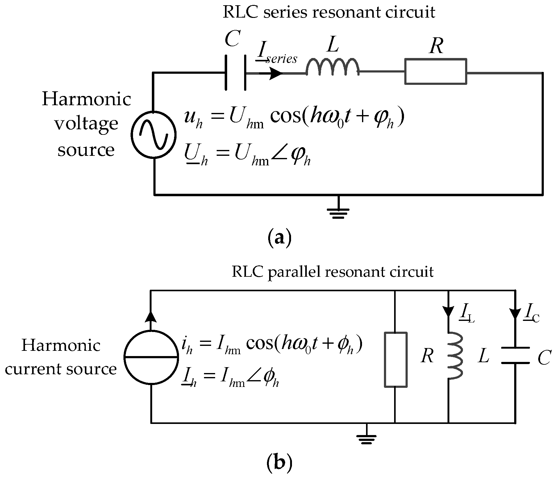
2.4. Inverse Relationship Between Resonant Peak Voltage and Modal Damping Ratio
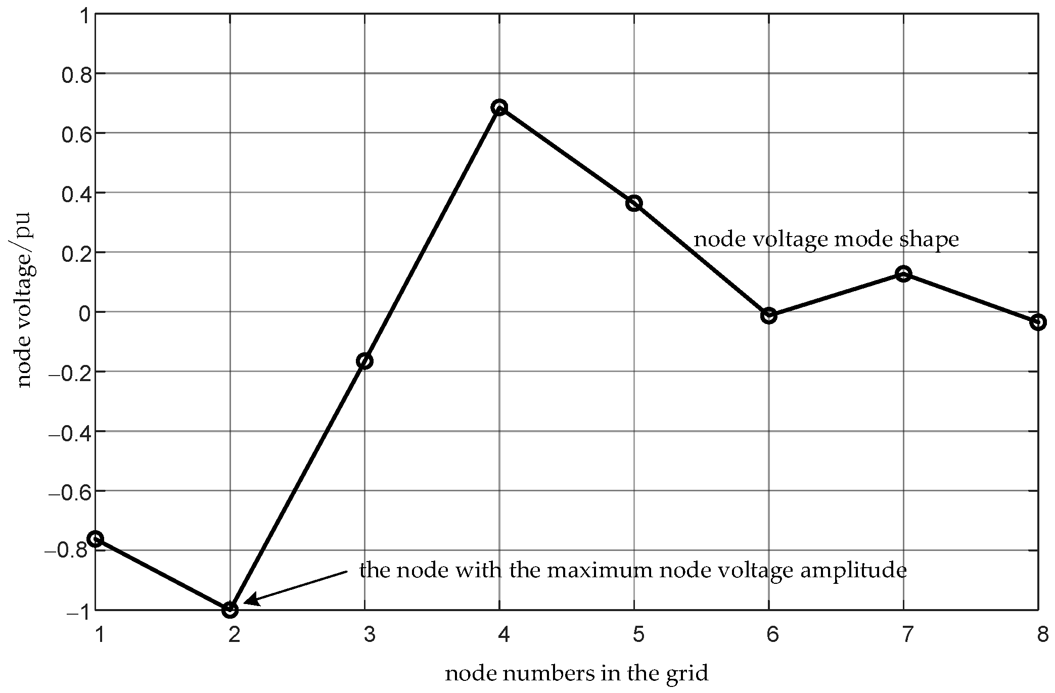
2.5. Physical Meaning of Node Voltage Mode Shapes and Resonant Peak Voltages
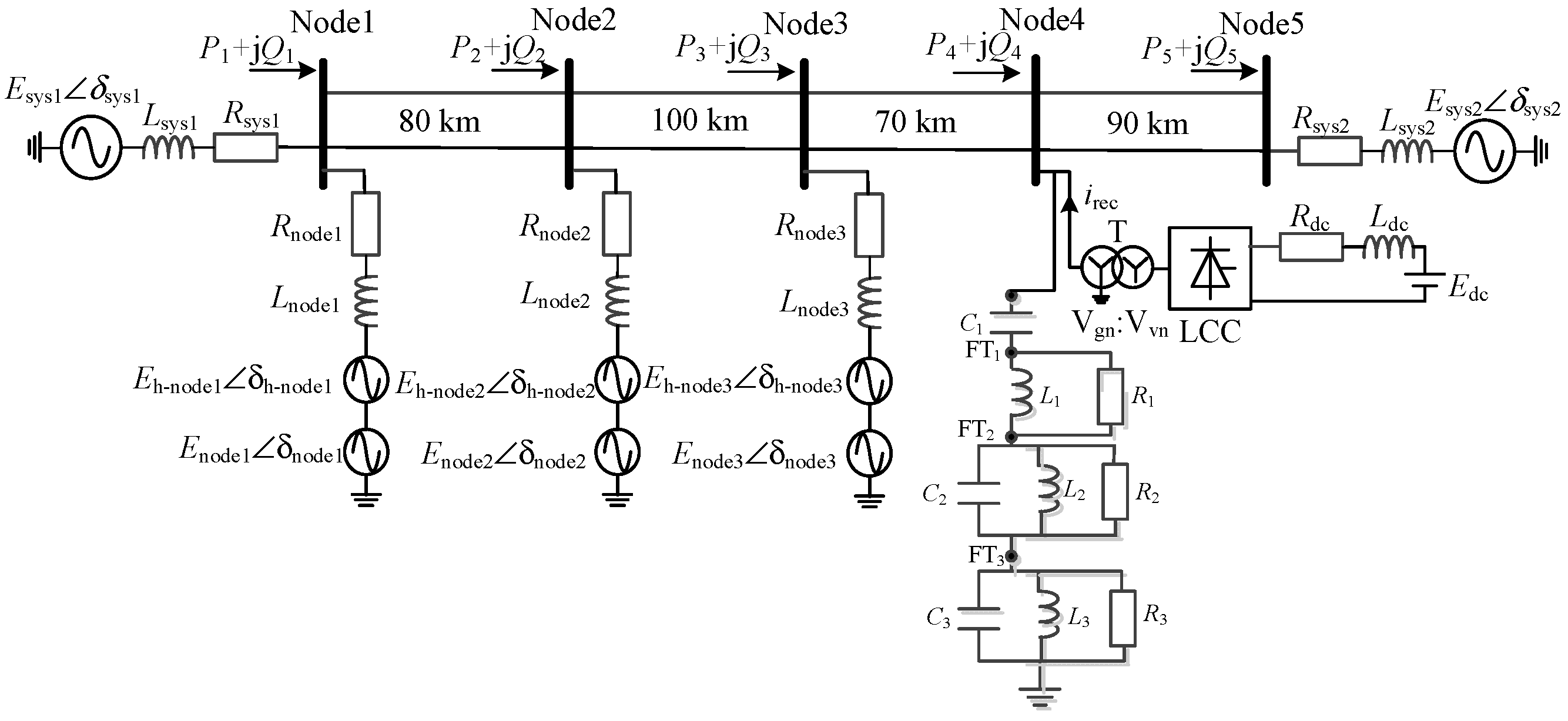
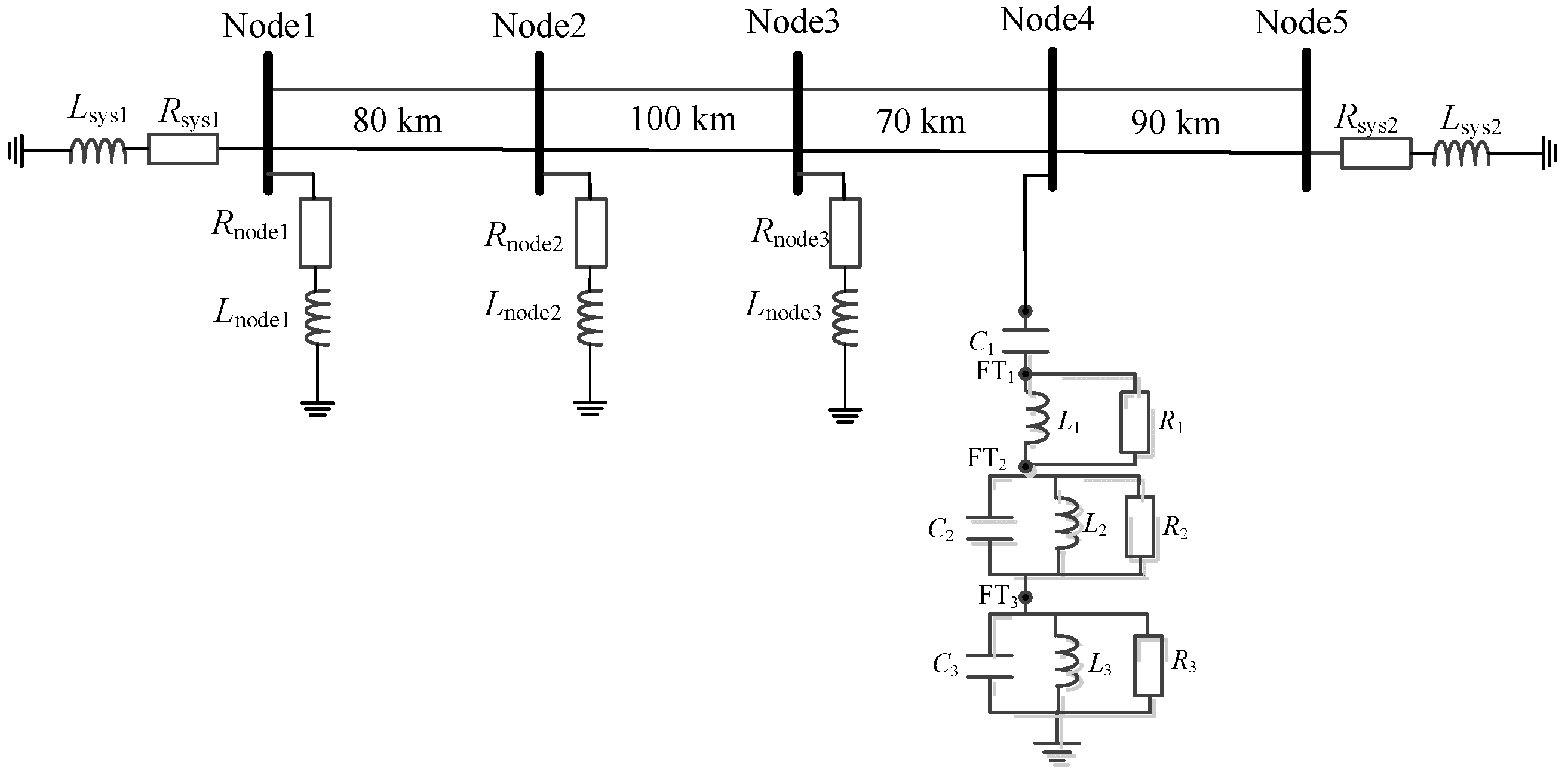
3. Structure and Parameters of the Benchmark System
4. Calculation of Resonant Modes and Voltage Mode Shapes for the Benchmark System
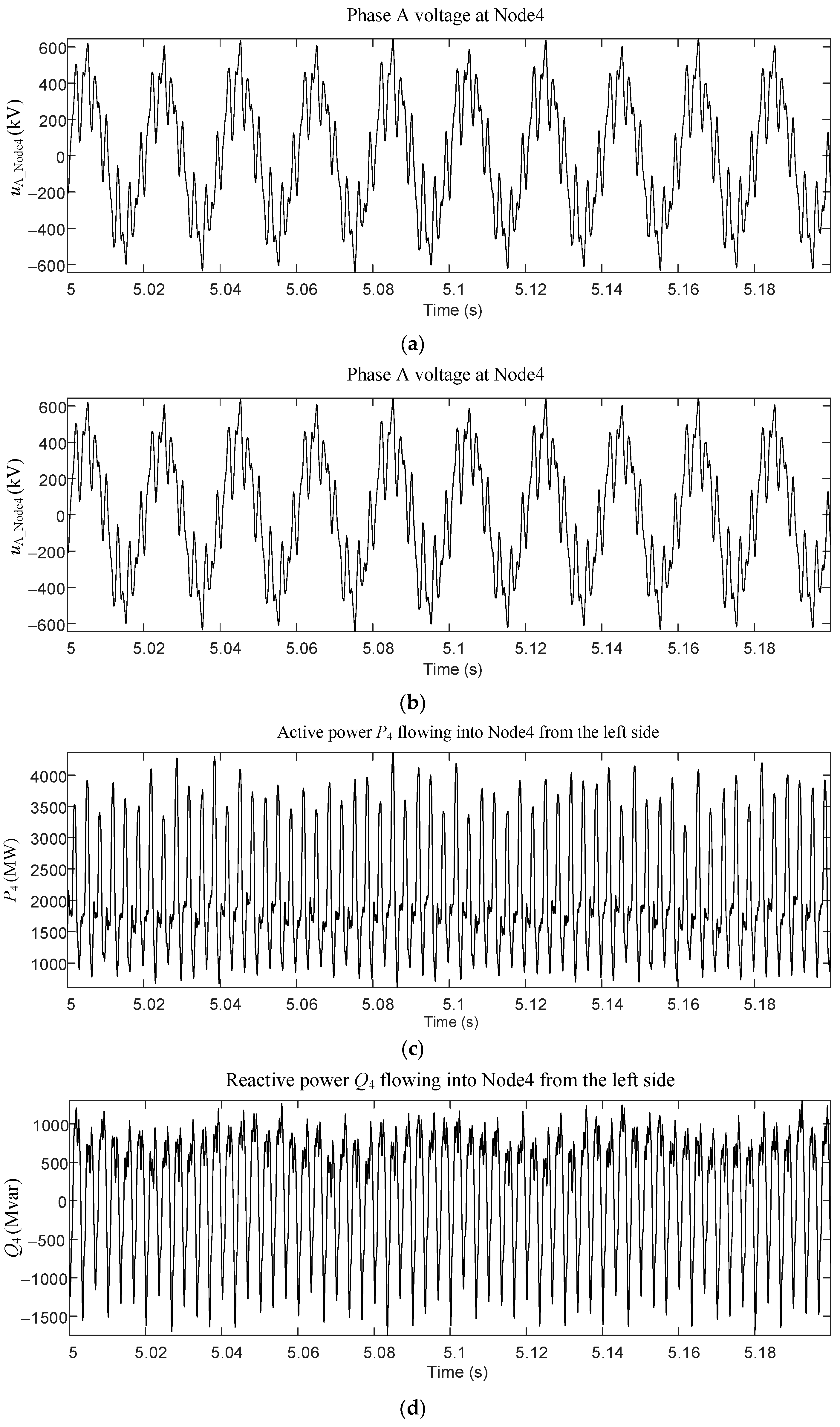
5. Time-Domain Waveform Presentation
6. Harmonic Decomposition Results and Characteristic Analysis of Current Waveforms
7. Harmonic Decomposition Results and Characteristic Analysis of Voltage Waveforms
8. Results of Harmonic Decomposition of Power Waveform and Its Characteristic Analysis
8.1. Basic Characteristics of Oscillatory Power Components in Three-Phase AC Systems
- (1)
- If the power oscillation frequency lies within the subsynchronous frequency range, i.e., fpower < f0, then the voltage and current in the grid must be positive-sequence quantities. Moreover, their oscillation frequency can be expressed by the following formula:
- (2)
- If the power oscillation frequency exceeds the fundamental frequency, i.e., fpower > f0, then determining the oscillation frequency of the voltage and current in the network is relatively straightforward, as shown in the following formula:
8.2. Harmonic Decomposition Results of Power Waveforms in the Benchmark System and Their Characteristic Analysis
9. Conclusions
- (1)
- Due to the modulation effect of power electronic devices on background harmonics, the frequency spectrum distribution of harmonic sources in the power grid is very extensive. It is reasonable to describe power electronic devices using a wideband voltage source converter model or a wideband current source converter model.
- (2)
- The electromagnetic transient simulation results in this paper demonstrate the applicability of analyzing the harmonic amplification effect based on the positive sequence grid model.
- (3)
- The external manifestations of harmonic amplification are wideband power oscillations, overvoltages, and waveform distortion. The four key elements determining the harmonic amplification effect are the resonance frequency, damping ratio, node voltage mode shape, and resonance peak voltage. Among these, the first three elements are determined by the grid topology and grid component parameters, have little correlation with the power generation output and load level of the grid, and are relatively fixed characteristics. The resonance peak voltage is closely related to the distribution and magnitude of harmonic sources and therefore is closely related to the output level and distribution of renewable energy sources as well as the load level and distribution of the grid, exhibiting randomness and volatility.
- (4)
- The first three elements corresponding to the harmonic amplification effect—the resonance frequency, damping ratio, and node voltage mode shape—can be solved using the s-domain nodal admittance matrix method based on the positive sequence network model of the power system.
- (5)
- The frequency corresponding to the oscillatory power component is not equal to the resonance frequency of the grid; the difference between them is the fundamental frequency, and the specific relationship depends on the phase sequence of the harmonic source.
- (6)
- It is infeasible to determine the node voltage mode shape through the numerical distribution of the oscillatory power components, and it is also infeasible to determine the location of harmonic sources through the numerical distribution of the oscillatory power components.
Funding
Data Availability Statement
Conflicts of Interest
References
- Liu, Z.; Li, D.; Wang, W.; Wang, J.; Gong, D. A Review of the Research on the Wide-Band Oscillation Analysis and Suppression of Renewable Energy Grid-Connected Systems. Energies 2024, 17, 1809. [Google Scholar] [CrossRef] [Scilit]
- Chen, L.; Xu, S.; Sun, H. Survey on wide-frequency oscillation for power systems with high penetration of power electronics. Proc. CSEE 2021, 41, 2297–2309. (In Chinese) [Google Scholar] [CrossRef]
- An, S.; Qiu, W.; Pu, Q.; Chen, S.; Zheng, Y.; Duan, J. Power system wideband oscillation estimation, localization, and mitigation. IET Gener. Transm. Distrib. 2023, 17, 2655–2666. [Google Scholar] [CrossRef] [Scilit]
- Ren, C.; Ren, J.; Wang, Z.; Cheng, L.; Xu, H. Construction of cloud-edge-end collaborative prevention and control system for wide-band oscillations in high proportion renewable energy power grid. New Type Power Syst. 2025, 3, 466–473. (In Chinese) [Google Scholar] [CrossRef]
- Sun, J. Impedance-Based Stability Criterion for Grid-Connected Inverters. IEEE Trans. Power Electron. 2011, 26, 3075–3078. [Google Scholar] [CrossRef] [Scilit]
- Liao, Y.; Wang, X. Impedance-Based Stability Analysis for Interconnected Converter Systems With Open-Loop RHP Poles. IEEE Trans. Power Electron. 2020, 35, 4388–4397. [Google Scholar] [CrossRef] [Scilit]
- Tan, Y.; Sun, Y.; Lin, J.; Yuan, L.; Su, M. Revisit Impedance-Based Stability Analysis of VSC-HVDC System. IEEE Trans. Power Syst. 2024, 39, 1728–1738. [Google Scholar] [CrossRef] [Scilit]
- Yang, D.; Sun, Y. SISO Impedance-Based Stability Analysis for System-Level Small-Signal Stability Assessment of Large-Scale Power Electronics-Dominated Power Systems. IEEE Trans. Sustain. Energy 2022, 13, 537–550. [Google Scholar] [CrossRef] [Scilit]
- Zhang, C.; Molinas, M.; Rygg, A.; Cai, X. Impedance-Based Analysis of Interconnected Power Electronics Systems: Impedance Network Modeling and Comparative Studies of Stability Criteria. IEEE J. Emerg. Sel. Top. Power Electron. 2020, 8, 2520–2533. [Google Scholar] [CrossRef] [Scilit]
- Xu, Z.; Xiao, H.; Zhang, Z. Flexible Power Transmission Systems Based on Cascaded Submodule Converters; Springer Nature: Singapore, 2026; Available online: https://link.springer.com/book/10.1007/978-981-95-0861-7 (accessed on 6 January 2026).
- Xu, Z. Analysis of Wideband Oscillation Mechanism and Suppression Technology Based on C-Type Damping Filter. Energies 2026, 19, 943. [Google Scholar] [CrossRef] [Scilit]
- Waniek, C.; Wohlfahrt, T.; Myrzik, J.M.A.; Meyer, J.; Klatt, M.; Schegner, P. Supraharmonics: Root causes and interactions between multiple devices and the low voltage grid. In Proceedings of the 2017 IEEE PES Innovative Smart Grid Technologies Conference Europe (ISGT-Europe), Turin, Italy, 26–29 September 2017; pp. 1–6. [Google Scholar] [CrossRef] [Scilit]
- Rönnberg, S.K.; Castro, A.G.-d.; Bollen, M.H.J.; Moreno-Munoz, A.; Romero-Cadaval, E. Supraharmonics from power electronics converters. In Proceedings of the 2015 9th International Conference on Compatibility and Power Electronics (CPE), Costa da Caparica, Portugal, 24–26 June 2015; pp. 539–544. [Google Scholar] [CrossRef] [Scilit]
- De Rosa, F.; Langella, R.; Sollazzo, A.; Testa, A. On the interharmonic components generated by adjustable speed drives. IEEE Trans. Power Deliv. 2005, 20, 2535–2543. [Google Scholar] [CrossRef] [Scilit]
- Constante, J.R.; Guerron, G.E.; Garcia, E.M. Modeling, Limits and Baseline of Voltage Interharmonics Generation in Andean Wind Farms. IEEE Lat. Am. Trans. 2016, 14, 1271–1278. [Google Scholar] [CrossRef]
- Sangwongwanich, A.; Yang, Y.; Sera, D.; Soltani, H.; Blaabjerg, F. Analysis and Modeling of Interharmonics From Grid-Connected Photovoltaic Systems. IEEE Trans. Power Electron. 2018, 33, 8353–8364. [Google Scholar] [CrossRef] [Scilit]
- Sangwongwanich, A.; Blaabjerg, F. Mitigation of Interharmonics in PV Systems With Maximum Power Point Tracking Modification. IEEE Trans. Power Electron. 2019, 34, 8279–8282. [Google Scholar] [CrossRef] [Scilit]
- Kimbark, E.W. Direct Current Transmission; Wiley-Interscience: New York, NY, USA, 1971; ISBN 0471475807. [Google Scholar]
- Anderson, P.M. Analysis of Faulted Power Systems; Wiley-IEEE Press: New York, NY, USA, 2003; ISBN 0780311450. [Google Scholar]
- Balabanian, N.; Bickart, T.A.; Seshu, S. Electrical Network Theory; John Wiley & Sons: New York, NY, USA, 1969; ISBN 471045764. [Google Scholar]
- Katsuhiko, O. Modern Control Engineering, 5th ed.; Prentice Hall: New York, NY, USA, 2010; ISBN 9780136156734. [Google Scholar]
- Xu, Z. Resonance stability analysis method based on s-domain node admittance matrix. Electr. Power Autom. Equip. 2023, 43, 1–8. (In Chinese) [Google Scholar] [CrossRef]
- Arrillaga, J.; Bradley, D.A.; Bodger, D.S. Power System Harmonics; John Wiley & Sons: Hoboken, NJ, USA, 1985; Available online: https://onlinelibrary.wiley.com/doi/book/10.1002/0470871229 (accessed on 6 January 2026).



| Electrical Parameters per Unit Length | R (Ω/km) | L (mH/km) | C (μF/km) |
|---|---|---|---|
| Positive sequence/Negative sequence | 0.0196 | 0.8780 | 0.01313 |
| Zero sequence | 0.1522 | 2.2840 | 0.009879 |
| Item | Phase A Equivalent Resistance Rsys (Ω) | Phase A Equivalent Inductance Lsys (mH) | Phase A Equivalent Electromotive Force Magnitude Esys (kV) | Phase A Equivalent Electromotive Force Phase Angle δsys (°) |
|---|---|---|---|---|
| Sending-end AC system 1 | 1.25 | 39.8 | 408.2483 × 1.01952 | 11.4492 |
| Receiving-end AC system 2 | 0.625 | 19.9 | 408.2483 × 1.07003 | −0.20328 |
| Item | Node1 | Node2 | Node3 |
|---|---|---|---|
| Phase A equivalent resistance Rnode (Ω) | 7.5 | 3.75 | 7.5 |
| Phase A equivalent inductance Lnode (mH) | 238.7 | 119.4 | 238.7 |
| Phase A fundamental-frequency equivalent electromotive force frequency f0 (Hz) | 50 | 50 | 50 |
| Phase A fundamental-frequency equivalent electromotive force magnitude Enode (kV) | 408.2483 × 1.01624 | 408.2483 × 1.01809 | 408.2483 × 1.1363 |
| Phase A fundamental-frequency equivalent electromotive force phase angle δnode (°) | 19.6573 | 18.1683 | 11.8038 |
| Phase A fundamental-frequency equivalent electromotive force phase sequence | Positive sequence | Positive sequence | Positive sequence |
| Phase A harmonic electromotive force frequency fh_node (Hz) | 30 | 75 | 160 |
| Phase A harmonic electromotive force magnitude Eh_node (kV) | 50 | 50 | 50 |
| Phase A harmonic electromotive force phase angle δh_node (°) | 0 | 0 | 0 |
| Phase A harmonic electromotive force phase sequence | Positive sequence | Negative sequence | Positive sequence |
| Three-Phase Converter Transformer | Rated Capacity (MVA) | Short-Circuit Impedance uk (%) | Grid-Side Rated Voltage Vgn (kV) | Valve-Side Rated Voltage Vvn/(kV) | Grid-Side Tap Position (%) |
|---|---|---|---|---|---|
| 2400 | 18 | 500 | 340 | 98 | |
| Rectifier | Structure | Operating condition | |||
| 6-pulse LCC | DC voltage 400 kV, DC current 5 kA, firing angle 14.2° | ||||
| Equivalent DC system | Rated voltage (kV) | Rated current (kA) | Line resistance Rdc (Ω) | Line inductance Ldc (mH) | Inverter-side equivalent EMF Edc (kV) |
| 400 | 5 | 5.4 | 3000 | 373 | |
| Component | Parameter | Component | Parameter | Component | Parameter |
| R1 (Ω) | 1500 | R2 (Ω) | 400 | R3 (Ω) | 106 |
| L1 (mH) | 8.047 | L2 (mH) | 126.556 | L3 (mH) | 1.608 |
| C1 (μF) | 1.57929 | C2 (μF) | 7.29461 | C3 (μF) | 7.76831 |
| Resonance Mode Number | #1 | #2 | #3 | |
|---|---|---|---|---|
| Resonance frequency (Hz) | 147.6685 | 350.4990 | 632.3371 | |
| Damping ratio | 0.1470 | 0.0100 | 0.0049 | |
| node voltage mode shapes | Node1 | 0.0115 | 0.4000 | −0.7617 |
| Node2 | 0.0228 | 0.7182 | −1.0000 | |
| Node3 | 0.0431 | 1.0000 | −0.1651 | |
| Node4 | 0.0604 | 0.9999 | 0.6853 | |
| Node5 | 0.0207 | 0.3815 | 0.3642 | |
| FT1 | −1.0000 | 0.1693 | −0.0127 | |
| FT2 | −0.9882 | 0.2206 | 0.1274 | |
| FT3 | −0.0024 | −0.0109 | −0.0349 | |
| Row Number | Harmonic Frequency (Hz) | LCC Harmonic Current Source irec (A) | Harmonic Current Amplitude (A) | ||||
|---|---|---|---|---|---|---|---|
| Node1 | Node2 | Node3 | Node4 | Node5 | |||
| 1 | 30 (source) | 14.60 | 685 | 298.44 | 158.27 | 116.87 | 109.60 |
| 2 | 50 (fund.) | 3752.96 | 197.97 | 975.97 | 2571.21 | 3392.74 | 1087.02 |
| 3 | 60 | 11.32 | 1.82 | 2.09 | 3.24 | 4.36 | 7.20 |
| 4 | 70 | 15.54 | 2.53 | 2.89 | 4.44 | 5.94 | 9.92 |
| 5 | 75 (source) | 40.73 | 356.92 | 406.39 | 254.30 | 186.12 | 208.06 |
| 6 | 125 | 26.60 | 5.07 | 5.52 | 7.94 | 10.12 | 18.88 |
| 7 | 140 | 9.02 | 1.83 | 1.95 | 2.74 | 3.42 | 6.67 |
| 8 | 160 (source) | 9.93 | 64.61 | 67.19 | 90.25 | 93.59 | 119.16 |
| 9 | 175 | 44.53 | 10.30 | 10.45 | 13.53 | 15.82 | 35.43 |
| 10 | 225 | 18.50 | 5.93 | 5.45 | 5.92 | 5.87 | 18.28 |
| 11 | 250 (5th) | 385.38 | 157.12 | 135.46 | 129.05 | 109.52 | 451.82 |
| 12 | 270 | 16.25 | 8.55 | 6.95 | 5.75 | 3.93 | 23.08 |
| 13 | 330 | 3.90 | 8.59 | 5.55 | 1.75 | 2.02 | 18.23 |
| 14 | 350 (7th) | 52.39 | 698.22 | 407.78 | 32.15 | 313.31 | 1336.80 |
| 15 | 360 | 8.56 | 41.18 | 22.74 | 1.73 | 22.68 | 74.53 |
| 16 | 370 | 16.35 | 41.55 | 21.58 | 4.94 | 26.96 | 70.78 |
| 17 | 375 | 43.69 | 90.58 | 45.54 | 14.36 | 63.11 | 149.47 |
| 18 | 475 | 37.74 | 24.24 | 3.36 | 21.77 | 33.38 | 13.65 |
| 19 | 550 (11th) | 217.25 | 166.05 | 28.04 | 219.53 | 243.60 | 36.41 |
| 20 | 570 | 10.73 | 10.02 | 2.55 | 14.10 | 14.27 | 4.13 |
| 21 | 630 | 1.71 | 20.62 | 10.66 | 32.62 | 23.50 | 19.33 |
| 22 | 650 (13th) | 240.63 | 608.99 | 369.17 | 980.72 | 607.03 | 663.72 |
| 23 | 660 | 5.59 | 8.95 | 5.83 | 14.48 | 8.21 | 10.39 |
| 24 | 670 | 7.82 | 9.04 | 6.30 | 14.68 | 7.53 | 11.12 |
| 25 | 675 | 22.18 | 22.69 | 16.29 | 36.83 | 17.90 | 28.60 |
| 26 | 775 | 13.74 | 3.92 | 4.57 | 5.58 | 1.01 | 6.61 |
| 27 | 850 (17th) | 170.75 | 35.20 | 52.50 | 36.03 | 38.36 | 58.33 |
| 28 | 950 (19th) | 107.71 | 24.56 | 46.54 | 5.28 | 47.06 | 23.10 |
| Frequency (Hz) | Item | irec | Node1 | Node2 | Node3 | Node4 | Node5 |
|---|---|---|---|---|---|---|---|
| 350.4990 | node voltage mode shape | - | 0.4000 | 0.7182 | 1.0000 | 0.9999 | 0.3815 |
| 350 | Harmonic current (A) | 52.39 | 698.22 | 407.78 | 32.15 | 313.31 | 1336.80 |
| 350 | Harmonic current amplification factor | - | 13.3 | 7.8 | 0.61 | 5.9 | 25.5 |
| 632.3371 | node voltage mode shape | - | −0.7617 | −1.0000 | −0.1651 | 0.6853 | 0.3642 |
| 630 | Harmonic current (A) | 1.71 | 20.62 | 10.66 | 32.62 | 23.50 | 19.33 |
| 630 | Harmonic current amplification factor | - | 12.1 | 6.2 | 19.1 | 13.7 | 11.2 |
| Frequency (Hz) | Harmonic Voltage Amplitude (kV) | ||||
|---|---|---|---|---|---|
| Node1 | Node2 | Node3 | Node4 | Node5 | |
| 30 (Source at Node1) | 5.21 | 3.23 | 1.91 | 1.24 | 0.42 |
| 50 (Fundamental) | 417.11 | 417.85 | 419.35 | 414.83 | 430.13 |
| 75 (Source at Node2) | 6.71 | 13.53 | 8.42 | 5.80 | 1.96 |
| 160 (Source at Node3) | 2.59 | 5.12 | 9.58 | 6.93 | 2.38 |
| 250 (5th) | 9.82 | 18.75 | 31.62 | 39.50 | 14.12 |
| 350 (7th) | 61.11 | 109.77 | 153.09 | 153.39 | 58.5 |
| 360 | 3.71 | 6.61 | 9.0 | 8.73 | 3.35 |
| 370 | 3.84 | 6.80 | 9.02 | 8.45 | 3.27 |
| 375 | 8.49 | 14.97 | 19.59 | 18.01 | 7.01 |
| 550 (11th) | 22.83 | 33.70 | 19.45 | 5.33 | 2.50 |
| 630 | 3.25 | 4.28 | 0.76 | 2.88 | 1.52 |
| 650 (13th) | 98.98 | 126.33 | 9.26 | 98.50 | 53.94 |
| 850 (17th) | 7.48 | 6.17 | 6.86 | 7.15 | 6.20 |
| 950 (19th) | 5.84 | 3.41 | 6.35 | 2.20 | 2.74 |
| Frequency (Hz) | Item | Node1 | Node2 | Node3 | Node4 | Node5 |
|---|---|---|---|---|---|---|
| 350.4990 | node voltage mode shape | 0.4000 | 0.7182 | 1.0000 | 0.9999 | 0.3815 |
| 350 | Harmonic voltage (kV) | 61.11 | 109.77 | 153.09 | 153.39 | 58.5 |
| 350 | Resonant peak voltage (kV) | 152.8 | 152.8 | 153.1 | 153.4 | 153.3 |
| 375 | Harmonic voltage (kV) | 8.49 | 14.97 | 19.59 | 18.01 | 7.01 |
| 375 | Resonant peak voltage (kV) | 21.2 | 20.8 | 19.59 | 18.01 | 18.4 |
| 632.3371 | node voltage mode shape | −0.7617 | −1.0000 | −0.1651 | 0.6853 | 0.3642 |
| 630 | Harmonic voltage (kV) | 3.25 | 4.28 | 0.76 | 2.88 | 1.52 |
| 630 | Resonant peak voltage (kV) | 4.27 | 4.28 | 4.6 | 4.20 | 4.17 |
| 650 | Harmonic voltage (kV) | 98.98 | 126.33 | 9.26 | 98.50 | 53.94 |
| 650 | Resonant peak voltage (kV) | 129.9 | 126.3 | 56.1 | 143.7 | 148 |
| Row Number | fpower (Hz) | Active Power Amplitude (MW) | ||||
|---|---|---|---|---|---|---|
| P1 | P2 | P3 | P4 | P5 | ||
| 1 | 0 | 107.52 | 608.60 | 1605.98 | 2099.88 | 65.39 |
| 2 | 20 | 426.97 | 188.74 | 102.95 | 75.54 | 70.04 |
| 3 | 110 | 38.99 | 40.81 | 60.13 | 72.22 | 76.36 |
| 4 | 125 | 228.62 | 256.91 | 165.33 | 127.59 | 144.90 |
| 5 | 280 | 12.21 | 12.17 | 10.10 | 6.64 | 12.87 |
| 6 | 300 | 465.62 | 370.73 | 899.69 | 1083.62 | 1088.45 |
| 7 | 320 | 61.47 | 61.93 | 70.36 | 75.54 | 63.92 |
| 8 | 410 | 28.27 | 18.74 | 34.62 | 54.57 | 45.81 |
| 9 | 425 | 84.02 | 69.28 | 149.17 | 154.11 | 93.40 |
| 10 | 475 | 17.63 | 23.13 | 11.19 | 5.45 | 4.32 |
| 11 | 580 | 28.13 | 11.27 | 21.60 | 22.98 | 16.84 |
| 12 | 600 | 427.45 | 322.38 | 678.59 | 679.03 | 561.50 |
| 13 | 620 | 94.34 | 59.49 | 13.95 | 31.72 | 9.85 |
| 14 | 710 | 12.10 | 6.51 | 9.21 | 17.08 | 9.02 |
| 15 | 725 | 47.95 | 61.99 | 18.63 | 58.06 | 27.13 |
| 16 | 900 | 47.49 | 48.29 | 91.45 | 97.50 | 34.47 |
| Freq. (Hz) | Item | Node1 P1 | Node2 P2 | Node3 P3 | Node4 P4 | Node5 P5 |
|---|---|---|---|---|---|---|
| 350.4990 | Node voltage mode shape | 0.4000 | 0.7182 | 1.0000 | 0.9999 | 0.3815 |
| 300 | Oscillatory power component (MW) | 465.62 | 370.73 | 899.69 | 1083.62 | 1088.45 |
| 632.3371 | Node voltage mode shape | −0.7617 | −1.0000 | −0.1651 | 0.6853 | 0.3642 |
| 600 | Oscillatory power component (MW) | 427.45 | 322.38 | 678.59 | 679.03 | 561.50 |
Disclaimer/Publisher’s Note: The statements, opinions and data contained in all publications are solely those of the individual author(s) and contributor(s) and not of MDPI and/or the editor(s). MDPI and/or the editor(s) disclaim responsibility for any injury to people or property resulting from any ideas, methods, instructions or products referred to in the content. |
© 2026 by the author. Licensee MDPI, Basel, Switzerland. This article is an open access article distributed under the terms and conditions of the Creative Commons Attribution (CC BY) license.
Share and Cite
Xu, Z. A Benchmark System for Verifying the Harmonic Amplification Mechanism of Wideband Oscillations. Energies 2026, 19, 2569. https://doi.org/10.3390/en19112569
Xu Z. A Benchmark System for Verifying the Harmonic Amplification Mechanism of Wideband Oscillations. Energies. 2026; 19(11):2569. https://doi.org/10.3390/en19112569
Chicago/Turabian StyleXu, Zheng. 2026. "A Benchmark System for Verifying the Harmonic Amplification Mechanism of Wideband Oscillations" Energies 19, no. 11: 2569. https://doi.org/10.3390/en19112569
APA StyleXu, Z. (2026). A Benchmark System for Verifying the Harmonic Amplification Mechanism of Wideband Oscillations. Energies, 19(11), 2569. https://doi.org/10.3390/en19112569