Article

Electromechanical Propagation of Rope Vibration to Grid-Side Low-Frequency Oscillations in Gravity Energy Storage Hoisting Systems


1
University of Chinese Academy of Sciences, Beijing 100049, China
2
Institute of Electrical Engineering, Chinese Academy of Sciences, Beijing 100190, China
3
Key Laboratory of Long-Duration and Large-Scale Energy Storage, Chinese Academy of Sciences, Beijing 100190, China
4
Institute of Electrical Engineering and Advanced Electromagnetic Drive Technology, Qilu Zhongke, Ji’nan 250013, China
5
CHN Energy New Energy Technology Research Institute Co., Ltd., Beijing 102211, China
*
Author to whom correspondence should be addressed.
Energies 2026, 19(11), 2568; https://doi.org/10.3390/en19112568
Submission received: 9 April 2026 / Revised: 1 May 2026 / Accepted: 12 May 2026 / Published: 26 May 2026
(This article belongs to the Special Issue Advancements in Energy Storage Technologies)

Abstract

Gravity energy storage systems (GESS) have emerged as a promising long-duration energy storage technology capable of supporting large-scale renewable integration and enhancing grid resilience. However, the modeling framework for the hoisting electromechanical subsystem in wire-rope-based GESS remains underdeveloped, thereby limiting the accurate characterization of its transient grid-connected behavior, dynamic operating response, and cross-domain coupling effects. Existing studies commonly simplify wire ropes and related transmission components as rigid bodies or low-dimensional mechanical elements, failing to adequately account for their flexibility and the resulting high-dimensional nonlinear dynamics. Although related studies in mine hoisting and elevator systems have addressed mechanical vibration phenomena, they primarily focus on mechanical-side effects, such as shock loading and guide-structure response, whereas the mechanism by which flexible mechanical vibrations propagate through electromechanical coupling and influence electrical dynamic performance remains inadequately understood. To address this gap, this study establishes a distributed-parameter model for the wire-rope hoisting mechanism based on Hamilton’s principle and solves the corresponding vibration governing equations using the Galerkin method to capture nonlinear multi-modal dynamics. An electromechanical coupling model is then developed to elucidate how rope-vibration-induced tension fluctuations propagate through the drive chain, resulting in torque ripple, electrical interharmonics, and low-frequency grid-side oscillations. A Bessel-function-based analytical representation is further introduced to explain the formation of interharmonic clusters and beat-frequency phenomena under converter modulation. An experimental prototype is constructed to validate the proposed modeling framework. The measured vibration spectra, beat-frequency characteristics, and torque ripple align closely with analytical predictions, confirming the model’s capability to capture key propagation paths from rope vibration to electromechanical oscillation and grid-side dynamic response. The results provide a solid theoretical foundation for vibration mitigation, dynamic analysis, and control design of hoisting electromechanical subsystems in gravity energy storage applications.

1. Introduction

With the ongoing global energy transition, the large-scale integration of renewable energy has become a central driver in reshaping the global energy structure. However, the intermittent and variable nature of renewable energy sources poses significant challenges to power-grid stability and electricity-supply security. To address these challenges, the development of long-duration energy storage technologies has become increasingly important. These technologies not only mitigate the variability of renewable energy but also enhance the flexibility and stability of power systems, thereby playing a vital role in facilitating the transition toward a low-carbon economy. Gravity energy storage, as a novel form of large-scale physical energy storage, has gained significant attention from researchers due to its safety, environmental sustainability, and flexible site selection [1,2,3,4]. The system works by lifting heavy objects to a high position to store potential energy, which can then be converted into electrical energy when needed. This process relies on the interaction between the hoisting mechanical subsystem and the electrical drive subsystem. In wire-rope-based vertical GESS, the dynamic characteristics of the lifting mechanism and the control behavior of the electrical drive are closely coupled, and this coupling directly affects the operating response and grid-connected performance of the subsystem.
Research on GESS primarily focuses on system design, control strategy optimization, and efficiency improvement. Different approaches to GESS have been explored, including slope-based systems [5,6,7,8,9] and vertical systems using above-ground towers [10] or underground drilling structures. Various mathematical models have been proposed to characterize GESS operations. Tong et al. developed an energy flow model and control strategies across three system levels: power electronics, single-machine, and hybrid systems [11], and proposed capacity configuration strategies for modular GESS. Haider et al. used a macroscopic approach to model system power and energy, optimizing the stacking of heavy objects based on the potential energy of a single mass block [12]. Emrani et al. combined hoisting and hydraulic mechanisms, analyzing the dynamics of synchronous machines and pumps, including factors such as wire rope tension and piston speed [13]. Kropotin et al. improved GESS efficiency with PU-coated multi-rope systems, modeling rope traction storage efficiency [14]. However, most existing studies treat the hoisting transmission mechanism as a rigid body or a low-dimensional mechanical element. This simplification neglects the flexibility of wire ropes and the high-dimensional nonlinear dynamics of multimodal vibrations. Consequently, the transmission of mechanical disturbances through the electromechanical chain remains insufficiently characterized.
Electromechanical coupling models have been developed in several related fields to describe the mutual interaction between mechanical vibration and electrical control. In electric vehicles, such models have been used in Noise, Vibration, Harshness (NVH) analysis to investigate the coupled responses of motors, gear reducers, and power converters [15,16,17]. In traction systems, torsional vibration arising from drivetrain characteristics and electromagnetic torque excitation has also been recognized as a typical form of electromechanical resonance [18]. These studies provide useful analytical insights, but they are mainly concerned with drivetrain resonance, modal response, or vibration transfer within the drive system itself. They do not sufficiently address the propagation mechanism through which flexible lifting-component vibration is transformed, via motor-converter interaction, into electrical interharmonics and grid-side low-frequency oscillations.
The wire-rope hoisting mechanism in vertical GESS shares structural similarities with high-speed elevators and mine hoisting systems and can be seen as a constrained mechanical system with nonconservative forces. Existing modeling approaches include lumped-parameter models [19,20,21], which are computationally efficient, and distributed-parameter models [22,23,24], which provide higher fidelity in representing flexible vibration behavior and complex nonlinear dynamics [25]. However, studies in elevator and mine hoisting systems mainly focus on mechanical-side issues such as ride comfort, impact loading, structural response, and vibration suppression. Although these studies address vibration phenomena in lifting systems, they do not explain how rope-induced mechanical disturbances propagate through the electromechanical chain and further influence torque pulsation, electrical harmonics, and grid-connected dynamic behavior.
Overall, a critical research gap persists: existing GESS frameworks generally rely on decoupled modeling approaches, simplified lumped-parameter mechanical representations, and idealized electrical sources, which fail to capture the complex frequency shifting and harmonic modulation introduced by dual-PWM (Pulse-Width Modulation) switching. This study bridges this gap by developing a comprehensive multi-physics electromechanical coupling model. By integrating a distributed-parameter rope-vibration model with a coupled PMSM and dual-PWM converter modulation model, this integrated framework reveals the complete propagation pathway from localized mechanical tension fluctuations to grid-side power quality deterioration. Combined with time-frequency analysis and experimental validation, this study provides theoretical support for the dynamic analysis and control design of hoisting electromechanical subsystems in GESS.

2. Mechanical System Model of GESS

Current modeling studies on GESS mainly focus on the grid-connected characteristics and macro-level control strategies of their electrical subsystems under typical start-up, shutdown, and load-variation conditions. However, the mechanical subsystem inherently possesses vibration characteristics that can introduce disturbances to the electrical subsystem, yet these effects are often overlooked. For example, in a hoisting system with a 50-ton payload, the mass of the hoisting rope alone may exceed 20 tons, making its dynamic behavior impossible to neglect. To achieve an accurate mechanical-electrical coupled model of GESS, this chapter first establishes a distributed-parameter model of the hoisting rope based on Hamilton’s principle and derives the governing equation of longitudinal oscillation using spatial coordinate transformation and the Lagrange equation. The Galerkin weighted residual method is then applied to obtain numerical solutions. Finally, the natural frequencies of a deep-shaft gravity energy storage hoisting system are computed and analyzed.

2.1. Distributed-Parameter Model of the Hoisting Rope System

The drum hoist serves as the core electromechanical component of GESS, and its configuration is analogous to that of large-power mine hoisting systems and high-speed elevator traction systems. Due to the complex structure of the hoisting rope, its mass, axial stiffness, and self-weight-induced deformation significantly affect its dynamic behaviour. These factors generate longitudinal vibration during operation, thereby adversely affecting load stability and operational safety.
Conventional rigid-body transmission models, which assume instantaneous torque transfer and infinite mechanical stiffness, mathematically mask these critical low-frequency structural dynamics. For instance, during large-scale energy discharge (payload lowering), the continuous increase in rope length significantly reduces the equivalent stiffness, driving the mechanical natural frequency downward. A rigid-body assumption falsely predicts adequate stability margins by failing to predict the electromechanical resonance that occurs when this drifting ultra-low mechanical frequency overlaps with the electrical control bandwidth. Thus, a distributed-parameter model is indispensable for defining the actual stability boundaries of cross-domain coupling dynamics.
To capture these dynamics, modeling approaches typically fall into two categories: lumped-parameter and distributed-parameter models. Lumped-parameter models, which concentrate the rope mass at discrete points, are computationally efficient but neglect the rope’s inherent flexibility and continuity, often failing to represent essential high-fidelity behaviors [26,27,28,29,30]. In contrast, distributed-parameter models treat the rope as an axially moving string with parameters distributed continuously in time and space. By utilizing partial differential equations, these models provide a more realistic representation of rope elasticity and wave propagation [31,32,33].
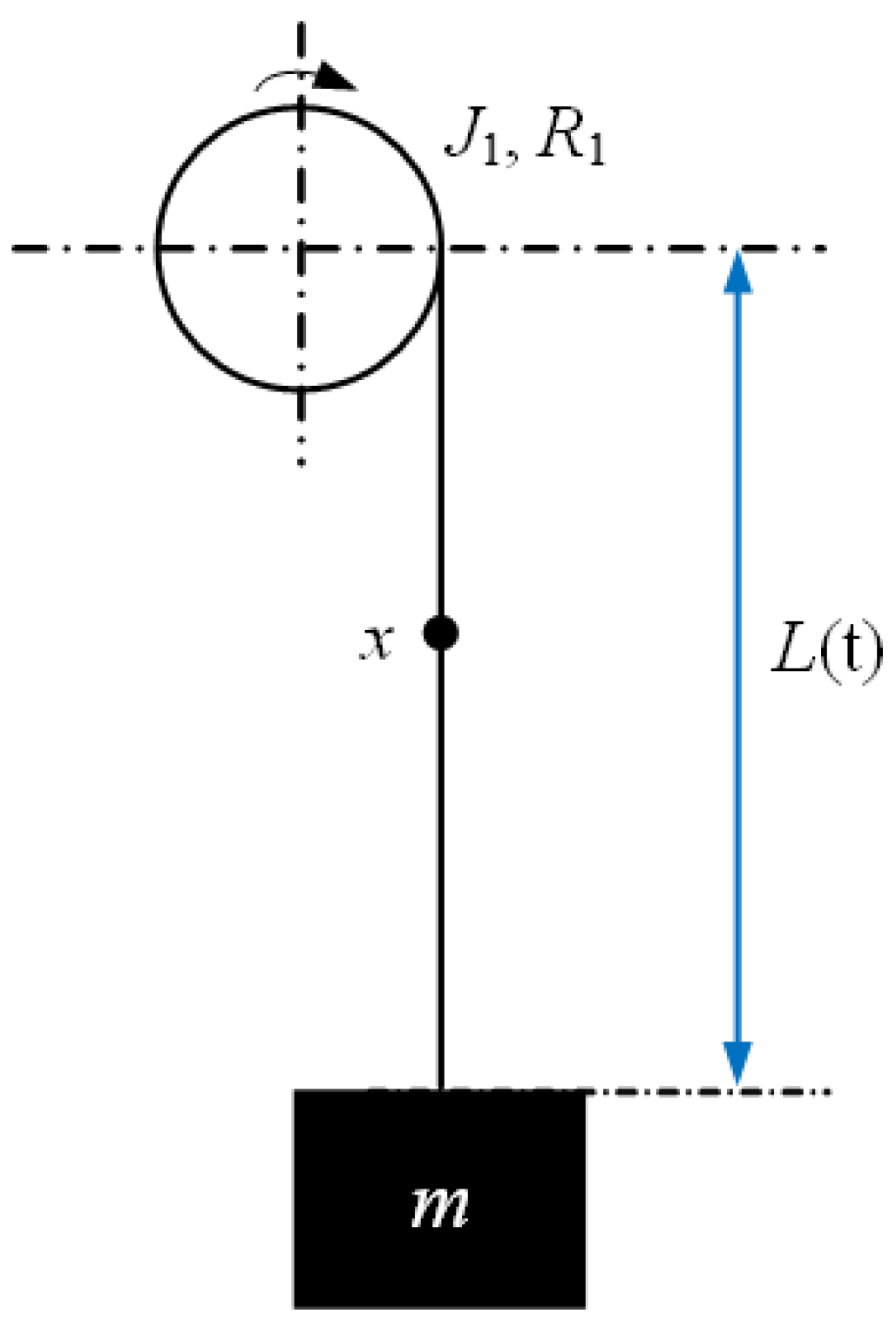
In this study, the mechanical system is modeled using a distributed-parameter approach, where the rope’s elasticity and damping are treated as continuous properties along its length. As such, the kinematic diagram in Figure 1 is primarily utilized to illustrate the geometric relationships, while discrete representations of elastic and damping elements are omitted. To delineate the physical boundaries of the distributed-parameter model, this study isolates the longitudinal vibration propagation induced by electromechanical coupling. It is assumed that the lifting mechanism is equipped with standard anti-sway devices that effectively suppress horizontal and transverse oscillations. Consequently, the dynamic formulation retains only the longitudinal degrees of freedom along the vertical axis, omitting the secondary coupling effects of lateral sway.
The axial displacement of any point x (0 < x < l) along the rope is expressed as
s = x + u ( x , t )
where u denotes the axial displacement at position x and is a function of x and t. The corresponding velocity is
v = x ˙ + d u ( x , t ) d t = l ˙ ( t ) + u x ( x , t ) l ˙ ( t ) + u t ( x , t )
The total kinetic energy of the system is
E k = 1 2 ρ 0 l ( t ) v 2 d x + 1 2 m v 2 | x = l ( t ) + 1 2 J 1 R 1 2 v 2 | x = 0
where ρ is the rope’s linear density; J1 and R1 denote the moment of inertia and radius of the pulley. The first term corresponds to the kinetic energy of all infinitesimal rope elements, the second to the kinetic energy of the payload, and the third to the rotational kinetic energies of the pulley.
The elastic potential energy is
E e = 0 l ( t ) T ( x , t ) + 1 2 E A u x ( x , t ) u x ( x , t ) d x
where E is the Young’s modulus, A is the cross-sectional area, and T denotes the static rope tension given by
T ( x , t ) = m + ρ ( l ( t ) x ) g
The first term in (4) represents the elastic energy stored due to static tension, while the second term corresponds to the energy associated with dynamic strains.
The gravitational potential energy of the system is
E g = 0 l ( t ) ρ g s d x m g s | x = l ( t )
where the first term accounts for the rope’s self-weight and the second for the payload weight.
The virtual work of the damping-induced energy dissipation is written as
W = 0 l ( t ) μ E A u x t ( x , t ) u x ( x , t ) d x
where μ is the damping coefficient and uxt(x,t) is the velocity at position x and time t.
Since the system includes external work from the driving motor and energy dissipation from rope damping, it constitutes a non-conservative system. According to the generalized Hamilton principle,
δ t 1 t 2 ( E k E e E g ) d t + t 1 t 2 δ W d t = 0
where δ denotes the variation in the motion trajectory. The first part corresponds to the variation in the difference between kinetic and potential energies, while the second part represents the virtual work of non-conservative forces.
The boundary conditions of the system are:
(1)
Geometric boundary condition: the rope experiences no vibration at the detachment point from the upper sheave:
u ( 0 , t ) = 0 ; δ u ( 0 , t ) = 0
(2)
Temporal boundary condition: variations vanish at the initial and final instants t1 and t2:
δ u ( x , t 1 ) = δ u ( x , t 2 ) = 0
From the expression of static tension (5),
T l ( t ) , t = m g ; T x ( x , t ) = ρ g
Taking variations in (3) through (7), substituting them into (8), and applying the variational principle, integration by parts, and the Leibniz rule, the governing equation of vibration is obtained as
t 1 t 2 0 l ( t ) ρ v t + l ˙ ( t ) v x g T x E A u x x μ E A u t x x δ u d x d t + t 1 t 2 J 1 R 1 2 + J 2 R 2 2 + J 3 R 3 2 v t + l ˙ ( t ) v x δ u | x = 0 d t t 1 t 2 m 1 v t + l ˙ ( t ) v x m 1 g + T + E A u x δ u | x = 0 d t = 0
Since δu(x,t) is an arbitrary independent variation in space and time except at the endpoints, the coefficient of δu(x,t) must vanish, leading to the longitudinal vibration equation of the hoisting rope under free vibration conditions:
ρ u t t + 2 ρ u x t l ˙ ( t ) + ρ l ¨ ( t ) ( 1 + u x ) + ρ l ˙ 2 ( t ) u x x E A u x x μ E A u t x x = 0
with boundary conditions
x = 0 , J 1 R 1 2 u t t + l ˙ 2 ( t ) u x x + 2 l ˙ ( t ) u x t + l ¨ ( t ) u x + l ¨ ( t ) = 0
x = l ( t ) , m ( u t t + l ˙ 2 ( t ) u x x + 2 u x t l ˙ ( t ) + u x l ¨ ( t ) + l ¨ ( t ) ) = E A u x
Due to the time-varying characteristics of the hoisting rope length l(t), the high-order time derivative in the governing equations describes the absolute acceleration of a mass element, formulated as the material derivative D 2 u D t 2 = 2 u t 2 + 2 v t 2 u x t + v 2 t 2 u x 2 + a t u x , where v(t) and a(t) are the velocity and acceleration. To eliminate the time-varying spatial boundary x 0 , l ( t ) , a dimensionless spatial coordinate ξ = x / l ( t ) is introduced, mapping the system to a fixed domain ξ 0 , 1 . By applying the chain rule, the spatial and temporal partial derivatives are transformed as u x = 1 l ( t ) u ξ and 2 u t 2 = 2 u τ 2 2 v ( t ) ξ l ( t ) 2 u ξ τ + v 2 ( t ) ξ 2 l 2 ( t ) 2 u ξ 2 + 2 v 2 ( t ) ξ l 2 ( t ) a ( t ) ξ l ( t ) u ξ .

2.2. Numerical Solution of the Hoisting System

Equation (13) derived in Section 2.1 represents a typical high-order physical–mathematical model. Because the hoisting rope possesses infinitely many degrees of freedom, analytical solutions are generally intractable. For the rope vibration problem, finite element methods (FEM) offer the flexibility to handle complex boundary conditions, irregular geometries, and nonlinearities, thereby yielding more accurate numerical solutions. Among FEM techniques, the Galerkin weighted-residual method constitutes a fundamental numerical approach: it converts the weak form of the partial differential equation into a discrete algebraic system by projecting the residual onto chosen trial and weight functions.
Assume the approximate solution of the rope vibration equation has the form
u ( x , t ) = 1 l ( t ) i = 1 n q i ( t ) ϕ i ( ξ )
where qi(t) denotes the i-th generalized coordinate (longitudinal) at time t, and ϕi(ξ) denotes the corresponding mode shape. We adopt the following set of mode functions:
ϕ i ( ξ ) = 2 sin ( i 1 2 ) π ξ
This choice simplifies the numerical procedure and avoids solving transcendental characteristic equations. Nevertheless, these trial functions do not exactly satisfy the complex governing equation and boundary conditions of the rope–payload hoisting system. Substituting the assumed approximation u*(x) into the weak form of the governing equation produces a residual field R(x). To address this, a mixed weighted-residual formulation is employed. This method transforms the PDE into an optimization problem by minimizing the residuals. Specifically, because the boundary conditions are not intrinsically met, we explicitly define boundary residuals alongside the domain residual to quantify the deviation between the trial function and the exact solution [34]:
0 1 ϕ j ( ξ ) R ξ d ξ + ϕ j ( 0 ) R 0 + ϕ j ( 1 ) R 1 = 0 ; ( j = 1 , 2 , )
where the weighting functions are chosen as ϕj(ξ), and Rξ, R0, R1 denote the domain residual and the residuals at the upper and lower boundaries, respectively; these residuals quantify the deviation between the trial approximation and the exact solution. By enforcing the weighted integral of these residuals to evaluate to zero, the approximation error is systematically minimized. Convergence is guaranteed in the weak sense as the expansion order n increases. Furthermore, by avoiding dynamic remeshing associated with the time-varying rope length l(t), this global assumed-modes approach achieves computational accuracy comparable to or superior to local discretized FEM.
Applying the Galerkin weighted-residual procedure reduces the original infinite-dimensional partial differential equation to a finite set of ordinary differential equations, which can be written in matrix form as
M q ¨ + C q ˙ + K q = P
where M is the equivalent mass matrix, C the equivalent damping matrix, K the equivalent stiffness matrix, and P the generalized force vector; the generalized coordinate vector is q = [q1, q2, …, qn]T. Detailed expressions for the matrix entries and the discretization procedure are provided in Appendix A.

2.3. Natural Frequency Analysis of the Hoisting Rope System

Whether a gravity energy storage hoisting system experiences resonance depends on the proximity between its natural frequencies and external excitation frequencies. When these frequencies coincide or become sufficiently close, system response amplitudes can be significantly amplified, potentially leading to dynamic instability. In such systems, the hoisting rope mass often reaches approximately half of the lifted payload mass, rendering its inertial effects non-negligible. Moreover, both the effective mass and equivalent stiffness of the rope vary with the working rope length, thereby introducing pronounced parametric time dependence and nonlinear characteristics into the system. Consequently, the natural frequencies exhibit complex temporal variation. Systematic investigation of the natural-frequency characteristics of gravity energy storage hoisting systems is therefore fundamental for subsequent electromechanical stability analysis and controller design.
While viscous damping is present in the governing Equation (13), its influence on the natural frequency calculation is negligible for the current configuration. Quantitatively, based on the parameters in Table 1, the structural damping ratio ζ of the wire rope is approximately 0.0287. According to the relationship ω d = ω n 1 ζ 2 , this damping level introduces a frequency deviation of less than 0.05%. Sensitivity analysis further indicates that while the damping coefficient μ is critical for determining resonance amplitudes, the natural frequency itself exhibits almost negligible sensitivity to damping variations within the physical range typical for steel ropes (ζ < 0.05). Consequently, the natural-frequency calculation herein considers only equivalent mass and equivalent stiffness for analytical clarity. Linearizing Equation (19) yields
M q ¨ + K q = 0
Assume a free-vibration solution of the form:
q ( t ) = φ e j ω t
where φ denotes the mode-shape vector and ω the natural frequency. Substituting (21) into (20) gives:
( K ω 2 M ) φ = 0
For nontrivial solutions to exist, the coefficient matrix must be singular, which leads to the characteristic equation:
det ( K ω 2 M ) = 0
The eigenvalues ω obtained from (23) correspond to the system’s natural frequencies.
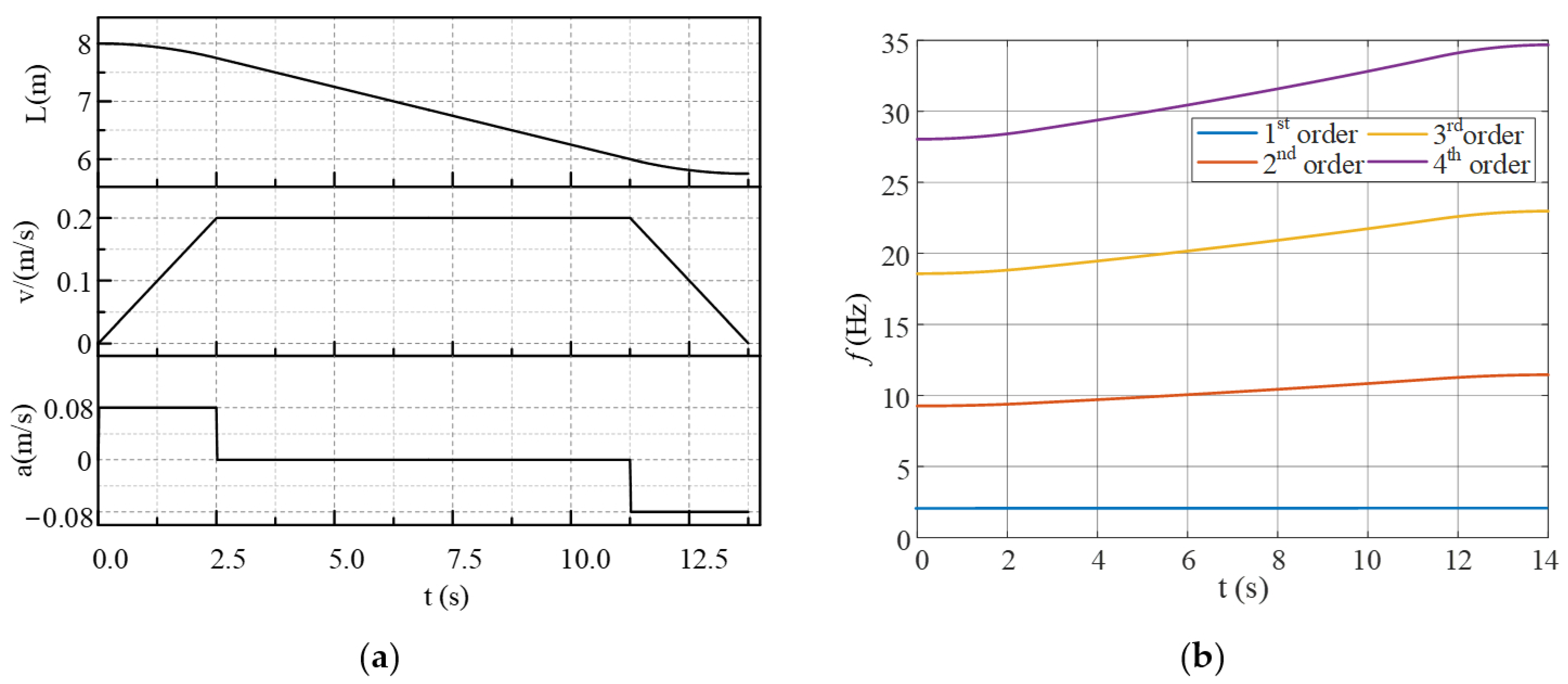
Using the GESS parameters listed in Table 1 and the motion pattern in Figure 2a, the natural-frequency trajectories shown in Figure 2b were computed. As the hoisting proceeds, the rope length shortens, and the equivalent stiffness increases, resulting in monotonic increases in the longitudinal natural frequencies. This frequency variation with rope length exhibits distinct nonlinear behavior.
To address the quantitative margin of error introduced by the trial function approximations, the modal truncation effect is evaluated. Upon solving the eigenvalue problem, modal analysis reveals that the dynamic response of the GESS is strongly dominated by the fundamental modes. Specifically, the longitudinal deformation contribution of the 4th-order mode accounts for less than 1% of the total displacement. Therefore, truncating the expansion at n = 4 limits the theoretical calculation error of the fundamental natural frequency to within approximately 1%. Furthermore, as the rope shortens and the payload mass dominates, the physical mode shape transitions towards a linear profile, which can be efficiently approximated by the sinusoidal basis functions. Consequently, the margin of error for the computed low-frequency trajectories remains strictly bounded below 2% throughout the operating cycle.
During the operation of GESS, longitudinal vibration characteristics are influenced not only by structural parameters but also by various external excitations. Resonance may occur when an external excitation frequency approaches a system’s natural frequency, which can severely impair stability and safety. In these systems, the drive motor and its controller act as the primary dynamic sources and can substantially affect longitudinal vibration behavior. Suppose external perturbations induce parametric excitations of different frequencies and amplitudes in the generalized force term of the longitudinal vibration equation, yielding harmonic responses that can be modeled as:
F harmonic = M [ i = 1 n A m sin ( 2 π f i t ) ] , i = 1 , 2 , 3 , , n
where Am denotes the amplitude of the parametric excitation corresponding to frequency fi (units: Hz).
The generalized force vector of the longitudinal-vibration control equation under external excitation can be expressed as:
P = M [ a + i = 1 n A m sin ( 2 π f i t ) ] , i = 1 , 2 , 3 , , n

3. Transmission Characteristics of the GESS Under Mechanical Load Pulsation

3.1. PMSM Model Considering Torque Ripple

Unlike mine hoisting systems or high-speed elevators, which operate under a unidirectional power-supply mode, GESS exhibit inherent bidirectional energy-exchange characteristics. Conventional vibration studies of hoisting equipment are largely conducted from the perspective of grid-connected users, and their scope usually terminates at the mechanical vibration analysis of the hoisting mechanism itself. In contrast, in GESS, the electromechanical coupling throughout the transmission chain converts mechanical vibrations into torque pulsation components acting on the motor, thereby affecting the grid-side power quality and oscillatory characteristics.
It is important to emphasize that the “vibrational angular velocity” appearing in the model is a mathematical abstraction describing the rate of change in a periodic variable. Although it shares the same physical dimension as rotational angular velocity, it does not correspond to any physical rotational motion. Consequently, the gearbox transfer function exhibits a distinctive frequency-domain property: it modifies only the amplitude of torque fluctuations while preserving their fundamental frequency.
In electrical machines, load fluctuations inevitably distort the air-gap magnetic field through torque coupling, thereby introducing harmonic components into the stator current. These harmonics are subsequently modulated by the four-quadrant converter before being injected into the grid [29]. This study departs from the conventional practice of separately analyzing energy flow during charging and discharging phases; instead, the entire dynamic process is formulated as a bidirectional power-exchange interaction between the GESS and the power grid, where the sign of power directly reflects the phase relationship between system current and grid voltage.
The implemented four-quadrant converter topology naturally facilitates energy recovery during the payload lowering phase. Compared to conventional lifting mechanisms that rely on unidirectional converters supplemented by independent feedback loops for descents, this configuration maintains control effectiveness while simplifying the physical architecture. It provides a generalized basis for analyzing multi-frequency coupling modulation without introducing the additional analytical complexity associated with isolated energy-recovery circuits.
The mechanical load torque applied to the machine is defined as:
For the motor, its mechanical load torque is:
T m = T l o a d + T l sin ( ω l t )
where Tm consists of a fixed value Tload and load torque pulsation. Tl denotes the amplitude of the load torque ripple, and ωl = 2πfl is the angular velocity of the load torque ripple.
Thus, the mechanical motion equation of the motor incorporating load torque ripple is obtained as:
T e m T m = J d ω m d t + B ω m
To simplify calculations, the frictional damping torque m is assumed to be a fixed value and equivalently incorporated into Tload. The fluctuation of the mechanical load will directly affect the motor speed, yielding the rotational angular velocity of the motor rotor as:
ω m = 1 J t 0 t [ T e m T l o a d ] d τ 1 J t 0 t T l sin ( ω l t ) d τ = T l J ω l cos ( ω l t ) + ω m 0
From (28), it can be observed that the motor rotor speed consists of two components: a constant value ωm0 and a periodic oscillation with an angular frequency of ωl. This indicates the presence of a characteristic frequency corresponding to the load fluctuation in the motor rotor speed.
The motor rotor angular displacement is:
θ m ( t ) = t 0 t [ T l J ω l cos ( ω l τ ) + ω m 0 ] d τ = T l J ω l 2 sin ( ω l t ) + ω m 0 t
Similarly, the motor rotor angle consists of two components: a constant value θm0 and a periodic oscillation with an angular frequency of ωl. A characteristic term T l / ( J ω l 2 ) sin ( ω l t ) appears in the rotation angle, indicating that the characteristic frequency of the mechanical load torque fluctuation undergoes phase modulation with this term as its signature.
The angular oscillation component is expressed as:
δ θ ( t ) = T l J ω l 2 sin ( ω l t )
The angular oscillation affects the spatial position of the rotor magnetic field relative to the stator windings, thereby causing fluctuations in the magnetomotive force (MMF). The rotor MMF, generated by the permanent magnets, is given by:
F r ( t ) = F r m cos ( p θ )
where θ’ represents the mechanical rotation angle in the rotor reference frame. To facilitate computational analysis, the permanent magnet MMF in the rotor reference frame is transformed to the stator reference frame. The permanent magnet MMF in the stator reference frame is then expressed as:
F r ( θ , t ) = F r m cos [ p ( θ θ m ) ]
To mathematically justify the analytical approximation from the exact frequency modulation, the electrical angular deviation induced by the torque pulsation is denoted as Δ θ e = p T l J ω l 2 . Utilizing the Jacobi-Anger expansion, the phase-modulated magnetomotive force can be strictly expressed as a series of Bessel functions of the first kind: cos(θe + ∆θesinωlt) = J0θecosθeJ1θe[cos(θe-ωlt) − cos(θe + ωlt)] + ···. Under the operating conditions of the GESS prototype, the substantial equivalent inertia J of the mechanical drivetrain and the specific torque ripple amplitude Tl strictly bound the maximum angular deviation ∆θe. Within this range, the first-order Bessel function coefficient is an order of magnitude larger than the second-order coefficient (J1 ≈ 0.1 >> J2 ≈ 0.01). Consequently, the higher-order harmonic sidebands are mathematically negligible. By retaining only the dominant fundamental and first-order interharmonic components, the approximated expression is yielded as:
F r ( t ) = F r m cos [ p ( θ ω m 0 t ) ] + F r m T l J ω l 2 sin ( ω l t ) sin [ p ( θ ω m 0 t ) ]
The fluctuation components manifest as low-frequency modulations in both time and space, with frequencies of ωl and m0 ± ωl.
In practical PMSM drives, the stator MMF and current spectrum also contain spatial harmonics from the mechanical design (e.g., cogging effects) and time harmonics introduced by inverter nonlinearity. However, given the prototype’s rated electrical frequency fe = 15 Hz, these nonlinearities predominantly generate (6k ± 1)-order harmonics, with the lowest dominant frequencies appearing at 75 Hz and 90 Hz. Conversely, the structural vibration frequencies of the hoisting rope fl are strictly confined to the ultra-low frequency range (≤10 Hz), generating interharmonic sidebands (fe ± fl) bounded between 5~25 Hz. Because a wide frequency margin separates these intrinsic high-frequency parasitic harmonics from the vibration-induced low-frequency interharmonics, their spectra do not overlap. Thus, to maintain analytical clarity for the low-frequency coupling mechanism, these high-frequency factors are mathematically neglected. The fundamental and interharmonic stator MMF is obtained as:
F s ( θ , t ) = F s m cos [ p ( θ ω m t ) ]
When other factors affecting the motor air gap are not considered, the air gap permeance can be regarded as nearly constant. Consequently, the air gap flux density can be expressed as:
B ( θ , t ) = B r m cos [ p ( θ θ m ) ] + B s m cos [ p ( θ ω m t ) ]
The magnetic flux linkage equals the product of the number of turns in the conductive coil and the average magnetic flux through a single-turn coil. Therefore, the stator flux linkage can be obtained by integrating the air-gap flux density based on the winding structure. While the winding structure affects the amplitude of the stator flux linkage, it does not alter its frequency. Consequently, the flux linkage of any stator phase is given by:
u A = R S i A + d ψ A d t u B = R S i B + d ψ B d t u C = R S i C + d ψ C d t
Combining with the stator voltage equation of PMSM:
ψ ( t ) = ψ r m cos [ p ( θ θ m ) ] + ψ s m cos [ p ( θ ω m t ) ]
The stator current of any motor phase can be derived as:
i ( t ) = I 1 sin ( p ω m 0 t ) + I 2 [ sin ( p ω m 0 ± ω l ) t ] + I 3 sin { [ p ( T l J ω l cos ω l t + ω m 0 ) ± ω l ] t ] }
where I1, I2, and I3 denote the steady-state amplitudes of the respective current components. Based on the PMSM stator voltage equation, these amplitudes are determined by the machine parameters (stator resistance Rs, synchronous inductance Ls, permanent magnet flux linkage ψm) and the fundamental terminal voltage vector Us1 synthesized by the inverter control input. Specifically, the fundamental current amplitude is defined as I 1 = U s 1 E 1 / Z p ω m 0 , where E 1 p ω m 0 ψ m J 0 Δ θ e is the fundamental back-EMF, and Z ω = R s 2 + ω L s 2 is the stator impedance. Assuming the current loop controller bandwidth does not fully suppress the vibration-induced disturbances, the inverter output voltage remains predominantly at the fundamental frequency. The interharmonic current amplitudes I2 and I3 are thus primarily driven by the modulated interharmonic back-EMF components, yielding I 2 , I 3 E i h / Z p ω m 0 ± ω l , where the interharmonic back-EMF amplitude is E i h p ω m 0 ψ m J 1 p T l / J ω l 2 .
Since the machine terminal voltage maintains an approximately constant frequency, the single-phase power ripple is primarily governed by current fluctuations. Therefore, mechanical load pulsation introduces harmonic components into the stator current at the pulsation base frequency. Because ωl is typically small, the two characteristic frequencies (m0 ± ωl) and { p [ T l / ( J ω l ) cos ω l t + ω m 0 ] ± ω l } are very close, generating a pronounced beat-frequency effect, which manifests as substantial low-frequency power pulsation.

3.2. Harmonic Model of the Dual-PWM Speed Regulation System Based on Bessel Functions

In addition to the current fluctuations induced by variations in the motor load torque, the motor-side PWM inverter in a dual-PWM AC speed regulation system injects harmonic current components into the DC link, resulting in DC-side voltage ripple. This ripple further couples with the grid-side PWM modulation, causing the injected grid current to contain subharmonic and interharmonic components [35].
The modulation characteristics of dual-PWM drive systems have been extensively investigated in prior studies. Building upon these methods, this work extends the transmission chain involving mechanical oscillation → motor current low-frequency fluctuation → dual-PWM modulation → grid-side low-frequency oscillation dynamics in the context of gravity energy storage hoisting systems.
Considering the motor current ripple, the three-phase stator currents can be expressed as:
i U ( t ) = I 1 cos ( ω I t θ Z ) + k = 1 n I k cos ( ω F k t θ Z k ) i V ( t ) = I 1 cos ( ω I t θ Z 2 π 3 ) + k = 1 n I k cos ( ω F k t θ Z k 2 π 3 ) i W ( t ) = I 1 cos ( ω I t θ Z + 2 π 3 ) + k = 1 n I k cos ( ω F k t θ Z k + 2 π 3 )
By adopting the switching function based on Bessel functions, the equation for the current injected into the DC side by the motor-side PWM inverter is derived as:
i c a = I o + k = 1 n F 1 ( ω I , ω F k ) + k = 1 n F 2 ( ω I , ω F k , ω C )
where ωC = 2πfC represents the carrier angular frequency. F1 and F2 denote the first-order and second-order Bessel functions of the first kind, respectively (see Appendix B). As evident from the analysis, the fluctuation component in ica results from PWM modulation of ωI and ωFk, as well as their combinations with ωC, generating linear combinations of integer multiples of these frequencies. This process introduces significant harmonic and interharmonic components.
Since the grid-side fundamental angular frequency ωS = 2πfS remains constant at 50 Hz, the low-frequency voltage ripples on the DC side caused by grid-side PWM can be neglected. Therefore, the AC component of the DC-side voltage U ˜ d c is primarily induced by the fluctuating current injected into the DC side from the motor-side PWM. To facilitate analytical derivation, it is assumed that i ˜ c a = n = 1 k F 1 ( ω I , ω F k ) . Thus,
u ˜ d c = k = 1 n U k [ sin ( ω F k ω I ) t θ Z k ]
It is evident that the DC bus voltage fluctuations are generated by the motor-side PWM modulation at frequency ωFk.
Furthermore, the DC bus voltage fluctuations give rise to three-phase voltage fluctuations on the grid side, specifically expressed as [36]:
u A N = M 0 + k = 1 n M 1 , k cos [ ( ω F k ω I ± ω S ) t + θ 1 , k ] + k = 1 n M 2 , k D p , q cos { [ ( ω F k ω I ± ( p + q R ) ω S ] t + θ 2 , k }
where R = ωC/ωS represents the carrier ratio of the PWM converter.
After filtering out high-frequency components, the low-frequency interharmonics and subharmonics become the dominant components injected into the grid by the grid-side PWM converter, primarily including:
f i = f S ± ( ω F k ω I ) , ( p + q )   is     even f S ± ( ω F k ω I ) + p = 1 q = 1 ( p + q R ) f S ± ( ω F k ω I ) , ( p + q )   is     odd
As indicated by Equation (43), the electromechanical coupling and subsequent DC-link fluctuations introduce specific low-frequency interharmonic sidebands into the grid-side electrical quantities. Let ωl denote the equivalent low-frequency mechanical perturbation mapped to the grid interface. The grid-side current injected by the converter can thus be analytically synthesized as:
i g t = I m cos ω S t φ 1 + I i h + cos ω S + ω l t φ + + I i h cos ω S ω l t φ
To elucidate why the grid power oscillation frequency strictly mirrors the mechanical vibration frequency ωl, it is necessary to examine the beat-frequency mechanism. Assuming a stiff grid, the grid-side phase voltage remains purely fundamental, expressed as ug(t) = Umcos(ωSt). The instantaneous single-phase active power pg(t) is derived via trigonometric product-to-sum identities:
p g t = u g t i g t = P D C + p 2 ω s t + p b e a t t + p h i g h t
The difference-frequency operation between the 50 Hz voltage and the adjacent current sidebands yields the low-frequency beat envelope:
p b e a t ( t ) = 1 2 U m I i h + cos ω l t φ + + 1 2 U m I i h cos ω l t + φ
Conversely, the sum-frequency operation generates the high-frequency modulation term:
p h i g h ( t ) = 1 2 U m I i h + cos 2 ω s + ω l t φ + + 1 2 U m I i h cos 2 ω s ω l t φ
In a balanced three-phase system, the inherent double-frequency power ripples (2ωs) and the high-frequency modulations (phigh(t)) cancel out mathematically across the three phases. The synchronous summation retains and reinforces the beat component, yielding the total active power:
P 3 ϕ ( t ) = 3 2 U m I m cos φ 1 + 3 2 U m I i h + cos ω l t φ + + I i h cos ω l t + φ
This explicit derivation demonstrates how the dual-PWM system maps mechanical vibration into continuous low-frequency active-power oscillation at the grid interface through the beat-frequency phenomenon.

4. Experimental Setup and Simulation

4.1. Experimental System Construction

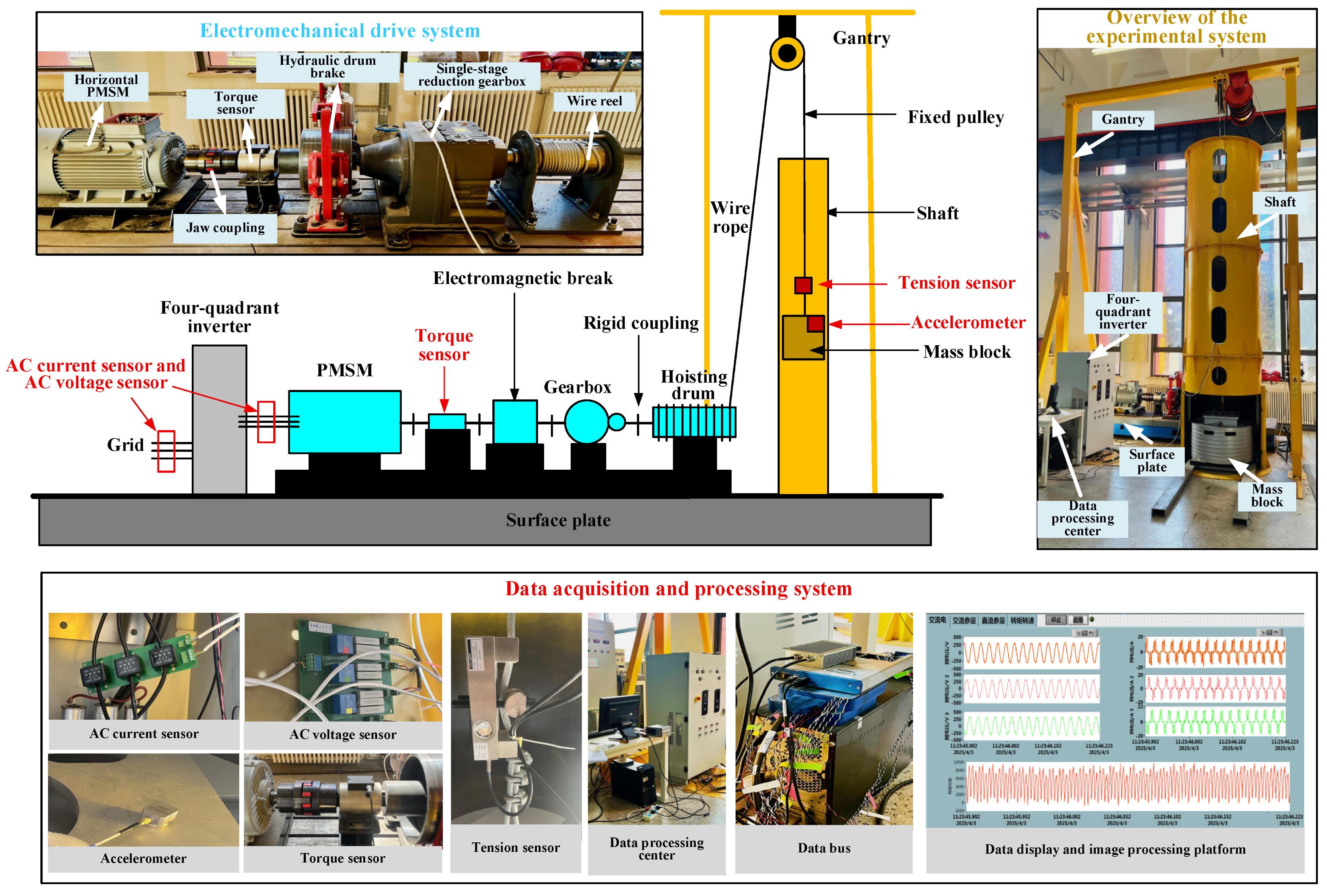
Due to laboratory spatial constraints, a 7.5 kW gravity energy storage prototype platform (Beijing Tianheng Kairui Hoisting Machinery Co., Ltd., Beijing, China) was developed for experimental purposes. The system parameters are detailed in Table 2, with the architectural configuration illustrated in Figure 3. The prototype system interfaces with a standard 380 V distribution network. Relative to the prototype’s capacity, this grid exhibits a Short Circuit Ratio (SCR) >> 10, functioning as an ideal strong grid. This configuration effectively isolates the vibration-induced oscillations from weak-grid dynamic interactions. The dual-PWM drive implements Field Oriented Control (FOC) on the machine side and Voltage Oriented Control (VOC) on the grid side. The electromechanical coupling mechanism identified herein is independent of the grid fundamental frequency; therefore, the proposed analytical framework remains valid for non-50 Hz power systems, with the generated harmonic clusters centered around the corresponding fundamental frequency of the target grid.
The measurement and control system for the prototype is designed to ensure the quantitative reliability of the experimental validation. For electrical parameters, the stator voltages and currents are measured using KV 50 A/P and KT 50 A/P closed-loop Hall-effect sensors (Kehai Electronic Technology Co., Ltd., Beijing, China) with a linearity error of less than 0.2%. For mechanical parameters, the dynamic torque and rotational speed are simultaneously monitored by an NYT302 sensor with a rated capacity of 3000 N·m, paired with a DT45 transmitter, ensuring a transmission error less than ±0.2% F.S. The wire rope tension and the acceleration at the weight end are captured by a COS-5t side-pressure tension sensor (Lijing Microelectronics Equipment Co., Ltd., Tianjin, China) and a QXS-10g triaxial accelerometer (QuanXinSheng, Jingzhou, China) connected to an IEPE high-speed data acquisition unit, respectively. The rotor position is acquired using a resolver.
A LabVIEW 2014-based experimental data acquisition and processing platform was developed for the prototype, enabling the visualization and synchronization of the collected data. To ensure signal fidelity, FFT analysis is configured with multi-rate sampling. The sampling intervals are strictly set to 5 × 10⁻⁵ s (20 kHz) for vibration acceleration, 0.0002 s (5 kHz) for voltages and currents, and 0.000143 s (≈7 kHz) for torque, speed, and tension. A Hanning window is applied to mitigate spectral leakage. A 5 s time window is utilized to yield a fine frequency resolution of 0.2 Hz. The final spectra are generated by averaging 5 consecutive segments with a 50% overlap, thereby reducing noise variance and enhancing the visibility of interharmonic components.

4.2. Simulation Model and Calculation Results

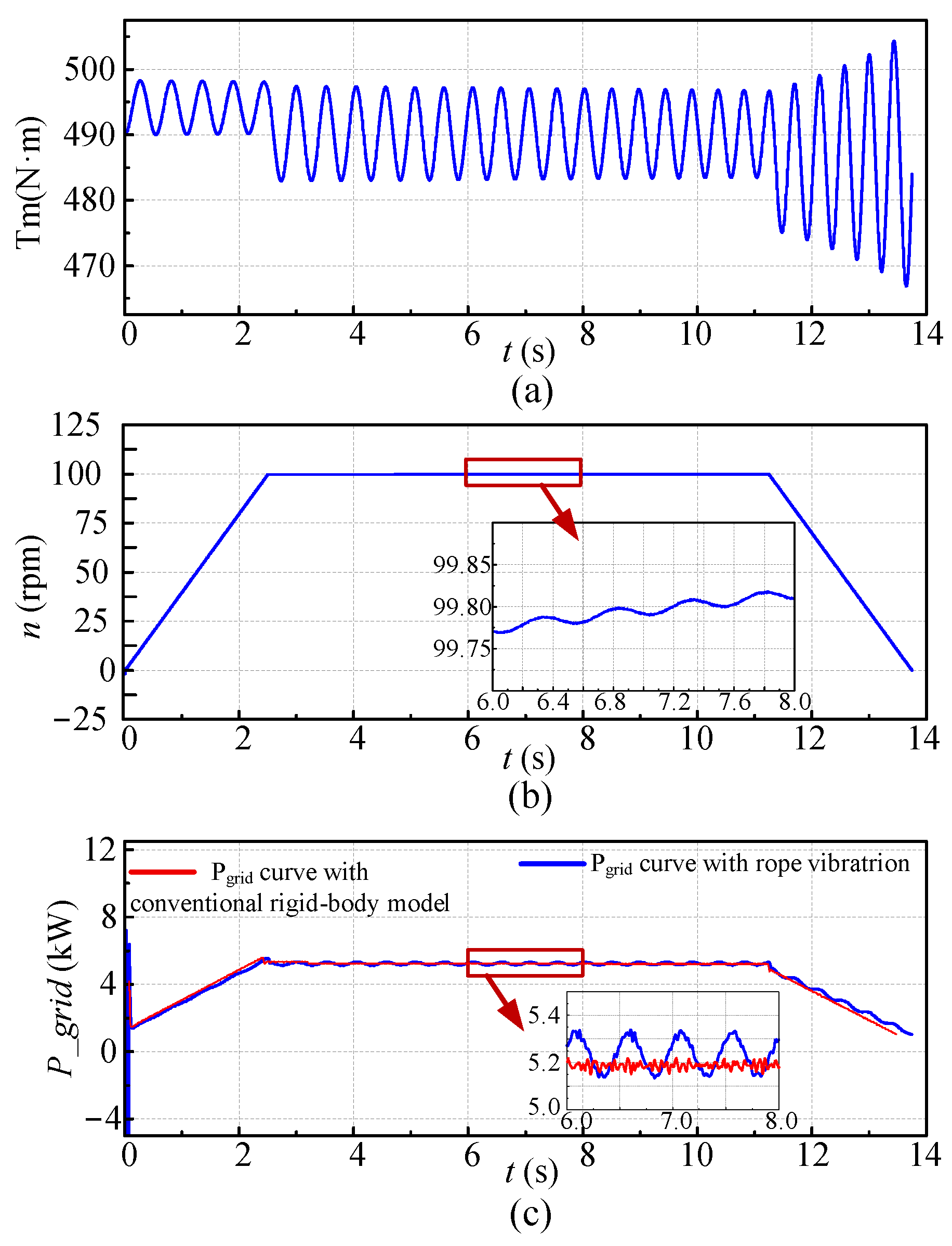
Figure 4a, Figure 4b and Figure 4c display the time-domain simulation waveforms of the mechanical load torque, rotational speed, and grid-side active power, respectively, thereby illustrating the dynamic characteristics of the GESS. Specifically, Figure 4c compares the power characteristics under two different modeling assumptions: the red curve represents the conventional model treating the hoisting system as an ideal constant load source, where the power output contains only high-frequency switching ripples; in contrast, the blue curve represents the proposed distributed-parameter model considering rope vibration, which clearly exhibits pronounced low-frequency beat power oscillations. This comparison conclusively demonstrates that the traditional ideal-load assumption fails to capture the critical low-frequency electromechanical oscillations affecting grid-connected power quality, whereas the proposed framework can accurately characterize this cross-domain dynamic response. In addition, Figure 4a reflects that the load torque exhibits periodic pulsations influenced by the elastic vibration of the flexible rope, while Figure 4b confirms that even under closed-loop regulation, mechanical disturbances still induce observable speed fluctuations during the steady-state phase.
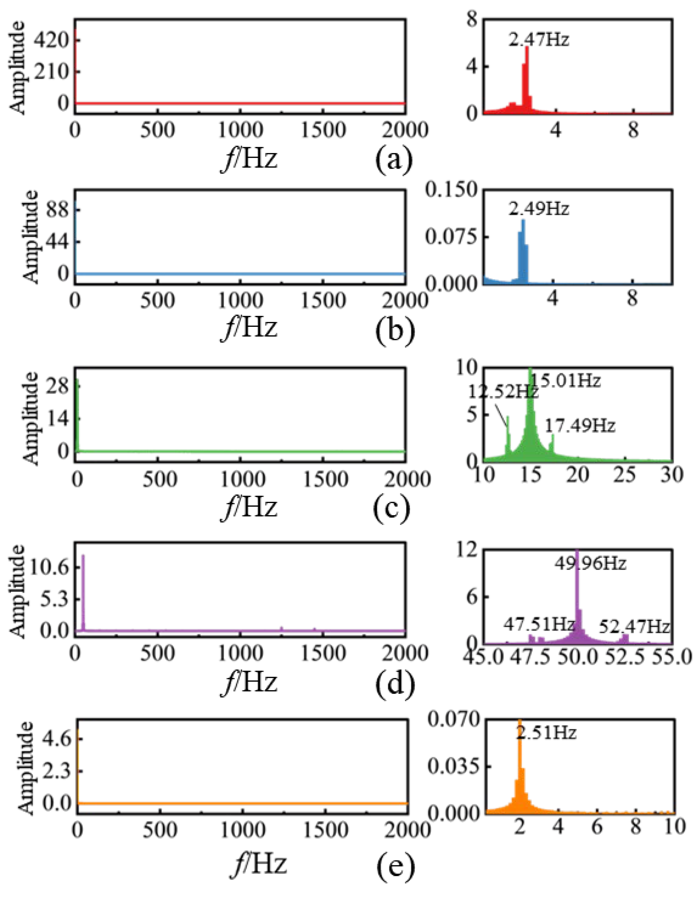
From a frequency-domain perspective, the Fast Fourier transform (FFT) comparison in Figure 5 illustrates the spectral characteristics of the key signals. In the tension spectrum (Figure 5a), a distinct primary peak corresponding to the natural frequency of the rope vibration is observed. When the wire rope vibrates around its static equilibrium state as the load is being lifted, its tension oscillations manifest as a clear spectral peak around 2.47 Hz. This vibration propagates through the mechanical load torque (Figure 5b), where a similar dominant frequency of 2.49 Hz can be observed, confirming that the periodic tension fluctuation directly influences the load torque. The motor-side current spectrum (Figure 5c) shows a symmetric distribution of harmonic clusters modulated around the fundamental frequency of 15.0 Hz and its vicinity (primarily at 12.52 Hz and 17.49 Hz), reflecting both the natural frequency of the rope and frequency components from motor speed fluctuations. The current spectrum reflects the complex dynamic response of the system, influenced not only by rope vibrations but also by the motor control strategy and mechanical system inertia. The grid-side current spectrum (Figure 5d) also displays a symmetric distribution of harmonic clusters modulated around the fundamental frequency of 50.0 Hz and its vicinity (primarily at 47.51 Hz and 52.47 Hz), indicating that vibration-induced current components are transmitted through the converter system to the grid interface. While some high-frequency components remain visible in the motor-side current, the grid-side current spectrum is relatively smooth, suggesting that the grid-side filtering and control process attenuates part of the high-frequency content while retaining low-frequency interharmonic components. Finally, the grid-side power spectrum (Figure 5e) shows a distinct peak around 2.51 Hz, indicating that fluctuations in rope tension and load torque modulate the power output. This spectral feature aligns with the characteristics observed in the motor-side current and further confirms the influence of rope vibration on the overall energy transfer process.
The above analysis demonstrates that during the operation of a GESS, the mechanical vibration of the flexible hoisting rope is transmitted through the winding drum and first manifests as periodic torque fluctuations acting on the driving motor. Through electromechanical energy conversion, these mechanical oscillations excite multi-band vibration components in the stator current, including frequencies close to the fundamental motor frequency. These characteristic frequency components are subsequently modulated by the dual-PWM converter on both the motor and grid sides, forming a low-frequency composite harmonic cluster containing interharmonics and subharmonics. This cluster is ultimately injected into the power system through the grid interface, resulting in observable current ripples and power oscillations on the grid side.

5. Results and Discussion

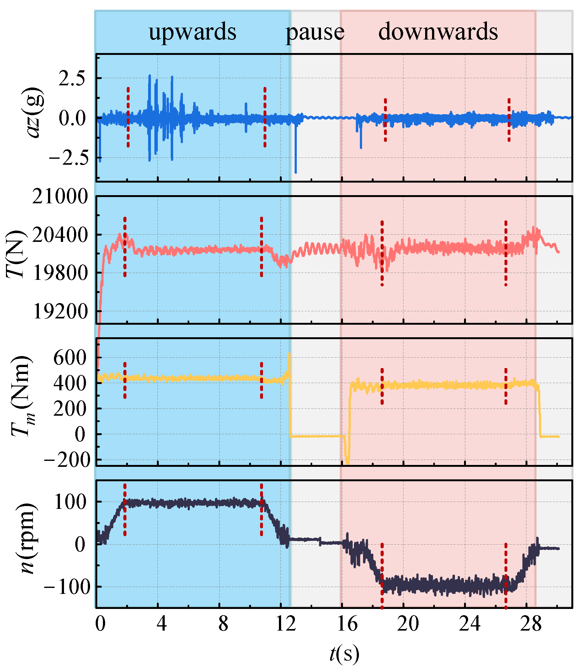
The test was conducted with the motor operating at a rated speed of 100 rpm. During the interval from 0 to 2.5 s, the motor started and accelerated the payload to steady-state operation. From 2.5 s to 10.5 s, the payload moved upward at a constant velocity. Once it reached the designated height, the motor speed was reduced to zero over the interval of 10.5 s to 12 s, during which the mechanical brake engaged to lock the shaft and hold the payload in suspension. Between 16.5 s and 18 s, the motor was commanded to accelerate in the reverse direction, followed by a deceleration to zero from 18 s to 20 s as the payload approached the ground. For the motor, a positive rotational speed corresponds to motoring operation, while for the payload, the upward vertical direction is defined as positive. As shown in Figure 6, the measured parameters during the complete operational cycle of the GESS are the load acceleration of the z-axis, wire rope tension, motor mechanical load torque, and motor velocity, respectively. The red dashed lines in the figure indicate the instants at which acceleration changes occur. During the ascent/descent process, it is divided into three parts: uniform acceleration, constant velocity, and deceleration.
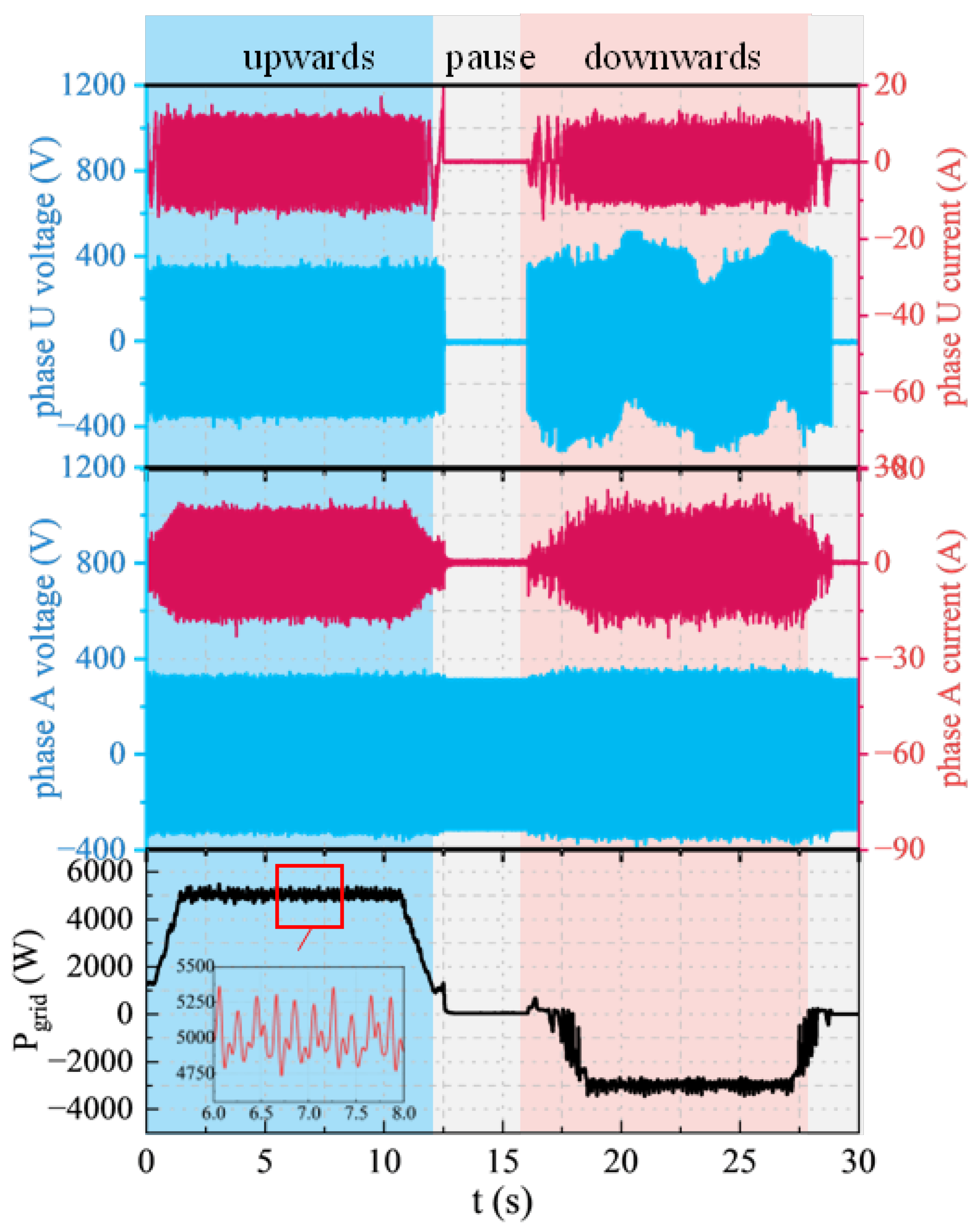
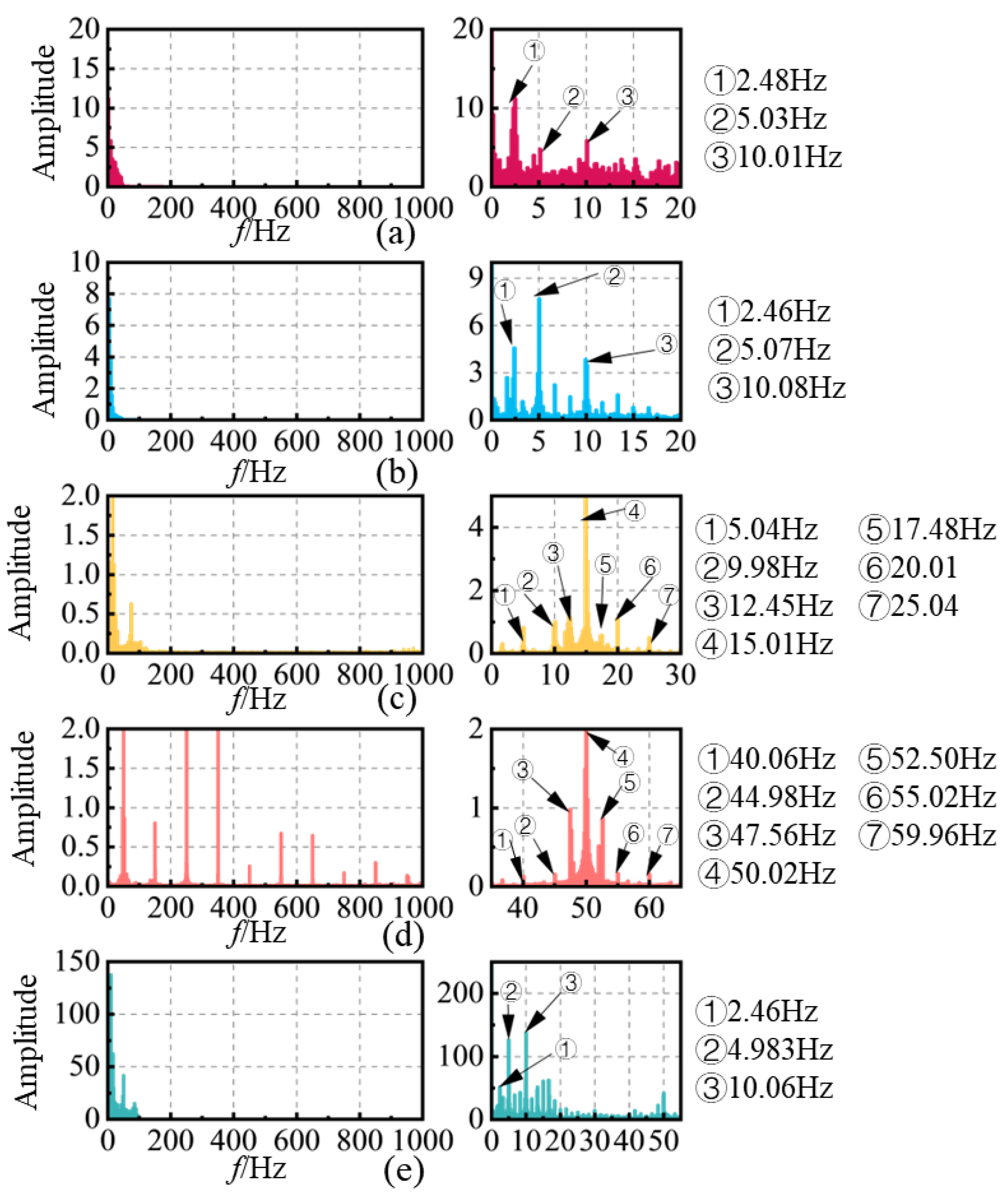
Figure 7 illustrates the measured electrical waveforms, depicting from top to bottom: the machine-side U-phase voltage and current, the grid-side A-phase voltage and current, and the grid-side power. The segmented curves clearly reveal that all measured parameters contain periodic low-frequency components during the stable constant-speed operation phases of both energy storage and release. To further isolate and compare these low-frequency components in the drive train parameters, we conducted FFT analysis on data segments from the stable energy storage phase. The resulting frequency domain distribution characteristics are shown in Figure 8.
Experimental data reveal three characteristic low-frequency energy concentrations in weight acceleration at around 2.5 Hz, 5 Hz, and 10 Hz. This mechanical vibration propagates through wire rope tension to the motor system, where it undergoes electromechanical energy conversion, generating electromagnetic oscillations containing (15 ± 2.5) Hz, (15 ± 5) Hz, and (15 ± 10) Hz interharmonics with 15 Hz as the fundamental frequency. Through modulation in the dual PWM converter system, the grid-connected side ultimately exhibits a spectral distribution centered at 50 Hz power frequency with characteristic sidebands at (50 ± 2.5) Hz, (50 ± 5) Hz, and (50 ± 10) Hz. The beat frequency effect causes primary grid power fluctuation frequencies to revert to original mechanical vibration bands (2.5 Hz, 5 Hz, 10 Hz), showing strong consistency with both the theoretical analysis in Section 3.2 and the simulation results. A quantitative assessment is conducted to evaluate this consistency: the relative error between the theoretical frequencies of the interharmonic sidebands and the measured spectral peaks is constrained within 2%, thereby quantitatively confirming the high fidelity of the analytical model.
Crucially, these generated interharmonic clusters are situated in proximity to the fundamental frequency. This proximity dictates that the resulting power oscillations are inherently difficult to isolate or mitigate from the grid interface using standard filtering techniques without compromising the fundamental energy transfer. According to international standards such as IEEE 519 [37] and IEC 61000 [38], these near-fundamental interharmonics can lead to detrimental effects such as voltage flicker and electromagnetic interference, and thus should be strictly minimized to the lowest possible levels.
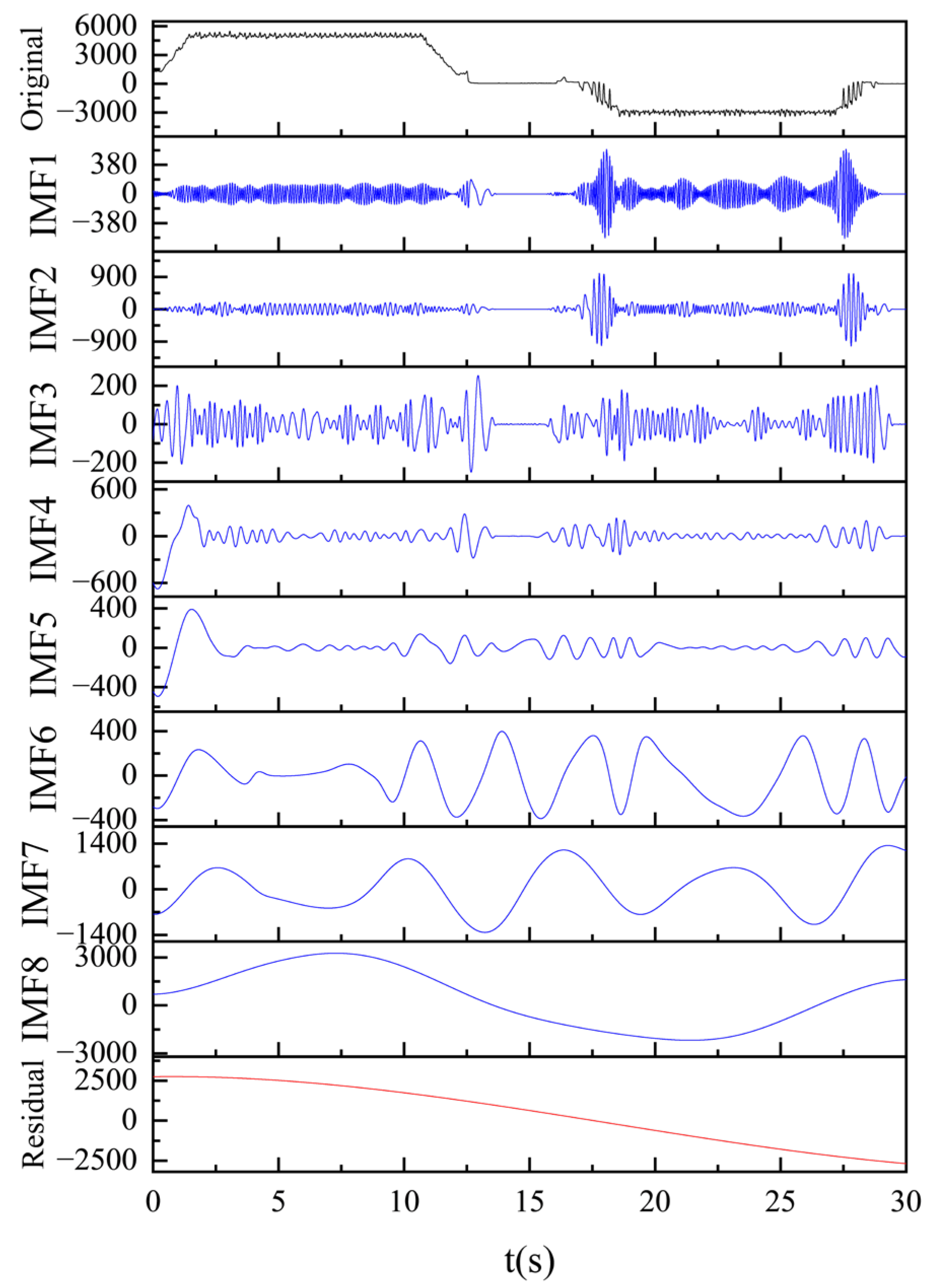
After implementing high-frequency noise suppression on the grid-side power signal, the time-domain waveform exhibits pronounced low-frequency oscillation characteristics. Employing Hilbert-Huang transform (HHT) for time-frequency analysis, Figure 9 demonstrates the empirical mode decomposition (EMD) results of the original signal, successfully extracting intrinsic mode functions (IMFs) that characterize the system’s dynamic behavior. To guarantee the physical validity of the decomposition, the EMD sifting process implements a standard Cauchy convergence criterion with a standard deviation threshold of 0.2, thereby preventing over-sifting and mitigating mode mixing.
The original non-stationary waveform is adaptively decomposed into eight intrinsic mode functions (IMF1–IMF8), covering a wide range of characteristic frequencies. Because the high-frequency switching and grid fundamental noises are pre-filtered, the first few IMFs directly capture the electromechanical dynamic behaviors. Statistical analysis of their instantaneous frequencies via the Hilbert transform reveals that IMF1, IMF2, and IMF4 exhibit core mean frequencies of approximately 10.08 Hz, 5.29 Hz, and 2.36 Hz, respectively. These adaptive modes closely correspond to the 10 Hz, 5 Hz, and 2.5 Hz mechanical vibration characteristics derived from the FFT analysis, confirming that IMF1 through IMF4 constitute the major sources of the observed power oscillations. IMF5 through IMF7 capture ultra-low-frequency local structural fluctuations (<1 Hz), while IMF8 represents the long-term trend associated with operating-state transitions, such as acceleration, steady motion, and deceleration.
Furthermore, the extraction of these low-frequency components exhibits robustness against the variation in system parameters. The GESS is inherently a time-varying system; during hoisting, the continuous decrease in wire rope length causes the equivalent mechanical stiffness to rise, driving a dynamic drift in the mechanical natural frequencies. Unlike fixed-basis spectral methods that struggle with non-stationary signals, the fully adaptive nature of EMD robustly tracks this parameter drift. The instantaneous frequency bandwidths of the extracted IMFs dynamically encompass these variations without requiring manual recalibration, demonstrating robustness against the time-varying spatial dynamics of the hoisting process.
To evaluate the practical relevance of the extracted results and quantitatively compare the oscillation magnitudes across different operating conditions, a modified power quality metric, the Low-Frequency Power Fluctuation Rate (LF-PFR), is proposed. Conventional metrics evaluate broad-spectrum variance and cannot accurately isolate non-stationary electromechanical dynamics. Based on the HHT analysis, the first four intrinsic mode functions (IMF1–IMF4) are identified as the dominant carriers of the mechanical-vibration-induced oscillations. The LF-PFR is defined as the root-mean-square (RMS) value of these aggregated low-frequency components normalized by the nominal active power PN:
LF - PFR = 1 P N 1 t 2 t 1 t 1 t 2 i = 1 4 I M F i ( t ) 2 d t × 100 %
By segmenting the operational cycle, the LF-PFR is calculated for three distinct kinematic states. The analytical results indicate an LF-PFR of 3.62% during the steady-state hoisting operation (2.5~10.5 s). During the transient acceleration phase (0~2.5 s), the LF-PFR intensifies significantly to 8.87%, driven by the severe initial tensioning of the flexible rope and the overcoming of mechanical inertia. During the deceleration phase (10.5~12 s), the LF-PFR registers at 4.33%. This quantitative comparison explicitly demonstrates that dynamic acceleration imposes the most severe excitation on the electromechanical coupled system, leading to amplified grid-side power oscillations. The proposed index provides a practical evaluation criterion for assessing the dynamic stability boundaries of GESS.
The above experimental results confirm both the existence and the underlying mechanism of low-frequency oscillations induced by mechanical vibrations in GESS. During system operation, the low-frequency mechanical vibration of the flexible hoisting rope is transmitted through the winding drum, where it is first transformed into periodic torque pulsations acting on the drive motor. This mechanical oscillation subsequently couples into the stator current through the electromechanical energy conversion process, exciting multiple frequency components in the vicinity of the fundamental grid frequency. These characteristic frequencies are then jointly modulated by the dual-PWM converter on both the machine-side and the grid-side, forming a low-frequency composite harmonic cluster containing interharmonics and subharmonics. Ultimately, this harmonic cluster is injected into the grid through the grid interface, resulting in pronounced current fluctuations and power oscillations on the grid side.
While the proposed analytical model and experimental validation rely on a scaled laboratory prototype with a relatively short wire rope, it is necessary to discuss the extension to full-scale deep-shaft applications. Under long-shaft conditions (e.g., up to a kilometer), the mechanical modeling must transition from a lumped-parameter approach to a distributed-parameter system governed by the wave equation, so as to account for the distributed mass of the wire rope and the propagation delay of longitudinal stress waves. Furthermore, as the rope mass scales to industrial levels (e.g., exceeding 20 tons), its dynamic behavior undergoes a fundamental transition. The massive equivalent inertia drives the fundamental natural frequency downward, though typically maintaining at or above 0.5 Hz, and significantly amplifies the participation factors of higher-order spatial modes. Unlike the laboratory prototype, where the fundamental mode strictly dominates, a full-scale GESS will exhibit complex multi-modal coupled oscillations.
A critical characteristic of a kilometer-scale GESS is the severe variation in mechanical stiffness with time. The equivalent stiffness of the wire rope is defined as K(t) = EA/L(t). During hoisting operations, as the rope length L(t) decreases from 1000 m to near zero, K(t) increases by orders of magnitude. Consequently, the mechanical natural frequency ωl(t) continuously drifts over a wide spectrum, effectively acting as a dynamic frequency sweep. This sweep heightens the risk of frequency-crossing resonance, which may align with VOC/Phase-Locked Loop (PLL) bandwidths, exacerbating power oscillations and potentially triggering protective tripping.
More importantly, despite the substantial dimensional disparities between the scaled prototype and industrial applications, the distributed-parameter modeling approach and the analytical computational framework developed in this study are universally applicable. The mathematical formulation natively accommodates the extreme mass, length, and multi-modal parameters of MW-class systems, and the fundamental mechanism translating mechanical perturbations into grid-side power oscillations via the beat-frequency effect remains strictly valid across arbitrary scales.

6. Conclusions and Perspectives

This study systematically reveals the fundamental mechanism through which mechanical vibrations in GESS propagate through the electromechanical chain and ultimately induce low-frequency oscillation dynamics on the grid side. By establishing a distributed-parameter dynamic model of the hoisting rope, deriving the longitudinal vibration characteristics under varying rope lengths, and analyzing the torque-current-power transmission pathway, the work demonstrates that the flexible rope’s low-frequency vibration is not a localized mechanical phenomenon but rather a source of multi-stage coupled oscillations. The mechanical tension fluctuations are propagated through the hoisting process, translated into periodic torque pulsations of the PMSM, and further mapped into multi-frequency current components through electromagnetic coupling. These components are subsequently modulated by the dual-PWM converter, giving rise to subharmonic and interharmonic clusters that are eventually injected into the grid, causing observable current ripple and power oscillation. The experimental results validate the analytical predictions and confirm the sensitivity of GESS to rope-induced mechanical disturbances throughout the entire operation cycle. These disturbances manifest as continuous harmonic injections during steady-state operation and become particularly pronounced during dynamic phases such as acceleration and deceleration. The findings highlight the importance of incorporating mechanical flexibility, electromechanical coupling, and converter interaction mechanisms into the stability assessment of GESS. They also underscore the necessity of developing vibration-aware control and grid-interaction strategies to ensure operational safety and power quality in practical applications.
Key future research priorities include:
  • Operational characteristics of MW-scale deep-shaft and ultra-deep-shaft GESS. While the strictly vertical, one-dimensional distributed-parameter model accurately captures the dynamics of the laboratory-scale prototype, its limitations will manifest in large-scale applications. In ultra-deep shafts, the vertical assumption neglects the catenary effect (rope sag) in the span between the hoist drum and head sheave, which introduces a nonlinear softening stiffness to the mechanical drivetrain. Furthermore, thick wire ropes used for heavy payloads exhibit significant bending stiffness and dynamic friction at the sheave interface, while the sagging inclined segments introduce strong transverse-longitudinal vibration coupling. Additionally, external environmental vibrations (e.g., seismic activity or aerodynamic buffeting) could act as parametric excitations. If these environmental frequencies synchronize with the dynamic natural frequencies of the rope, the resulting severe structural resonance could generate load torque ripples that exceed the bandwidth and saturation limits of the standard motor speed regulation, leading to a critical loss of electromechanical control. Future research must advance toward 3D multi-directional coupled models to accurately characterize these complex spatial dynamics alongside extremely long ropes and large payloads.
  • Development of a comprehensive stability framework for GESS electromechanical systems. Although industrial hoisting operations occasionally utilize external mechanical damping hardware, such as hydraulic floating sheaves, to mitigate vibrations, their integration significantly increases capital costs and control dimensionality. In the current verification stage, such external components were excluded to isolate intrinsic electromechanical dynamics. Future stability frameworks for MW-scale systems should incorporate techno-economic evaluations of auxiliary mechanical damping hardware, together with active anti-sway and low-frequency oscillation suppression strategies across wide operating conditions. Specifically, as the dynamic frequency sweep progresses toward the top of the shaft, the extreme short-rope condition causes a sharp increase in natural frequency. In this state, potential resonance with the motor spatial harmonics and cogging effects may significantly exacerbate high-frequency electromechanical oscillations. Therefore, future research should explicitly evaluate whether tailored hardware damping solutions are required to mitigate short-rope high-frequency coupling, while also developing active anti-sway and low-frequency oscillation suppression strategies across broad operating ranges. Based on the identified transmission pathway, the development of these active suppression strategies should prioritize the torque/current control loop, such as the q-axis current reference, as the optimal damping-injection point. Its high bandwidth enables near-zero-delay tracking for direct electromagnetic torque compensation, effectively acting as an active shock absorber against rope-induced disturbances without compromising the primary speed-tracking profile.
  • Grid-interactive behavior of large-scale GESS, covering harmonic mitigation, coordinated control with renewable energy sources, and system-level modeling under high-penetration scenarios.
These directions will provide the theoretical basis for advancing next-generation large-scale gravity energy storage technologies and serve as essential support for ensuring their safe, stable, and high-quality grid-connected operation.

Author Contributions

Conceptualization, X.L., Q.Q. and L.X.; methodology, X.L., Y.C. and L.X.; software, X.L.; validation, Y.L. and L.J.; formal analysis, Q.Q.; investigation, Y.L., L.D. and Y.C.; data curation, L.J.; writing—original draft preparation, X.L.; writing—review and editing, Q.Q., L.D., Y.C. and L.X.; visualization, L.J.; supervision, L.X. All authors have read and agreed to the published version of the manuscript.

Funding

This work was supported by CHN Energy Investment Group (GJNY-24-92) and Institute of Electrical Engineering and Advanced Electromagnetic Drive Technology, Qilu Zhongke scientific research fund project (Research on key technologies of gravitational potential energy storage).

Data Availability Statement

The original contributions presented in this study are included in the article. Further inquiries can be directed to the corresponding author.

Conflicts of Interest

Authors Li Dong and Yanqiao Chen were employed by the company CHN Energy New Energy Technology Research Institute Co., Ltd. The remaining authors declare that the research was conducted in the absence of any commercial or financial relationships that could be construed as a potential conflict of interest.

Abbreviations

The following abbreviations are used in this manuscript:
GESSGravity energy storage system
NVHNoise, vibration, harshness
MMFMagnetomotive force
PWMPulse-width modulation
FFTFast Fourier transform
HHTHilbert-Huang transform
EMDEmpirical mode decomposition
IMFIntrinsic mode functions

Appendix A. Mass Matrix, Damping Matrix, Stiffness Matrix, and Generalized Force Matrix of the Generalized Coordinate Vector X

M i j = ρ 0 1 ϕ i ξ ϕ j T ξ d ξ + M l ( t ) ϕ i 1 ϕ j T 1
K i j = 3 4 ρ l ˙ 2 ( t ) l 2 ( t ) ρ l ˙ ¨ ( t ) 2 l ( t ) 0 1 ϕ i ξ ϕ j T ξ d ξ + 2 ρ l ˙ 2 ( t ) l ( t ) 0 1 ξ ϕ i ξ ϕ j T ξ d ξ 3 ρ l ˙ 2 ( t ) l ( t ) 0 1 ϕ i ξ ϕ j T ξ d ξ ρ l ˙ 2 ( t ) l 2 ( t ) k 0.5 π 2 0 1 1 ξ 2 ϕ i ξ ϕ j T ξ d ξ + ρ l ¨ ( t ) 0 1 1 ξ 2 ϕ i ξ ϕ j T ξ d ξ + E A l 2 ( t ) 0 1 k 0.5 π 2 ϕ i ξ ϕ j T ξ d ξ + M 3 4 l ˙ 2 ( t ) l 3 ( t ) 1 2 l ˙ ¨ ( t ) l 2 ( t ) ϕ i 1 ϕ j T 1 μ E A 5 2 l ˙ ( t ) l 3 ( t ) 0 1 k 0.5 π 2 ϕ i ξ ϕ j T ξ d ξ μ E A l ˙ ( t ) l 2 ( t ) k 0.5 π 2 0 1 ξ ϕ i ξ ϕ j T ξ d ξ
C i j = ρ l ˙ ( t ) l ( t ) 0 1 ϕ i ξ ϕ j T ξ d ξ + 2 ρ l ˙ t 0 1 1 ξ ϕ i ξ ϕ j T ξ d ξ + μ E A l 2 ( t ) k 0.5 π 2 0 1 ϕ i ξ ϕ j T ξ d ξ M l ˙ ( t ) l 2 ( t ) ϕ i 1 ϕ j T 1
P n × 1 = 1 l ( t ) ρ l ¨ ( t ) 0 1 ϕ i ( ξ ) d ξ M l ( t ) l ¨ ( t ) ϕ i ( 1 )

Appendix B. Bessel Function of the First Kind

F 1 ( ω I , ω F ) = 3 M B F 4 [ cos ( ω I t ω F t ϕ Z + ϕ Z 0 ) ]
F 2 ( ω I , ω F k , ω C ) = 2 2 I A O M D p , q π cos ( ω I t ϕ Z ) cos [ ( q ω I + p ω C ) t ] + 2 M B D p , q π cos ( ω F t ϕ Z F ) cos [ ( q ω I + p ω C ) t ] + 2 2 I B O M D p , q π cos ( ω I t 2 π 3 ϕ Z ) cos { [ q ( ω I 2 π 3 ) + p ω C ] t } + 2 M B D p , q π cos ( ω F t 2 π 3 ϕ Z F ) cos { [ q ( ω I 2 π 3 ) + p ω C ] t } + 2 2 I C O M D p , q π cos ( ω I t + 2 π 3 ϕ Z ) cos { [ q ( ω I + 2 π 3 ) + p ω C ] t } + 2 M B D p , q π cos ( ω F t + 2 π 3 ϕ Z F ) cos { [ q ( ω I + 2 π 3 ) + p ω C ] t }
D p , q = p = 1 q = 1 1 p J n ( π 2 p M ) sin [ ( p + q ) π 2 ]

References

  1. Yu, H.; Yao, L.; Cheng, F.; Li, Y.; Zhai, W.; Wang, Q. Prospects and Challenges of Gravity Energy Storage Applications in New Type Power System. Proc. CSEE 2025, 45, 7177–7193. [Google Scholar]
  2. Thomas, M.; Martin, C.; Malcom, D. Gravity energy storage with suspended weights for abandoned mine shafts. Appl. Energy 2019, 239, 201–206. [Google Scholar] [CrossRef]
  3. Cathleen, O. Gravity powers batteries for renewable energy. Science 2021, 372, 446. [Google Scholar] [CrossRef]
  4. Wang, S.; Xiao, L.; Tang, W.; Zhang, J.; Qiu, Q.; Guo, W.; Zhang, D. Research review on new gravity energy storage. Energy Storage Sci. Technol. 2022, 11, 1575–1582. [Google Scholar]
  5. Advanced Rail Energy Storage (ARES). Available online: https://aresnorthamerica.com/ (accessed on 1 April 2026).
  6. Julian, D.H.; Behnam, Z.; Giacomo, F.; Andreas, N.; Yoshihide, W.; Keywan, R. Mountain Gravity Energy Storage: A new solution for closing the gap between existing short- and long-term storage technologies. Energy 2020, 190, 116419. [Google Scholar] [CrossRef]
  7. Luo, Z.; Huang, T.; Mei, J.; Niu, W.; Yang, F. Gravity Energy Storing System Relying on Massif. CN103867408A, 18 June 2014. [Google Scholar]
  8. Xiao, L.; Shi, L.; Wei, T.; Han, L. Railway Track Carrier Vehicle Energy Storage System. CN108437808A, 24 August 2018. [Google Scholar]
  9. Guo, G.; Zha, K.; Zhou, L.; Luan, H.; Li, Q.; Zhao, C. Efficient Gravity Energy Storage System Based on Conveying Chain. CN112096580A, 18 December 2020. [Google Scholar]
  10. Energy Vault. Available online: https://energyvault.com/ (accessed on 1 April 2026).
  11. Tong, W.; Lu, Z.; Zhao, H.; Han, M.; Zhao, G.; Julian, D.H. The structure and control strategies of hybrid solid gravity energy storage system. J. Energy Storage 2023, 67, 107570. [Google Scholar] [CrossRef]
  12. Haider, S.; Shahmoradi, M.H.; Schönberger, J.; Schegner, P. Algorithm and Optimization Model for Energy Storage Using Vertically Stacked Blocks. IEEE Access 2020, 8, 217688–217700. [Google Scholar] [CrossRef]
  13. Emrani, A.; Berrada, A.; Ameur, A.; Bakhouya, M. Assessment of the round-trip efficiency of gravity energy storage system: Analytical and numerical analysis of energy loss mechanisms. J. Energy Storage 2022, 55, 105504. [Google Scholar] [CrossRef]
  14. Kropotin, P.; Marchuk, I. On efficiency of load-lifting rope-traction mechanisms used in gravity energy storage systems. J. Energy Storage 2023, 58, 106393. [Google Scholar] [CrossRef]
  15. Yi, Y.; Qin, D.; Liu, C. Investigation of electromechanical coupling vibration characteristics of an electric drive multistage gear system. Mech. Mach. Theory 2018, 121, 446–459. [Google Scholar] [CrossRef]
  16. Chen, R.; Qin, D.; Yi, Y.; Liu, C.; Shi, J. Dynamic characteristics of electromechanical coupling of wind turbine drive system under multi-source excitation. Wind Energy 2022, 25, 391–418. [Google Scholar] [CrossRef]
  17. Hu, J.; Yang, Y.; Jia, M.; Guan, Y.; Peng, T. A Novel Energy Optimization Control Strategy for Electric Drive System Based on Current Angle. Appl. Sci. 2020, 10, 3778. [Google Scholar] [CrossRef]
  18. Wang, Q.; Rajashekara, K.; Jia, Y.; Sun, J. A Real-Time Vibration Suppression Strategy in Electric Vehicles. IEEE Trans. Veh. Technol. 2017, 66, 7722–7729. [Google Scholar] [CrossRef]
  19. Chen, X.; Zhu, Z.; Li, W.; Shen, G. Fault-Tolerant Control of Double-Rope Winding Hoists Combining Neural-Based Adaptive Technique and Iterative Learning Method. IEEE Access 2019, 7, 50476–50491. [Google Scholar] [CrossRef]
  20. Chen, X.; Zhu, Z.; Li, W. Tension coordination control of double-rope winding hoisting system using hybrid learning control scheme. Proc. Inst. Mech. Eng. Part I J. Syst. Control Eng. 2019, 233, 1265–1281. [Google Scholar] [CrossRef]
  21. Zhu, Z.; Li, X.; Shen, G.; Zhu, W. Wire rope tension control of hoisting systems using a robust nonlinear adaptive backstepping control scheme. ISA Trans. 2018, 72, 256–272. [Google Scholar] [CrossRef]
  22. Gaiko, N.V.; Van, H.W.T. Resonances and vibrations in an elevator cable system due to boundary sway. J. Sound Vib. 2018, 424, 272–292. [Google Scholar] [CrossRef]
  23. Nguyen, T.X.; Miura, N.; Sone, A. Analysis and control of vibration of ropes in a high-rise elevator under earthquake excitation. Earthq. Eng. Eng. Vib. 2019, 18, 447–460. [Google Scholar] [CrossRef]
  24. Zhang, Q.; Hou, T.; Zhang, R.-J.; Liu, J. Time-varying Characteristics of the Longitudinal Vibration of a High-speed Traction Elevator Lifting System. Int. J. Acoust. Vib. 2020, 25, 153–161. [Google Scholar] [CrossRef]
  25. Kandil, A.; Francis, C.A.; Elsaid, A.; Zahra, W.K. Effect of the suspended block’s weight on the nonlinear dynamics of a non-ideal magnetic levitation model connected to an energy harvester. Int. J. Non-Linear Mech. 2025, 170, 104974. [Google Scholar] [CrossRef]
  26. Young, M.; Rajesh, R. Identification and experimental validation of a scalable elevator vertical dynamic model. Control. Eng. Pract. 2001, 9, 181–187. [Google Scholar]
  27. Fung, R.F.; Wang, P.H.; Lee, M.J. Nonlinear vibration analysis of a traveling string with time-dependent length by finite element method. J. Chin. Inst. Eng. 2011, 21, 109–117. [Google Scholar] [CrossRef]
  28. Roberts, R. Control of high-rise/high-speed elevators. In Proceedings of the 1998 American Control Conference. ACC (IEEE Cat. No.98CH36207); IEEE: New York, NY, USA, 1998; pp. 3440–3444. [Google Scholar]
  29. Yao, C.; Fung, R.; Tseng, C. Non-linear vibration analysis of a travelling string with time-dependent length by new hybrid laplace transform/finite element method. J. Sound. Vib. 1999, 219, 323–337. [Google Scholar] [CrossRef]
  30. Arakawa, A.; Miyata, K. A variable-structure control method for the suppression of elevator-cage vibration. In IEEE 2002 28th Annual Conference of the Industrial Electronics Society. IECON 02; IEEE: New York, NY, USA, 2002; Volume 3, pp. 1830–1835. [Google Scholar]
  31. Öz, H.R. Current research on the vibration and stability of axially moving materials. J. Sound Vib. 2002, 259, 445–456. [Google Scholar] [CrossRef]
  32. Kimura, H.; Ito, H.; Fujita, Y. Forced vibration analysis of an elevator rope with both ends moving. J. Vib. Acoust. 2007, 129, 471–477. [Google Scholar] [CrossRef]
  33. Zhang, P.; Bao, J.; Zhu, C. Dynamic analysis of hoisting viscous damping string with time-varying length. J. Phys. Conf. Ser. 2013, 488, 012011. [Google Scholar] [CrossRef]
  34. Bao, J. Study on Dynamic Modeling and Vibration Control Method of High-Speed Elevator Hoisting System. Ph.D. Thesis, Shanghai Jiao Tong University, Shanghai, China, 2014. [Google Scholar]
  35. Yang, D.; Yang, W.; Li, R. Modeling for Coupling Modulation in Dual PWM Speed Control Systems and Characteristic Analysis of Interharmonic Currents Injected into Distribution Networks. Proc. CSEE 2017, 37, 869–880. [Google Scholar]
  36. Chen, X. Study on Electromechanical Coupling Nonlinear Vibration of Electromechanical Transmission System for HEV. Ph.D. Thesis, Beijing Institute of Technology, Beijing, China, 2015. [Google Scholar]
  37. IEEE Std 519-2022; IEEE Standard for Harmonic Control in Electric Power Systems. IEEE: New York, NY, USA, 2022.
  38. IEC 61000-4-7:2002; Electromagnetic Compatibility (EMC)—Part 4-7: Testing and Measurement Techniques—General Guide on Harmonics and Interharmonics Measurements and Instrumentation, for Power Supply Systems and Equipment Connected Thereto. International Electrotechnical Commission: Geneva, Switzerland, 2002.
Figure 1. Gravity energy storage hoisting system vertical oscillation model.
Energies 19 02568 g001
Figure 2. Hoisting systems: (a) Motion pattern; (b) Natural frequencies.
Energies 19 02568 g002
Figure 3. Gravity Energy Storage Laboratory Prototype System Architecture.
Energies 19 02568 g003
Figure 4. System grid-side curves: (a) Mechanical torque; (b) Rotational speed; (c) Grid-side power.
Energies 19 02568 g004
Figure 5. Frequency spectrum of key parameters: (a) Rope tension; (b) Mechanical load torque; (c) Motor-side current; (d) grid-side current; (e) grid-side power.
Energies 19 02568 g005
Figure 6. Mechanical measured curves of the GESS.
Energies 19 02568 g006
Figure 7. Electrical measured curves of the GESS.
Energies 19 02568 g007
Figure 8. Frequency spectrum of key parameters in experiments of: (a) az; (b) tension; (c) Iu; (d) Ia; (e) Pgrid.
Energies 19 02568 g008
Figure 9. EMD processing results of the grid-side power waveform.
Energies 19 02568 g009
Table 1. Wire Rope-Load Hoisting System Parameters.
ParameterValueParameterValue
Initial rope length (m)6 mLoad mass (kg)2500
Wire rope linear density (kg/m)0.6 kg/mWire rope elastic modulus (Pa)6 × 10⁹
Wire reel radius (m)0.1Wire rope cross-sectional area (m2)3.3 × 10⁻⁴
Torsional stiffness of rotating body5 × 107Wire rope damping factor(N·s/m)0.005
Table 2. Gravity Energy Storage Prototype System Parameters.
ComponentParameterValue
LoadWeight (kg)2000
Constant speed phase velocity (m/s)0.2
Stabilized power output (kW)3.92
Maximum displacement (m)4.5
Wire reelRadius (m)0.2
Wire rope diameter (mm)20
GearboxGear ratio5:1
Rated input torque (N·m)400
Rated output torque (N·m)2000
Motor/generatorRated speed (rpm)100
Rated torque (N·m)700
Rated power (kW)7.5
Number of pole pairs9
Four-quadrant inverterRated power (kW)11
DC-link voltage700 V
Switching carrier frequency1 kHz
Grid-side carrier ratio20
Machine-side carrier ratio66.67
Nominal modulation index0.89
ShaftTotal height (m)4.5
Disclaimer/Publisher’s Note: The statements, opinions and data contained in all publications are solely those of the individual author(s) and contributor(s) and not of MDPI and/or the editor(s). MDPI and/or the editor(s) disclaim responsibility for any injury to people or property resulting from any ideas, methods, instructions or products referred to in the content.