


Abstract
The integration of renewable energy sources (RESs) into modern power systems has introduced significant challenges in maintaining system stability and reliability. Among these challenges, load frequency control (LFC) has become a vital area of research. The variable nature of RESs, such as wind and solar, along with their intermittent availability, necessitates advanced management systems for effective frequency regulation. LFC plays a crucial role in ensuring the stability and performance of electrical power systems by managing frequency through the balance of supply and demand, accounting for variations in load, generation, and other disturbances within the system. In traditional power systems, LFC is achieved through a combination of primary, secondary, and tertiary control mechanisms. However, the advent of smart grids has considerably complicated and enhanced the potential for LFC. In these smart grids, which leverage digital communication, sensors, and automation technologies, LFC becomes more intricate and adaptable. These systems not only utilize traditional centralized control but also incorporate RESs, decentralized resources, energy storage solutions, and real-time data to improve frequency management. This research methodically evaluates current LFC techniques using a hierarchical control and technology-focused framework, classifying approaches as conventional, intelligent, and hybrid control schemes within centralized and decentralized system architectures. An evaluative analysis reveals that while intelligent and hybrid control strategies markedly enhance dynamic frequency response and robustness with substantial renewable energy source (RES) integration, persistent challenges remain regarding controller coordination, scalability, computational requirements, and real-time execution. The analysis highlights adaptive hybrid intelligent control schemes, namely those that combine data-driven learning with physical system models, as the most promising avenue for future research, particularly in low-inertia and highly dispersed smart grid scenarios.
1. Introduction
Energy is essential for the socioeconomic progress of countries and is a vital component of the Sustainable Development Goals (SDGs) [1,2]. Situated in the southern part of Africa, South Africa has a population of over 59 million and an average yearly growth rate of 1.43% [3]. The increasing population consistently pressures the power system infrastructure due to increasing energy demands [4,5]. Historically, South Africa’s electrical grid has been heavily dependent on coal-fired thermal plants. Given the adverse effects of fossil fuels and the growing environmental concerns over greenhouse gas emissions (GHGs), a rapid transformation is occurring in modern electrical power systems, with the integration of renewable generation and the introduction of smart grid technologies [6].
In addition, the overall stability of the power system requires matching the power demand with the total power generation and associated power losses. Technically, the operating parameters, such as voltage, frequency, etc., at connecting points between power generation and demand may oscillate if the matching is not met; hence, the electrical distribution system would experience frequency and power deviations to different areas; this may yield undesirable effects. Indeed, frequency sag occurs when the generated power output is inadequate to satisfy the load demand. Similarly, when the demand is reduced and the power output is increased, the frequency exhibits an overshoot at the demand side [7,8].
Renewable Distributed Generations (RDGs), like solar and wind systems, have gotten a lot of attention as a possible way to meet the world’s energy needs because they are easy to find and good for the environment. The load frequency control (LFC) method has been used for maintaining stable system frequency in power systems integrated with renewable energy sources; the LFC ensures a balance between demand and the generation system [9]. The standard grid code has established the technical standards for connecting RDGs into a power system. These requirements aim to guarantee the safe, secure, efficient and stable operation of the whole power system. As part of the grid code specifications, there are limits on parameters like voltage variation , frequency variation , voltage and current total harmonic distortion (i.e., and power factor ) [10].
Various frequency management technologies have been discussed in the literature for maintaining the grid’s frequency within the specified operational range. In research work [11], the authors introduced a method called cascaded enhanced active disturbance rejection control (ADRC). The suggested strategy, however, exhibits constrained capacity to manage nonlinearities and rapid operational changes in systems incorporating renewable energy sources (RESs). The performance is significantly dependent on the accuracy of the model. In research work [12], the authors introduced interval type-2 fuzzy inference systems (IT2FIS) and fractional-order calculus. This method is too reliant on computation and complexity; it faces issues in modeling and parameterizing controller sets and rules, exhibits poor interpretability, and is sensitive to tuning parameters. The authors in [13], presented adaptive high-order sliding mode control (HOSMC). However, this technique is restricted in its flexibility and application to nonlinear systems, as well as being very susceptible to uncertainties and fluctuations in system characteristics.
The LFC is a method implemented by power operators in modern power systems to manage the balance between generation and demand and, thus, to maintain the system frequency at its acceptable level at buses. To achieve this, the parameters of LFC in each control area should be tuned optimally for suitable performance. Several studies have used the fuzzy logic control (FLC)-based LFC for power system stability, e.g., in [14,15,16], due to its ability to handle nonlinearities and uncertainties. However, this method presents several limitations, such as the fact that the FLC may not provide the inertia response needed during disturbances, necessitating supplementary control strategies. The FLC can struggle with extreme load changes, requiring additional mechanisms to enhance robustness. On the other hand, the governor droop control (GDC) approach can achieve satisfactory control performance and can provide virtual inertia and damping properties and contribute to both transient and steady-state frequency regulation. However, the unpredictability of variable wind speed complicates this implementation [17,18]. Consequently, combining the FLC and GDC methods to form a hybrid controller (FLCGDC) can achieve satisfactory control performance at the point of common coupling (PCC) between power systems and renewable energy generation. The authors in [19] and [20] have conducted a research study on the hybrid control of traditional droop control and fuzzy logic control. The authors’ results indicate that the voltage and frequency error levels at the PCC were reduced using FLDC in comparison to GDC. Nonetheless, this low variance presents an opportunity for enhancement of the suggested FLDC approach. Therefore, we need to implement an efficient control strategy and avoid any deviations.
A robust controller would be capable of achieving a zero steady-state error for frequency deviations, good tracking for load demands, acceptable overshoot and settling time on the frequency and tie line power deviations. A poorly crafted dynamic control strategy can result in heightened frequency fluctuations, instability within the system, and potential blackouts when there is a significant integration of RDGs/wind farms. The paper is organized as follows: 1. Introduction, 2. Primary Frequency Control, 3. Secondary LFC for Unique Power System Design: Incorporating RESs, 4. LFC Strategy for Traditional Power System, 5. LFC Scheme Evaluating Wind-Integrated Power System, 6. Intelligent and Hybrid Control Techniques for Frequency Regulation in WECS, 7. Recommendations, 8. Conclusions.
Impact of Wind Turbine in a Power System
The rapid incorporation of renewable energy sources (RESs), especially wind generation, into contemporary power networks has fundamentally transformed system frequency dynamics and presented considerable challenges to sustaining operational stability. In contrast to traditional synchronous generators, wind turbines connected via power electronic converters have little or no intrinsic inertia, resulting in reduced system damping and increased susceptibility to disturbances. Consequently, frequency fluctuations resulting from load alterations, generation failures, or network disturbances have grown increasingly evident, particularly in systems with significant wind integration or frail grid attributes [21,22].
Empirical operational experiences have shown that traditional LFC techniques are progressively insufficient under these circumstances. For instance, abrupt increases in wind power or fault-induced disconnections of substantial wind farms may result in significant frequency dips and elevated rates of change of frequency (ROCOFs), often triggering under-frequency load-shedding mechanisms or leading to the malfunction of protection systems. Such occurrences are especially crucial in weak grids and islanded or low-inertia systems, where conventional governor-based primary control lacks the necessary speed and agility to address rapid power imbalances. These situations underscore the pressing need for sophisticated LFC methods that can adeptly address the stochastic and nonlinear attributes resulting from extensive wind integration. In this context, LFC is fundamental to power system functioning, tasked with maintaining the equilibrium between generation and demand, as well as reinstating system frequency after disruptions. Although classic hierarchical control structures—consisting of primary, secondary, and tertiary control—have shown efficacy in conventional power systems, their effectiveness diminishes in renewable-dominated smart grids. The growing implementation of distributed energy resources, energy storage systems, and advanced communication infrastructures requires increasingly flexible, decentralized, and smart solutions for load frequency control that can function successfully across diverse system sizes and operational situations [23,24].
This study offers a thorough assessment of LFC techniques within the framework of contemporary smart grids, which are characterized by significant renewable integration. The paper methodically analyses traditional, intelligent, and hybrid control methodologies, focusing specifically on their relevance to wind-integrated and low-inertia power systems. Identified key constraints of current approaches include challenges in controller coordination, scalability, computational complexity, and real-time implementation, consequently prompting new research avenues.
2. Primary Frequency Control (PFC)
Primary frequency control is applicable to diverse microgrid topologies utilizing synchronous generators. The implementation of this technique within wind energy conversion systems (WECSs) poses distinct issues due to the stochastic characteristics of wind, restricted intrinsic inertia, and converter-dominated interfaces. Consequently, this section will examine the fundamental concepts of primary frequency control to determine their use in wind energy conversion systems (WECSs) for primary frequency regulation by pitch angle adjustment.
Primary control can be classified into two main categories: communication-dependent methods and those that function without communication. Communication-dependent methods provide various advantages, such as accurate power distribution, high-quality power, effective transient response, and the prevention of circulating currents. However, these methods come with increased costs and complexities, requiring high-bandwidth communication links for control loops. In contrast, non-communication methods utilize droop control, which relies on local measurements to regulate distributed generation units. These methods offer several benefits, including adaptability, scalability, reliability, and ease of implementation. Nonetheless, droop control methods face challenges, such as uneven power distribution, sluggish transient response, and circulating currents among inverters. To mitigate these issues, various modifications to the traditional droop characteristics have been suggested. Figure 1 depicts the classification of the primary control types for an isolated microgrid [25].
Figure 1.
Primary control for islanded microgrid.
2.1. Communication-Based Primary Frequency Control (PFC)
Communication-based methods for primary control offer excellent voltage regulation and efficient power distribution. In contrast to droop-based techniques, which will be discussed later, these methods maintain output voltage and frequency close to their nominal levels without requiring secondary control. However, these control strategies depend on communication links between inverters, which increase the overall system cost. Additionally, the extended communication infrastructure can reduce the system’s reliability and scalability. The subsequent subsections will outline various standard communication-based methods for primary control.
2.1.1. Centralized-Control PFC Strategy
The centralized-control strategy requires the integration of current-sharing modules along with synchronization signals. Each distributed generation unit is equipped with a phase-locked loop (PLL) that ensures alignment of the output voltage phase, frequency, and synchronization signal. The current-sharing module assesses the total load and determines the reference current for each distributed generation unit. The reference current, , is dependent on the capacity of each distributed generation unit and corresponds to a fraction of the load current, . For () inverter-based distributed generation units, the reference current is calculated as follows:
This method facilitates effective current distribution during both steady-state and transient scenarios. However, this control technique requires a centralized controller, which reduces system redundancy and complicates expansion efforts. Furthermore, high-bandwidth communication links are necessary to relay synchronization pulses and reference currents to the inverters. This reliance on communication systems can lead to significant costs and pose risks of single-point failures, ultimately affecting overall reliability [26].
In a research study [27], the authors introduced a centralized method for primary frequency control utilizing electric vehicles as adjustable units. The testing is done in a separate system that only uses renewable energy sources. The main goal is to make sure that the frequency values stay within the allowed range even when the load changes or the wind power changes. The suggested technique exhibited superior performance for the total response delay. Nevertheless, the present undershooting was somewhat greater, and voltage deviations were noted. Furthermore, the precision of the existing limiting feature must be more effectively used to mitigate the undershooting.
The research study [28], presents a framework for distributed cooperation within a wind farm that employs a doubly fed induction generator (DFIG), focusing on primary frequency regulation. This framework aims to replicate the inertia and droop characteristics typical of conventional power plants. Unlike centralized systems, this method significantly improves control efficiency. To facilitate swift distributed coordination and effective power distribution among wind turbines, a distributed Newton method has been devised. This method requires wind turbines to share only minimal information with neighboring units via a sparse communication network, while also achieving a superlinear convergence rate. By utilizing a state of energy index, this strategy effectively captures the kinetic energy of all wind turbines while adhering to safety protocols. Simulation results indicate that this approach exhibits strong dynamic performance and reliability. The system frequency stabilizes more rapidly when the proposed method is employed for frequency control in the wind farm. The distributed strategy shows markedly enhanced dynamic performance and reliability compared to centralized systems, ensuring consistent energy states across all wind turbines.
In [29], the authors present a centralized management system specifically developed for electric water heaters in areas with substantial renewable energy integration, intended to address the imbalances between energy generation and demand within the regulated region. Nevertheless, the suggested approach does not fully handle the problem of peak power exports and imports. Consequently, the system continues to experience load fluctuations that result in deviations from rated values, indicating potential for improvement.
In [30], the authors concentrate on the capability of a wind farm controller to oversee the production levels of the wind farm. The aim is to develop a central controller that can regulate both the active and reactive power supplied by the entire wind farm to the grid, in accordance with various directives established by the system operator. The authors have designed and assessed a controller through simulations for a wind farm composed exclusively of DFIGs. The proposed control system is based on a sophisticated hierarchical control structure. Production directives (such as maximum output or power regulation) from the system operator inform a central supervisory-control level about the active and reactive power targets for each local-control level of the wind turbines. Beyond reactive power management, the current simulated wind farm controller incorporates balance control, delta control, and a power gradient limiter, all of which are functions for active power control. These control functions are intended to operate simultaneously. To evaluate the effectiveness of the control system, various control actions were simulated for the wind farm controller, including active and reactive power adjustments. The simulation results indicate a robust performance in power control capabilities.
In [31], the authors introduce a systematic method for the coordinated management of traditional synchronous generators, wind farm converters, and flexible AC transmission systems. This system integrates the management of these components through a two-tier structure: a fully decentralized network of controllers linked to each device, alongside a central controller that oversees operations and utilizes synchronized wide-area signals from phasor measurement units. The primary objective of the proposed controller framework is to enhance transient-frequency support and mitigate inter-area oscillations. Recent studies indicate that the rapid-response capabilities of power converters in variable-speed generators significantly improve short-term frequency regulation in regions with substantial wind energy integration. A case study demonstrates that the stability and efficiency of power systems can be greatly enhanced when wind farm converters are effectively coordinated by a centralized controller operating over a wide area.
2.1.2. Distributed Control Based on PFC
This method is applicable to parallel converters. A widely used distributed-control strategy for these converters is instantaneous average current sharing. This approach removes the necessity for a central controller by employing an independent control circuit for each converter. A modern sharing bus is required to ensure that the same average reference current is distributed among the converters. Each converter’s control system must include an additional current control loop to align with the reference current provided by the current sharing bus. The converters derive the direct axis (d) and quadrature axis (q) components of the current error, while the current regulators adjust the frequency and output voltage amplitude. A key feature of this control strategy is that all distributed generation (DG) units have immediate access to the required information. It operates with a communication channel that demands less bandwidth compared to centralized control systems. In summary, this distributed-control method functions without a central control unit, maintaining symmetry among all modules and enabling effective current distribution. However, the connections between the converters are crucial, which limits the system’s scalability and redundancy.
A research study [32] examined the role of electric vehicles (EVs) and high-voltage direct-current (HVDC) connections in enhancing PFC. This indicates their potential to aid power plants in mitigating frequency discrepancies within interconnected power networks. A practical power system model has been developed, highlighting the communication delays between electric vehicles, the HVDC control center, and the system’s operational devices. A thorough distributed-HVDC-control framework has been introduced, featuring an effective design methodology aimed at creating controllers that ensure stability and H∞ performance for the closed-loop system. Extensive simulations have been performed to demonstrate the proposed design methodology.
The authors of [33] presented a comprehensive distributed approach to address the DC security-constrained optimal-power-flow (DC-SCOPF) problem, which incorporates automatic primary-frequency response from generators following an event. They enhanced the existing distributed DC-SCOPF formulations by (1) introducing a new variable to represent frequency deviation and (2) refining the local optimization problem for each generator to reflect production adjustments in response to contingencies, based on its primary-frequency control compensation factor. The methodology for calculating frequency variations within the DC-SCOPF framework is well-structured, enabling the resolution and management of minor issues in specific regions or groups through the alternate direction method of multipliers (ADMM), without the need for a central authority. Consequently, system participants are not obligated to disclose any sensitive information to others during the optimization process. The authors also noted that future methodologies could consider scenarios leading to area separation without prior topology definitions, thereby accommodating various situations pertinent to interconnected systems. Simulation results from various standard IEEE systems indicate that the proposed model and algorithm are effective, demonstrating speed, accuracy, and the capability to manage area disconnections in interconnected systems.
2.1.3. Master–Slave Control
In this approach, one unit serves as the primary module while the others function as secondary units. The primary unit regulates the voltage and establishes the current reference for the secondary units. To ensure current sharing, the secondary units track the reference provided by the primary unit. Since all converters are coordinated with the primary converter, a PLL for synchronization is not required. This master–slave configuration enhances power distribution efficiency. In the event of a failure in the primary converter, an alternative control method will activate a backup converter, which will then take over as the primary unit. However, a drawback of this system is the output current overshoot during transient conditions, stemming from the lack of control over the current of the primary converter. Additionally, like other communication-reliant systems, the required interaction among the converters limits the scalability and redundancy of the overall system.
The authors in [34], introduced a control strategy designed to facilitate a seamless transition between grid-connected and standalone modes for microgrid systems. This scenario features a microgrid that employs master–slave control architecture, where the main distributed-generation unit operates under different control schemes based on the microgrid’s operational mode, while the secondary distributed-generation units consistently adhere to power or current control. The proposed control method focuses on the primary distributed-generation unit and integrates a control state/reference compensation algorithm along with separation switch control logic. This approach is capable of significantly reducing the impact on critical loads and distributed-generation units during shifts in the operational modes of the microgrid.
In research work [35], a versatile and scalable microgrid design along with a master–slave control methodology was proposed. This approach facilitates the integration of distributed energy resources (DERs), ensuring the microgrid operates efficiently and reliably under various conditions. The authors evaluated the proposed architecture and control strategy through simulations and practical experiments across different microgrid configurations and operational modes. The master–slave control demonstrated effective performance in steady-state scenarios, exhibiting high power quality, voltage stability, and distribution efficiency. It also maintained stability despite significant environmental fluctuations.
In [36], a research study, a second-order sliding mode (SOSM) control approach was proposed to manage the voltage and current signals within a microgrid. This control method is classified as a suboptimal algorithm. Master–slave architecture was established, and the control algorithms were carefully fine-tuned to achieve optimal performance in both islanded and grid-connected configurations. The authors conducted an extensive stability analysis and obtained favorable results from simulations involving a microgrid with three degrees of freedom. The proposed SOSM control strategies guarantee closed-loop performance that complies with IEEE standards for power systems and demonstrate greater resilience compared to conventional proportional–integral (PI) control.
In the research study [37], the authors introduced a master–slave finite control set model for predictive control (FCS-MPC) specifically designed for microgrids. The study uses a microgrid as a case study, which includes a master neutral-point-clamped (NPC) inverter linked to a battery energy storage system (BESS) and an output LC filter, along with two slave NPC inverters equipped with photovoltaic (PV) panels and output LCL filters, in addition to RL and nonlinear loads. The authors outlined two operational modes for the primary management of the microgrid. In the first mode, the microgrid connects to the main grid, employing master and slave configurations with grid-following inverters. In the second mode, the microgrid operates independently, with the master acting as a grid-forming inverter while the slave units maintain their role as grid-following inverters. To evaluate the performance of the proposed master–slave FCS-MPC, hardware-in-the-loop (HIL) results were presented for various operational scenarios of the microgrid, including grid connection, transition to islanded mode, and load variations. The results demonstrate the effective functioning of the proposed master–slave FCS-MPC, emphasizing its quick dynamic response, ability to manage multiple variables, and robustness against parametric uncertainties and fluctuations.
2.1.4. Angle Droop Control
This approach resembles the standard p/f-Q/U droop control; however, rather than a decrease in frequency, there is a reduction in the voltage angle in conjunction with the active power. A key drawback of this method is its reliance on GPS signals to determine the reference angle. In a microgrid, particularly during islanded operation, maintaining frequency stability is essential. The frequency is determined by the balance between generation and load; when generation exceeds demand, the frequency increases, while a situation where demand surpasses generation results in a frequency decrease. To address this issue, a phase angle is utilized in droop control.
This angle refers to the phase angle of the voltage waveform in an alternating-current system. Droop control adjusts the generator’s output in response to frequency changes, allowing it to adapt to variations in system frequency. The generator’s voltage phase angle is intricately linked to the frequency, and modifying this angle will affect the microgrid’s frequency. By associating the phase angle with the generator’s output power, droop control helps maintain the target frequency. The droop characteristic illustrates the relationship between frequency and active power output. When the system frequency declines, the droop control mechanism reduces the generator’s active power output. Conversely, an increase in frequency results in a corresponding rise in active power output through droop control. The standard representation of the droop relationship can be articulated as follows:
The variable denotes the change in active power. signifies the droop coefficient, indicating the generator’s output sensitivity to fluctuations in frequency. indicates the change in system frequency.
In microgrids, various DERs, including solar panels, wind turbines, and battery storage systems, are commonly utilized. Each of these resources can implement its own angle droop control. This control mechanism is decentralized, allowing each generator to operate based on local frequency measurements, which eliminates the need for a central controller. In practical situations, disturbances can cause the microgrid’s frequency to fluctuate, either rising or falling. Generators equipped with droop control will automatically adjust their output to help stabilize the frequency, thereby preventing significant fluctuations that could compromise system stability. In a microgrid with multiple generators, it is crucial to coordinate the droop characteristics of each unit. Poor synchronization can lead to an uneven distribution of the workload. Therefore, it is vital to ensure that droop control promotes fair load distribution among all generation units to uphold system stability. Additionally, storage devices like batteries are often integrated into microgrid systems, and their response to frequency changes must be carefully managed alongside the droop control of other generators.
Traditional voltage and frequency droop control is employed in an islanded microgrid to facilitate the distribution of real and reactive power among parallel inverters without requiring direct communication between them. However, this method can lead to variations in the system’s frequency and voltage. To address this issue, the droop control incorporates an additional loop that enhances power distribution and helps restore frequency and voltage to their nominal values. In some instances, a central controller may establish a communication link with each droop control unit. It is advisable to avoid complex multiloop feedback systems.
A research study [38] presented an innovative angle droop control technique designed to improve power sharing and system stability. This control strategy utilizes a one-loop flatness approach to accurately regulate the output voltage of inverters while minimizing total harmonic distortion (THD) and maximizing bandwidth. The authors developed a power system model to assess stability and determine droop parameters. State-space equations were formulated in relation to a shared reference frame. The system matrix at a specific operating point was used to compute eigenvalues and evaluate the small-signal stability of the system. Through simulations and experimental validation, the proposed angle droop control has demonstrated its functionality and alignment with theoretical predictions. The findings indicate that the angle droop controller effectively governs the dynamics of droop control and, based on stability analysis, ensures accurate power sharing within a defined range of parameters. The new angle droop method has undergone rigorous testing and validation through experiments, confirming the efficacy of this control strategy.
The power angle characteristic does not adequately represent how a droop-controlled grid-connected inverter transmits power, primarily due to the minimal inertia of the power electronic system and its rapid response. Therefore, it is crucial to analyze the dynamic model of the power transmission circuit and develop strategies to mitigate dynamic power angle oscillations. Currently, the existing dynamic model focuses solely on line impedance, neglecting the closed-loop output impedance associated with dual-loop control. Furthermore, the existing approach to virtual resistance damping, intended to alleviate dynamic power angle oscillations, encounters challenges related to stronger power coupling.
In study [39], the dynamic model of the power transmission circuit is examined, highlighting the impact of closed-loop output impedance within the dual-loop control framework. The findings indicate that the frequency of dynamic power angle oscillations has shifted from the fundamental frequency to a lower frequency range. Authors proposed a novel method for virtual-impedance damping that seeks to minimize dynamic power angle oscillations while maintaining the system’s steady-state performance. Experimental results confirm the characteristics of dynamic power angle oscillations and demonstrate the effectiveness of the transient virtual-impedance-damping strategy.
2.1.5. Droop-Based PFC
Following a system event such as a generation loss or the onset of a significant load, the network frequency drops below its normal level. This situation necessitates additional output from the generating units involved. The immediate response of these units to the lowered frequency is termed the primary frequency response [40].
The main controller maintains the balance of active power between generation and demand through proportional control, commonly referred to as droop control, which helps mitigate frequency dips. An increase in the droop setting of a generating unit leads to a diminished response to fluctuations in system frequency. For a generating unit to effectively engage in primary frequency regulation, it is essential to have sufficient reserve capacity on hand. In certain power systems, such as the European Union for the Coordination of Transmission of Electricity (UCTE), this reserve capacity is identified as the primary control reserve. The initial response typically occurs within about 10 s of the event and lasts for approximately 20 to 30 s. Subsequently, secondary controllers modify the active power set point of the participating units to ensure that the primary control reserve is replenished and ready for future events. This method allows the system frequency and tie-line power flows to return to their intended values after a disturbance [41].
The reduction in the primary speed regulator in a generating unit allows multiple units to effectively share common loads. The speed droop parameter is expressed as follows:
Frequency variation indicates the incremental change in frequency (pu), while active power variation reflects the incremental change in power (pu). The droop parameter, which characterizes the power–frequency relationship of a generating unit, is generally represented as a percentage %.
This speed-dropping characteristic is realized by integrating a steady-state feedback gain, , into the turbine governor’s transfer function. In a generating unit, droop refers to the decrease in the power reference of the prime mover as frequency increases. Steam turbines equipped with electro-hydraulic governors can have controllable droop settings ranging from 2.5% to 8%, whereas hydro turbines typically exhibit droop values between 0% and 10%. National grid codes dictate governor droop settings from 3% to 6% for all units participating in frequency regulation. Often, different units within the same generating station may have varying governor droop configurations. In such cases, the unit with the lower droop setting assumes a larger share of the primary frequency response. Facilities, where one group of 500 MW units is set to a 4% droop, while another group of the same capacity is configured at a 5% droop. This differentiation in droop settings arises from the fact that the turbine generators with a 4% droop are somewhat overrated, thus offering a higher reserve generation capacity. To ensure the stability of wind turbine generators during frequency regulation, a high droop setting can be employed; however, this may result in a reduced primary frequency contribution. Establishing a high droop setting can enhance the reliability of wind turbine generators during frequency regulation. However, a substantial droop configuration may result in a reduction in primary frequency allocation. Addressing these conflicting requirements can be achieved by continuously adjusting the WTG droop value in relation to variations in wind speed and system load [42].
In the research study [43], the authors examined three primary-control strategies that wind turbines can implement to maintain grid frequency stability following a disturbance. They assessed the effectiveness of these strategies in detail. Utilizing pitch control for frequency support is identified as a straightforward and efficient approach for wind turbines to contribute to frequency stabilization. The scenario analyzed, based on actual data, showed a consistent improvement in frequency response, akin to enhancing primary reserves in conventional power generation facilities. However, a significant drawback is the intentional reduction in power output from wind turbines during normal operations, leading to a decrease in renewable energy generation. The management of kinetic energy, which temporarily elevates the power output set point of wind turbines, illustrates its potential to improve the system’s frequency response after a disturbance. This method minimizes power losses by keeping the wind turbine’s tracking curve within a lower rotational-speed range, eventually transitioning to a reduced-output-power operating point, depending on the speed controller’s adjustments. Conversely, the alternative strategy discussed in this paper, kinetic energy control (KEC II), functions differently by first adjusting to a higher-rotational-speed operating point, achieved by deloading the turbine immediately when a disturbance occurs. This method allows for slight enhancements in operational efficiency compared to both KEC I and standard operating modes by modifying the tracking curve to operate at higher rotational speeds. Furthermore, this suggests that as the turbine slows down, more kinetic energy can be harvested from the rotor before reaching critical rotor speed. When the controller is properly set, and the output power remains at or above the nominal level for the prevailing wind speed, the adverse effects on the grid observed in KEC can be mitigated.
The research work [44] investigates the role of the demand side in PFC through decentralized methods that do not rely on explicit communication. The authors demonstrate that basic devices can adjust individual loads in reaction to deviations from the nominal frequency and their changes over time. They create a model to analyze the collective behavior of multiple controllers and assess their effects on the overall system. Simulation results indicate that this form of demand-side participation in frequency regulation closely resembles the behavior of synchronous generators when aggregated.
Frequency-dependent loads are essential for effective primary frequency response. In the research study [45], the authors examined the role of voltage-dependent noncritical (NC) loads, which can accommodate a broad spectrum of supply voltage variations, in enhancing primary frequency control. By isolating the NC load from the grid using a series of reactive compensators, a smart load (SL) can be created. This configuration allows for the regulation of voltage and, consequently, the active power of the NC load to manage the grid frequency. The authors focus primarily on reactive compensators, where control is restricted to the magnitude of the injected voltage while maintaining the quadrature relationship between current and voltage. They suggest modifications to the control protocols. A case study involving the IEEE 37 bus test distribution network illustrates how SLs can enhance grid frequency regulation by mitigating the impact of frequency-dependent loads and allowing for a slight relaxation of mains voltage tolerance. Sensitivity analysis is included to highlight the effectiveness and constraints of SLs under varying load power factors, SL proportions, and system strengths.
The control strategies are based on the droop concept, which operates without the need for a communication link, thus proving vital for the integration of remote inverters. In the same vein, the systems leverage a modular design that facilitates the easy replacement of malfunctioning units without interrupting the overall functionality, even in the absence of communication links. Consequently, communication channels are often circumvented, especially over long distances and related cost considerations. The subsequent subsections will delve into the discussion of droop-based methods.
P-F and Q-U Droop Control
P-F (power–frequency) and Q-U (Reactive Power–Voltage) droop control are critical principles for managing frequency and voltage within power systems. This is especially important when integrating DERs, including wind turbines and solar panels, into the electrical grid. This control strategy is primarily utilized to regulate system frequency in power networks, ensuring that frequency remains stable within an acceptable range despite load variations. The frequency droop control technique establishes a relationship between the real power P output of a generator and the system frequency. In power systems, an increase in load typically results in a frequency drop, while a decrease in load causes the frequency to rise. The generator adjusts its power output in response to these frequency variations. Specifically, when the frequency declines, the generator increases its power output, whereas an increase in frequency prompts a reduction in output. This control method is also employed to maintain voltage levels, particularly in the management of reactive power. The system regulates reactive power in relation to the voltage at the generator’s terminal or at a specified node within the network. When voltage decreases, the system provides reactive power to raise the voltage at that node, and conversely, it withdraws reactive power when voltage increases. Similarly to P-F control, Q-V control exhibits a droop characteristic, indicating that any change in voltage results in a corresponding change in reactive power output [46].
Mathematical framework:
The symbol indicates the change in reactive power output, while denotes the change in voltage, and another signifies the droop coefficient.
Due to the Q-U droop characteristic, voltage regulation is decentralized, allowing generators and similar devices, such as synchronous condensers, to automatically adjust their reactive power output in response to voltage variations. This approach is vital for maintaining voltage stability, especially in systems with variable reactive-power demands. The integration of renewable energy sources, like wind and solar, complicates the task of sustaining frequency and voltage stability, largely because of their inherent unpredictability. The P-F and Q-U droop controls provide a dependable solution to these challenges, enabling the grid to respond to fluctuations in power output and load without centralized oversight. In microgrids or distributed energy systems with multiple generators or energy sources, droop control facilitates load sharing and electricity generation, ensuring system stability even when disconnected from the main grid. In extensive interconnected power networks, droop control plays a crucial role in enabling the system to recover from disturbances, such as sudden load changes, while maintaining stable frequency and voltage levels throughout the grid. Selecting appropriate droop values is critical; a high droop coefficient may delay responses to frequency and voltage changes, while a low coefficient can lead to unnecessary fluctuations. In systems with numerous distributed generators, establishing a coordination mechanism is essential to prevent overcompensation or instability. Furthermore, while droop control aids in stabilizing frequency and voltage, the increased presence of renewable energy sources may necessitate additional services, such as energy storage, to support the grid during periods of reduced renewable generation [47].
Figure 2 depicts the power flow within a distribution line, supplemented by a phasor diagram to facilitate a clearer comprehension of the interrelationships at play.
Figure 2.
Power flow between two voltage sources.
The assessment of active (P) and reactive (Q) power flow is conducted as detailed in the following sections:
Equation (5) denotes the active (P) power transfer between two coupled AC voltage sources (or buses) via a transmission device defined by impedance Z. It illustrates how voltage magnitudes, impedance angles, and phase angle differences all influence power flow in an AC power system.
where
P: Active power transferred; U1: Sending Voltage; U2: receiving-end voltage magnitude; Z: magnitude of line impedance; : impedance angle (; and : power angle (phase difference between voltages).
Equation (6) denotes the reactive (Q) power transfer between two coupled AC voltage sources (or buses) via a transmission device defined by impedance Z. It illustrates how voltage magnitudes, impedance angles, and phase angle differences all influence power flow in an AC power system
By substituting , the expressions for active power and reactive power can be represented as follows:
where is reactance and is resistance.
High-voltage lines allow us to disregard , as significantly exceeds . Similarly, the power angle is typically minimal. Therefore, we can express the equations as follows: cos = 1, sin = .
The equations presented indicate that the power angle is adjustable via active power flow, while voltage regulation can be achieved through reactive power flow. Managing the frequency allows for the regulation of the power angle. Thus, by managing and separately, one can regulate both frequency and voltage. Based on this foundation, the traditional P/f-Q/U droop is defined by the following equations:
where and represent the standard frequency and voltage of the grid. In the equations above, the symbols and represent static droop gains that can be determined based on the specified operational range of the inverter as follows:
In a research study [48], the authors presented P-F/Q-U droop control to maintain equilibrium between power supply and load requirements. Nevertheless, after the authors established a new power balance, the microgrid’s frequency and voltage strayed from their designated values. To resolve this problem, the authors employed secondary control to bring them back to their intended levels.
Filter Improvement
The enhancement of filtration droop control (FIDC) represents a sophisticated approach designed to refine conventional droop control by integrating filtering techniques that improve frequency control dynamics. Power systems heavily reliant on renewable energy sources, such as wind and solar, often experience significant variability, which can lead to frequency oscillations if solely dependent on a droop controller. FIDC addresses this issue by incorporating filters that enhance system response, thereby reducing oscillations and increasing stability. The filtering mechanism is crucial in preventing overshooting or unnecessary adjustments that could jeopardize grid stability. By improving the dynamic response of the controllers, the system can stabilize more quickly and effectively after disturbances. FIDC reduces rapid frequency fluctuations and manages the adjustment speed of generation resources, thereby enhancing the reliability of the power grid, particularly in systems with variable resources like wind and solar energy. In traditional droop control, the generator adjusts its output based on deviations from the nominal frequency, which can sometimes result in overly aggressive or sluggish responses to disturbances. FIDC employs a filter, often a low-pass filter, to dampen high-frequency variations in power generation. This filter effectively reduces the high-frequency noise associated with abrupt changes in renewable generation, allowing for a more gradual and stable adjustment of output power to align with the average long-term demand of the system. By filtering out high-frequency components, the system minimizes severe power output fluctuations and mitigates oscillatory behavior. When filters are accurately calibrated, the system can respond to frequency variations more effectively, thereby enhancing primary frequency regulation. In contrast, relying solely on traditional droop control can lead to instability in fluctuations. The improved response provided by FIDC is particularly beneficial in systems with a high penetration of variable renewable energy sources.
THI modifies the distribution of the harmonic spectrum and is employed to reduce both the overall spread of the harmonic spectrum and the total harmonic distortion (THD) in the output of voltage source inverters (VSIs). However, under different load conditions, the constant amplitude THI does not always produce the lowest THD, which poses a significant challenge for managing VSIs in microgrid environments. Moreover, adjusting the required amplitude of the THI may improve THD performance, indicating a need for further investigation. In the research study [49], the authors propose a novel control strategy for voltage source converters (VSCs) in islanded microgrids to tackle this issue. The article details the following contributions: it presents an enhanced droop control technique utilizing band-pass filtering (BPF) for islanded microgrids, effectively managing voltage and frequency fluctuations with rapid response times and reduced overshoot. A modified proportional–integral–derivative (MPID) controller is incorporated to improve voltage and current regulation within the VSC. The parameters of the MPID controller are optimized using a dynamic weighted slap swarm algorithm (DWSSA) to ensure microgrid control stability. Stability assessments are performed through both frequency and time domain analyses. To minimize the total harmonic distortion (THD) of the VSI output, the Imal third-harmonic injection–sine pulse width modulation (OTHI-SPWM) technique is implemented. The proposed VSC controller has been adapted for a multi-VSC islanded-microgrid system. Additionally, the performance of this controller is compared with a leading existing method, and its practical application is evaluated through hardware-in-the-loop (HIL) real-time simulation (RTS) testing using the OPAL-RT 4510 platform. The suggested controller provides a faster response to system fluctuations than the droop control discussed in [50].
Virtual-Impedance Droop Control
Virtual impedance refers to a principle that allows a power system element, such as a distributed energy resource (DER) or energy storage system, to operate as if it has resistance, even in the absence of actual physical impedance. By adjusting the virtual impedance, the system can mimic the behavior of a synchronous generator in response to frequency variations. Like how the frequency of a synchronous machine decreases when it is not in operation, virtual impedance modifies the power output of the distributed energy resource according to the system’s frequency. This approach enables the system to function as an “artificial impedance,” dynamically responding to frequency changes, which aligns with the primary function of frequency control.
To mitigate the interdependence of active and reactive power, enhance system stability, control power harmonics, and eliminate circulating currents among distributed generation units, the introduction of a virtual-impedance loop is recommended in references [51,52,53,54].
Traditional droop control requires enhancement due to the inaccuracy of the droop curve assumption in certain operational regions for capacitive-coupling inverters. Additionally, it is crucial to minimize the error in reactive power sharing caused by the uncertainty of feeder impedance. The research presented in [55], proposes a virtual-impedance droop control strategy for capacitive-coupling inverters to tackle these challenges. A selection method for virtual impedance was developed, considering the second-order LC coupling branch of the inverter. Initially, the virtual impedance is chosen to reduce the interaction between the active and reactive power of the inverters. We evaluate the system’s stability and sensitivity using a small-signal model, which aids in the selection of appropriate virtual impedances. The proposed control modifies the equivalent impedance within the inverter’s system via a feedback loop, ensuring accurate power management and distribution in microgrids where feeder impedance may not be aligned. The effectiveness of the virtual-impedance droop control has been confirmed through both simulation and experimental results.
In the research presented in study [55], an examination of errors in reactive power sharing prompted the development of an adaptive virtual-impedance control strategy aimed at resolving line impedance discrepancies and ensuring accurate reactive power distribution in islanded microgrids. This control approach involved the computation of virtual impedance based solely on local data, thereby removing the necessity for communication, and it was dynamically adjusted. The authors assessed a power-coupling mechanism to effectively mitigate power oscillations. When contrasted with conventional control techniques, this method significantly reduces power oscillations during transient events, enhancing the accuracy of reactive power sharing. The proposed control strategy demonstrated substantial advantages for the effective operation of distributed generators within an isolated microgrid.
2.2. The Study Involved an Analysis of Diverse Methodologies and Prospective Developments
The primary function of the main control system is to maintain equilibrium between energy generation and consumption, ensure that loads are evenly distributed among the various generating units, and stabilize voltage and frequency within the microgrid. Each control strategy presents its own advantages and disadvantages. Communication-based methods provide precise power distribution, rapid transient response, enhanced power quality, and reduced power flow between inverters. However, these methods require a high-bandwidth communication infrastructure, and the necessity to monitor the number of inverters in the microgrid and the current load complicates system scalability. The required connections can reduce the system’s reliability, preventing it from being fully redundant or decentralized. In contrast, droop-based methods rely on local measurement of system variables, allowing distributed generation units to collaborate effectively without the need for wired connections to ensure reliable operation. Additionally, these methods can easily incorporate redundancy. Droop-based approaches offer several beneficial features, including flexibility, modularity, scalability, and redundancy [56,57,58]. Nevertheless, they also face challenges such as slow transient response, fluctuations in frequency and voltage amplitude, and circulating currents among inverters due to line impedance. Table 1 outlines the potential advantages and disadvantages of primary-control strategies. The challenges associated with each method, such as the ability to decouple voltage and frequency control, regulate voltage and frequency, reject output ripple, eliminate circulating power among distributed generation units, and manage nonlinear loads, are examined. Each proposed control strategy possesses unique characteristics, benefits, and limitations, making it difficult for any single approach to effectively address all issues across different applications.
Table 1.
Comparison of primary-frequency-control strategies.
2.3. Analysis and Comparative Synthesis of PFC Strategies in Microgrids
The development of primary-frequency-control (PFC) strategies in microgrids indicates a gradual transition from independent local control to more coordinated and communication-enhanced systems, propelled by the greater integration of converter-interfaced renewable energy sources, especially wind power. Initial microgrid deployments mostly used traditional droop-based PFC due to its simplicity, cost-effectiveness, and lack of dependency on communication infrastructure. These attributes rendered droop control intrinsically dependable and scalable, particularly in compact islanded microgrids when communication networks are either absent or economically unfeasible. As microgrids grew in size and complexity, the shortcomings of solely local droop control—such as steady-state frequency deviation, inadequate power sharing, and sensitivity to network impedance—became increasingly apparent, especially under conditions of high wind penetration and low inertia.
To overcome these limitations while maintaining decentralized functionality, advanced droop-based methodologies, such as P–F/Q–U droop, filtered droop, and virtual-impedance droop, have been adopted. These methodologies raise stability, diminish circulating currents, and augment resilience to measurement noise and impedance discrepancies. However, achieving these advantages comes at the cost of reduced dynamic aggression or increased tuning complexity. In wind-based microgrids, such an approach presents a significant trade-off: while filtering and virtual impedance enhance resilience, they may impede frequency responsiveness or restrict effective active power modulation considering converter current limitations. Thus, although improved droop techniques are appealing for communication-limited contexts, their capacity to provide rapid and sustained PFC in wind-dominant systems is inherently limited by deloading needs and mechanical stress factors.
As microgrids expand beyond a certain quantity of distributed energy resources, centralized and distributed solutions for PFC have developed to address the intrinsic coordination limitations of droop-based management. Centralized PFC facilitates worldwide optimization of frequency responses by explicitly considering reserve availability, wind turbine operational margins, and converter limitations. This feature makes it especially attractive for extensive microgrids where wind energy comprises a substantial portion of generation. This performance enhancement is, however, associated with significant communication reliance, elevated system expenses, and susceptibility to single-point failures and cyber-physical disruptions. Conversely, distributed PFC techniques, such as consensus-based coordination, diminish dependence on a central controller while enhancing scalability and fault tolerance. However, they remain susceptible to communication delays and packet loss, which may impair frequency responsiveness during rapid transients—a particularly significant concern when variations in wind power affect system dynamics.
Intermediate designs, like master–slave control and angle droop control, strive to achieve a compromise between coordination and simplicity. Master–slave control provides rapid and consistent frequency regulation in small-to-medium microgrids; nevertheless, it is hindered by poor dependability owing to its reliance on the master unit, which poses challenges when wind turbines—characterized by energy limitations and stochastic behavior—are designated for this function. Angle droop control, although efficient in inverter-dominated networks with precise phase measurements, necessitates additional sensing and synchronization, thereby diminishing robustness in weak grids characterized by harmonics and measurement noise—conditions commonly found in wind-integrated microgrids.
From a comparison standpoint, all PFC methods have pros and cons. Droop-based methodologies provide enhanced dependability, cost-effectiveness, and scalability, but with constrained performance optimality. Centralized and dispersed solutions boost frequency management and optimize the use of wind resources; nevertheless, they depend significantly on communication infrastructure, which escalates costs and susceptibility. In wind-dominated microgrids, these trade-offs are exacerbated by turbine-specific limitations, such as restricted upward reserve without deloading, converter saturation during fault situations, and mechanical loading resulting from aggressive power modulation. The practicality of any PFC technique is significantly influenced by microgrid size, communication reliability, and the anticipated capacity of wind turbines to provide continuous frequency support instead of only a short-term inertial response.
The technical advancement of PFC in microgrids represents a shift from resilient but locally constrained droop control to communication-enhanced coordination, with hybrid systems becoming increasingly preferred to optimize reaction speed, reliability, cost, and scalability. Future PFC designs for wind-integrated microgrids must explicitly co-optimize frequency performance alongside turbine operating restrictions, ensuring that enhanced dynamic responsiveness does not compromise system reliability or component longevity.
2.4. Summary of Primary-Frequency-Control Strategies
Considering contemporary interests in the dependable and cost-effective functioning of electricity systems, microgrids have been developed as viable alternatives. The effective management of microgrids in both grid-connected and islanded operational modes presents several obstacles. Controlling islanded microgrids is more complex due to the absence of rigid networks that provide consistent frequency and voltage. The microgrid is tasked with maintaining frequency and voltage at nominal levels. The primary objectives of microgrid control are the regulation of frequency and voltage. In addition to the main goals, different grid conditions call for looking at other things, such as the right way to distribute active and reactive power, the stability of the network, and the quality of the voltage. The three-tier hierarchical control system, consisting of primary, secondary, and tertiary levels, represents a distinct direction in microgrid control research.
3. Secondary LFC for Unique Power System Design: Incorporating RESs
The power system is often extensive, including several load centers, producing stations, and connections with intricate dynamic architecture. Traditional sources of energy are the primary power generators in a restructured power system. The conventional power system used throughout the last decade, from transmission to distribution levels, mostly relies on traditional energy sources such as hydropower, thermal power, and nuclear power production. In the 21st century, the depletion of fossil fuels, coupled with the threats posed by environmental degradation and the expenses associated with power production, has rendered nonconventional resources such as solar, wind, and biomass essential in distributed-generation (DG)-supported power systems. Many academics are currently concentrating on RESs derived from DG. This section first establishes the frequency–power correlation among distinct power systems and examines individual power models with respect to the LFC. The rising use of RESs, particularly wind power, has resulted in heightened operational complexity within the power system [77,78,79].
Secondary control, also known as automated generation control (AGC), is an important part of the power grid that keeps supply and demand balanced, which controls the frequency of the system. AGC maintains the grid frequency within acceptable parameters by modulating the output of power generation facilities. When frequency deviates due to changes in generation, secondary control modifies the output of the producing unit in real time. AGC works in the secondary control loop and fixes changes in frequency after the primary control loop’s first adjustment to bring frequency back to normal. If the frequency remains misaligned after primary control, AGC assumes responsibility. It interfaces with the central control system, which transmits directives to modify the output of individual plants to restore the frequency to the designated level. In contemporary grids, AGC is often amalgamated with smart grid technologies that may use real-time data and predictive analytics to enhance the precision and responsiveness of frequency management. Advanced control methodologies, including fuzzy logic and neural networks, are suggested to tackle the complexities of incorporating wind energy into automated generation control systems. Fuzzy logic control (FLC) is a rule-based methodology that employs linguistic variables and fuzzy logic to address the uncertainties and nonlinearities inherent in the wind power generating process. The imprecise rules are created from the expertise of system operators and are used to modify the AGC settings in reaction to fluctuations in wind power production. Neural network control (NNC), on the other hand, is a method based on data that uses artificial neural networks (ANNs) to figure out how wind power production and AGC parameters are not directly related. The neural network is trained on historical data and can forecast the AGC parameters necessary for sustaining grid stability, contingent upon the present wind power generation [80].
Power system control issues widely use fuzzy logic to optimize controller settings. The traditional way of controlling things is based on a linearized mathematical framework. Fuzzy logic control, on the other hand, uses system understanding and knowledge gained through experience. Its performance depends on having a strong and accurate knowledge base. The primary disadvantage of this technique is that as the number of rules in a knowledge base develops, complexity escalates, adversely impacting computation time and memory needs. To address these issues, the authors [81] presented a polar fuzzy logic controller.
Research on the LFC of WTG-integrated power systems has been extensive. This has led to the creation of new controllers and algorithms that can effectively coordinate and dampen in single-area [82], two-area [83], three-area [84], and multiple-area [85] configurations. Moth–flame optimization (MFO) has used traditional proportional–integral (PI) and proportional–integral–derivative (PID) controllers to manage system frequency. Nonetheless, owing to the system’s nonlinear dynamics, turbine strain, and load disturbances, such controllers fail to attain the necessary efficiency. Differential evolution and FLC have been shown to be very good at solving problems with LFC in power systems. Nevertheless, the authors overlooked the integration of RESs, and the selection of membership functions (MFs) and criteria had inherent constraints. Researchers can overcome these limitations by integrating a multilayer recurrent ANN with a regressive and adaptive control system. The suggested recurrent ANN can return LFC responses to their original values even when parameters change, the load is high, or the response is not linear. Nonetheless, recurrent ANNs heavily depend on training data, necessitating an exact procedure and introducing considerable computing complexity to the system [86].
Authors in [87] said that to make modern power systems more dynamic, FLC should be combined with traditional PI/PID controllers using a special teaching-learning-based optimization (TLBO) method. Nevertheless, picking the wrong FLC features, like certain MFs and baseline rules, could hurt the controller’s short-term performance.
Authors in study [88] explained a way to use sliding mode control (SMC) to make wind turbine generator (WTG) integrated power systems more resilient and stable during transient events. Nonetheless, throughout the development of the SMC controller, the authors assumed that all power system states would be ascertainable, which poses difficulties for real-world power systems. SMCs also have problems, such as not being able to resolve events in finite time, being slow to react to sudden changes, and control signals chattering more.
Model predictive control (MPC) has been extensively used in recent years for many applications, including the LFC problem in integrated power systems. MPC is considered an appropriate substitute for PI and PID controllers in attaining optimum performance in the LFC problem. MPCs possess the optimization abilities to manage restrictions [89].
In study [90], a two-layer optimization method was used to combine MPC with LFC in a microgrid that had wind turbines, base loads, and a group of electric vehicles (EVs). The findings demonstrate that the suggested optimization may proficiently handle uncertainty in microgrids and reduce forecasting inaccuracies. An adaptive MPC based on a recursive method has enhanced the LFC of a single-area power system. These assessments did not include the uncertainties and physical limitations intrinsic to the system’s functioning.
Authors in study [91] looked at governor uncertainty, changes in turbine parameters, and changes in load. But it did not look at changes in wind power for the suggested controller. Study [92] created centralized MPC plans to handle different power needs and system limits, such as the power produced by wind turbine generators (WTGs). Nonetheless, the optimization of MPC gets progressively more complex as the quantity of evaluation criteria, model parameters, and exact measurements escalates.
3.1. Single-Area Wind-Integrated Power System
A single-area power system, including a wind turbine generator with conventional energy sources, is a fundamental system characterized by straightforward power generation and consumption. In a single-area system, the LFC’s main function is to adjust the frequency to match the real value of the system. This is because tie-line power regulation is not needed. Researchers have developed a multitude of LFC techniques for wind-integrated power systems [93].
A research study [94], established an adaptive model predictive controller (AMPC) control strategy for robust frequency regulation in a single-area power system, demonstrating its efficacy against various mismatched factors and load disturbances. This method’s linear depiction of the turbine’s rotational velocity does not consistently provide reliability. A compelling method using nonlinear MPC has been articulated with the objective of optimizing power and control, thereby enhancing system reliability and reducing transient loads.
Authors in research study [82] discussed a way to control single-area power systems that use wind energy. It combines model predictive control (MPC) and Linear Quadratic Gaussian (LQG) techniques to deal with physical limits and load disturbances. Using a tube-based model predictive control (T-MPC) approach, the authors of [95] used a group of electric vehicles (EVs) to control frequency and reduce changes in system frequency caused by wind. The authors failed to consider the simultaneous impact of multiple disruptions. Considering these issues, a model predictive control (MPC) system for a single area microgrid has been developed to evaluate performance amidst source and load disruptions.
3.2. Two-Area Wind-Integrated Power System
Dual-area power systems are interconnected by a tie line, as seen in Figure 3, indicating that management of both frequency and tie-line power is necessary to guarantee the optimal operation of the whole power system. Each region is outfitted with several generators that are intricately linked to form a cohesive unit, ensuring that all generators in the power system react simultaneously to fluctuations in demand.
Figure 3.
Two-area system.
In research [96], the authors presented a cascade fractional-order tilt integral derivative (CFOTID) controller for LFC in a double-area system integrated with RESs. This control technique was presented to mitigate load variations and the integration of renewable energy sources that result in undesired frequency deviations. The experimental and simulation findings indicate that the suggested technique demonstrates significant improvements over the current methods referenced in the paper. The authors saw enhancements in overshoot, undershoot, and settling time in their experimental and simulation results.
The authors in research [97] did a literature review on the following controllers used for LFC: proportional–integral (PI), proportional–integral–derivative (PID), fuzzy logic, ANN, and Adaptive Neuro-Fuzzy Inference System (ANFIS). According to the authors’ study, fuzzy logic, ANN, and ANFIS were developed to manage nonlinear systems. Nevertheless, the authors identified many deficiencies with these controllers in relation to very intricate nonlinearities. Consequently, the integration of renewable energy sources into power systems increases significantly, resulting in greater nonlinearities. Authors presented a three-input ANFIS controller to address issues encountered by controllers in the literature. The suggested controller exhibited exceptional performance for overshoot, undershoot, settling time, steady-state error, and integral time absolute error (ITAE). The suggested ANFIS model has shown a remarkable 75.89% enhancement in ITAE value compared to the conventional ANFIS.
3.3. Multi-Area Wind-Integrated Power System
A multi-area power system may enhance supply quality to meet consumer demands; if one or more areas experience failures due to faults, maintenance, or disruptions, the remaining areas will continue to provide service to customers. The method of moving energy across different regions of a power system enhances the robustness of a multi-area power system regarding power delivery. Multi-area power systems have complicated nonlinear responses that make them less effective because they do not have enough damping. Problems with damping are mostly caused by the random nature of RESs, situations where the system is loaded, and changes in system parameters. The LFC is a crucial component for regulating multi-area power networks. Consequently, the meticulous design of controllers is essential for maintaining dependable, stable, and high-quality electrical power. The controller must mitigate the fluctuations in the area frequency with the tie-line power [98].
4. Temporal Coordination of Frequency Regulation in Wind-Integrated Systems
In wind-integrated power systems, frequency regulation is managed by a continuous, time-coordinated sequence rather than by discrete primary and secondary control operations. Following a disturbance, the inertial or synthetic inertia response from wind turbines and energy storage devices operates within a sub-second to few-second timeframe to mitigate the rate of frequency shift. This rapid but energy-constrained reaction offers a temporal buffer that facilitates the implementation of primary frequency control (PFC) in the following seconds. PFC, often executed via droop-based active power modulation in wind turbines or storage systems, stabilizes the nadir frequency and creates a new quasi-steady operating point. Efficient synchronization between inertial and primary reactions is crucial to preventing control overlap, power fluctuations, or undue mechanical loads on wind turbines.
As frequency dynamics transition to the tens-of-seconds to minutes timeframe, secondary control (AGC) prevails, progressively reinstating system frequency to its nominal value and alleviating primary resources. At this level, flexible resources assume distinct functions: wind turbines provide short-term assistance constrained by reserve and fatigue limitations, energy storage technologies deliver both rapid and sustained regulation, and demand response aids in prolonged balancing. A synchronized temporal framework that integrates inertial responses, primary frequency control (PFC), and automatic generation control (AGC) facilitates seamless transitions between control layers and assures dependable frequency management in low-inertia, wind-dominated power grids.
5. Load Frequency Control Strategy for Traditional Power Systems
For several decades, traditional power methods have been in use. These power systems mostly depend on electricity production from various sources, including hydropower, thermal power, natural gas, and nuclear energy. In these systems, it is customary to configure the active power reserve on the generation side, enabling the generator to swiftly adjust active power output. In recent years, researchers have concentrated on delivering an active power reserve via demand response systems. Demand response is an efficient method for regulating power system frequency. Load management based on switching makes it possible to respond more quickly to system disturbances than with traditional synchronous generators. Recent technical developments in processing, monitoring, and communication may enable load-side devices to enhance frequency control in power systems. In an interconnected power system, tie-line power () may be articulated as:
where and represent the reactance and angles of end voltages and . For minor angle variation, the tie-line power changes as follows:
Represents the synchronization coefficient between regions 1 and 2. You can articulate the incremental angular variation resulting from frequency deviation as follows:
Substituting the value and applying the Laplace transform,
Thus, the power discrepancy between the tie lines in regions 1–3 and 1–4 is ascertained as follows:
Here is how to express the equation for power deviation in tie lines:
where
In a multi-area power system, auxiliary control must guarantee that, rather than solely focusing on regulating the frequency of a specific region, the power exchange across tie-lines with other areas remains within established limits. The area control error () serves as a crucial metric for mitigating these two variations.
In this context, , , and denote frequency bias, damping coefficient, and governor droop, respectively. The assesses the LFC system’s capacity to swiftly mitigate frequency fluctuations in the power supply. A greater signifies that the LFC system can promptly react to frequency fluctuations and regulate the power supply. One can compute the direct current of typical power networks in the following way:
In this context, , , and denote the inertia constant, natural frequency, and damping factor, respectively. Likewise, , is crucial in assessing the system’s ability to adapt to fluctuations in load demand and maintain frequency stability. One can measure the efficiency of a single generator in the following way:
In this context, , , and denote the inertia constant, rotor speed, and rated power of the generator, respectively. Conventional power systems, including many linked generators, allow for the calculation of the total inertia constant using the following equation:
where represent the total quantity of linked generators and the rated power of the power system, respectively. To solve the optimization problem of load frequency control (LFC) in power systems that are connected to each other, many objective functions can be used to lower changes in frequency and tie-line power. Various methodologies outlined in the existing literature have included frequency distortion and tie-line power in the objective functions. The integral square error (ISE), integral absolute error (IAE), integral time square error (ITSE), and integral time absolute error (ITAE) are the four primary target functions for load frequency controller design.
6. LFC Scheme Evaluating Wind-Integrated Power Systems
The challenges faced by the power system have grown more complex due to several factors: (a) the heightened integration of renewable sources [99]; (b) the adoption of cutting-edge technologies such as microgrids [100]; and (c) dependence on vulnerable communications infrastructure. The performance, reliability, and stability of electric power systems are directly influenced by these factors. As wind energy becomes more embedded in power systems, the unpredictability linked to active power generation increases, resulting in greater frequency fluctuations [100]. This necessitates that upcoming LFC methods for power systems need to be more resilient and effective to address these challenges. Variations in wind speed can influence the power output of wind turbines, which subsequently affects the balance between power generation and consumption in the grid, leading to deviations from the desired frequency. For wind turbines, the power output correlates directly with the cube of the wind speed, as demonstrated by the equation below:
In this context, ,,,,,, and denote power output, air density, the area covered by the turbine blades, wind speed, tip speed ratio, pitch angle, and power coefficient, respectively. A small change in wind speed can have a big effect on the power output of wind turbines. This changes the system’s inertia constant and makes the oscillation amplitude bigger. Adding wind turbine generators (WTGs) to a system lowers the effectiveness of load frequency control (LFC) because the system has less inertia and cannot control the power output as well. We can compute the total inertia of the new system () using the formula [101].
In this context, denotes the wind penetration level, represents the equivalent inertia of conventional generators, and signifies the inertia of wind turbine generators (WTGs). Represents the proportion of electricity generated by wind in relation to the overall power output, including both conventional generators and wind turbine generators (WTGs). Denotes the inertia contribution of the wind turbine generators (WTGs), while signifies the decrease in the inertia of conventional generation attributable to the integration of wind energy. The WTG inertia may be determined using the following equation [101]:
Td and D represent the delay time and load damping constant, respectively. When wind turbine generators (WTGs) are included in power systems, the regulatory constant, frequency bias, and damping coefficient undergo changes, which may be computed as follows:
where represents the apparent power of the wind-integrated power system. The system delineates its frequency deviation as follows:
In this context, denotes the turbine governor transfer function, signifies the non-frequency-sensitive load change, and represents the LFC controller. The equation may be used to determine the correlation between frequency deviation and wind penetration levels. Various strategies are used to mitigate the frequency effects of wind turbine integration, including the implementation of sophisticated control systems to adjust the output of wind turbines in accordance with fluctuations in wind velocity and power grid circumstances. These control systems possess the ability to modulate the power output of the wind turbines in real time, thereby facilitating the stability of power grid frequencies. Table 2 below provides summary of each controller when it is applied for pitch angle on wind turbine.
Table 2.
Comparison of secondary frequency control strategies for LFC.
7. Intelligent and Hybrid Control Techniques for Frequency Regulation in WECS
Maintaining grid frequency within its permissible operational range has been the focus of extensive research in modern renewable-integrated power systems. Several control strategies have been proposed to mitigate frequency fluctuations caused by variable generation and unpredictable load patterns.
7.1. Review of Conventional and Intelligent Control Approaches
Various frequency management technologies have been discussed in the literature for maintaining system frequency stability under high renewable penetration. In [11], the authors introduced a cascaded enhanced active disturbance rejection control (ADRC) technique for mitigating frequency deviation. While this method provides good disturbance rejection and robustness, its performance is highly dependent on model accuracy, and it struggles with rapid operating condition changes in nonlinear systems that incorporate RESs. In [12], an interval type-2 fuzzy inference system (IT2FIS) combined with fractional-order calculus was proposed to enhance control robustness. However, this method is computationally intensive, requires complex parameterization, and is difficult to interpret and tune. Similarly, an adaptive high-order sliding mode control (HOSMC) strategy was presented in [13]. Although it improves dynamic response, it remains highly sensitive to parameter uncertainties and lacks flexibility in nonlinear operating environments.
7.2. Fuzzy and Governor Droop-Based Frequency Control
The LFC mechanism has been the conventional tool for maintaining the balance between power generation and load demand. It operates by adjusting generator output to restore frequency deviations within acceptable limits at bus levels. For effective performance, LFC parameters must be optimally tuned for each control area. Several studies [14,15,16] have implemented fuzzy logic controllers (FLCs) in LFC frameworks because of their ability to handle system nonlinearities and uncertainties. However, FLCs alone may not provide sufficient inertial response during grid disturbances and often require supplementary control strategies to improve robustness. They may also struggle with sudden or extreme load variations, leading to slower recovery times. In contrast, the governor droop control (GDC) mechanism inherently provides virtual inertia and damping characteristics that support both transient and steady-state frequency regulation. Nevertheless, when applied to renewable systems, particularly wind energy conversion systems (WECSs), GDC performance is degraded by the stochastic and rapidly varying nature of wind speed, which complicates consistent frequency support [17,18].
7.3. Hybrid Control Strategies: Combining FLC and GDC
To overcome the limitations of both methods, researchers have proposed hybrid controllers that combine the adaptability of FLC with the inherent damping and inertia features of GDC. The fuzzy logic–governor droop control (FLC-GDC) hybrid aims to achieve satisfactory voltage and frequency stability at the point of common coupling (PCC) between renewable generators and the main grid. Studies in [19,20] reported that hybrid FLC-GDC schemes effectively reduce voltage and frequency errors compared to standalone GDC. However, the improvement margin remains modest, indicating the potential for further optimization. These findings underscore the need for an advanced hybrid control strategy capable of maintaining zero steady-state frequency error, improved load-tracking performance, and minimal overshoot or settling time under dynamic renewable generation conditions.
7.4. Research Gap
The review above reveals that while intelligent and hybrid controllers have improved the performance of WECS-integrated power systems, several technical challenges persist:
- Model Dependency: ADRC and HOSMC methods depend heavily on accurate systems models, making them less reliable for uncertain, nonlinear systems.
- Computational Burden: IT2FIS and fractional-order controllers offer precision but are computationally expensive and difficult to tune.
- Limited Inertial Response: FLC provides adaptability but lacks sufficient virtual inertia during frequency disturbances.
- Sensitivity to Wind Variability: GDC alone struggles to regulate frequency under stochastic wind fluctuations.
- Marginal Improvement in Existing Hybrids: Current FLC-GDC implementations show partial improvement but still experience slow transient recovery and overshoot.
These gaps justify the development of a robust hybrid control strategy that leverages the learning capability of intelligent controllers (e.g., ANN or ANFIS) with the stabilizing attributes of GDC. The proposed research aims to design and evaluate hybrid models, FLC-GDC, ANN-GDC, and ANFIS-GDC, to achieve optimal voltage and frequency regulation at the PCC of a grid-connected wind energy system. Integrating these control techniques may enhance load frequency control via pitch angle control. Table 3 provides a comparative overview of traditional and intelligent methods for controlling load frequency used in doubly fed induction generator-based wind turbines. The table emphasizes critical frequency stability metrics, such as overshoot, settling time, and resilience to fluctuating wind conditions and grid disruptions. The literature consistently demonstrates that GDC offers virtual inertia and damping properties that facilitate both transient and steady-state frequency management. Although FLC enhanced resilience, ANN and ANFIS provide more effective dynamic frequency response, especially when pitch angle modulation is used for main frequency support. Nevertheless, pure pitch-based techniques often need cognitive enhancement to minimize settling time and overshoot under conditions of high renewable integration.
Table 3.
Comparative summary of conventional and intelligent LFC.
7.5. Summary of Conventional and Intelligent LFC
This study examined traditional and advanced methods for load frequency control, focusing on their use in contemporary power systems characterized by significant wind energy integration. Classical droop control-based load frequency control methods provide adequate steady-state regulation; nevertheless, they have delayed frequency recovery and heightened overshoot as inertia diminishes due to renewable integration. Intelligent control techniques, including fuzzy logic controllers (FLCs), artificial neural networks (ANNs), and Adaptive Neuro-Fuzzy Inference Systems (ANFIS), have shown superior dynamic reaction, decreased settling time, and increased resilience to wind fluctuations. Moreover, pitch-angle regulation of DFIG wind turbines has been shown to be an efficient method for delivering primary frequency support, while issues persist about appropriate calibration and mechanical strain. Notwithstanding advancements in the literature, there is a paucity of comparative analyses regarding the integrated use of intelligent controllers for load frequency control (LFC), notably using pitch-based active power support in Doubly Fed Induction Generators (DFIGs).
8. Conclusions
The majority of research in the LFC literature concerning WECSs mostly concentrates on secondary and intelligent control methodologies, such as FLCs, ANFIS, and ANNs. Although these strategies have significant potential for enhancing frequency management among the nonlinear and uncertain dynamics of wind-integrated power systems, the research repeatedly reveals that each strategy has distinct advantages and limits. Intelligent secondary controllers significantly improve transient performance, adaptability, and tracking precision amid wind and load variations; however, their efficacy may be constrained by their computational complexity, limited interpretability, dependence on training data, and reliance on idealized simulation conditions that may not accurately represent real-world operational environments. A significant disadvantage identified in numerous investigations is their potential inadequacy to deliver a sufficient inertia-like reaction during sudden disruptions, indicating that further mechanisms may be necessary to guarantee rapid stabilization.
Conversely, governor droop control (GDC) is an essential and extensively utilized method for primary frequency regulation, primarily owing to its decentralized architecture, minimal implementation costs, and resilience to communication failures—making it particularly appropriate for small-scale or communication-deficient systems. In addition to its simplicity, GDC can provide advantageous control performance by imparting virtual inertia characteristics, offering damping assistance, and facilitating both transient and steady-state frequency recovery. Nonetheless, in wind-dominated systems, its performance is intrinsically limited by real WECS operational constraints, such as turbine deloading needs, converter current limitations, and mechanical stress thresholds resulting from vigorous pitch and torque actuation. While increased droop-based techniques augment stability and robustness, they frequently entail compromises in reaction speed, tuning complexity, and the viability of prolonged frequency support.
The literature indicates ongoing contradictions and modeling deficiencies: numerous studies demonstrate significant frequency enhancement via robust inertial support from wind turbines while failing to address mechanical fatigue accumulation adequately, converter protection limits, and long-term energy sustainability. Likewise, distributed and communication-assisted LFC systems are often assessed based on ideal communication conditions, overlooking delays, packet loss, and cyber–physical threats that considerably impact actual performance. Moreover, the interplay of inertial response, primary control, and secondary control (AGC) is frequently addressed implicitly, despite its critical role in maintaining stability over second-to-minute timeframes.
This study synthesizes the operational characteristics and performance limits of both classic and intelligent pitch-angle-based LFC techniques, concluding that future frequency control frameworks should transition towards integrated hybrid models. The integration of the reliability of droop-based primary control (GDC) with the adaptability and accuracy of intelligent secondary controllers (FLC, ANFIS, ANN) presents a promising approach for attaining robust control at the PCC between renewable energy systems and the grid. The proposed hybrid frequency control idea thus incorporates a balanced solution—preserving decentralized reliability and stabilizing inertia-like responses via GDC while facilitating enhanced dynamic tracking and disturbance avoidance through intelligent coordination. Future research should focus on the multi-timescale co-design of inertial, primary, and secondary frequency regulation, while explicitly incorporating WECS operational constraints, realistic communication dynamics, lifetime performance metrics, and experimental validation, supported by flexible resources such as energy storage and demand response.
Author Contributions
W.K.N. contributed to the development of the article and approach, while author M.K. provided direction and proofread the entire document. All authors have read and agreed to the published version of the manuscript.
Funding
This research was funded by the Durban University of Technology under the Grow our Own Timber (GOOT) program.
Institutional Review Board Statement
Not applicable.
Informed Consent Statement
Not applicable.
Data Availability Statement
No new data were created or analyzed in this study. Data sharing is not applicable to this article.
Conflicts of Interest
The authors declared no conflict of interest.
Abbreviations
| RESs | Renewable energy sources |
| LFC | Load frequency control |
| AGC | Automatic generation control |
| PFC | Primary frequency control |
| THD | Total harmonic distortion |
| DG | Distributed generator |
| EVs | Electric vehicle |
| HVDC | High-voltage direct current |
| DFIG | Doubly fed induction generator |
| DC-SCOPF | DC security-constrained optimal power flow |
| ADMM | Alternate direction method of multipliers |
| DERs | Distributed energy resources |
| SOSM | Second-order sliding mode |
| PI | Proportional–Integral |
| FCS-MPC | Finite control set model for predictive control |
| NPC | Neutral point clamped |
| BESS | Battery energy storage system |
| PV | Photovoltaic |
| UCTE | Co-ordination of Transmission of Electricity |
| KEC | Kinetic energy control |
| SL | Smart load |
| FIDC | Filtration droop control |
| VSIs | Voltage source inverters |
| VSCs | Voltage source converters |
| BPF | Band-pass filtering |
| MPID | Modified proportional–integral–derivative |
| DWSSA | Dynamic weighted slap swarm algorithm |
| OTHI-SPWM | Output of third-harmonic injection–sine pulse width modulation |
| HIL | Hardware-in-the-loop |
| RTS | Real-time simulation |
| FLC | Fuzzy logic control |
| NNC | Neural network control |
| ANNs | Artificial neural networks |
| TLBO | Teaching-learning-based optimization |
| WTG | Wind turbine generator |
| ANFIS | Adaptive Neuro-Fuzzy Inference System |
| MPC | Model predictive control |
| T-MPC | Tube-based model predictive control |
| CFOTID | Cascade fractional-order tilt integral derivative |
| ACE | Area control error |
| ISE | Integral square error |
| ITAE | Integral time absolute error |
References
- Elavarasan, R.M.; Pugazhendhi, R.; Jamal, T.; Dyduch, J.; Arif, M.T.; Kumar, N.M.; Shafiullah, G.; Chopra, S.S.; Nadarajah, M. Envisioning the UN Sustainable Development Goals (SDGs) through the lens of energy sustainability (SDG 7) in the post-COVID-19 world. Appl. Energy 2021, 292, 116665. [Google Scholar] [CrossRef] [Scilit]
- McCollum, D.L.; Echeverri, L.G.; Busch, S.; Pachauri, S.; Parkinson, S.; Rogelj, J.; Krey, V.; Minx, J.C.; Nilsson, M.; Stevance, A.-S.; et al. Connecting the sustainable development goals by their energy inter-linkages. Environ. Res. Lett. 2018, 13, 33006. [Google Scholar] [CrossRef] [Scilit]
- Ramluckun, R.; Malumbazo, N.; Ngubevana, L. A review of the energy policies of the BRICS countries: The possibility of adopting a just energy transition for South Africa. Sustainability 2024, 16, 703. [Google Scholar] [CrossRef] [Scilit]
- Gurriaran, L.; Tanaka, K.; Bayram, I.S.; Proestos, Y.; Lelieveld, J.; Ciais, P. Warming-induced increase in power demand and CO2 emissions in Qatar and the Middle East. J. Clean. Prod. 2023, 382, 135359. [Google Scholar] [CrossRef] [Scilit]
- Shah, S.A.R.; Zhang, Q.; Abbas, J.; Tang, H.; Al-Sulaiti, K.I. Waste management, quality of life and natural resources utilization matter for renewable electricity generation: The main and moderate role of environmental policy. Util. Policy 2023, 82, 101584. [Google Scholar] [CrossRef] [Scilit]
- Cavus, M. Advancing Power Systems with Renewable Energy and Intelligent Technologies: A Comprehensive Review on Grid Transformation and Integration. Electronics 2025, 14, 1159. [Google Scholar] [CrossRef] [Scilit]
- Ashwin, K.; Kosuru, V.S.R.; Sridhar, S.; Rajesh, P. A passive islanding detection technique based on susceptible power indices with zero non-detection zone using a hybrid technique. Int. J. Intell. Syst. Appl. Eng. 2023, 11, 635–647. [Google Scholar]
- Wang, Q.; Zhang, H.; Yuan, T.; Han, S.; Deng, T.; Tao, J. Detection of three-phase voltage sag under multiple power quality disturbances. In Journal of Physics: Conference Series; IOP Publishing: Philadelphia, PA, USA, 2022. [Google Scholar]
- Yusuf, S.S.; Kunya, A.B.; Abubakar, A.S.; Salisu, S. Review of load frequency control in modern power systems: A state-of-the-art review and future trends. Electr. Eng. 2024, 107, 5823–5848. [Google Scholar] [CrossRef] [Scilit]
- Lombard, J. Optimal Sizing and Placement of Independent Power Producers on MV, HV and EHV Networks for Minimum Power Line Losses Using Neural Networks. Master’s Thesis, University of Cape Town, Cape Town, South Africa, 2024. [Google Scholar]
- Cao, G.; Zhang, X.; Li, P.; Li, F.; Liu, Y.; Wu, Z. Load frequency regulation of multi-area power systems with communication delay via cascaded improved ADRC. Energy Rep. 2023, 9, 983–991. [Google Scholar] [CrossRef] [Scilit]
- Shakibjoo, A.D.; Moradzadeh, M.; Moussavi, S.Z.; Mohammadzadeh, A.; Vandevelde, L. Load frequency control for multi-area power systems: A new type-2 fuzzy approach based on Levenberg–Marquardt algorithm. ISA Trans. 2022, 121, 40–52. [Google Scholar] [CrossRef] [Scilit] [PubMed]
- Guo, J. The load frequency control by adaptive high order sliding mode control strategy. IEEE Access 2022, 10, 25392–25399. [Google Scholar] [CrossRef] [Scilit]
- Thenmalar, K. Fuzzy logic based load frequency control of power system. Mater. Today Proc. 2021, 45, 8170–8175. [Google Scholar]
- Kocaarslan, I.; Çam, E. Fuzzy logic controller in interconnected electrical power systems for load-frequency control. Int. J. Electr. Power Energy Syst. 2005, 27, 542–549. [Google Scholar] [CrossRef] [Scilit]
- Bevrani, H.; Daneshmand, P.R. Fuzzy logic-based load-frequency control concerning high penetration of wind turbines. IEEE Syst. J. 2011, 6, 173–180. [Google Scholar] [CrossRef] [Scilit]
- Arani, M.F.M.; Mohamed, Y.A.-R.I. Dynamic droop control for wind turbines participating in primary frequency regulation in microgrids. IEEE Trans. Smart Grid 2017, 9, 5742–5751. [Google Scholar] [CrossRef] [Scilit]
- Meng, X.; Liu, J.; Liu, Z. A generalized droop control for grid-supporting inverter based on comparison between traditional droop control and virtual synchronous generator control. IEEE Trans. Power Electron. 2018, 34, 5416–5438. [Google Scholar] [CrossRef] [Scilit]
- Ahmadi, S.; Shokoohi, S.; Bevrani, H. A fuzzy logic-based droop control for simultaneous voltage and frequency regulation in an AC microgrid. Int. J. Electr. Power Energy Syst. 2015, 64, 148–155. [Google Scholar] [CrossRef] [Scilit]
- Krim, Y.; Abbes, D.; Krim, S.; Mimouni, M.F. Intelligent droop control and power management of active generator for ancillary services under grid instability using fuzzy logic technology. Control Eng. Pract. 2018, 81, 215–230. [Google Scholar] [CrossRef] [Scilit]
- Ali, J.S.; Qiblawey, Y.; Alassi, A.; Massoud, A.M.; Muyeen, S.; Abu-Rub, H. Power System Stability With High Penetration of Renewable Energy Sources: Challenges, Assessment, and Mitigation Strategies. IEEE Access 2025, 13, 39912–39934. [Google Scholar] [CrossRef] [Scilit]
- Song, Z.; Li, Y.; Li, Y.; Ma, Z. The research on stability analysis, challenges, and coping strategies of high-penetration renewable energy power systems. Resour. Data J. 2025, 4, 153–182. [Google Scholar]
- Ma, R.; Zhang, Y.; Han, M.; Kurths, J.; Zhan, M. Synchronization stability and multi-timescale analysis of renewable-dominated power systems. Chaos Interdiscip. J. Nonlinear Sci. 2023, 33, 82101. [Google Scholar] [CrossRef] [Scilit] [PubMed]
- Geekiyanage, V. Power System Stability Improvement Through Grid Forming Inverters for High Penetration of Grid Following Inverter Scenarios. Master’s Thesis, Aalto University, Aalto, Finland, 2024. [Google Scholar]
- Rokrok, E.; Shafie-Khah, M.; Catalão, J.P. Review of primary voltage and frequency control methods for inverter-based islanded microgrids with distributed generation. Renew. Sustain. Energy Rev. 2018, 82, 3225–3235. [Google Scholar] [CrossRef] [Scilit]
- Kulkarni, S.V.; Gaonkar, D.N. An investigation of PLL synchronization techniques for distributed generation sources in the grid-connected mode of operation. Electr. Power Syst. Res. 2023, 223, 109535. [Google Scholar] [CrossRef] [Scilit]
- Marinelli, M.; Martinenas, S.; Knezović, K.; Andersen, P.B. Validating a centralized approach to primary frequency control with series-produced electric vehicles. J. Energy Storage 2016, 7, 63–73. [Google Scholar] [CrossRef] [Scilit]
- Wang, Z.; Wu, W. Coordinated control method for DFIG-based wind farm to provide primary frequency regulation service. IEEE Trans. Power Syst. 2017, 33, 2644–2659. [Google Scholar] [CrossRef] [Scilit]
- Malík, O.; Havel, P. Active demand-side management system to facilitate integration of res in low-voltage distribution networks. IEEE Trans. Sustain. Energy 2014, 5, 673–681. [Google Scholar]
- Hansen, A.D.; Sørensen, P.; Iov, F.; Blaabjerg, F. Centralised power control of wind farm with doubly fed induction generators. Renew. Energy 2006, 31, 935–951. [Google Scholar] [CrossRef] [Scilit]
- Yang, R.; Liu, J.; Du, X.; Zhang, M.; Li, H.; Wang, J.; Tu, Y. Coordinated Control Strategy for Centralized Frequency Modulation in Wind Farms Based on the Estimation of Frequency Modulation Capacity. In 2024 IEEE 7th International Electrical and Energy Conference (CIEEC); IEEE: New York, NY, USA, 2024. [Google Scholar]
- Pham, T.N.; Trinh, H.; Oo, A.M.T. Distributed control of HVDC links for primary frequency control of time-delay power systems. IEEE Trans. Power Syst. 2018, 34, 1301–1314. [Google Scholar] [CrossRef] [Scilit]
- Velay, M.; Vinyals, M.; Besanger, Y.; Retière, N. Fully distributed security constrained optimal power flow with primary frequency control. Int. J. Electr. Power Energy Syst. 2019, 110, 536–547. [Google Scholar] [CrossRef] [Scilit]
- Wang, C.; Li, X.; Guo, L.; Li, Y. A seamless operation mode transition control strategy for a microgrid based on master-slave control. Sci. China Technol. Sci. 2012, 55, 1644–1654. [Google Scholar] [CrossRef] [Scilit]
- Caldognetto, T.; Tenti, P. Microgrids operation based on master–slave cooperative control. IEEE J. Emerg. Sel. Top. Power Electron. 2014, 2, 1081–1088. [Google Scholar] [CrossRef] [Scilit]
- Cucuzzella, M.; Incremona, G.P.; Ferrara, A. Master-slave second order sliding mode control for microgrids. In 2015 American Control Conference (ACC); IEEE: New York, NY, USA, 2015. [Google Scholar]
- Carnielutti, F.; Aly, M.; Norambuena, M.; Hu, J.; Guerrero, J.; Rodriguez, J. A Master-Slave Model Predictive Control Approach for Microgrids. IEEE Trans. Power Electron. 2024, 40, 540–550. [Google Scholar] [CrossRef] [Scilit]
- Moussa, H.; Shahin, A.; Martin, J.-P.; Pierfederici, S.; Moubayed, N. Optimal angle droop for power sharing enhancement with stability improvement in islanded microgrids. IEEE Trans. Smart Grid 2017, 9, 5014–5026. [Google Scholar] [CrossRef] [Scilit]
- Zhang, X.; Zhang, H.; Li, M.; Guo, Z.; Hu, Y.; Chen, Q.; Liu, X.; Li, F. Analysis of dynamic power angle oscillation and its suppression strategy for the droop-controlled grid-connected inverter. IEEE J. Emerg. Sel. Top. Power Electron. 2021, 9, 5718–5731. [Google Scholar] [CrossRef] [Scilit]
- Karbouj, H.; Rather, Z.H.; Flynn, D.; Qazi, H.W. Non-synchronous fast frequency reserves in renewable energy integrated power systems: A critical review. Int. J. Electr. Power Energy Syst. 2019, 106, 488–501. [Google Scholar] [CrossRef] [Scilit]
- Marten, A.-K.; Westermann, D. Load frequency control in an interconnected power system with an embedded HVDC Grid. In 2012 IEEE Power and Energy Society General Meeting; IEEE: New York, NY, USA, 2012. [Google Scholar]
- Vidyanandan, K.V.; Senroy, N. Primary frequency regulation by deloaded wind turbines using variable droop. IEEE Trans. Power Syst. 2012, 28, 837–846. [Google Scholar] [CrossRef] [Scilit]
- Erlich, I.; Wilch, M. Primary frequency control by wind turbines. In IEEE PES General Meeting; IEEE: New York, NY, USA, 2010. [Google Scholar]
- Molina-Garcia, A.; Bouffard, F.; Kirschen, D.S. Decentralized demand-side contribution to primary frequency control. IEEE Trans. Power Syst. 2010, 26, 411–419. [Google Scholar] [CrossRef] [Scilit]
- Akhtar, Z.; Chaudhuri, B.; Hui, S.Y.R. Primary frequency control contribution from smart loads using reactive compensation. IEEE Trans. Smart Grid 2015, 6, 2356–2365. [Google Scholar] [CrossRef] [Scilit]
- Tan, K.-H.; Li, M.-Y.; Weng, X.-Y. Droop controlled microgrid with DSTATCOM for reactive power compensation and power quality improvement. IEEE Access 2022, 10, 121602–121614. [Google Scholar] [CrossRef] [Scilit]
- Huang, W.; Lu, M.; Zhang, L. Survey on microgrid control strategies. Energy Procedia 2011, 12, 206–212. [Google Scholar] [CrossRef] [Scilit]
- Chen, Y.; He, J. Distributed secondary frequency and voltage control of multiagent based autonomous micro grid with enhanced active and reactive power sharing. In 2017 9th IEEE-GCC Conference and Exhibition (GCCCE); IEEE: New York, NY, USA, 2017. [Google Scholar]
- Behera, M.K.; Saikia, L.C. An improved voltage and frequency control for islanded microgrid using BPF based droop control and optimal third harmonic injection PWM scheme. IEEE Trans. Ind. Appl. 2021, 58, 2483–2496. [Google Scholar] [CrossRef] [Scilit]
- Behera, M.K.; Saikia, L.C.; Ramoji, S.K.; Dekaraja, B.; Bhagat, S.K.; Babu, N.R. Voltage and frequency control for DG inverter in low voltage islanded microgrid with improved virtual impedance droop control scheme. In 2020 IEEE 17th India Council International Conference (INDICON); IEEE: New York, NY, USA, 2020. [Google Scholar]
- Vasquez, J.C.; Mastromauro, R.A.; Guerrero, J.M.; Liserre, M. Voltage support provided by a droop-controlled multifunctional inverter. IEEE Trans. Ind. Electron. 2009, 56, 4510–4519. [Google Scholar] [CrossRef] [Scilit]
- He, J.; Li, Y.W.; Guerrero, J.M.; Blaabjerg, F.; Vasquez, J.C. An islanding microgrid power sharing approach using enhanced virtual impedance control scheme. IEEE Trans. Power Electron. 2013, 28, 5272–5282. [Google Scholar] [CrossRef] [Scilit]
- Guerrero, J.M.; Berbel, N.; Matas, J.; Sosa, J.L.; De Vicuña, L.G. Droop control method with virtual output impedance for parallel operation of uninterruptible power supply systems in a microgrid. In APEC 07-Twenty-Second Annual IEEE Applied Power Electronics Conference and Exposition; IEEE: New York, NY, USA, 2007. [Google Scholar]
- Guerrero, J.M.; De Vicuna, L.G.; Matas, J.; Castilla, M.; Miret, J. Output impedance design of parallel-connected UPS inverters with wireless load-sharing control. IEEE Trans. Ind. Electron. 2005, 52, 1126–1135. [Google Scholar] [CrossRef] [Scilit]
- Deng, W.; Dai, N.; Lao, K.-W.; Guerrero, J.M. A virtual-impedance droop control for accurate active power control and reactive power sharing using capacitive-coupling inverters. IEEE Trans. Ind. Appl. 2020, 56, 6722–6733. [Google Scholar]
- Guerrero, J.M.; Vasquez, J.C.; Matas, J.; De Vicuña, L.G.; Castilla, M. Hierarchical control of droop-controlled AC and DC microgrids—A general approach toward standardization. IEEE Trans. Ind. Electron. 2010, 58, 158–172. [Google Scholar]
- Guerrero, J.M.; Chandorkar, M.; Lee, T.-L.; Loh, P.C. Advanced control architectures for intelligent microgrids—Part I: Decentralized and hierarchical control. IEEE Trans. Ind. Electron. 2012, 60, 1254–1262. [Google Scholar] [CrossRef] [Scilit]
- Mojica-Nava, E.; Macana, C.A.; Quijano, N. Dynamic population games for optimal dispatch on hierarchical microgrid control. IEEE Trans. Syst. Man Cybern. Syst. 2013, 44, 306–317. [Google Scholar]
- Chethan, R.; Gaonkar, D. Frequency and voltage droop control of parallel inverters in microgrid. In Proceedings of the 2016 2nd International Conference on Control, Instrumentation, Energy & Communication, Kolkata, India, 28–30 January 2016. [Google Scholar]
- Gurugubelli, V.; Ghosh, A.; Panda, A.K. Droop controlled voltage source converter with different classical controllers in voltage control loop. In 2022 IEEE International Conference on Power Electronics, Smart Grid, and Renewable Energy (PESGRE); IEEE: New York, NY, USA, 2022. [Google Scholar]
- Guerrero, J.M.; Matas, J.; de Vicuna, L.G.; Castilla, M.; Miret, J. Decentralized control for parallel operation of distributed generation inverters using resistive output impedance. IEEE Trans. Ind. Electron. 2007, 54, 994–1004. [Google Scholar] [CrossRef] [Scilit]
- Yu, X.; Khambadkone, A.M.; Wang, H.; Terence, S.T.S. Control of parallel-connected power converters for low-voltage microgrid—Part I: A hybrid control architecture. IEEE Trans. Power Electron. 2010, 25, 2962–2970. [Google Scholar]
- Guerrero, J.M.; De Vicuna, L.G.; Matas, J.; Castilla, M.; Miret, J. A wireless controller to enhance dynamic performance of parallel inverters in distributed generation systems. IEEE Trans. Power Electron. 2004, 19, 1205–1213. [Google Scholar] [CrossRef] [Scilit]
- Majumder, R.; Ledwich, G.; Ghosh, A.; Chakrabarti, S.; Zare, F. Droop control of converter-interfaced microsources in rural distributed generation. IEEE Trans. Power Deliv. 2010, 25, 2768–2778. [Google Scholar] [CrossRef] [Scilit]
- Mohamed, Y.A.-R.I.; Radwan, A.A. Hierarchical control system for robust microgrid operation and seamless mode transfer in active distribution systems. IEEE Trans. Smart Grid 2011, 2, 352–362. [Google Scholar] [CrossRef] [Scilit]
- Mohamed, Y.A.-R.I.; Zeineldin, H.H.; Salama, M.; Seethapathy, R. Seamless formation and robust control of distributed generation microgrids via direct voltage control and optimized dynamic power sharing. IEEE Trans. Power Electron. 2011, 27, 1283–1294. [Google Scholar] [CrossRef] [Scilit]
- Kennedy, J.; Eberhart, R. Particle swarm optimization. In ICNN’95-International Conference on Neural Networks; IEEE: New York, NY, USA, 1995. [Google Scholar]
- Mohamed, Y.A.-R.I.; El-Saadany, E.F. Adaptive decentralized droop controller to preserve power sharing stability of paralleled inverters in distributed generation microgrids. IEEE Trans. Power Electron. 2008, 23, 2806–2816. [Google Scholar] [CrossRef] [Scilit]
- Yao, W.; Chen, M.; Matas, J.; Guerrero, J.M.; Qian, Z.-M. Design and analysis of the droop control method for parallel inverters considering the impact of the complex impedance on the power sharing. IEEE Trans. Ind. Electron. 2010, 58, 576–588. [Google Scholar] [CrossRef] [Scilit]
- Ndeh, S.G.; Ebot, B.J.; Akawung, A.F.; Khan, N.D.; Emmanuel, T. Decentralized droop control strategies for parallel-connected distributed generators in an ac islanded microgrid: A review. In 2023 7th International Conference on Green Energy and Applications (ICGEA); IEEE: New York, NY, USA, 2023. [Google Scholar]
- Zhong, Q.-C. Robust droop controller for accurate proportional load sharing among inverters operated in parallel. IEEE Trans. Ind. Electron. 2011, 60, 1281–1290. [Google Scholar] [CrossRef] [Scilit]
- Jin, X.; Shen, Y.; Zhou, Q. A systematic review of robust control strategies in DC microgrids. Electr. J. 2022, 35, 107125. [Google Scholar] [CrossRef] [Scilit]
- Zeng, Y.; Zhong, Q.-C. A droop controller achieving proportional power sharing without output voltage amplitude or frequency deviation. In 2014 IEEE Energy Conversion Congress and Exposition (ECCE); IEEE: New York, NY, USA, 2014. [Google Scholar]
- Bevrani, H.; Shokoohi, S. An intelligent droop control for simultaneous voltage and frequency regulation in islanded microgrids. IEEE Trans. Smart Grid 2013, 4, 1505–1513. [Google Scholar] [CrossRef] [Scilit]
- Kute, S.B.; Buwa, O.N. Triple Droop Control Parametric Variation in Autonomous Microgrid. In 2018 International Conference on Computing, Power and Communication Technologies (GUCON); IEEE: New York, NY, USA, 2018. [Google Scholar]
- Han, Y.; Li, H.; Shen, P.; Coelho, E.A.A.; Guerrero, J.M. Review of active and reactive power sharing strategies in hierarchical controlled microgrids. IEEE Trans. Power Electron. 2016, 32, 2427–2451. [Google Scholar] [CrossRef] [Scilit]
- Shahzad, S.; Jasińska, E. Renewable revolution: A review of strategic flexibility in future power systems. Sustainability 2024, 16, 5454. [Google Scholar] [CrossRef] [Scilit]
- Nasab, M.R.; Cometa, R.; Bruno, S.; Giannoccaro, G.; La Scala, M. Power Systems Simulation and Analysis: A Review on Current Applications and Future Trends in DRTS of Grid-Connected Technologies. IEEE Access 2024, 12, 121320–121345. [Google Scholar] [CrossRef] [Scilit]
- Yuvaraj, T.; Devabalaji, K.; Kumar, J.A.; Thanikanti, S.B.; Nwulu, N.I. A comprehensive review and analysis of the allocation of electric vehicle charging stations in distribution networks. IEEE Access 2024, 12, 5404–5461. [Google Scholar] [CrossRef] [Scilit]
- Bhagat, S.K.; Babu, N.R.; Saikia, L.C.; Chiranjeevi, T.; Devarapalli, R.; Garcia Marquez, F.P. A review on various secondary controllers and optimization techniques in automatic generation control. Arch. Comput. Methods Eng. 2023, 30, 3081–3111. [Google Scholar] [CrossRef] [Scilit]
- Chaturvedi, D.; Umrao, R.; Malik, O. Adaptive polar fuzzy logic based load frequency controller. Int. J. Electr. Power Energy Syst. 2015, 66, 154–159. [Google Scholar] [CrossRef] [Scilit]
- Khamies, M.; Magdy, G.; Kamel, S.; Khan, B. Optimal model predictive and linear quadratic gaussian control for frequency stability of power systems considering wind energy. IEEE Access 2021, 9, 116453–116474. [Google Scholar] [CrossRef] [Scilit]
- Yadav, P.K.; Bhasker, R.; Upadhyay, S.K. Comparative study of ANFIS fuzzy logic and neural network scheduling based load frequency control for two-area hydro thermal system. Mater. Today Proc. 2022, 56, 3042–3050. [Google Scholar]
- Zhang, C.; Wang, S.; Zhao, Q. Distributed economic MPC for LFC of multi-area power system with wind power plants in power market environment. Int. J. Electr. Power Energy Syst. 2021, 126, 106548. [Google Scholar] [CrossRef] [Scilit]
- Khan, M.; Sun, H.; Xiang, Y.; Shi, D. Electric vehicles participation in load frequency control based on mixed H2/H∞. Int. J. Electr. Power Energy Syst. 2021, 125, 106420. [Google Scholar] [CrossRef] [Scilit]
- Sharma, G.; Panwar, A.; Arya, Y.; Kumawat, M. Integrating layered recurrent ANN with robust control strategy for diverse operating conditions of AGC of the power system. IET Gener. Transm. Distrib. 2020, 14, 3886–3895. [Google Scholar] [CrossRef] [Scilit]
- Annarnraju, A.; Nandiraju, S. Robust frequency control in a renewable penetrated power system: An adaptive updates fractional order-fuzzy approach. Prot. Control Mod. Power Syst. 2019, 4, 1–15. [Google Scholar]
- Lv, X.; Sun, Y.; Wang, Y.; Dinavahi, V. Adaptive event-triggered load frequency control of multi-area power systems under networked environment via sliding mode control. IEEE Access 2020, 8, 86585–86594. [Google Scholar] [CrossRef] [Scilit]
- Borrelli, F.; Bemporad, A.; Morari, M. Predictive control for linear and hybrid systems; Cambridge University Press: Cambridge, UK, 2017. [Google Scholar]
- Wu, C.; Gao, S.; Liu, Y.; Song, T.E.; Han, H. A model predictive control approach in microgrid considering multi-uncertainty of electric vehicles. Renew. Energy 2021, 163, 1385–1396. [Google Scholar] [CrossRef] [Scilit]
- Liu, X.; Zhang, Y.; Lee, K.Y. Robust distributed MPC for load frequency control of uncertain power systems. Control Eng. Pract. 2016, 56, 136–147. [Google Scholar] [CrossRef] [Scilit]
- Oshnoei, A.; Kheradmandi, M.; Muyeen, S. Robust control scheme for distributed battery energy storage systems in load frequency control. IEEE Trans. Power Syst. 2020, 35, 4781–4791. [Google Scholar] [CrossRef] [Scilit]
- Zhou, Y.; Zhou, L.; Yi, Z.; Shi, D.; Guo, M. Leveraging AI for enhanced power systems control: An introductory study of model-free DRL approaches. IEEE Access 2024, 12, 98189–98206. [Google Scholar] [CrossRef] [Scilit]
- Mohamed, M.A.; Diab, A.A.Z.; Rezk, H.; Jin, T. A novel adaptive model predictive controller for load frequency control of power systems integrated with DFIG wind turbines. Neural Comput. Appl. 2020, 32, 7171–7181. [Google Scholar]
- Dhillon, S.S.; Lather, J.; Marwaha, S. Multi objective load frequency control using hybrid bacterial foraging and particle swarm optimized PI controller. Int. J. Electr. Power Energy Syst. 2016, 79, 196–209. [Google Scholar] [CrossRef] [Scilit]
- Arya, Y.; Ahmad, R.; Nasiruddin, I.; Ahmer, M.F. LFC performance advancement of two-area RES penetrated multi-source power system utilizing CES and a new CFOTID controller. J. Energy Storage 2024, 87, 111366. [Google Scholar] [CrossRef] [Scilit]
- Sekyere, Y.O.M.; Effah, F.B.; Okyere, P.Y. A Novel ANFIS Controller for LFC in RES Integrated Three-Area Power System. J. Electron. Electr. Eng. 2024, 3, 314–339. [Google Scholar] [CrossRef] [Scilit]
- Ullah, K.; Tunio, M.A.; Ullah, Z.; Ejaz, M.T.; Anwar, M.J.; Ahsan, M.; Tandon, R. Ancillary services from wind and solar energy in modern power grids: A comprehensive review and simulation study. J. Renew. Sustain. Energy 2024, 16, 32701. [Google Scholar] [CrossRef] [Scilit]
- Mikulčić, H.; Baleta, J.; Klemeš, J.J.; Wang, X. Energy transition and the role of system integration of the energy, water and environmental systems. J. Clean. Prod. 2021, 292, 126027. [Google Scholar] [CrossRef] [Scilit]
- Fouladi, E.; Baghaee, H.R.; Bagheri, M.; Gharehpetian, G. Power management of microgrids including PHEVs based on maximum employment of renewable energy resources. IEEE Trans. Ind. Appl. 2020, 56, 5299–5307. [Google Scholar] [CrossRef] [Scilit]
- Aziz, A.; Oo, A.T.; Stojcevski, A. Analysis of frequency sensitive wind plant penetration effect on load frequency control of hybrid power system. Int. J. Electr. Power Energy Syst. 2018, 99, 603–617. [Google Scholar] [CrossRef] [Scilit]
- Hassan, A.; Ahmad, G.; Shafiullah, M.; Islam, A.; Alam, M.S. Review of the intelligent frameworks for pitch angle control in wind turbines. IEEE Access 2025, 13, 29864–29885. [Google Scholar] [CrossRef] [Scilit]
- Bouregba, H.; Hachemi, M.; Bey, M.; Hamidat, A. Stability analysis of the pitch angle control of large wind turbines using different controller strategies. Adv. Mech. Eng. 2022, 14, 16878132221139926. [Google Scholar] [CrossRef] [Scilit]
- Ibrahim, M.K.; Sajid, A.; Ullah, I.; Ali, T.; Ayaz, M.; Aggoune, E.-H.M. Artificial neural fuzzy inference rule based (anfis) model for offloading tasks for edge, cloud and uavs environment. IEEE Access 2024, 12, 154443–154454. [Google Scholar] [CrossRef] [Scilit]
- Vargas, O.S.; Aldaco, S.E.D.L.; Alquicira, J.A.; Vela-Valdés, L.G.; Núñez, A.R.L. Adaptive network-based fuzzy inference system (ANFIS) applied to inverters: A survey. IEEE Trans. Power Electron. 2023, 39, 869–884. [Google Scholar] [CrossRef] [Scilit]
- Liang, Y.; Zhao, X.; Sun, L. A multiagent reinforcement learning approach for wind farm frequency control. IEEE Trans. Ind. Inform. 2022, 19, 1725–1734. [Google Scholar] [CrossRef] [Scilit]
- Li, W.; Li, Y.; Li, J.; Zhang, Y.; Chang, X.; Sun, Z. Variable droop gain frequency supporting control with maximum rotor kinetic energy utilization for wind-storage system. Int. J. Electr. Power Energy Syst. 2024, 163, 110289. [Google Scholar] [CrossRef] [Scilit]
- Datta, U.; Kalam, A.; Shi, J. Frequency performance analysis of multi-gain droop controlled DFIG in an isolated microgrid using real-time digital simulator. Eng. Sci. Technol. Int. J. 2020, 23, 1028–1041. [Google Scholar] [CrossRef] [Scilit]
- Fernández-Bustamante, P.; Barambones, O.; Calvo, I.; Napole, C.; Derbeli, M. Provision of frequency response from wind farms: A review. Energies 2021, 14, 6689. [Google Scholar] [CrossRef] [Scilit]
- Chien, T.-H.; Huang, Y.-C.; Hsu, Y.-Y. Neural network-based supplementary frequency controller for a DFIG wind farm. Energies 2020, 13, 5320. [Google Scholar] [CrossRef] [Scilit]
- Behara, R.K.; Saha, A.K. Neural network predictive control for improved reliability of grid-tied DFIG-based wind energy system under the three-phase fault condition. Energies 2023, 16, 4881. [Google Scholar] [CrossRef] [Scilit]
- Routray, A.; Reddy, Y.S.; Hur, S.-H. Predictive control of a wind turbine based on neural network-based wind speed estimation. Sustainability 2023, 15, 9697. [Google Scholar] [CrossRef] [Scilit]
- Bukya, R.; Vijendar, A.; Sunitha, M.; Naik, G.J. Advanced Control Strategies Design And Simulation Of Pi, Fuzzy And Anfis Controller For Pv And Wind. Int. J. Environ. Sci. 2025, 11, 668–683. [Google Scholar]
- Nasim, F.; Khatoon, S.; Ibraheem; Urooj, S.; Shahid, M.; Ali, A.; Nasser, N. Hybrid ANFIS-PI-Based Optimization for Improved Power Conversion in DFIG Wind Turbine. Sustainability 2025, 17, 2454. [Google Scholar] [CrossRef] [Scilit]
- Elsisi, M.; Tran, M.-Q.; Mahmoud, K.; Lehtonen, M.; Darwish, M.M. Robust design of ANFIS-based blade pitch controller for wind energy conversion systems against wind speed fluctuations. IEEE Access 2021, 9, 37894–37904. [Google Scholar] [CrossRef] [Scilit]
- Phung, B.N.; Wu, Y.-K.; Pham, M.-H. Novel Fuzzy Logic Controls to Enhance Dynamic Frequency Control and Pitch Angle Regulation in Variable-Speed Wind Turbines. Energies 2024, 17, 2617. [Google Scholar] [CrossRef] [Scilit]
- Hemeyine, A.V.; Abbou, A.; Bakouri, A.; Mokhlis, M.; El Moustapha, S.M.o.M. A robust interval Type-2 fuzzy logic controller for variable speed wind turbines based on a doubly fed induction generator. Inventions 2021, 6, 21. [Google Scholar] [CrossRef] [Scilit]
- Leza, M.B.; Salau, A.O.; Tuka, M.B.; Mekonen, E.A.; Ali, A.; Tin, T.T.; Ajala, O.; Braide, S.L.; Osaloni, O.O. Optimization of DFIG Performance in Wind Energy Systems Using Fuzzy Logic Control and Harmonic Mitigation. J. Eur. Des Systèmes Autom. 2025, 58, 1525–1535. [Google Scholar] [CrossRef] [Scilit]
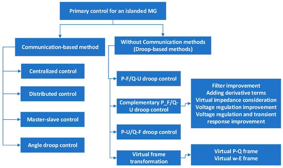
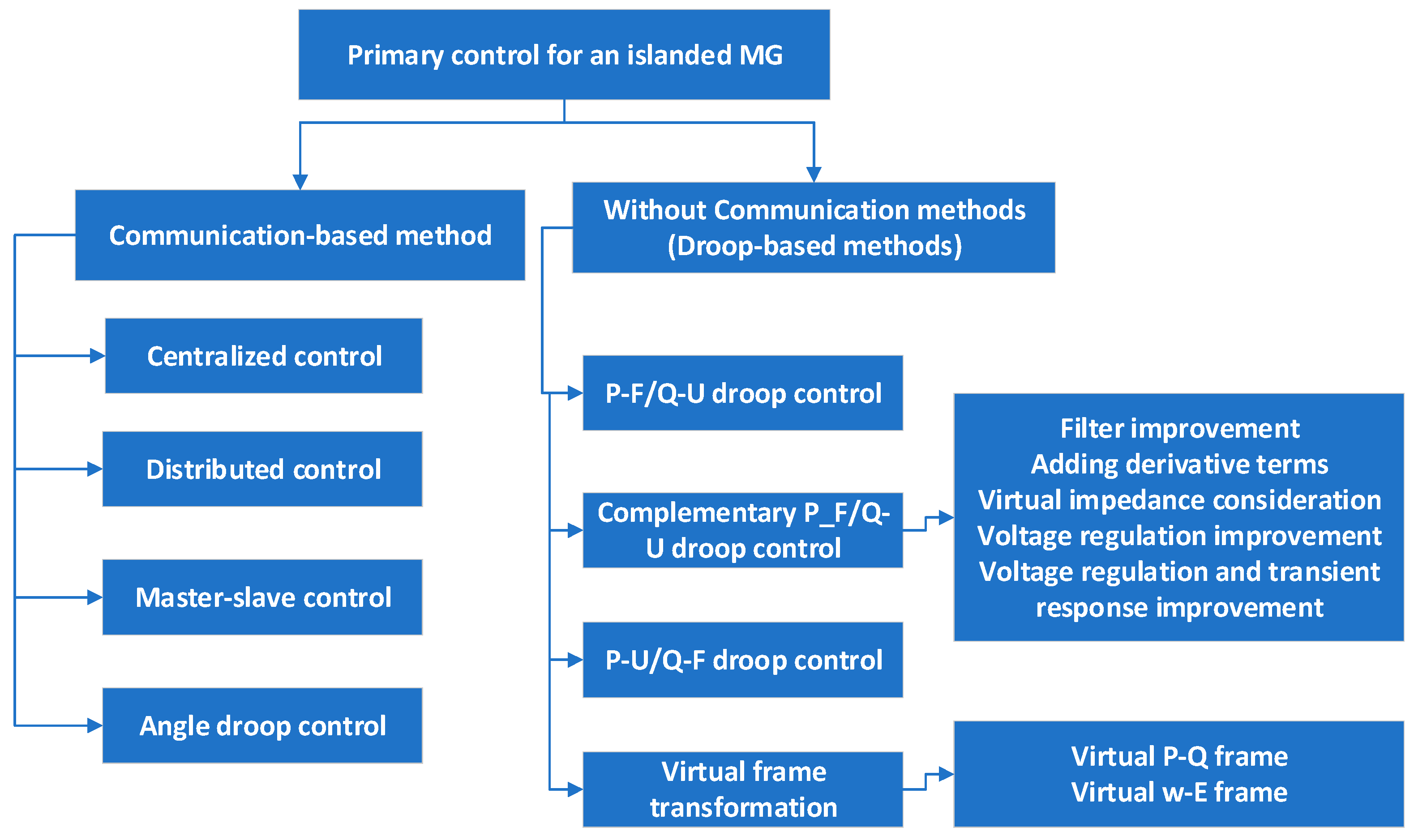
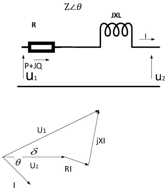
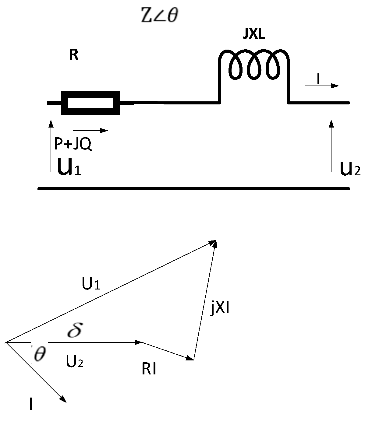
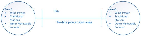
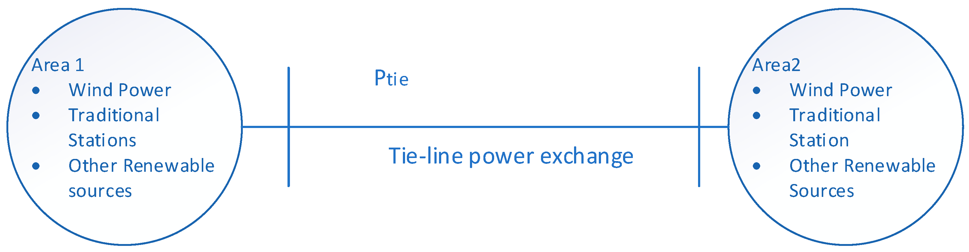

Disclaimer/Publisher’s Note: The statements, opinions and data contained in all publications are solely those of the individual author(s) and contributor(s) and not of MDPI and/or the editor(s). MDPI and/or the editor(s) disclaim responsibility for any injury to people or property resulting from any ideas, methods, instructions or products referred to in the content. |
© 2026 by the authors. Licensee MDPI, Basel, Switzerland. This article is an open access article distributed under the terms and conditions of the Creative Commons Attribution (CC BY) license.