


Abstract
Effective solar receiver design is pivotal to improving the efficiency of concentrated solar collectors, thereby advancing sustainable energy development. This study investigates the impact of receiver configuration on the thermal and exergy performance of parabolic trough collectors and proposes adopting a commercially available copper-finned tube as the receiver. Notably, thermal efficiency improved when the flat corrugated fin was redesigned into an arc-shaped thin-profile configuration. Specifically, the arc-shaped fin receiver outperformed its flat-fin counterpart, achieving thermal efficiencies of 75.8% and 68.5% at a mass flow rate of 0.1 kg/s, respectively. At a lower flow rate of 0.033 kg/s, peak water temperatures of 80 °C and 72 °C were recorded for the arc-shaped and flat-fin receivers, respectively. Comparative analysis further revealed that the arc-shaped fin yielded an average heat transfer coefficient 19–33.9% higher than that of the flat-fin receiver. Furthermore, at 0.033 kg/s, the arc-shaped fin demonstrated superior exergy efficiency, with peak and average values of 7.2% and 4.2%, respectively, compared with 5.2% and 3.0% for the flat-fin receiver. These findings highlight the potential of arc-shaped copper-finned tube receivers to optimize parabolic trough collector performance, offering a promising avenue for advancing sustainable energy development.
1. Introduction
According to published research, the parabolic trough collector (PTC) is a well-known solar thermal device for producing steam to generate power [1]. PTC is more effective than other concentrating solar systems due to its higher power generation capability [2,3]. The minimal area requirements, straightforward design, and use of less expensive materials result in lower greenhouse gas emissions than those of other concentrating solar systems [4,5]. Increased heat loss due to higher temperatures and poor heat transfer fluid (HTF) performance reduces the thermal efficiency of PTCs. Thermal approaches include modifying the receiver’s design, adding fins and turbulence-inducing components, and enhancing the HTF’s thermal conductivity using porous media and nanoparticles. Hu et al. [6] used top- and bottom-flattened receiver tubes and observed a 4.64% increase in thermal efficiency at higher PTC working temperatures. It is higher than 648 K, allowing the present receiver to operate at a higher temperature. Fattahi [7] showed that rectangular receivers outperformed triangular and trapezoidal receivers. A 45.4% increase in heat transfer was observed with fins, achieving a peak energy efficiency of 78.5% [8]. Liu et al. [9] investigated a receiver with inner and outer flow passages, where the water flowed through the inner tube that absorbed heat from the top receiver, and thermal oil flowed through the outer tube that absorbed solar radiation from the reflector. Motwani et al. [10] found that cutting the receiver’s top surface, where intense solar radiation is absent, reduces heat loss.
The receiver’s heat transfer area significantly improved convective heat transfer between the absorber and the HTF. Bellos et al. [11] enhanced the energy efficiency of a PTC by 1.27% with an internally finned receiver. Although it improved the receiver’s heat-transfer performance, the system’s pressure loss remained higher, requiring more pump power [12]. Vahidinia et al. [13] reported a maximum thermal efficiency enhancement of 0.27% using a finned receiver. When the input temperature was increased from 400 to 600 K, they observed a 3.1% decrease in the thermal efficiency and a 64.7% increase in the exergy efficiency. A central tube and two fins were used as the PTC receivers, with an efficiency of 48.57% [14]. Pazarlıoğlu et al. [15] found a 38% Nusselt number increment and a 16.82% entropy generation reduction by employing an elliptical-shaped dimpled receiver at an elliptical ratio of 1.66. The thermal efficiency increased from 57.7% to 59.05% when a double-loop evacuated receiver with a flat plate was used, as the flow rate increased from 0.017 kg/s to 0.033 kg/s [16]. Hamada et al. [17] experimentally investigated several receiver enhancement techniques and reported a 19.18% increase in thermal efficiency using a CuO/water nanofluid as the HTF. A higher enhancement of 37.76% was achieved by combining the CuO/water nanofluid with CuO nanoparticle-coated receiver tubes.
Chakraborty et al. [18] examined PTC’s straight and helical PTC receivers. The energy and exergy efficiencies increased by 10% and 5%, respectively, for the straight receiver. Akbarzadeh and Valipour [19] observed a 26–176% increment in the performance factor of a PTC when using a corrugated rather than a smooth receiver. The helical corrugated tubes outperformed the transverse-type corrugated receivers [20]. Akbarzadeh et al. [21] achieved a maximum thermal efficiency of 65.8% while increasing the friction factor from 35.5% to 84.8% by using a helical corrugated receiver. Babapour et al. [22] experimentally demonstrated that helically corrugated absorber tubes produced a substantially greater enhancement in the thermal performance of a PTC than Al2O3/water nanofluids. While increasing the Al2O3 nanoparticle concentration from 0.25 to 1.0 vol.% in a smooth absorber tube resulted in only a marginal improvement in the thermal performance factor, the corrugated absorber tube achieved a maximum thermal performance factor of 2.53, highlighting the greater effectiveness of receiver modification.
Optical losses are the primary cause of PTCs’ poor thermal performance [23]. Therefore, optical modification effectively enhanced PTC performance compared to thermal techniques. Cavity receivers improve PTC performance in the high-temperature zone on the cavity surface. Radiation escape from the receiver surface is lower in cavity-type receivers [24]. Loni et al. [25] achieved 77.26% efficiency using a cubic linear cavity receiver. Mohamad and Ferrer [26] observed a 7% higher efficiency with cavity-type receivers than with other cavity-type receivers when the temperature exceeded 873 K. An optimum cavity width of 50–70 mm was obtained using an arc-shaped linear cavity receiver [27]. As the aperture width increased, they observed increased heat loss and reduced optical loss. Vengadesan et al. [28] studied a semicircle-constructed parallel tube receiver with dual inlets. The heat transfer coefficient increased by 28.5% compared with that of a single absorber tube. Increasing the receiver length, width, and average irradiation significantly improves the PTC’s optical performance, thereby increasing the heat input to the receiver [29]. Bellos and Tzivanidis [30] highlighted the simultaneous use of optical and thermal strategies to enhance PTC performance. An internal radiation shield in the outer cover of the PTC reduced solar radiation loss beyond the receiver surface. The PTC efficiency with a radiation shield was 51.8%, 4.9% better than that of a standard receiver [31]. Excessive heat loss due to higher solar radiation was reduced by installing additional wing-like glass. Wang et al. [32] reduced heat loss by 24.2% using a radiation shield on an uncoated receiver. When the diameter of the coated radiation shield was increased from 57 to 97 mm, the decrease was 13.4% [33]. Qiu et al. [34] discovered a 5.04% efficiency improvement at maximum radiation and an optimum aerogel thickness of 20 mm.
Cross-section modification [35], adding fins [11], porous media [36], and turbulent generators [37] to the solar receiver improve convective and conductive heat transfer. Although nanofluids significantly improve PTC thermal performance, they are more expensive, and their increased viscosity requires greater pump power, thereby limiting their commercialization as HTFs in heat-exchange systems [38]. Optical-efficiency improvement approaches are more effective at increasing the thermal output. Thermal modification is a better technique for improving PTC performance at higher temperatures by significantly reducing the heat loss [23]. Combining optical and thermal improvement strategies can improve PTC performance to the next level [39]. The solar receiver was equipped with welded internal mild-steel fins that enhance heat transfer from the concentrated solar radiation, improving heat distribution across the receiver [40,41].
The comprehensive review of the existing literature indicates that significant efforts have been devoted to improving the thermal performance of PTCs through finned and cavity receivers, as well as other modified receiver geometries. While these approaches have demonstrated varying degrees of thermal enhancement, many require specialized receiver designs, complex manufacturing processes, or additional structural modifications, thereby limiting their practical implementation and increasing fabrication costs. Moreover, the potential of commercially available copper-finned receiver tubes as an efficient and economically viable alternative has not yet been systematically explored.
To the best of the authors’ knowledge, no previous study has experimentally investigated a commercially available copper-finned receiver tube modified into both flat and arc-shaped receiver configurations for PTC applications. The novelty of the proposed receiver lies not only in the use of a readily available commercial component but also in a simple arc-shaped geometric modification, achieved without complex fabrication or specialized manufacturing processes. Compared with conventional straight-finned receivers, the curved-fin profile increases the effective solar interception area while promoting partial cavity formation beneath the receiver. This geometric configuration enhances multiple reflections of the incident solar radiation, increases solar energy absorption, improves heat transfer to the working fluid, and suppresses thermal losses from the receiver surface. Consequently, the proposed design offers a practical and cost-effective approach for improving receiver performance while maintaining manufacturing simplicity and facilitating large-scale implementation.
Accordingly, the present work experimentally evaluates and compares the thermal and exergy performances of flat and arc-shaped copper-finned receiver configurations under outdoor operating conditions. The study establishes the influence of the proposed arc-shaped geometry on receiver thermal behavior and demonstrates its practical potential as a high-performance, commercially viable receiver configuration for parabolic trough solar collectors. The present study is discussed in five sections. Section 1 describes the background, purpose, and novelty of the current research. Section 2 describes the receiver specifications, experimental setup, and testing methodology. Section 3 presents the complete thermal performance measurement parameters and their numerical relationships. A discussion of the measured results and their uncertainties is presented in Section 4. Finally, Section 5 presents the major conclusions of this study.
2. Materials and Methods
2.1. Details of the Solar Receiver
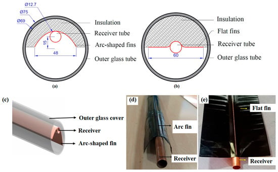
This experimental study investigated the thermal performance of a PTC with two receiver configurations: flat-finned and arc-shaped finned. Both receiver configurations were fabricated from the same commercially available copper-finned receiver tube, ensuring identical material properties and base dimensions, but differing only in their geometric configurations. It has a circular cross-section tube, 1.22 m long, welded to a thin, corrugated copper sheet by ultrasonic welding. The copper tube had a diameter of 12.7 mm and a thickness of 0.56 SWG, whereas the corrugated copper fin had a width of 120 mm and a thickness of 0.19 mm. A metal-binding wire was used to bend the copper fins into an arc shape with a width of 48 mm. To create a heated hollow zone beneath the receiver, the receiver was eccentrically placed 15 mm from the center of the outer glass cover. The arc-shaped cavity was 15 mm deep from the receiver. A transparent evacuated glass tube is used to prevent heat loss. It has inner and outer diameters of 69 and 75 mm, respectively. The top heat loss from the receiver considerably reduces performance [23]. Therefore, the top of the receiver is covered with 20 mm-thick glass wool insulation to prevent heat loss.
Compared with the flat-finned receiver, the arc-shaped finned receiver features a modified fin geometry that alters several characteristics governing the receiver’s optical and thermal behavior. The curved fin profile increases the effective surface area exposed to concentrated solar radiation while partially enclosing the region beneath the receiver, forming a semi-cavity geometry. Consequently, the modified receiver geometry is expected to influence the effective interception and utilization of the concentrated solar radiation, the radiative energy exchange within the receiver region, the overall heat-loss characteristics, and the transfer of thermal energy from the receiver to the working fluid. Therefore, the thermal and exergy performance of the arc-shaped receiver should be interpreted as the combined effect of these geometric modifications rather than any individual geometric feature. The dimensional details of the proposed system are presented in Table 1. Figure 1 depicts a two-dimensional cross-sectional view of a straight, arc-shaped receiver, along with realistic three-dimensional images.
Table 1.
Specifications of the selected PTC.
Figure 1.
A two-dimensional schematic view of the receiver’s cross-section: (a) Arc-shaped fins; (b) Flat fins. Three-dimensional and actual views of receiver tubes: (c) Three-dimensional view of arc-shaped fins; (d) Arc-shaped fins; (e) Flat fins.
2.2. Experimental Setup
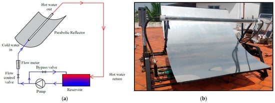
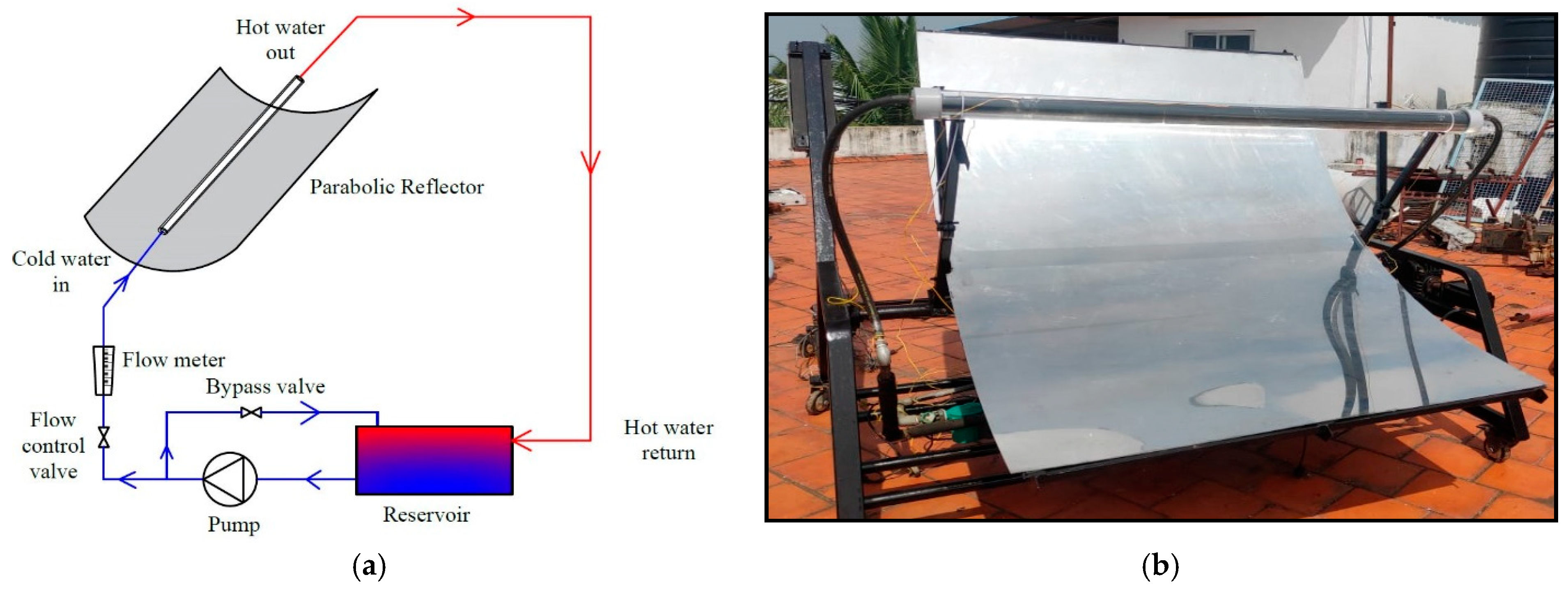
The current system employs a parabolic reflector to focus solar radiation onto its focal line. A stainless-steel parabolic reflector with mirror film measures 1.22 m wide by 1.7 m long and has an aperture area of 2.07 m2. With a focal distance of 0.6 m, the copper receiver is positioned along the reflector’s focal line and covered with clear, evacuated glass. Water was used as the HTF, circulated by a hot-water pump. The hot water was stored in a 45 L tank and then circulated back to the inlet section. A 50 mm layer of glass wool insulated the storage tank, with a 3 mm thick stainless-steel sheet. The insulation for the piping was 25 mm thick. Figure 2 depicts the PTC schematic and the current experimental setup.
Figure 2.
The PTC experimental test setup: (a) Schematic layout; (b) Actual view.
2.3. Instruments and Measurement
The experiment was conducted externally under radiation recorded from March to April 2023. The experiments were conducted at a site near Chennai, Tamil Nadu, India (12°49′25″ N, 80°02′40″ E), which has a tropical humid climate with high solar availability throughout most of the year. The site typically experiences approximately 7 h of bright sunshine per day and receives an annual average global solar radiation of about 5.5 kWh m−2 day−1, with clear-sky global solar irradiance approaching 1000 W m−2 around solar noon. These favorable climatic conditions make the location well suited for experimental investigations of PTCs. During the experiment, meteorological conditions, such as solar radiation, ambient temperature, and wind velocity, were measured. Water was selected as the heat transfer fluid because the primary objective of this study was to experimentally compare the thermal and exergy performance of the flat-finned and arc-shaped receiver configurations under identical operating conditions. Water is a widely used reference heat-transfer fluid for experimental investigations of parabolic trough collectors owing to its favorable thermophysical properties, low cost, and environmental compatibility. Furthermore, the experiments were conducted under the climatic conditions of Chennai, India, where freeze protection is not required. Although propylene glycol/water mixtures are commonly employed in year-round solar thermal systems operating in cold climates, their evaluation was beyond the scope of the present investigation. A rotameter measures the flow rate, and the pressure drop is calculated using a U-tube manometer. The radiation intensity and wind velocity were measured at regular intervals using a pyranometer (AT Delta-T Model) and an anemometer (WS-GP2 Model). Resistance temperature detector sensors (PT-100) were used to measure temperature. A U-tube manometer was used to monitor the pressure drop. Table 2 lists the measurement instrument uncertainties.
Table 2.
Instrumentation details.
2.4. Experimental Procedure
The present investigation has two receiver classifications: copper tubes with flat corrugated fins and copper tubes with arc-shaped corrugated fins with top-side insulation. Temperature sensors were installed before and after the outlet sections to measure temperature. Tap water is used as HTF and supplied at five flow rates (0.033 kg/s, 0.05 kg/s, 0.067 kg/s, 0.083 kg/s, and 0.1 kg/s). A hot-water circulation pump delivered water at 27 °C, and the water storage tank was drained daily after the test and refilled before the experiment. The experiment was conducted in an open environment with comparable weather conditions in a three-story building [42]. Each experimental test was conducted between 10:00 and 15:00 h under outdoor conditions. This period was selected because it provides relatively high and stable beam solar radiation, thereby minimizing the influence of low solar altitude and rapidly varying irradiance during the morning and late afternoon. The parabolic trough collector was installed with its aperture facing south and aligned north–south. Manual solar tracking was performed throughout the experimental period to maintain the receiver along the reflector focal line and maximize the interception of direct solar radiation.
The temperatures of the water, glass cover, and receiver were measured with PT-100 temperature sensors and recorded with a data logger and a computer. The receiver surface temperature and outer glass cover temperature were measured using PT-100 temperature sensors installed at three equally spaced locations along the length of the receiver and the outer glass cover, respectively. The sensors were attached using a high-temperature thermally conductive adhesive to ensure good thermal contact with the measurement surfaces, while the sensor leads were thermally insulated to minimize the influence of the surrounding environment on the temperature measurements. The temperatures recorded at the three locations were averaged and used in the subsequent thermal performance analysis to account for possible temperature non-uniformity and improve the reliability of the experimental measurements.
The current receiver acted differently, based on the available solar radiation intensity throughout the test. When a cloudy state was observed, the outlet temperature dropped abruptly and increased again when a clear sky was observed. Despite clear sky radiation, sudden increases and decreases in radiation intensity affect the outlet water and receiver temperatures. To ensure a reliable comparison, the experiments were conducted repeatedly for each investigated mass flow rate under closely matched outdoor environmental conditions. All performance parameters were calculated from measurements recorded at 5 min intervals and subsequently averaged over 30 min intervals to minimize the influence of short-term environmental fluctuations. The average beam solar radiation, ambient temperature, and wind speed for both receiver configurations differed by less than approximately 1–1.5%, confirming comparable testing conditions. The PTC performance was tested using two distinct receiver configurations at the selected flow rates. An experimental test was conducted over three cycles, with flow rates continuously monitored for 5 days. The observations were selected from multiple days of monitoring based on average beam radiation and ambient temperature.
3. Performance Analysis
The performance analysis is conducted under the following assumptions.
- The current system is in a steady state.
- Water properties at the mean temperature were measured.
- The outer cover is completely vacuumed.
- Heat loss at the collector’s side edges was ignored.
- The effect of outer cover thickness was not considered.
- The current flow is fully developed owing to the greater receiver length.
3.1. Energy Analysis
The energy balance of the heating process is given by Equation (1).
Here, Qw,in, Qs,in, Qw,out, and Qloss are the water intake energy, solar energy received by the reflector, water outlet energy, and heat loss from the system (W), respectively.
where , Cp, To, and Ti are the mass flow rate (kg/s), specific heat capacity (J/kgK), output temperature (°C), and water inlet temperature (°C), respectively.
The solar energy received by the PTC was computed using Equation (3).
Aa and Gb are the aperture area (m2) and solar radiation (W/m2), respectively.
The aperture area of the PTC:
W and L are the width (m) and length (m), respectively.
Heat loss is caused by radiative heat transfer, which depends on the receiver’s emissivity. Both radiative and convective heat loss contribute to the total heat loss, as given by Equation (5).
Qloss,conv and Qloss,rad are the convective heat loss (W) and radiative heat loss (W) from the receiver.
The difference between the cover and the ambient temperature causes convective heat loss.
Here, Aco is the outer surface area of the glass cover (m2), ha is the convective heat transfer coefficient between the outer glass cover and the ambient air (W/m2K), and Tc and Ta are the outer glass cover and ambient temperatures (°C), respectively.
Dh, P, and Ac are the outer glass cover’s hydraulic diameter (m), perimeter (m), and cross-sectional area (m2).
The wind heat loss coefficient was estimated from ambient air velocity [43].
Vwind and Dco represent the wind speed (m/s) and the glass cover’s diameter (m), respectively.
Heat loss due to radiation:
Tc and Tsky are the temperatures (°C) of the outer cover and sky, respectively.
The sky temperature [44]:
Heat transfer coefficient (h):
Tr and Tfm are the average temperatures of the receiver and water (°C). It is noted that the heat transfer coefficient calculated in the present study represents an effective heat transfer coefficient derived from the experimentally measured useful heat gain.
The Nusselt number (Nu) quantifies convective heat transfer in terms of the total heat absorbed by the water.
Dri and k are the receiver’s internal diameter (m) and the thermal conductivity of water (W/mK). The receiver temperature used in the calculation was obtained by averaging the temperatures measured at three equally distributed locations along the receiver. Accordingly, the calculated heat transfer coefficient and Nusselt number represent effective average values for the entire receiver rather than local values.
The thermal efficiency was evaluated based on the total beam solar radiation incident on the collector aperture area. Accordingly, the input solar energy was calculated as the product of the measured beam solar radiation intensity and the collector aperture area, without accounting for optical losses.
Thermal efficiency (ƞth):
3.2. Exergy Analysis
The inlet exergy of water (Ėxw,in) is also known as the useful exergy of water [45].
The inlet exergy of water,
The outlet exergy of water (Ėxw,out),
The useful exergy (Ėxu),
The Petela model [46] was originally developed for a hemispherical radiation source. For concentrating solar collectors, Badescu [47] proposed a correction factor to account for the optical concentration effect. The available exergy (Ėxs) is calculated using Equation (18).
Tsun—Sun temperature (5770 K).
Here, fH is the radiation source geometric factor, the ratio of the concentration ratio of the current PTC (CR), and the maximum solar radiation concentration (Cmax) at Earth orbit (≈46,200). The current PTC’s concentration ratio was calculated by dividing the aperture area by the receiver area.
The exergy efficiency (ƞex):
4. Results
4.1. Stagnation Test (No-Load Test)
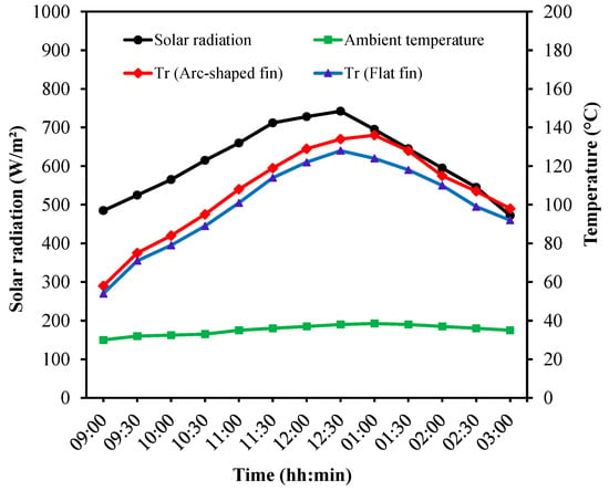
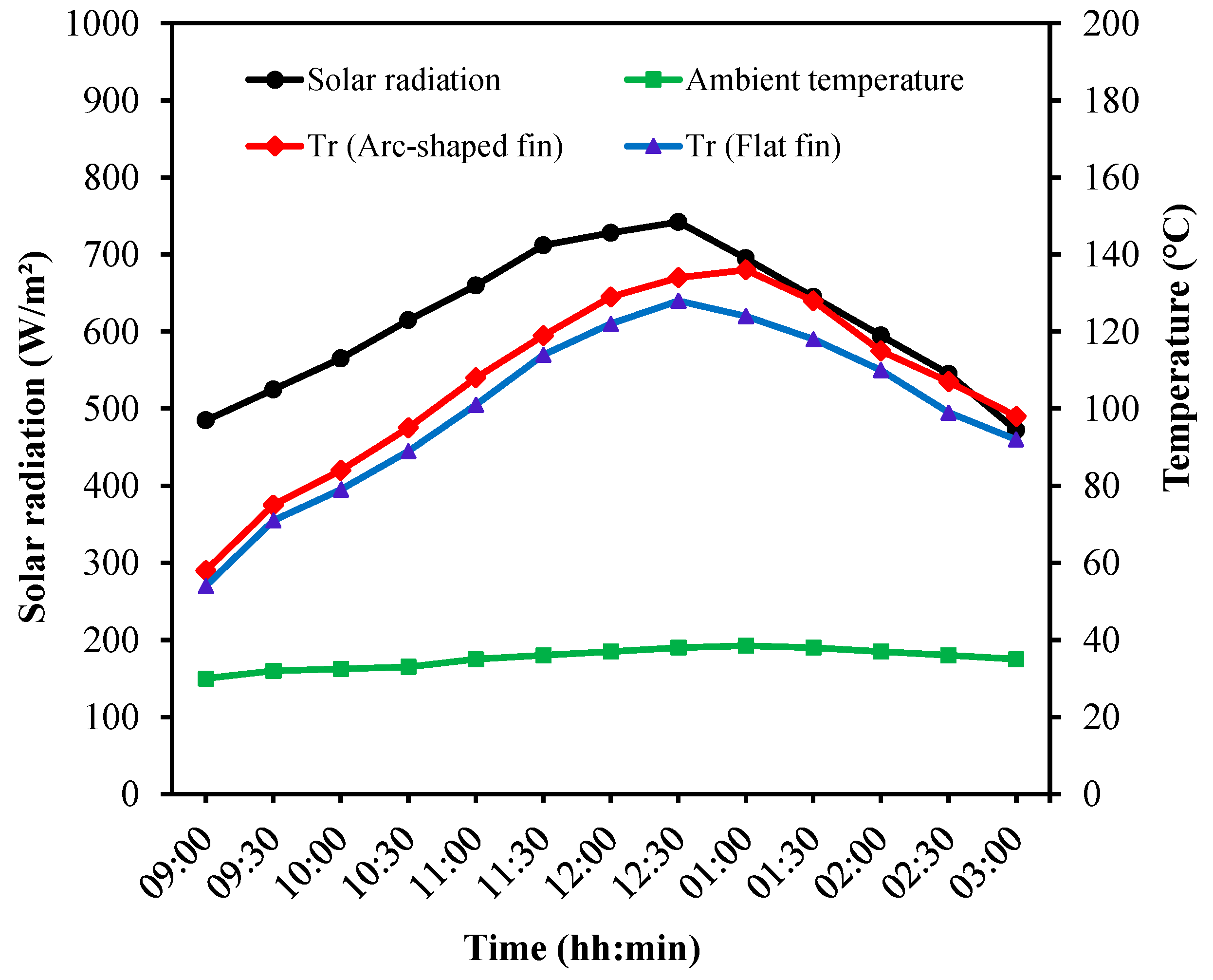
This study explored the performance of a PTC employing a commercially available copper-finned tube as the receiver. It is a smaller-diameter copper tube with corrugated copper fins to maximize heat absorption from incident solar radiation. Corrugated fins were further modified by bending them into arc shapes. Both receivers have top-surface insulation to prevent heat loss. The arc-shaped fins allow the receiver to capture more heat from available solar radiation by reflecting radiation that would otherwise escape the receiver’s focal line. Therefore, the modified arc-shaped fins increased heat absorption by acting as fins and secondary reflectors. A receiver with flat, corrugated fins can only increase heat absorption by increasing the surface area. This resulted in a higher water temperature when an arc-shaped finned receiver was used. Figure 3 shows the results of the stagnation condition experiment.
Figure 3.
Stagnation temperature measurement.
A stagnation test was first performed to determine the maximum temperature reached by both receivers in the absence of any HTF, with an average radiation of 614 W/m2 and an ambient temperature of 35 °C. A peak receiver temperature of 134 °C was observed when an arc-shaped corrugated finned receiver was used. The highest receiver temperature with flat corrugated fins was 128 °C, lower than that of the modified finned receiver, indicating that a higher temperature was reached when the flat fin changed to an arc-shaped fin. The flat-finned receiver absorbed more heat from the concentrated radiation but did not reflect radiation to the receiver. Therefore, the temperature difference measured by the receivers was 4–8 °C. Owing to the higher solar radiation concentration, the maximum receiver heat flux is higher for the arc-shaped finned receiver than for the flat-finned receiver.
4.2. Water Heating Test (Load Test)
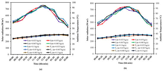
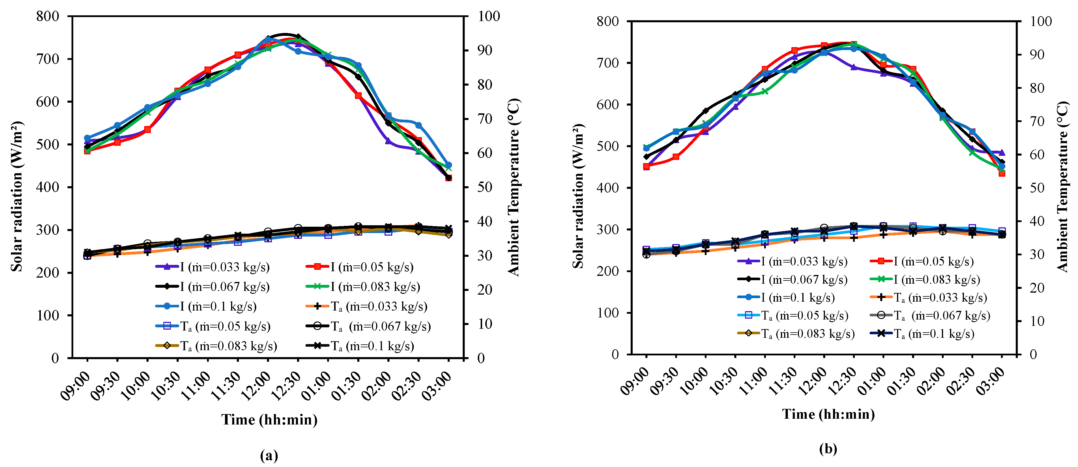
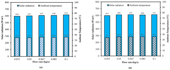
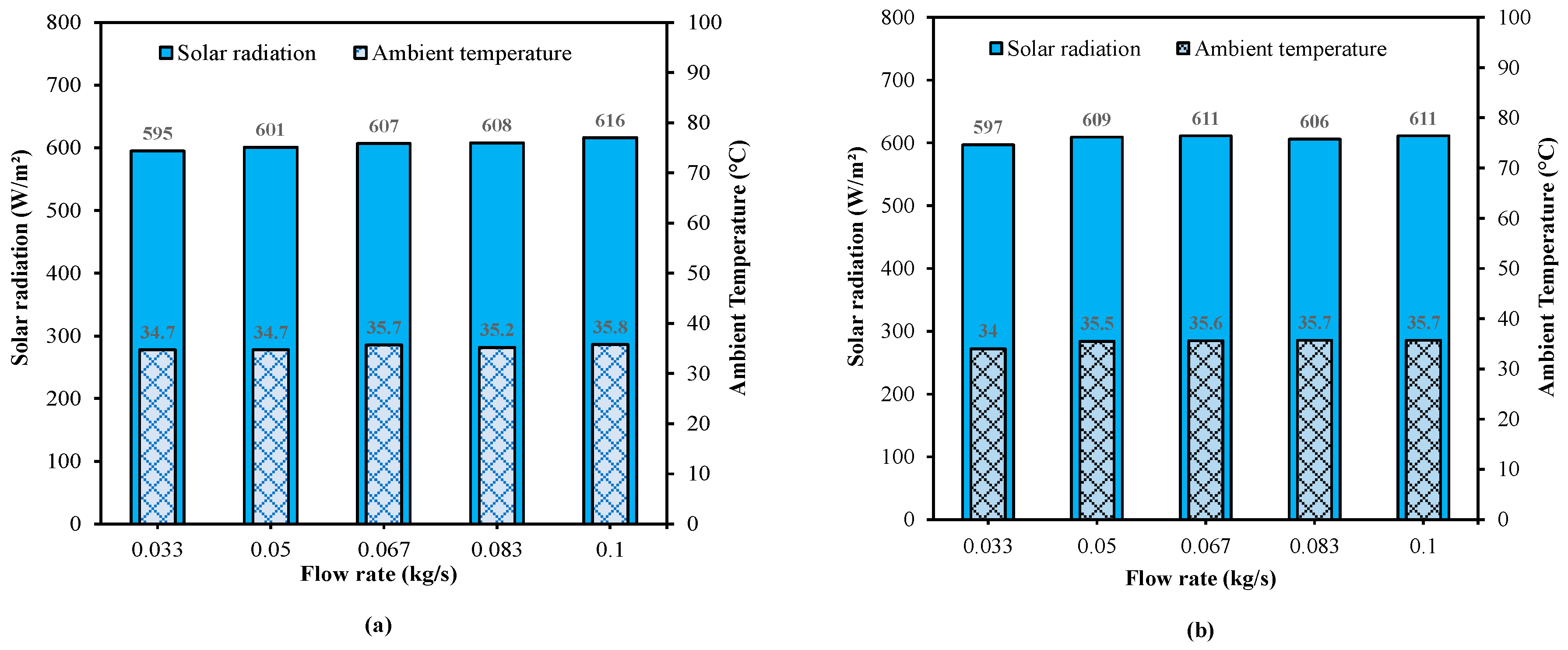
The thermal performance of the receiver was evaluated experimentally under identical environmental conditions. Wind velocity, ambient temperature, and radiation intensity significantly influence water temperature. Therefore, the average value of these factors was used to identify environments with similar conditions. A performance analysis was conducted, and two receivers with different fin shapes were tested, with their performance compared at various water flows. The data obtained under similar environmental conditions were used to compare the two distinct receiver configurations. The solar radiation showed an upward trend, reaching 422 W/m2 and 752 W/m2. Similarly, 34 °C and 38.8 °C were the lower and peak ambient temperatures. The average solar radiation during the test of the arc-shaped receiver is 595 W/m2, 601 W/m2, 607 W/m2, 608 W/m2, and 615 W/m2 for the flow of 0.033 kg/s, 0.05 kg/s, 0.067 kg/s, 0.083 kg/s, and 0.1 kg/s, respectively. The average ambient temperatures on the same testing days were 34.7 °C, 34.7 °C, 35.7 °C, 35.2 °C, and 35.8 °C, respectively. The corresponding average ambient temperatures were 34 °C, 35.5 °C, 35.6 °C, 35.7 °C, and 35.7 °C. Figure 4 shows the variation in ambient temperature and solar radiation. Similar weather conditions were observed during the test period (Figure 5). Table 3 compares the average environmental conditions for the arc-shaped and flat-finned receiver tests at each mass flow rate. The average solar radiation, ambient temperature, and wind speed were closely matched, with percentage differences below 1% for solar radiation and ambient temperature and approximately 1.3% for wind speed. These small deviations confirm that the performance differences primarily resulted from the receiver geometry rather than variations in the outdoor testing conditions.
Figure 4.
Variation in solar radiation and ambient temperature during the experimental evaluation: (a) Arc-shape receiver; (b) Flat receiver.
Figure 5.
Average solar radiation and ambient temperature: (a) Arc-shape receiver; (b) Flat receiver.
Table 3.
Quantitative comparison of environmental conditions.
4.3. Temperature Measurements
The temperature measurements were recorded at regular intervals using a temperature sensor. The circulation pump constantly recirculates water. The parabolic reflector’s focused sunlight raised the water temperature in the receiver. The temperature of the water storage tank increased considerably after cycling. Accordingly, the water inlet temperature began to increase, raising the water temperature at the receiver output. The receiver temperature rose due to radiation and peaked at midday. Thus, the incoming water absorbed more heat, and the outlet water temperature increased.
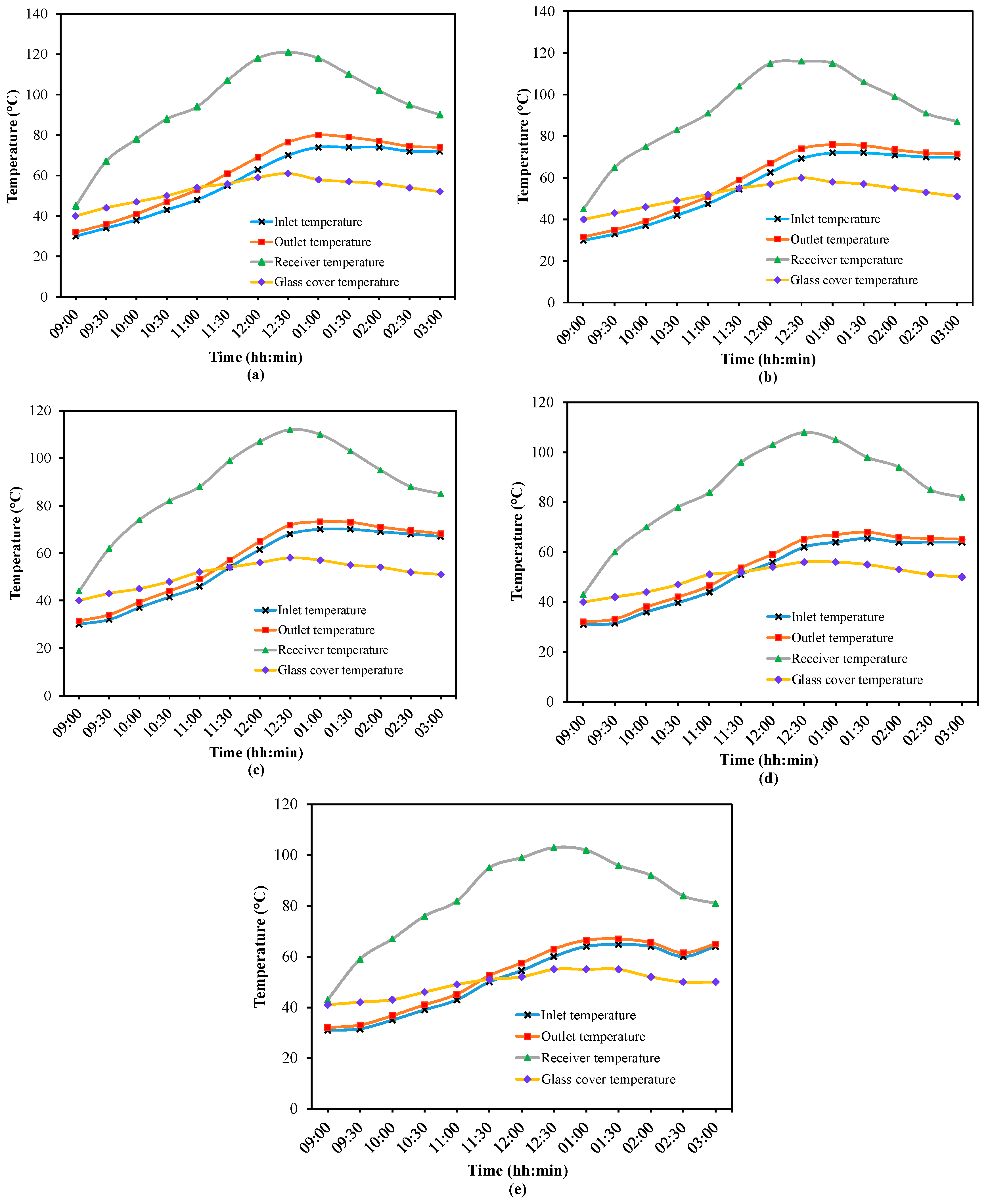
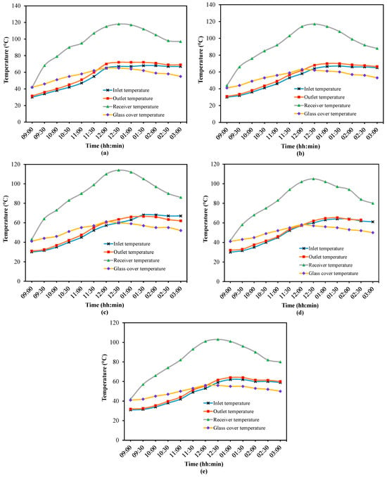
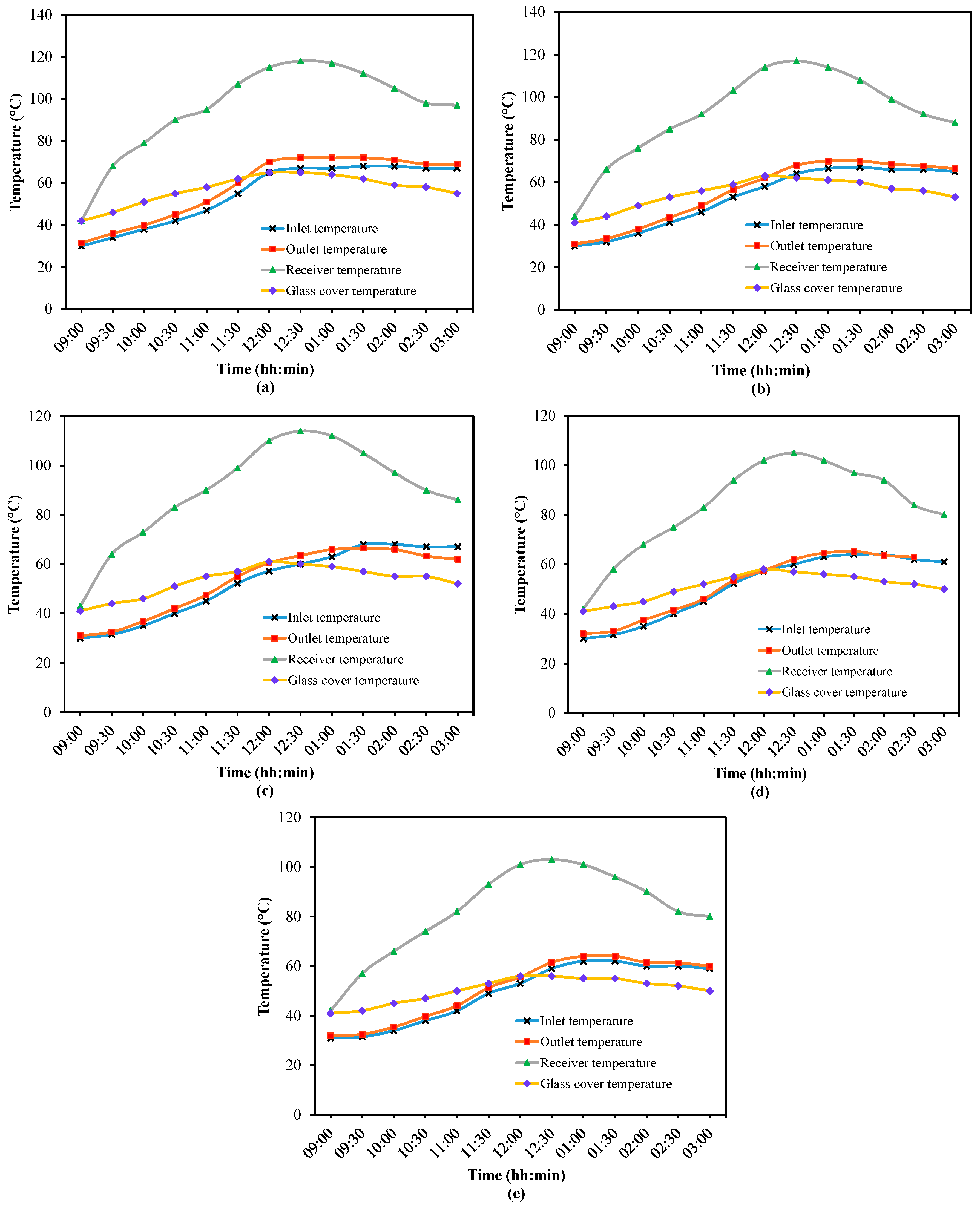
The average inlet water temperature was 57.5 °C, 56 °C, 55 °C, 52 °C, and 51 °C at flow rates of 0.033 kg/s, 0.05 kg/s, 0.067 kg/s, 0.083 kg/s, and 0.1 kg/s, respectively, during the investigation of arc-shaped finned receiver. For similar flow rates, the maximum water temperatures were 80 °C, 76 °C, 73 °C, 68 °C, and 67 °C, respectively. The average water temperatures of the corresponding testing days were 61.5 °C, 59 °C, 57.5 °C, 54 °C, and 53 °C when the modified finned receiver was used. The receiver with flat corrugated fins reached maximum water temperatures of 72 °C, 70 °C, 66.5 °C, 65 °C, and 64 °C at 0.033 kg/s, 0.05 kg/s, 0.067 kg/s, 0.083 kg/s, and 0.1 kg/s, respectively. The average outlet temperatures were 58.3 °C, 55.7 °C, 53.3 °C, 52.4 °C, and 51 °C. The inlet water temperature decreased from 55 °C to 49 °C as water flow increased. Based on the observations, the maximum water temperature was reached at a lower flow rate for both receiver configurations. Furthermore, the increase in water temperature decreased as flow rates increased. This was caused by the higher volume of water flowing at a higher flow rate. When the flow rate was increased to 0.1 kg/s, the peak temperature difference, measured at 6.5 °C, decreased to 3 °C. The same is true for the flat-finned receiver: 5 °C and 2.6 °C at higher flow rates.
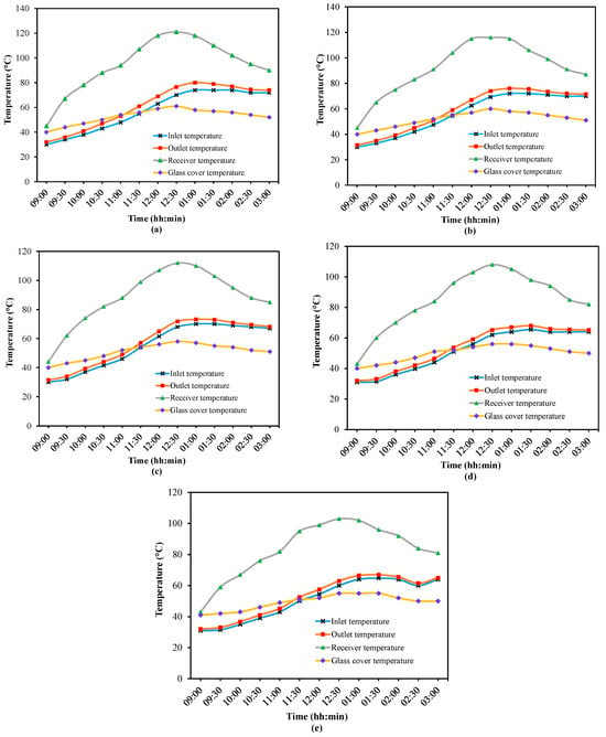
The peak receiver temperature was measured by using a modified fin shape during the stagnation test. The peak receiver temperature was lower with a flat-fin receiver. This was due to multiple reflections of solar radiation from the arc-shaped fin. The maximum receiver temperature was recorded at a flow rate of 0.033 kg/s, corresponding to 121 °C. The increased water flow rate reduces the receiver temperature by increasing the receiver’s useful heat absorption. Maximum receiver temperatures of 116 °C, 112 °C, 108 °C, and 103 °C were measured when the flow was increased to 0.05 kg/s, 0.067 kg/s, 0.083 kg/s, and 0.1 kg/s, respectively. The range is 118–103 °C for the flat-finned receivers. Average temperature ranges of 95–83 °C and 96–82 °C were observed for arc-shaped and flat-finned receivers, respectively. The higher the receiver’s temperature, the higher the heat absorption. The outer cover temperature ranged from 65 °C to 61 °C and from 61 °C to 59 °C during testing of a flat and an arc-shaped finned receiver. The higher the glass temperature, the greater the heat loss when a flat-finned receiver is used. Figure 6 and Figure 7 show the temperature measurements performed during the experimental test of the PTC using flat and arc-shaped corrugated finned receivers.
Figure 6.
Temperature measurements for arc-shaped fins: (a) ṁ = 0.033 kg/s; (b) ṁ = 0.05 kg/s; (c) ṁ = 0.067 kg/s; (d) ṁ = 0.083 kg/s; (e) ṁ = 0.1 kg/s.
Figure 7.
Temperature measurements for flat fins: (a) ṁ = 0.033 kg/s; (b) ṁ = 0.05 kg/s; (c) ṁ = 0.067 kg/s; (d) ṁ = 0.083 kg/s; (e) ṁ = 0.1 kg/s.
The outlet water temperatures achieved in the present study are suitable for low-temperature solar thermal applications, including domestic hot water production, swimming pool heating, solar-assisted drying, and low-temperature space heating systems such as radiant floor heating. These operating temperatures are also appropriate for preheating applications and district heating return lines. However, conventional high-temperature space heating systems generally require higher operating temperatures than those investigated in the present study. When arc-shaped corrugated fins were used, the PTC’s water temperature remained higher. As the mass flow rate increased, the working fluid extracted heat from the receiver more rapidly, thereby increasing the useful heat gain while simultaneously reducing the receiver surface temperature. Since the glass cover receives heat mainly through radiation and natural convection from the hot receiver, the reduction in receiver temperature decreased the heat transferred to the glass cover. Consequently, the glass cover temperature decreased as the mass flow rate increased. Thus, the observed reduction in glass cover temperature is an indirect consequence of enhanced heat removal by the working fluid rather than a direct effect of the flow rate itself.
4.4. Useful Heat
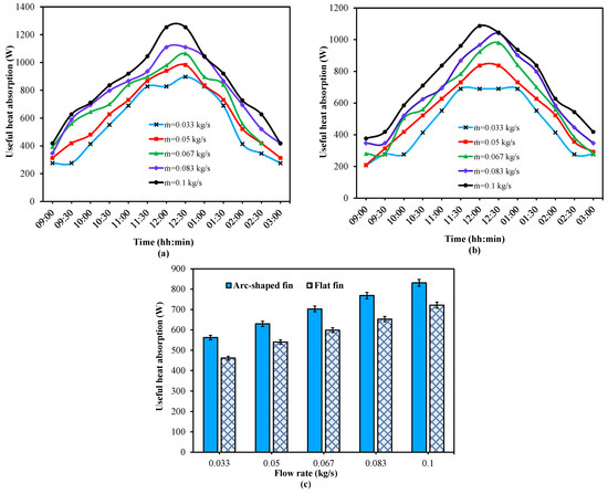
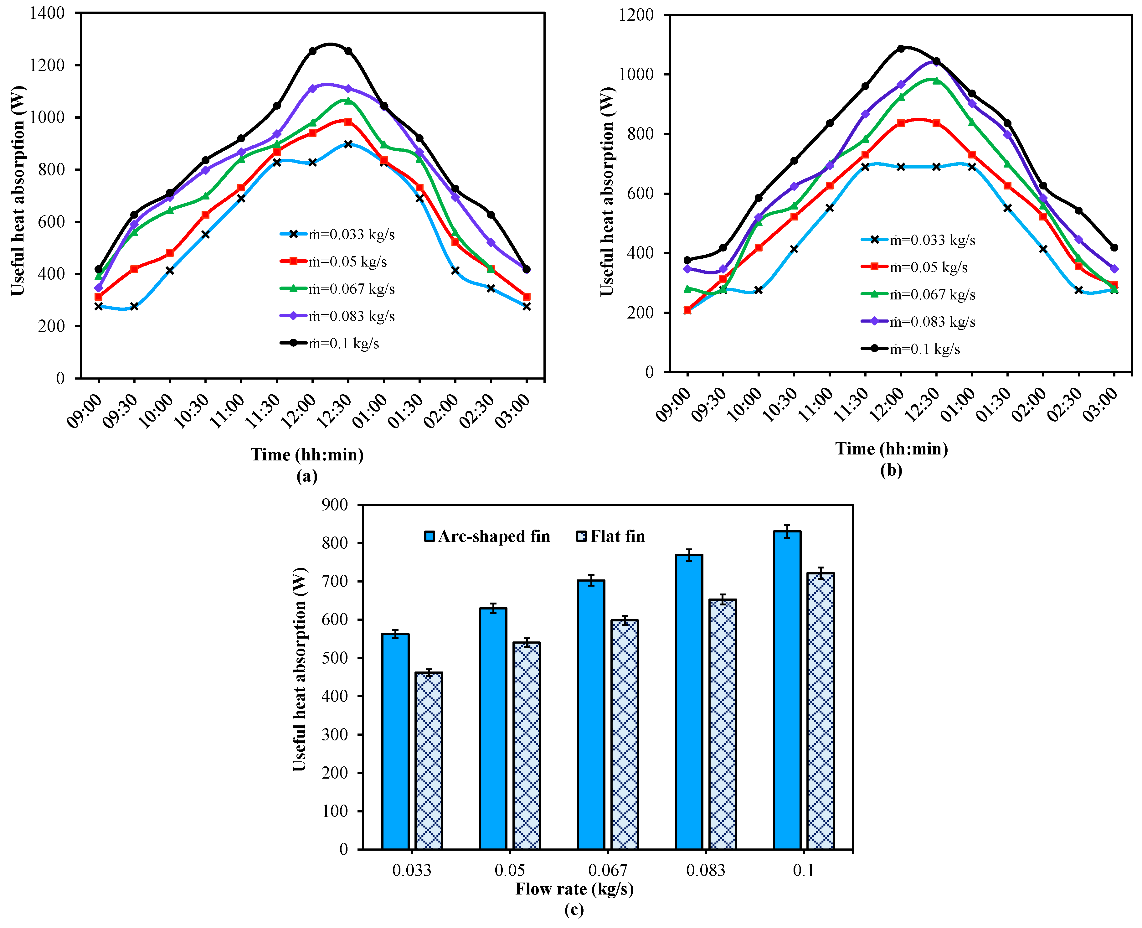
The sensible heat equation was used to compute the water’s useful heat absorption. Due to the higher receiver temperature and effective heat exchange with water, the maximum heat absorption of water is higher for the arc-shaped finned receiver at all flow rates. The average heat gain for the modified finned receiver is 562 W, 629 W, 702 W, 769 W, and 831 W at 0.033 kg/s, 0.05 kg/s, 0.067 kg/s, 0.083 kg/s, and 0.1 kg/s, respectively. The values for the flat-finned receiver are 462 W, 540 W, 598 W, 653 W, and 722 W, which are 21.6%, 16.5%, 17.4%, 17.8%, and 15% lower than those of the modified finned receiver. The increased receiver hot-surface area and continuous reflections of focused solar radiation by the arc fins resulted in greater useful heat gain in the water, driven by higher receiver temperatures. It increases with increasing flow rate, irrespective of the receiver type. A smaller temperature difference was observed at higher flow rates due to the greater water mass. Figure 8 depicts the differences between the useful heat gain for the current receiver configuration and the average useful heat absorption.
Figure 8.
Useful heat absorption by the receiver: (a) Arc-shaped fins; (b) Flat fins; (c) Average useful heat absorption by the solar receivers.
4.5. Heat Transfer Coefficient
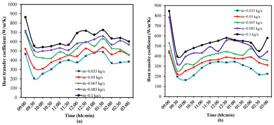
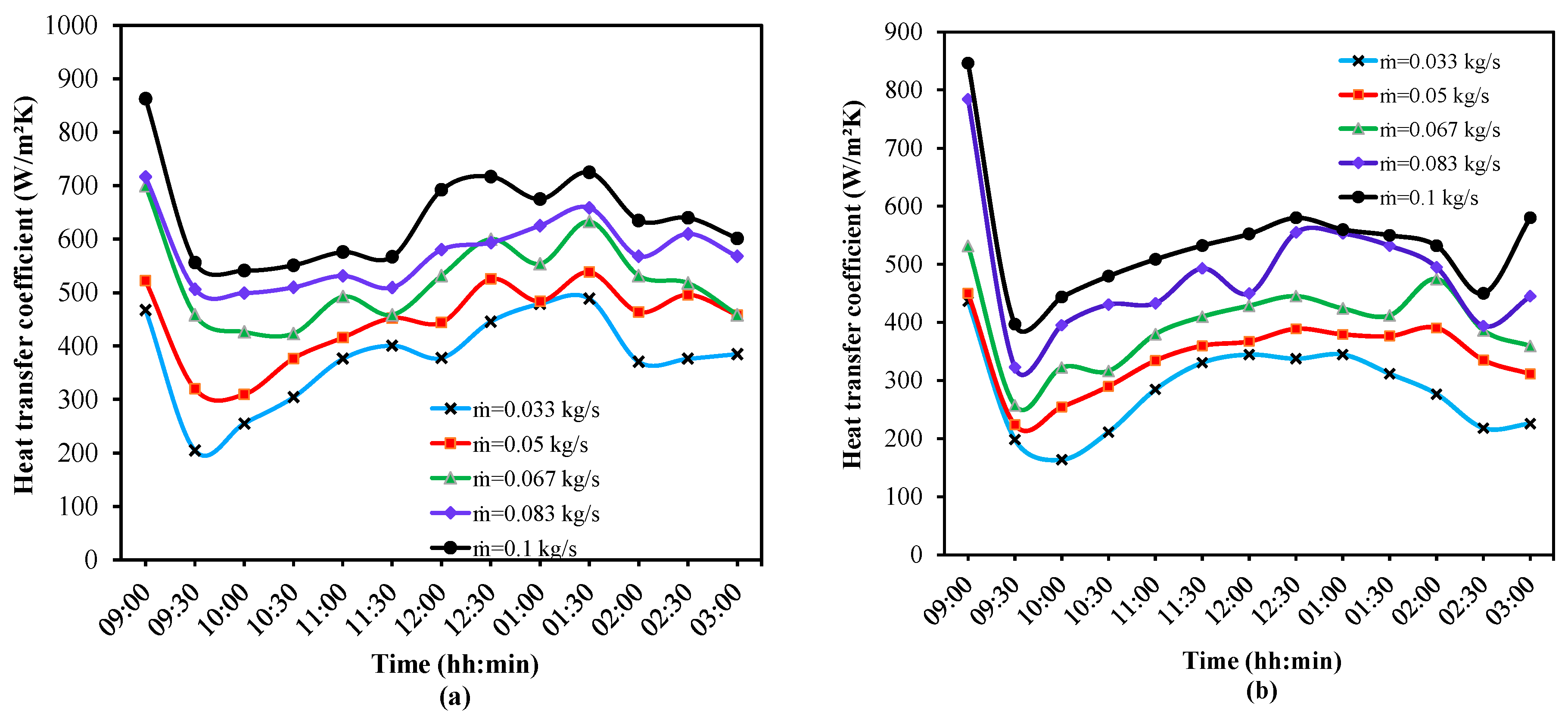
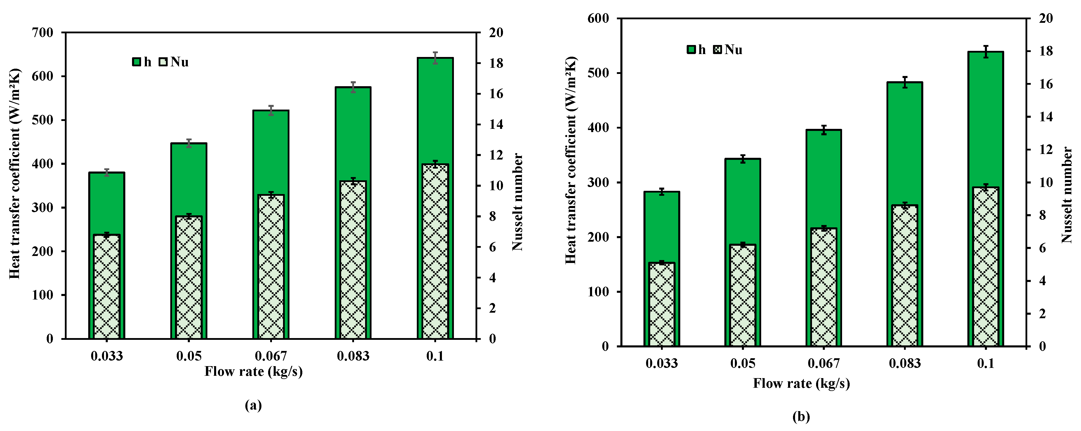
The heat transfer coefficient (h) represents the overall heat-transfer capability of the receiver and is derived from experimentally measured useful heat gain. Since the receiver incorporates externally attached copper fins exposed to concentrated solar radiation, the calculated coefficient reflects the combined effects of solar energy absorption, heat conduction through the fins and tube wall, and convective heat transfer to the working fluid. If the receiver surface temperature is higher, more heat is exchanged with water due to a larger temperature difference. The current receiver is a copper-finned tube with a larger surface area, which receives more radiation. Furthermore, the present receiver has a smaller diameter, resulting in a higher concentration ratio and higher solar energy intensity. An additional fin increases heat and solar radiation absorption, as well as the receiver surface temperature. Finally, it receives more heat, and water’s heat absorption increases. The value of h for an arc-shaped finned receiver is always higher than that for a flat-finned receiver. The average value of h is 376 W/m2K, 446 W/m2K, 522 W/m2K, 575 W/m2K, and 642 W/m2K, respectively at 0.033 kg/s, 0.05 kg/s, 0.067 kg/s, 0.083 kg/s, and 0.1 kg/s. They were 283 W/m2K, 343 W/m2K, 396 W/m2K, 483 W/m2K, and 539 W/m2K, respectively, for flat corrugated finned receivers. Owing to the higher useful heat absorption by water, the average h for the arc-shaped finned receiver was 33.9%, 30%, 31.8%, 19%, and 19% higher than that for the flat-finned receiver.
Compared with the flat-finned receiver, the arc-shaped fin geometry is expected to improve the effective utilization of the concentrated solar radiation by partially enclosing the region beneath the receiver, thereby forming a semi-cavity configuration. From a radiation heat transfer perspective, this geometry is likely to increase the likelihood of multiple reflections before the reflected rays escape into the surroundings, thereby reducing radiative losses and increasing the fraction of intercepted solar energy available for heat transfer. Consequently, the receiver attains a higher surface temperature and transfers more thermal energy to the working fluid as useful heat. In contrast, although the flat fins increase the effective heat-transfer area, they do not create a semi-cavity beneath the receiver and therefore offer comparatively less potential to retain the intercepted solar energy. At 0.033 kg/s, 0.05 kg/s, 0.067 kg/s, 0.083 kg/s, and 0.1 kg/s, the modified finned receiver could achieve maximum h of 488 W/m2K, 538 W/m2K, 633 W/m2K, 659 W/m2K, and 725 W/m2K. The flat-finned receiver peaked at 344–580 W/m2K at 0.033–0.1 kg/s. It was found that increasing the flow rate improved useful heat absorption and increased the heat transfer coefficient (Figure 9).
Figure 9.
Heat transfer coefficient: (a) Arc-shaped fins; (b) Flat fins.
Although the heat transfer coefficient is presented as a function of the heat-transfer fluid flow rate, its calculation inherently accounts for the influence of incident solar radiation. The useful heat gain and receiver surface temperature used in the calculation were experimentally measured under the prevailing outdoor solar radiation conditions. Therefore, the reported heat transfer coefficients represent the combined effects of solar irradiance, receiver temperature, and fluid flow rate rather than the influence of flow rate alone. To ensure a meaningful comparison between the two receiver configurations, the experiments were performed under closely matched solar radiation and ambient conditions, as discussed in Section 4.2.
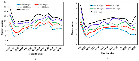
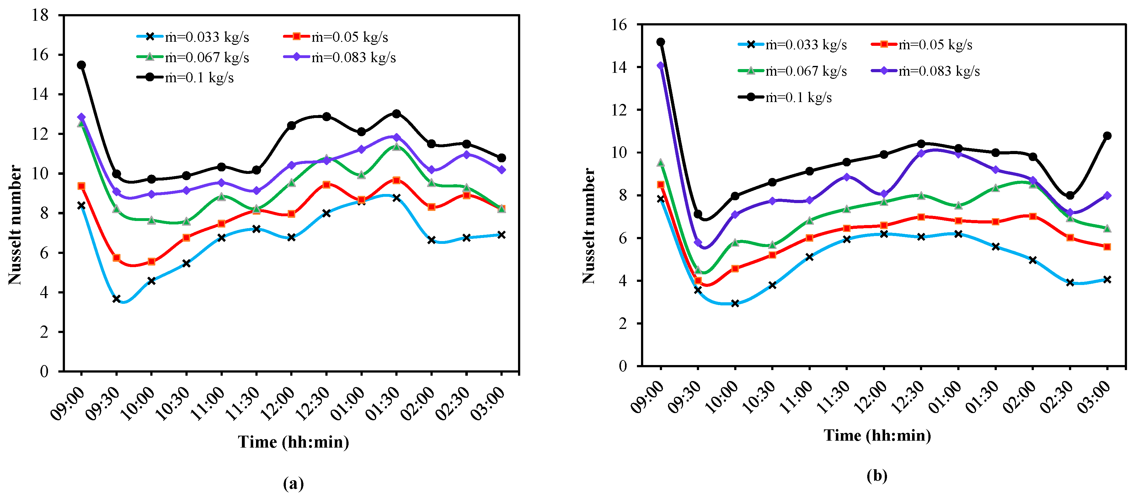
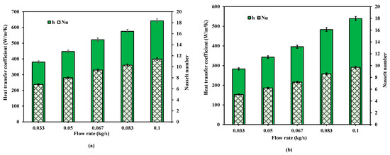
The Nusselt number values were consistently greater than 1, indicating that convection accounted for the majority of the heat transfer. An increase in the average Nusselt number from 6.8 to 11.5 was observed with the flow rate increased from 0.033 kg/s to 0.1 kg/s. It has been raised from 5.1 to 9.7 for a flat-finned receiver. The modified finned receiver has average Nusselt number values that are 33.3%, 29%, 30.7%, 19.8%, and 18.6% higher than those of the flat-fin receiver at 0.033, 0.05, 0.067, 0.083, and 0.1 kg/s, respectively. The modified finned receiver had a higher Nusselt number, resulting in greater useful heat absorption. Figure 10 depicts Nusselt number variation as a function of solar radiation intensity and water flow rate. Figure 11 shows the average h and Nusselt number.
Figure 10.
Nusselt number: (a) Arc-shaped fins; (b) Flat fins.
Figure 11.
Average heat transfer coefficient: (a) Arc-shaped fins; (b) Flat fins.
4.6. Heat Loss
The receiver was covered with a vacuum glass cover to reduce convective and radiative heat losses to the atmosphere. Convective heat loss is a significant heat loss mechanism driven by wind flow. The ha between the glass cover and the atmospheric wind was calculated using Equation (7). In contrast, radiative heat loss was calculated using the sky temperature from Equation (11).
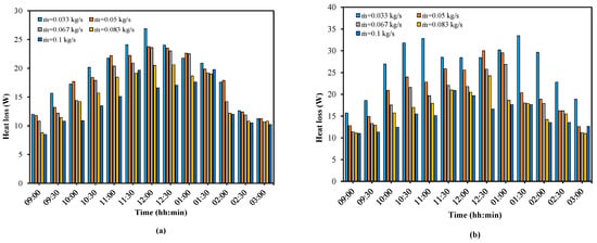
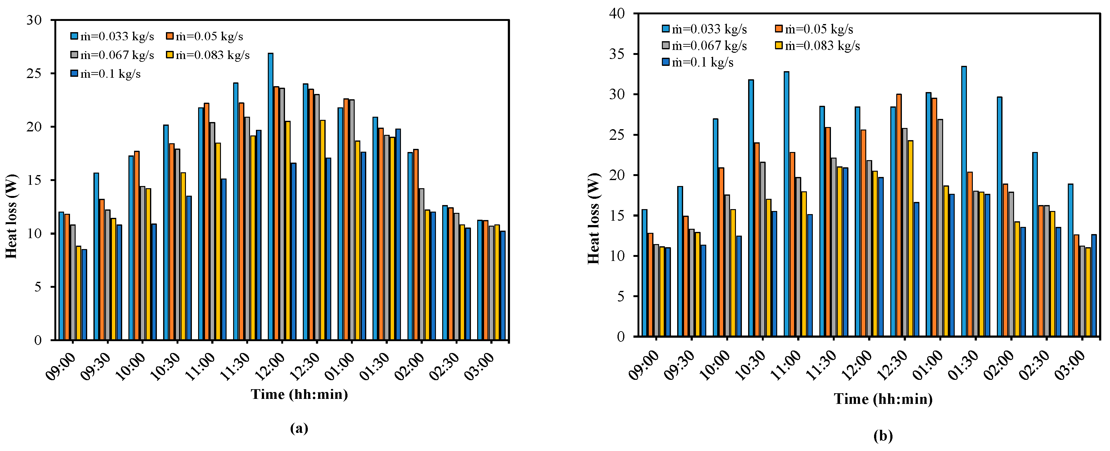
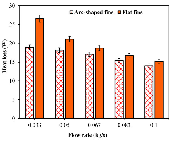
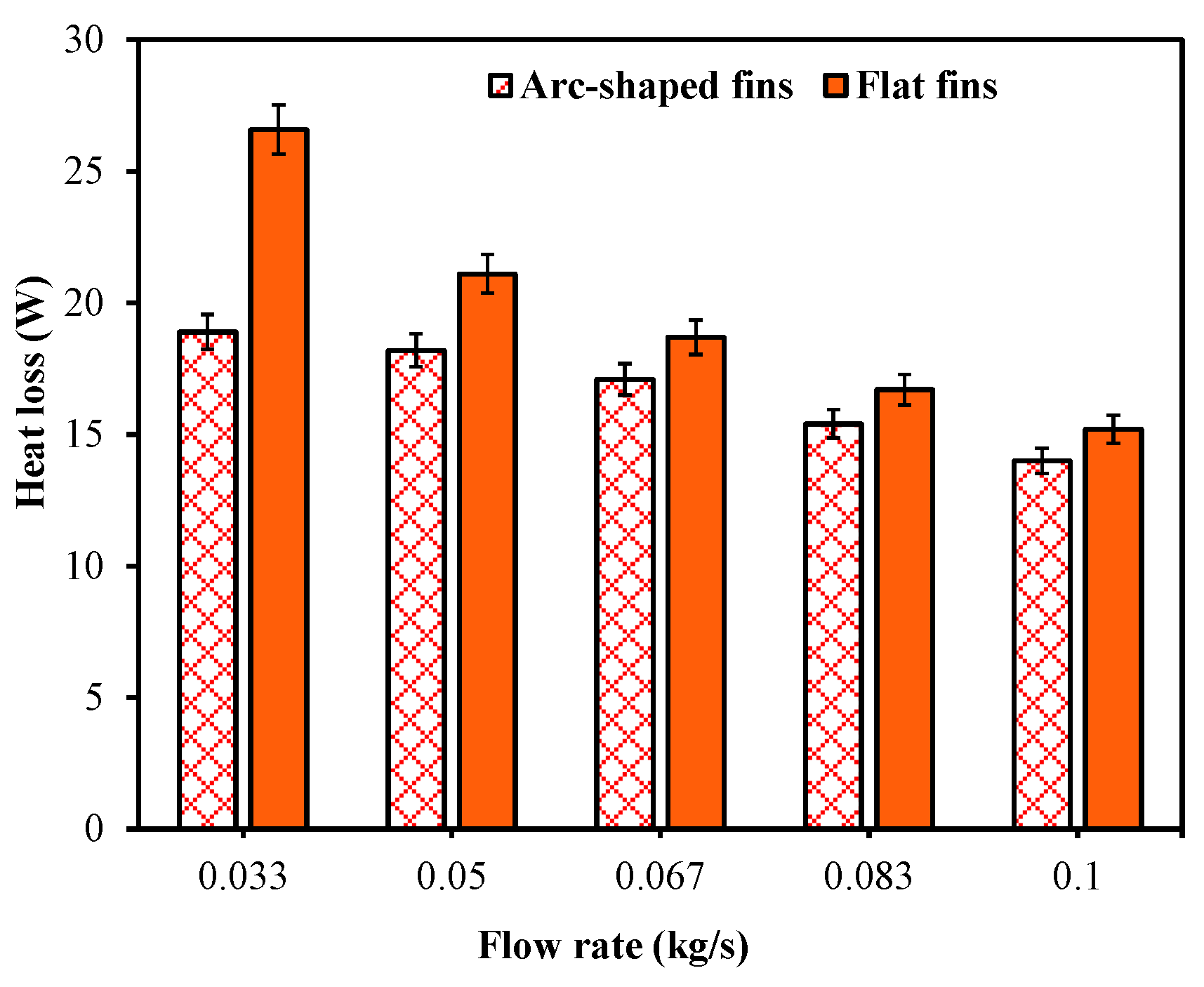
The heat loss was calculated as the sum of the convective and radiative heat losses. When the flow rate increased from 0.033 kg/s to 0.1 kg/s, the average total heat loss for the arc-shaped finned receiver ranged from 14 W to 18.9 W. The same is 26.6 W to 15.2 W for the flat-finned receiver, and 40.7% to 8.5% higher than those of receivers with arc-shaped fins. The reduction in heat loss observed in the arc-shaped receiver can be attributed to its modified geometry. Compared with the flat-finned receiver, the curved fin profile partially encloses the region beneath the receiver, creating a semi-cavity configuration. From a radiation heat transfer perspective, this geometry is expected to increase the likelihood of secondary reflections of concentrated solar radiation before the reflected rays escape into the surroundings, thereby improving the effective utilization of the intercepted solar energy. Consequently, a larger proportion of the intercepted energy is transferred to the working fluid as useful heat, leaving a smaller proportion available for dissipation to the surroundings. This interpretation is consistent with the experimentally observed increase in useful heat gain together with the corresponding reduction in heat loss. Figure 12 and Figure 13 show the variation in heat loss over the course of a day under solar radiation and the decreasing trend in average heat loss as flow rate increases.
Figure 12.
Heat loss of the receiver: (a) Arc-shaped fins; (b) Flat fins.
Figure 13.
Average overall heat loss.
4.7. Thermal Efficiency
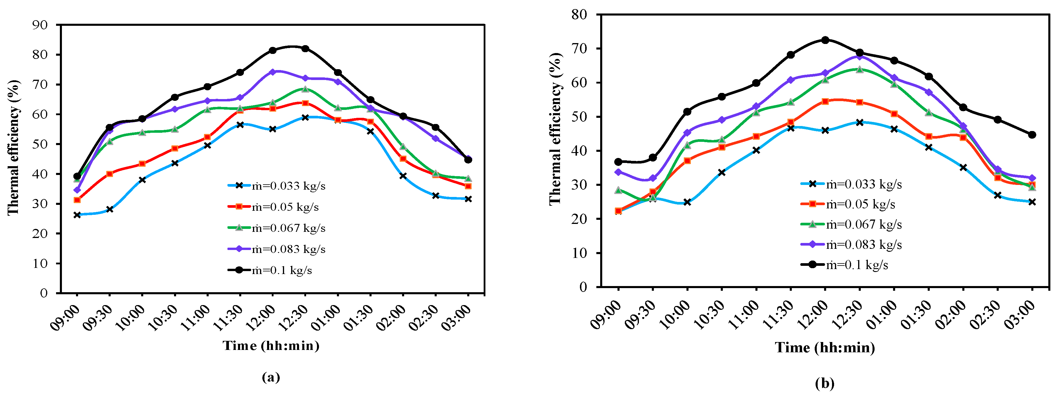
The PTC thermal efficiency is the ratio of the water’s heat gain to the heat input from solar radiation. It is noted that the reported thermal efficiencies are calculated based on the beam solar radiation incident on the collector aperture. Consequently, the observed improvements directly reflect the enhanced overall thermal performance of the arc-shaped receiver under identical incident solar radiation conditions. The superior thermal efficiency of the arc-shaped receiver results from the combined enhancement of solar energy utilization and heat-transfer characteristics. The modified geometry is expected to improve the effective utilization of concentrated solar radiation through the semi-cavity configuration and a larger receiver surface area, while simultaneously promoting greater heat transfer from the receiver to the working fluid. The combined increase in useful heat gain and reduction in thermal losses enable a larger proportion of the intercepted solar energy to be converted into useful thermal energy, as reflected in the experimentally measured improvement in thermal efficiency. Figure 14 depicts the trend in thermal efficiency as solar radiation intensity varies.
Figure 14.
Thermal efficiency: (a) Arc-shaped fins; (b) Flat fins.
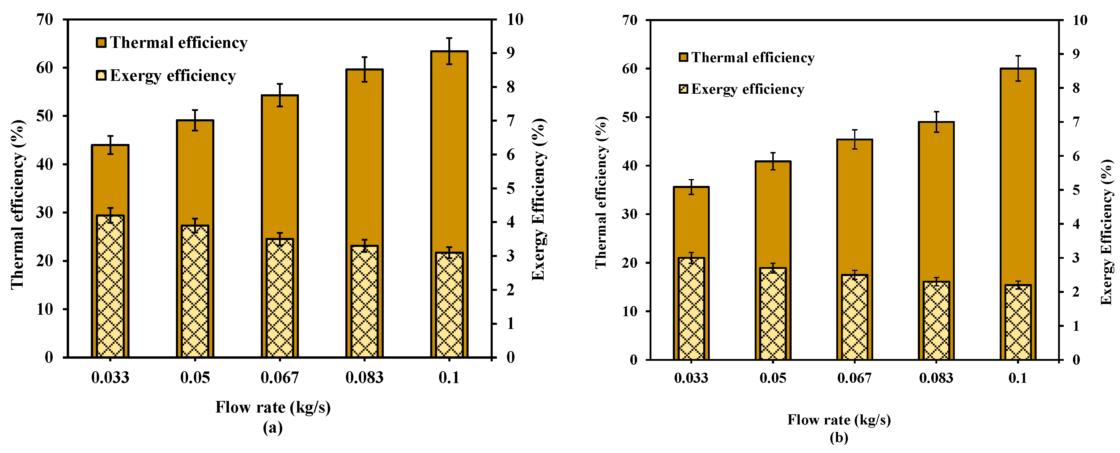
The modified finned receiver achieved an efficiency of 58.9% at 0.033 kg/s. It increases to 63.8%, 65.4%, 72.2%, and 75.8% for increased flow rates to 0.05 kg/s, 0.067 kg/s, 0.083 kg/s, and 0.1 kg/s, respectively. The peak efficiencies for the flat corrugated finned receiver were 48.3%, 54.5%, 64%, 67.6%, and 68.5% at identical flow rates. The average efficiencies are 44%, 49%, 54.3%, 59.6%, and 63.4% for the arc-shaped fins, and 35.6%, 40.9%, 45.4%, 49%, and 55.9% for the flat fins. It increased as the water temperature and flow rate decreased.
4.8. Exergy Efficiency
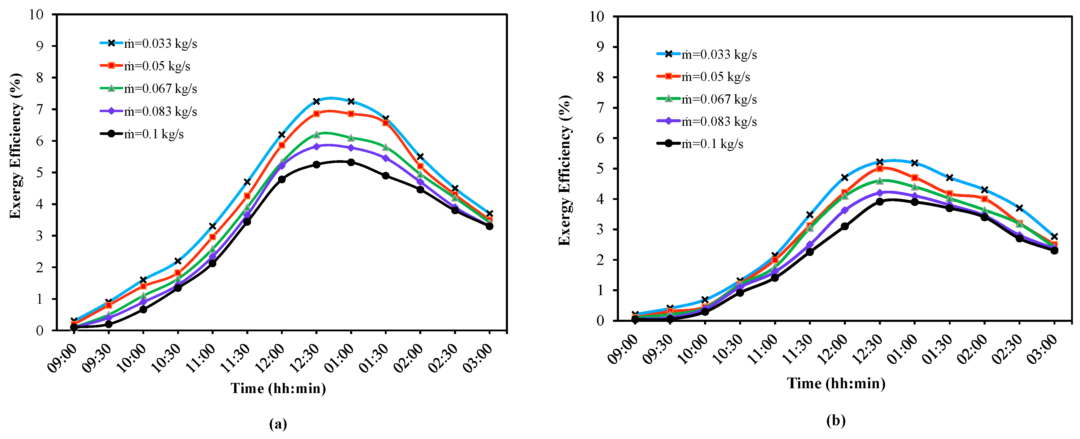
The exergy efficiency is the ratio between the useful exergy and the sun exergy received based on the concentration ratio of the current system. The sun’s exergy is generally computed using the Petela model [46], which assumes that the sun is a hemispherical radiation source. The receiver receives the reflected radiation from the parabolic reflector. Hence, the sun exergy was estimated using the correction factor proposed by Badescu [47]. The correction factor is the ratio of the concentration ratio to the maximum solar radiation concentration in the Earth’s orbit. Figure 15 depicts the variation in the exergy efficiency.
Figure 15.
Exergy efficiency: (a) Arc-shaped fins; (b) Flat fins.
The ratio of the aperture to the receiver area was used to calculate the concentration ratio. A maximum exergy efficiency of 7.3% was attained at 0.033 kg/s, decreasing to 6.9%, 6.2%, 5.8%, and 5.3% at flow rates of 0.05 kg/s, 0.067 kg/s, 0.083 kg/s, and 0.1 kg/s, respectively. A decrease in exergy efficiency was observed at higher flow rates, owing to a smaller difference between the receiver and ambient temperatures resulting from greater usable heat absorption. The highest exergy efficiencies of 5.22%, 5%, 4.6%, 4.2%, and 3.9% were obtained with the modified finned receiver, indicating that efficiency decreased as flow rate increased. When the flow rate is 0.033 kg/s, 0.05 kg/s, 0.067 kg/s, 0.083 kg/s, and 0.1 kg/s, the average exergy efficiency is 4.2%, 3.9%, 3.5%, 3.3%, and 3% for arc-shaped corrugated fins and 3%, 2.7%, 2.5%, 2.3%, and 2.15% for the flat fins. Figure 16 depicts the average energy and exergy efficiencies with increasing and decreasing trends.
Figure 16.
Average efficiency: (a) Arc-shaped fins; (b) Flat fins.
The efficiencies obtained by the other cavity and non-cavity receivers are listed in Table 4. Although the current receiver is simple to construct with a plain receiver tube, an additional arc-like fin structure increases the thermal efficiency. It has a higher thermal efficiency than other configurations, such as cavities, evacuated tubes, corrugated, spiral, rectangular, and internally finned receivers. Furthermore, the current receiver has an exergy efficiency comparable to helical and corrugated receivers and higher than that of other receiver configurations. Hence, the present receiver configuration can improve the current system performance using low-cost materials and simple techniques without increasing the pump power requirement.
4.9. Uncertainty Analysis
An uncertainty analysis was performed to assess the reliability and accuracy of the experimental measurements and the derived thermal performance parameters. The uncertainty estimate was obtained using the uncertainty propagation method proposed by Moffat et al. [48], which accounts for uncertainties in the independently measured variables and their propagation to the calculated parameters. The combined uncertainty of a dependent variable was determined using Equation (21), accounting for the contributions of each independent measurement. The uncertainty of each calculated parameter was evaluated by propagating the uncertainties of the corresponding independent variables. The uncertainty analysis was carried out for all experimental observations, and the average uncertainty obtained from the individual calculations was reported as the representative uncertainty for each calculated performance parameter. The resulting uncertainty values, expressed in both percentage and magnitude terms, are summarized in Table 5.
Here, —General variable, x1, x2,…, xn—Independent variables, and W1, W2…Wn—Uncertainties of the dependent variables.
The maximum uncertainties obtained were ±4.0% for the input solar energy, ±2.0% for the useful heat gain, ±2.0% for the heat transfer coefficient, ±2.0% for the Nu, ±4.3% for the thermal efficiency, and ±5.3% for the exergy efficiency. These uncertainty levels are relatively small compared with the observed performance improvements of the arc-shaped receiver over the flat-finned receiver. Therefore, the experimental uncertainties do not affect the overall trends or conclusions of the present investigation, confirming the reliability and repeatability of the reported results.
Table 4.
Energy and exergy efficiency comparison of the designed solar receiver with previous studies.
Table 5.
Uncertainty analysis of experimental measurements and calculated performance parameters.
5. Discussion
The results of the experiments show that arc-shaped copper-finned tube receivers can significantly improve the thermal and thermodynamic performance of PTC systems compared to flat-finned tube receivers. The geometry results in an arc-shape that serves both as an extended heat absorber and as a secondary reflector to redirect and concentrate the solar radiation to the cavity below the receiver. The simultaneous increase in effective heat transfer area and decrease in radiative energy loss contribute to the outlet water temperature, heat transfer coefficient, Nusselt number, and energy and exergy efficiencies observed in the present study. These results are consistent with those for lower beam types, namely cavity-type, corrugated, and modified receiver geometries [19,21,25], but have the added benefit of using a commercially available copper-finned tube, thereby eliminating the complexity and cost of custom-fabricated receiver designs.
The arc-shaped receiver showed its superiority, especially at low mass flow rates. The receiver with maximum exergy efficiency of 7.25% and thermal efficiency of 58.9% was obtained at 0.033 kg/s, compared with 5.22% and 48.3% for the flat-finned receiver, respectively. This behavior is consistent with the basic laws of heat transfer because, at lower flow rates, the working fluid’s residence time in the receiver is much longer, allowing better heat transfer between the absorber surface and the fluid. As a result, the advantages of the improved cavity geometry grow more significant. The higher mass flow rate (0.1 kg/s) increased the total useful heat gain due to the fluid’s greater heat-carrying capacity, but the relative efficiency advantage of the arc-shaped receiver decreased. The proposed geometry is beneficial for low-flow and high-temperature operation and thus applicable to domestic hot water systems, solar desalination, and low-temperature industrial process heaters.
Heat loss analysis confirms the effectiveness of the arc-shaped configuration. The fins’ curvature creates a thermal enclosure within the cavity, reducing direct radiative and convective heat dissipation to the ambient environment. The cavity region has high local temperatures, but the cavity’s geometric confinement reduces the effective surface area for heat loss and promotes reradiation of heat back to the absorber surface. This behavior has been reported for cavity-type solar receivers and enclosed absorber configurations [24,27]. The findings thus indicate that passive geometric modification of the receiver could be a viable means of reducing heat loss without additional insulation layers, evacuated envelopes, or other high-cost techniques.
The results indicate that the arc-shaped copper fin receiver is a simple, low-cost, and effective solution to improve the thermal efficiency of PTC systems. The enhancements in heat transfer and efficiency noted, along with the simplicity of fabrication and installation, suggest significant promise for practical applications with solar thermal systems.
5.1. Challenges and Limitations
While the findings from the present study were promising, there are some challenges and limitations to be noted when interpreting the findings:
- The experiments were conducted outdoors in March–April 2023. Uncertainties were inevitable because solar radiation, ambient temperature, and wind speed changed during the measurements. Data fluctuations were minimized by averaging, but specific operating conditions during outdoor solar testing are not repeatable due to environmental variability.
- The operating temperature range was very limited, as the HTF was water only and the current experimental setup allowed only a maximum outlet temperature of about 80 °C. It can be used for domestic water heating and low- to medium-temperature thermal applications, but is not adequate for many medium- and high-temperature industrial processes.
- Thermal cycling, UV exposure, environmental exposure and weathering were not assessed for long-term effects on the copper fins and the coating on the absorber. As copper oxidizes and coatings deteriorate and become contaminated by environmental exposure, the solar absorptivity may decrease over time, as may the heat transfer properties, which can impact system performance.
- The pressure drop aspect of the thermo-hydraulic performance of the finned receiver has not been fully explored. Flow resistance and pumping power requirements may be higher due to the added surface features, especially at higher mass flow rates. The improved receiver geometry would partially mitigate these hydraulic penalties.
- The research was carried out under a specific receiver geometry, a range of flow rates, and local climatic conditions. Hence, these results must be validated at other geographic sites, during different seasons, and in larger-scale systems.
5.2. Future Research Directions
To improve the performance and usefulness of the proposed receiver design, the following research directions are recommended:
- Explore selective absorber coatings specifically designed for arc-shaped receiver geometries, with high solar absorption and low infrared emissivity to further reduce radiative heat losses.
- Formulate and validate computational fluid dynamics and heat transfer models and optical ray-tracing models using current experimental data. These models can be used to optimize the fin curvature, cavity depth, fin spacing, and receiver size in detail.
- Study of thermal oils, synthetic thermal oils, and nanofluids such as Al2O3/water and TiO2/water. The overall improvement in fluid thermal properties and the receiver’s improved geometry could also yield further performance gains.
- Multi-season outdoor test to assess corrosion resistance, coating stability, thermal fatigue and optical degradation under realistic outdoor conditions.
- Determine the characteristics of pressure drop, pumping power requirement, and the overall system’s coefficient of performance to provide a complete evaluation of receiver efficiency.
- Conduct economic feasibility analysis and life-cycle assessment of the proposed receiver compared to conventional absorber designs, and assess their commercial feasibility.
- Consider combining optical enhancements, such as secondary reflective coatings and concentrator modifications, with thermal enhancements, such as porous inserts, turbulence promoters, and thermal energy storage technologies.
- Test the performance of arc-shaped receivers in larger PTC systems and assess their feasibility for commercial industrial process heating, solar desalination, power generation and other industrial solar thermal applications.
6. Conclusions
This experimental study investigated the thermal and exergy performance of a PTC equipped with commercially available flat-finned and arc-shaped copper-finned receivers over the mass flow rate range of 0.033–0.10 kg s−1. The performance of flat-finned and arc-shaped finned receivers was evaluated, and the major findings are summarized as follows.
- The flat-finned receiver delivered outlet water temperatures ranging from 64 °C to 72 °C as the mass flow rate varied from 0.1 kg/s to 0.033 kg/s. Replacing the flat fins with arc-shaped fins increased the outlet water temperature to 67–80 °C under the same mass flow rate conditions, attributed to enhanced solar radiation absorption.
- The temperature difference between the inlet and outlet was minimal at higher flow rates, despite greater useful heat absorption. The maximum temperature differences recorded were 6.5 °C and 5.0 °C for the arc-shaped and flat-finned receivers, respectively.
- Lower outlet water temperatures were observed at higher flow rates due to increased useful heat gain. The arc-shaped fin geometry, due to its modified profile, enabled the receiver to attain higher maximum temperatures than the flat-finned configuration.
- Within the investigated mass flow rate range (0.033–0.10 kg s−1), replacing the flat-finned receiver with the arc-shaped finned receiver reduced the system heat loss by 8.4–40.7%. This improvement is attributed to the heated cavity zone of the arc-shaped fin, which enhances heat transfer to the working fluid while minimizing thermal losses.
- A maximum heat transfer coefficient of 642 W/m2K was achieved with the arc-shaped finned receiver, representing a 19% improvement over the flat-finned receiver at 0.1 kg/s. Correspondingly, the Nusselt number of the arc-shaped finned receiver was 18.6–33.3% higher, indicating enhanced convective heat transfer with the working fluid.
- At 0.1 kg/s, the arc-shaped finned receiver achieved peak and average thermal efficiencies of 75.8% and 63.4%, respectively, representing improvements of approximately 10% and 11% over the flat-finned receiver under the same operating conditions.
- At 0.033 kg/s, the arc-shaped finned receiver attained peak and average exergy efficiencies of 7.25% and 4.16%, respectively, which are 38.9% and 39.6% greater than those of the flat-finned receiver, further demonstrating its thermodynamic superiority.
Based on the experimental investigation conducted over the mass flow rate range of 0.033–0.10 kg s−1, the arc-shaped copper-finned receiver consistently exhibited superior thermal and exergy performance compared with the flat-finned receiver. These findings indicate that the proposed receiver geometry is a promising, commercially viable approach to improving the performance of PTCs operating under similar conditions. However, future studies may include a comprehensive thermo-hydraulic assessment to experimentally verify the influence of the proposed receiver configuration on the overall system performance. Further investigations should focus on detailed optical ray tracing and coupled thermo-optical analyses, along with receiver optimization across a broader operating range, to enhance the design and performance of the proposed receiver.
Author Contributions
Conceptualization, R.S. and C.S.; methodology, R.S., M.R.M. and C.S.; formal analysis, R.S., M.R.M., E.V. and C.S.; investigation, R.S., M.R.M. and C.S.; validation, R.S. and C.S.; visualization, E.V.; writing—original draft preparation, R.S., M.R.M. and C.S.; writing—review and editing, R.S., E.V. and C.S. All authors have read and agreed to the published version of the manuscript.
Funding
This research received no external funding.
Institutional Review Board Statement
Not applicable.
Informed Consent Statement
Not applicable.
Data Availability Statement
The raw data supporting the conclusions of this article will be made available by the authors on request.
Acknowledgments
The authors thank SRM Institute of Science and Technology, Kattankulathur, Chennai, India, for providing the necessary research infrastructure.
Conflicts of Interest
The authors declare no conflicts of interest.
Nomenclature
| Symbols | |
| Aa | Aperture area of the solar collector (m2) |
| Ac | The cross-section area of the receiver (m2) |
| Aco | Surface area of the outer cover (m2) |
| Cmax | Maximum solar radiation concentration at Earth Orbit |
| Cp | Specific heat of water (J/kgK) |
| CR | Concentration ratio |
| Dco | Glass cover diameter (m) |
| Dh | Hydraulic diameter (m) |
| Dri | Receiver’s internal diameter (m) |
| Ėxloss | Exergy loss (W) |
| Ėxs | Exergy due to input solar radiation (W) |
| Ėxu | Useful exergy (W) |
| Ėxw,in | Exergy of inlet water (W) |
| Ėxw,out | Exergy of outlet water (W) |
| fH | Correction factor |
| Gb | Solar beam radiation intensity (W/m2) |
| h | Convective heat transfer coefficient (W/m2K) |
| ha | Heat loss coefficient of wind (W/m2K) |
| k | Thermal conductivity (W/mK) |
| L | Length (m) |
| ṁ | Mass flow rate of water (kg/s) |
| Nu | Nusselt number |
| P | Perimeter (m) |
| Qloss | Total heat loss (W) |
| Qloss,conv | Heat loss by convection (W) |
| Qloss,rad | Heat loss by radiation (W) |
| Qs,in | Input solar energy (W) |
| Qu | Useful energy (W) |
| Qw,in | Inlet water energy (W) |
| Qw,out | Outlet water energy (W) |
| Ta | Ambient temperature (K) |
| Tc | Glass cover temperature (K) |
| Tfm | Mean temperature (K) |
| Ti | Inlet water temperature (°C) |
| To | Outlet water temperature (°C) |
| Tr | Receiver temperature (K) |
| Tsky | Sky temperature (K) |
| Tsun | Sun temperature (K) |
| Vwind | Wind velocity (m/s) |
| W | Width of the reflector (m) |
| ΔP | Pressure drop (Pa) |
| Greek Symbol | |
| ɛc | Emissivity of outer cover |
| ηth | Thermal efficiency (%) |
| ηex | Exergy efficiency (%) |
| ρ | Density (kg/m3) |
| σ | Boltzmann constant (W/m2 K4) |
| Abbreviation | |
| HTF | Heat transfer fluid |
| PTC | Parabolic trough collector |
| Subscripts | |
| a | Ambient, aperture |
| b | Beam |
| c | cover |
| co | Outer glass cover |
| conv | Convective |
| en | Energy |
| ex | Exergy |
| h | Hydraulic |
| i | inlet |
| r | Receiver |
| rad | Radiative |
| ri | Receiver inner |
| w | Water |
References
- Gobio-Thomas, L.B.; Darwish, M.; Stojceska, V. Environmental impacts of solar thermal power plants used in industrial supply chains. Therm. Sci. Eng. Prog. 2023, 38, 101670. [Google Scholar] [CrossRef] [Scilit]
- Achkari, O.; El Fadar, A. Latest developments on TES and CSP technologies—Energy and environmental issues, applications and research trends. Appl. Therm. Eng. 2020, 167, 114806. [Google Scholar] [CrossRef] [Scilit]
- Alam, M.I.; Nuhash, M.M.; Zihad, A.; Nakib, T.H.; Ehsan, M.M. Conventional and Emerging CSP Technologies and Design Modifications: Research Status and Recent Advancements. Int. J. Thermofluids 2023, 20, 100406. [Google Scholar] [CrossRef] [Scilit]
- Burkhardt, J.J., III; Heath, G.A.; Turchi, C.S. Life Cycle Assessment of a Parabolic Trough Concentrating Solar Power Plant and the Impacts of Key Design Alternatives. Environ. Sci. Technol. 2011, 45, 2457–2464. [Google Scholar] [CrossRef] [Scilit] [PubMed]
- Guillén-Lambea, S.; Carvalho, M. A critical review of the greenhouse gas emissions associated with parabolic trough concentrating solar power plants. J. Clean. Prod. 2021, 289, 125774. [Google Scholar] [CrossRef] [Scilit]
- Hu, T.; Kwan, T.H.; Zhang, H.; Wang, Q.; Pei, G. Thermal performance investigation of the newly shaped vacuum tubes of parabolic trough collector system. Energy 2023, 278, 127802. [Google Scholar] [CrossRef] [Scilit]
- Fattahi, A. The effect of cross-section geometry on the performance of a solar nanofluid heater in a parabolic solar receiver: A comparison study. J. Taiwan Inst. Chem. Eng. 2021, 124, 17–28. [Google Scholar] [CrossRef] [Scilit]
- Vengadesan, E.; Thameenansari, S.; Manikandan, E.J.; Senthil, R. Experimental study on heat transfer enhancement of parabolic trough solar collector using a rectangular channel receiver. J. Taiwan Inst. Chem. Eng. 2022, 135, 104361. [Google Scholar] [CrossRef] [Scilit]
- Liu, P.; Dong, Z.; Xiao, H.; Liu, Z.; Liu, W. A novel parabolic trough receiver by inserting an inner tube with a wing-like fringe for solar cascade heat collection. Renew. Energy 2021, 170, 327–340. [Google Scholar] [CrossRef] [Scilit]
- Motwani, K.; Chotai, N.; Patel, J.; Hadiya, R. Design and experimental investigation on cut tube absorber for solar parabolic trough collector. Energy Sources Part A Recovery Util. Environ. Eff. 2020, 46, 9173–9192. [Google Scholar] [CrossRef] [Scilit]
- Bellos, E.; Tzivanidis, C.; Tsimpoukis, D. Multi-criteria evaluation of parabolic trough collector with internally finned absorbers. Appl. Energy 2017, 205, 540–561. [Google Scholar] [CrossRef] [Scilit]
- Bellos, E.; Tzivanidis, C.; Tsimpoukis, D. Thermal enhancement of parabolic trough collector with internally finned absorbers. Sol. Energy 2017, 157, 514–531. [Google Scholar] [CrossRef] [Scilit]
- Vahidinia, F.; Khorasanizadeh, H.; Aghaei, A. Energy, exergy, economic and environmental evaluations of a finned absorber tube parabolic trough collector utilizing hybrid and mono nanofluids and comparison. Renew. Energy 2023, 205, 185–199. [Google Scholar] [CrossRef] [Scilit]
- Liang, H.; Zhu, C.; Fan, M.; You, S.; Zhang, H.; Xia, J. Study on the thermal performance of a novel cavity receiver for parabolic trough solar collectors. Appl. Energy 2018, 222, 790–798. [Google Scholar] [CrossRef] [Scilit]
- Pazarlıoğlu, H.K.; Ekiciler, R.; Arslan, K.; Mohammed Mohammed, N.A. Exergetic, Energetic, and entropy production evaluations of parabolic trough collector retrofitted with elliptical dimpled receiver tube filled with hybrid nanofluid. Appl. Therm. Eng. 2023, 223, 120004. [Google Scholar] [CrossRef] [Scilit]
- Al-Rabeeah, A.Y.; Seres, I.; Farkas, I. Experimental investigation of improved parabolic trough solar collector thermal efficiency using novel receiver geometry design. Int. J. Thermofluids 2023, 18, 100344. [Google Scholar] [CrossRef] [Scilit]
- Hamada, M.A.; Ehab, A.; Khalil, H.; Abou Al-Sood, M.M.; Sharshir, S.W. Thermal performance augmentation of parabolic trough solar collector using nanomaterials, fins and thermal storage material. J. Energy Storage 2023, 67, 107591. [Google Scholar] [CrossRef] [Scilit]
- Chakraborty, O.; Roy, S.; Das, B.; Gupta, R. Effects of helical absorber tube on the energy and exergy analysis of parabolic solar trough collector—A computational analysis. Sustain. Energy Technol. Assess. 2021, 44, 101083. [Google Scholar] [CrossRef] [Scilit]
- Akbarzadeh, S.; Valipour, M.S. The thermo-hydraulic performance of a parabolic trough collector with helically corrugated tube. Sustain. Energy Technol. Assess. 2021, 44, 101013. [Google Scholar] [CrossRef] [Scilit]
- Wang, W.; Zhang, Y.; Li, B.; Li, Y. Numerical investigation of tube-side fully developed turbulent flow and heat transfer in outward corrugated tubes. Int. J. Heat Mass Transf. 2018, 116, 115–126. [Google Scholar] [CrossRef] [Scilit]
- Akbarzadeh, S.; Valipour, M.S. Energy and exergy analysis of a parabolic trough collector using helically corrugated absorber tube. Renew. Energy 2020, 155, 735–747. [Google Scholar] [CrossRef] [Scilit]
- Babapour, M.; Akbarzadeh, S.; Valipour, M.S. An experimental investigation on the simultaneous effects of helically corrugated receiver and nanofluids in a parabolic trough collector. J. Taiwan Inst. Chem. Eng. 2021, 128, 261–275. [Google Scholar] [CrossRef] [Scilit]
- Bellos, E.; Tzivanidis, C. Alternative designs of parabolic trough solar collectors. Prog. Energy Combust. Sci. 2019, 71, 81–117. [Google Scholar] [CrossRef] [Scilit]
- Kalidasan, B.; Hassan, M.A.; Pandey, A.K.; Chinnasamy, S. Linear cavity solar receivers: A review. Appl. Therm. Eng. 2023, 221, 119815. [Google Scholar] [CrossRef] [Scilit]
- Loni, R.; Ghobadian, B.; Kasaeian, A.B.; Akhlaghi, M.M.; Bellos, E.; Najafi, G. Sensitivity analysis of parabolic trough concentrator using rectangular cavity receiver. Appl. Therm. Eng. 2020, 169, 114948. [Google Scholar] [CrossRef] [Scilit]
- Mohamad, K.; Ferrer, P. Thermal performance and design parameters investigation of a novel cavity receiver unit for parabolic trough concentrator. Renew. Energy 2021, 168, 692–704. [Google Scholar] [CrossRef] [Scilit]
- Li, X.; Chang, H.; Duan, C.; Zheng, Y.; Shu, S. Thermal performance analysis of a novel linear cavity receiver for parabolic trough solar collectors. Appl. Energy 2019, 237, 431–439. [Google Scholar] [CrossRef] [Scilit]
- Vengadesan, E.; Rumaney, A.R.I.; Mitra, R.; Harichandan, S.; Senthil, R. Heat transfer enhancement of a parabolic trough solar collector using a semicircular multitube absorber. Renew. Energy 2022, 196, 111–124. [Google Scholar] [CrossRef] [Scilit]
- Goel, A.; Mahadeva, R.; Manik, G. Analysis and Optimization of Parabolic Trough Solar Collector to Improve Its Optical Performance. J. Sol. Energy Eng. 2023, 145, 031009. [Google Scholar] [CrossRef] [Scilit]
- Bellos, E.; Tzivanidis, C. Enhancing the performance of a parabolic trough collector with combined thermal and optical techniques. Appl. Therm. Eng. 2020, 164, 114496. [Google Scholar] [CrossRef] [Scilit]
- Wang, Q.; Yang, H.; Zhong, S.; Huang, Y.; Hu, M.; Cao, J.; Pei, G.; Yang, H. Comprehensive experimental testing and analysis on parabolic trough solar receiver integrated with radiation shield. Appl. Energy 2020, 268, 115004. [Google Scholar] [CrossRef] [Scilit]
- Wang, Q.; Yang, H.; Huang, X.; Li, J.; Pei, G. Numerical investigation and experimental validation of the impacts of an inner radiation shield on parabolic trough solar receivers. Appl. Therm. Eng. 2018, 132, 381–392. [Google Scholar] [CrossRef] [Scilit]
- El-Bakry, M.M.; Kassem, M.A.; Hassan, M.A. Passive performance enhancement of parabolic trough solar concentrators using internal radiation heat shields. Renew. Energy 2021, 165, 52–66. [Google Scholar] [CrossRef] [Scilit]
- Qiu, Y.; Zhang, Y.; Li, Q.; Xu, Y.; Wen, Z. A novel parabolic trough receiver enhanced by integrating a transparent aerogel and wing-like mirrors. Appl. Energy 2020, 279, 115810. [Google Scholar] [CrossRef] [Scilit]
- Vishnu, S.K.; Senthil, R. Experimental performance evaluation of a solar parabolic dish collector using spiral flow path receiver. Appl. Therm. Eng. 2023, 231, 120979. [Google Scholar] [CrossRef] [Scilit]
- Darbari, B.; Derikvand, M.; Shabani, B. Thermal performance improvement of a LS-2 parabolic trough solar collector using porous disks. Appl. Therm. Eng. 2023, 228, 120546. [Google Scholar] [CrossRef] [Scilit]
- Saedodin, S.; Zaboli, M.; Ajarostaghi, S.S.M. Hydrothermal analysis of heat transfer and thermal performance characteristics in a parabolic trough solar collector with turbulence-inducing elements. Sustain. Energy Technol. Assess. 2021, 46, 101266. [Google Scholar] [CrossRef] [Scilit]
- Sarangi, A.; Sarangi, A.; Sahoo, S.S.; Mallik, R.K.; Ray, S.; Varghese, S.M. A review of different working fluids used in the receiver tube of parabolic trough solar collector. J. Therm. Anal. Calorim. 2023, 148, 3929–3954. [Google Scholar] [CrossRef] [Scilit]
- Awan, A.B.; Khan, M.N.; Zubair, M.; Bellos, E. Commercial parabolic trough CSP plants: Research trends and technological advancements. Sol. Energy 2020, 211, 1422–1458. [Google Scholar] [CrossRef] [Scilit]
- Ngo, L.C.; Bello-Ochende, T.; Meyer, J.P. Three-dimensional analysis and numerical optimization of combined natural convection and radiation heat loss in solar cavity receiver with plate fins insert. Energy Convers. Manag. 2015, 101, 757–766. [Google Scholar] [CrossRef] [Scilit]
- Senthil, R. Effect of charging of phase change material in vertical and horizontal rectangular enclosures in a concentrated solar receiver. Case Stud. Therm. Eng. 2020, 21, 100653. [Google Scholar] [CrossRef] [Scilit]
- Prabhu, B.; Vengadesan, E.; Senthil, S.; Arunkumar, T. Comprehensive energy and enviro-economic performance analysis of a flat plate solar water heater with a modified absorber. Therm. Sci. Eng. Prog. 2024, 54, 102848. [Google Scholar] [CrossRef] [Scilit]
- Bhowmik, N.C.; Mullick, S.C. Calculation of tubular absorber heat loss factor. Sol. Energy 1985, 35, 219–225. [Google Scholar] [CrossRef] [Scilit]
- Swinbank, W.C. Long-wave radiation from clear skies. Q. J. R. Meteorol. Soc. 1963, 89, 339–340. [Google Scholar] [CrossRef] [Scilit]
- Caliskan, H. Energy, exergy, environmental, enviroeconomic, exergoenvironmental (EXEN) and exergoenviroeconomic (EXENEC) analyses of solar collectors. Renew. Sustain. Energy Rev. 2017, 69, 488–492. [Google Scholar] [CrossRef] [Scilit]
- Petela, R. Exergy of undiluted thermal radiation. Sol. Energy 2003, 74, 469–488. [Google Scholar] [CrossRef] [Scilit]
- Badescu, V. How much work can be extracted from diluted solar radiation? Sol. Energy 2018, 170, 1095–1100. [Google Scholar] [CrossRef] [Scilit]
- Moffat, R.J. Describing the uncertainties in experimental results. Exp. Therm. Fluid Sci. 1988, 1, 3–17. [Google Scholar] [CrossRef] [Scilit]
- Bellos, E.; Daniil, I.; Tzivanidis, C. Multiple cylindrical inserts for parabolic trough solar collector. Appl. Therm. Eng. 2018, 143, 80–89. [Google Scholar] [CrossRef] [Scilit]
- Yılmaz, İ.H.; Mwesigye, A.; Göksu, T.T. Enhancing the overall thermal performance of a large aperture parabolic trough collector using wire coil inserts. Sustain. Energy Technol. Assess. 2020, 39, 100696. [Google Scholar] [CrossRef] [Scilit]

Disclaimer/Publisher’s Note: The statements, opinions and data contained in all publications are solely those of the individual author(s) and contributor(s) and not of MDPI and/or the editor(s). MDPI and/or the editor(s) disclaim responsibility for any injury to people or property resulting from any ideas, methods, instructions or products referred to in the content. |
© 2026 by the authors. Licensee MDPI, Basel, Switzerland. This article is an open access article distributed under the terms and conditions of the Creative Commons Attribution (CC BY) license.