


Abstract
Slope stability in open-pit mining is not a static condition but evolves continuously as excavation progresses and geomechanical conditions change. In this study, an integrated approach combining ground-based radar monitoring, satellite-based InSAR time-series analysis, and numerical stability modeling was applied to evaluate slope behavior in a large-scale open-pit copper mine with complex geological and structural characteristics. Radar data revealed progressive and episodic deformation concentrated in specific slope sectors, while InSAR observations showed that deformation continued at lower rates after the main movement phase, providing a longer-term perspective of slope response. Stability analyses using limit equilibrium and finite element methods indicate that the slope operates close to a limit equilibrium condition, particularly under saturated scenarios where factors of safety approach critical levels and strain localization becomes more pronounced. The results show a clear link between observed deformation patterns and calculated stability conditions, with structural discontinuities and groundwater playing a dominant role in controlling slope behavior. Based on these findings, an integrated workflow is proposed that links monitoring data with stability assessment, enabling the identification of critical zones and supporting the evaluation of slope conditions during ongoing mining operations. This approach contributes to more reliable decision-making and supports safer and more sustainable open-pit mining practices.
1. Introduction
Mineral resources, which aid in infrastructure development and energy transition technologies, are critical for the global economy. Open-pit mining is the dominant surface mining technique for most metals because of the operating efficiency and production rate that can be achieved.
Slope stability during open-pit mining is a dynamic geomechanical state influenced by the redistribution of stresses due to excavation, rock mass strength parameters, structural discontinuities and groundwater regime. As material is removed in a systematic fashion, the rock surrounding becomes less confined and shear stresses tend to localize within pre-existing weakness planes. This process can lead to localized failures as well as more widespread, large-scale collapses. Accordingly, stability is not only affected by geometrical design parameters like the overall slope angle and bench arrangements, but also by complex interactions among geotechnical and hydrogeological conditions, material heterogeneity and mining sequence. As the pit wall performance has a significant impact not only on operational safety, but also on equipment exposure and stripping ratios along with long-term economic limits, slope stability evaluation becomes part of design as well as real-time mine management rather than a one-time analytical exercise.
Assessing open-pit slope stability can involve a dual track of engineering analyses which quantify potential failure, and field measurements that show how the wall behaves in practice during mining. Typical analysis approaches include limit equilibrium analyses that provide factors of safety (FoS) for different conditions. Conversely, numerical methods allow for investigation of stress redistribution patterns, deformation response, and strength-reduction-type stability indices. Because excavation stages and groundwater conditions change, monitoring becomes the controlling feedback mechanism. Surface movements are monitored using total station prisms and GNSS points, whereas internal deformation is measured by inclinometers, extensometers, and time domain reflectometry (TDR) cables. Pore-pressure variations are monitored using piezometers. For continuous, distributed, and spatially related monitoring systems are typically in the form of ground-based slope monitoring radar systems, which provide real-time deformation measurements. Satellite InSAR on the other hand provides information on a longer temporal scale, covering larger areas. Combined application of these datasets allows for the interpretation of displacement rates and their acceleration, as well as supports calibration of stability models in an operational ground control workflow.
Most recently, research for open-pit slope engineering has gradually transitioned from a purely geometrical safety assessment of the slopes toward mechanism-based interpretation of deformation response. Previous studies have shown that mining-induced slope displacements are strongly influenced by the spatial interconnectivity of weak rock zones, and that deformation patterns should not be interpreted independently of the structural continuity of the rock mass [1]. In this context, the geometry and orientation of potential release surfaces become critical in controlling slope kinematics and associated failure mechanisms in structurally complex environments [2]. This highlights the need to explicitly incorporate discontinuity driven mechanisms into stability modeling frameworks.
Moreover, hydrogeological forcing has emerged as a central theme involving destabilization beyond structural controls such as clay layers. Previous studies have shown that shear mechanisms in open-pit environments are strongly influenced by groundwater conditions, with pore-pressure playing a critical role in controlling slope stability [3]. Their results emphasize that pore-pressure evolution can strongly alter the shear resistance along pre-existing weakness planes. Geotechnical conditions are among the key challenges in large-scale surface mining, and long-term assessment of slope performance is required to ensure operational continuity and sustainable production [4]. Furthermore, deformation mechanisms in open-pit systems involving underground extraction have been shown to be influenced by additional stress redistribution associated with multi-stage excavation, which increases the complexity of slope response prediction [5].
Recent studies emphasize the importance of integrating monitoring data with numerical modeling approaches to improve the interpretation of slope behavior in open-pit mining environments. However, a systematic review of slope monitoring techniques published a few years ago showed that whilst these methods can provide high-resolution deformation data to help bring geomorphology and geology together, the role of ground-based radar and satellite InSAR systems is increasingly being recognized as playing an important part in pattern recognition of deformation events between extremely early warning activities [6]. Numerical studies, which complement theoretical research, show that the optimal or calibrated parameters can have a significant effect on the predicted stability of large scale open-pit slopes as different excavation phases are approached [7]. Furthermore, the use of satellite time-series-assisted InSAR analysis is being applied in monitoring longer deformation trends in order to produce reliable estimates of surface mining displacement [8].
Recent studies have approached open-pit and slope deformation problems from related but different perspectives. InSAR-based studies have shown that satellite observations can identify deformation trends, precursory displacement behavior, and long-term slope movement patterns [9,10]. Other studies have focused on the feasibility and limitations of InSAR monitoring under complex terrain, vegetation, and deformation-gradient conditions [11], while data-driven and numerical approaches have been used to estimate safety factors or potential failure surfaces from slope geometry and strength parameters [12]. These studies demonstrate the value of remote sensing and stability assessment methods; however, they generally treat deformation detection, deformation prediction, monitoring feasibility, or stability estimation as separate tasks.
The novelty of the present study is therefore not the isolated use of radar, InSAR, limit equilibrium analysis, or finite element modeling. The study does not aim to introduce a new InSAR processing algorithm or a new numerical stability method. Its contribution lies in organizing these components within a retrospective, monitoring-based ground control framework that links short-term radar-derived displacement behavior, longer-term InSAR deformation trends, and FoS/SRF-based stability indicators within the same engineering interpretation process. In this sense, the proposed workflow is intended as a decision-support procedure for operational open-pit slope management, allowing critical zones to be identified, interpreted, and reassessed using both monitoring evidence and calculated stability conditions.
2. Study Area and Geological Setting
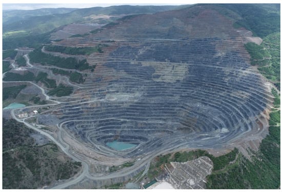
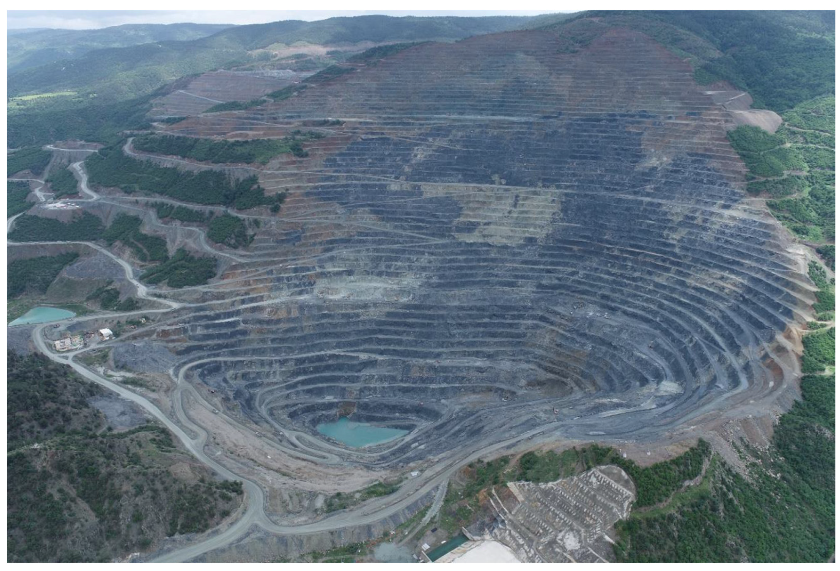
The study was conducted in an open-pit copper mine located in northern Türkiye. The mine is characterized by a complex slope geometry, heterogeneous lithological units, and structurally controlled rock mass conditions, making it particularly critical with respect to slope stability. The operation produces approximately 2 Mt of ore per year from a highwall reaching nearly 700 m in height, highlighting the importance of maintaining stable slope conditions for safe and continuous operation during ongoing mining activities. The open-pit geometry has evolved through successive excavation stages, exposing different lithological units and structural features that significantly influence slope performance (Figure 1).
Figure 1.
General view of the open-pit mine and slope geometry.
These units are interpreted to represent remnants of an arc–back-arc system associated with the Mesozoic evolution of the northern Anatolian margin [13]. Subsequent compressional tectonic activity and regional metamorphism under greenschist facies conditions led to the development of well-defined foliation and localized shear zones, which play a significant role in controlling slope behavior [14,15].
The lithological assemblage consists of chlorite–epidote schists, phyllite units, and metamorphosed basaltic layers, all exhibiting pronounced anisotropy due to the presence of foliation planes and tectonic discontinuities. Structural mapping indicates that predominantly NW-dipping foliation planes and tectonic contacts govern the mechanical response of the slope at a larger scale.
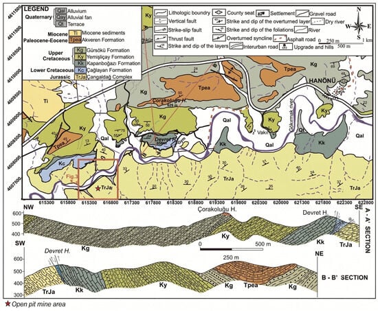
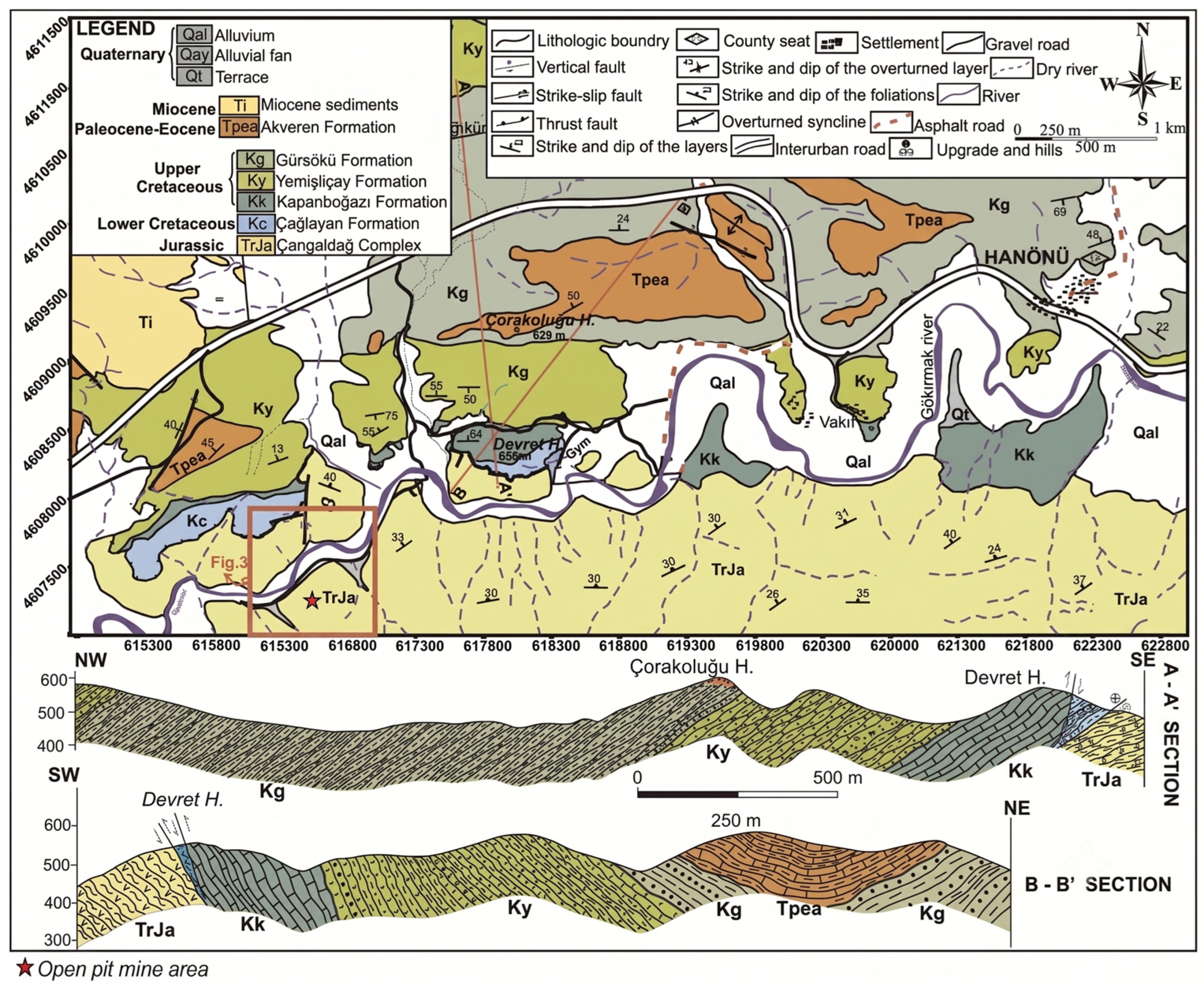
The mine is situated within the Central Pontides tectonic belt, which is characterized by low-grade metamorphic units and tectonically imbricated sequences (Figure 2). The geological framework mainly consists of meta-volcanoclastic units with interbedded mafic layers and associated phyllite and schist units, as well as locally occurring metasedimentary rocks derived from black shale [13,14].
Figure 2.
Geological framework of the study area [14].
As mining progressed to deeper levels, the interaction between structural discontinuities, weathering profiles, and groundwater conditions became increasingly important in controlling slope stability. Therefore, a well-defined geological and structural framework is essential for stability analysis and for the interpretation of deformation mechanisms observed in this study.
3. Methodology
An integrated methodological framework was adopted to evaluate slope stability by combining deformation monitoring techniques with numerical analysis. The approach is based on the joint interpretation of ground-based radar data, satellite-based InSAR measurements, and stability modeling results.
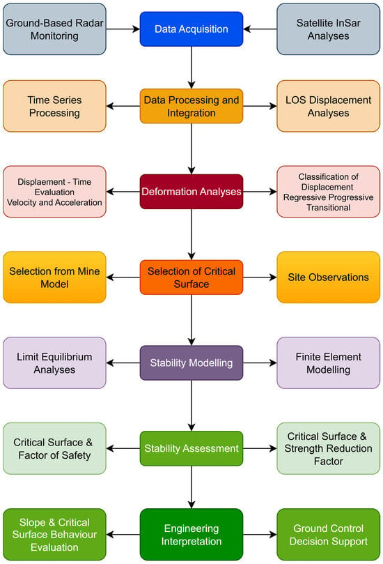
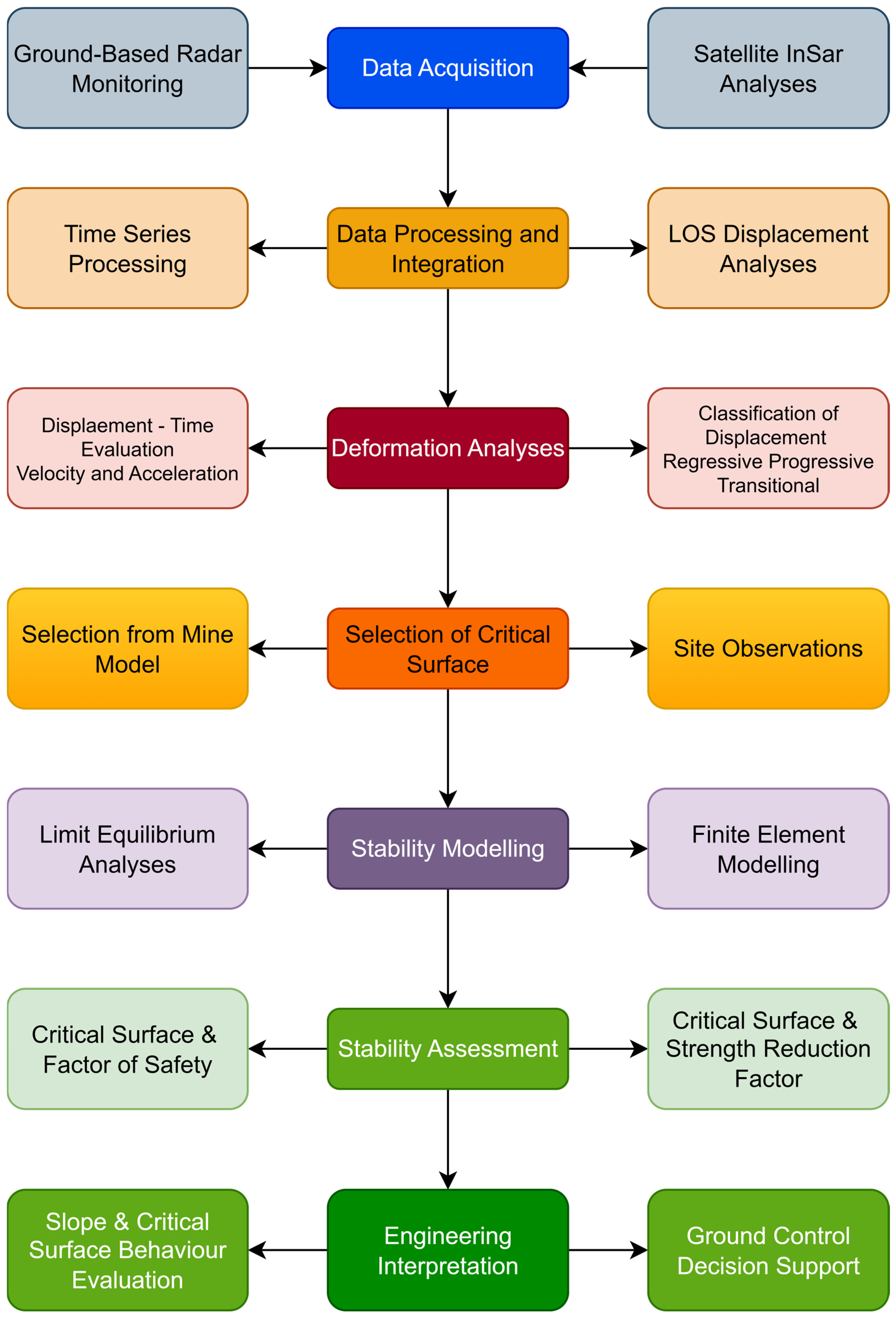
The overall workflow of the study is summarized in Figure 3. The workflow starts with the acquisition of deformation data using ground-based radar and satellite InSAR systems, followed by data processing and integration. Deformation behavior is then analyzed using displacement–time and velocity trends, allowing the identification of critical zones. These zones are subsequently evaluated through numerical modeling, and the results are interpreted in terms of slope stability and engineering decision-making. This workflow forms the basis for the results presented in the following section.
Figure 3.
Integrated methodological workflow combining ground-based radar monitoring, satellite InSAR analysis, deformation classification, and numerical modeling for slope stability assessment.
3.1. Monitoring Techniques
3.1.1. Ground-Based Radar Monitoring
Ground-based radar monitoring was carried out using an IBIS-Rover interferometric radar system installed with direct visibility to the monitored highwall sector. The system operates in the Ku-band frequency range of 17.05–17.35 GHz and measures slope displacement in the radar line-of-sight (LOS) direction from the phase difference in successively reflected signals. The main radar specifications and monitoring parameters used in this study are summarized in Table 1.
Table 1.
Summary of monitoring, InSAR processing, and numerical modeling parameters used in this study.
The radar campaign covered the active deformation period between April 2022 and November 2022. Repeated scans were acquired at 1–3 min intervals, allowing the development of cumulative displacement maps, displacement–time curves, and velocity records. The system provides LOS displacement accuracy of ±0.1 mm, with a range resolution of 0.75 m for the operating bandwidth used in the monitoring campaign. The maximum operating range of the system is 2500 m, which was sufficient to cover the monitored slope sector.
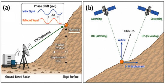
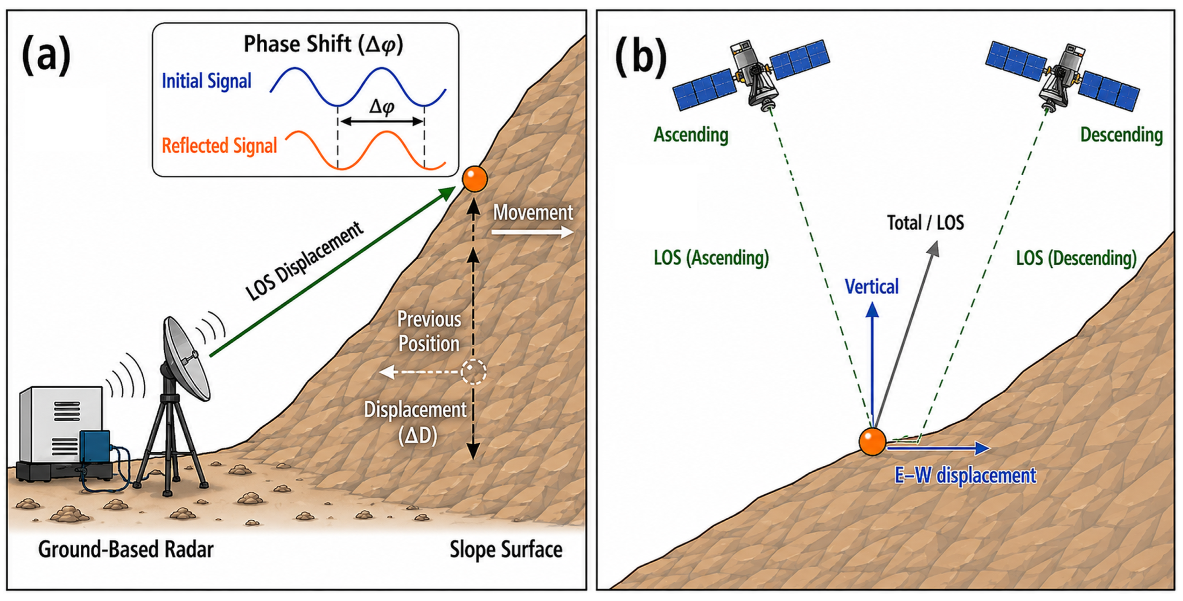
Radar data were processed using the standard radar processing workflow, including atmospheric correction and filtering of low-quality pixels with insufficient signal response. The resulting cumulative displacement maps were used to identify zones of localized deformation, while displacement and velocity time series were used to evaluate the temporal evolution of slope movement. These data provided the basis for identifying short-term acceleration phases, progressive deformation behavior, and critical zones selected for subsequent stability analyses. The measurement principle of the ground-based radar system is illustrated in Figure 4a.
Figure 4.
Schematic representation of (a) ground-based interferometric radar monitoring and (b) InSAR monitoring.
3.1.2. Satellite InSAR Processing
Satellite-based InSAR time-series analysis was used to evaluate the post-event deformation behavior of the monitored slope sector. The analysis was performed using Sentinel-1 data acquired from both ascending and descending orbit geometries. The InSAR processing was carried out using the ATLAS InSAR processing workflow of Sixense. The main processing parameters, including sensor geometry, coherence threshold, filtering approach, and DEM source, are summarized in Table 1.
The InSAR analysis covered the period between November 2022 and June 2023, following the active deformation period captured by the ground-based radar. Interferometric processing included topographic phase removal using the SRTM 30 m DEM, phase filtering using the Goldstein filter, and selection of coherent pixels based on a coherence threshold of 0.70. The resulting line-of-sight (LOS) displacement measurements were obtained separately for ascending and descending geometries.
Because InSAR measurements represent displacement along the satellite LOS direction, the ascending and descending LOS results were decomposed into vertical and east–west displacement components. This decomposition was used to identify the dominant deformation direction during the post-event period. The derived horizontal and vertical displacement time series were then interpreted together with the radar monitoring results and stability analyses. The acquisition geometry and decomposition approach are schematically shown in Figure 4b.
Ground-based interferometric radar was used to monitor slope displacements at high temporal resolution. The system measures displacement along the line-of-sight (LOS) direction by detecting phase differences in reflected electromagnetic waves, enabling millimetric accuracy. Continuous scanning allowed for the generation of displacement time-series and cumulative displacement maps, which were used to identify short-term kinematic variations associated with excavation stages and hydro-mechanical changes. The measurement principle of the radar system is illustrated in Figure 4a.
3.2. Deformation Analysis
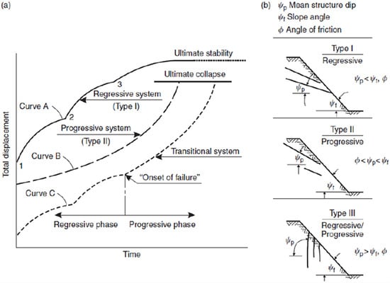
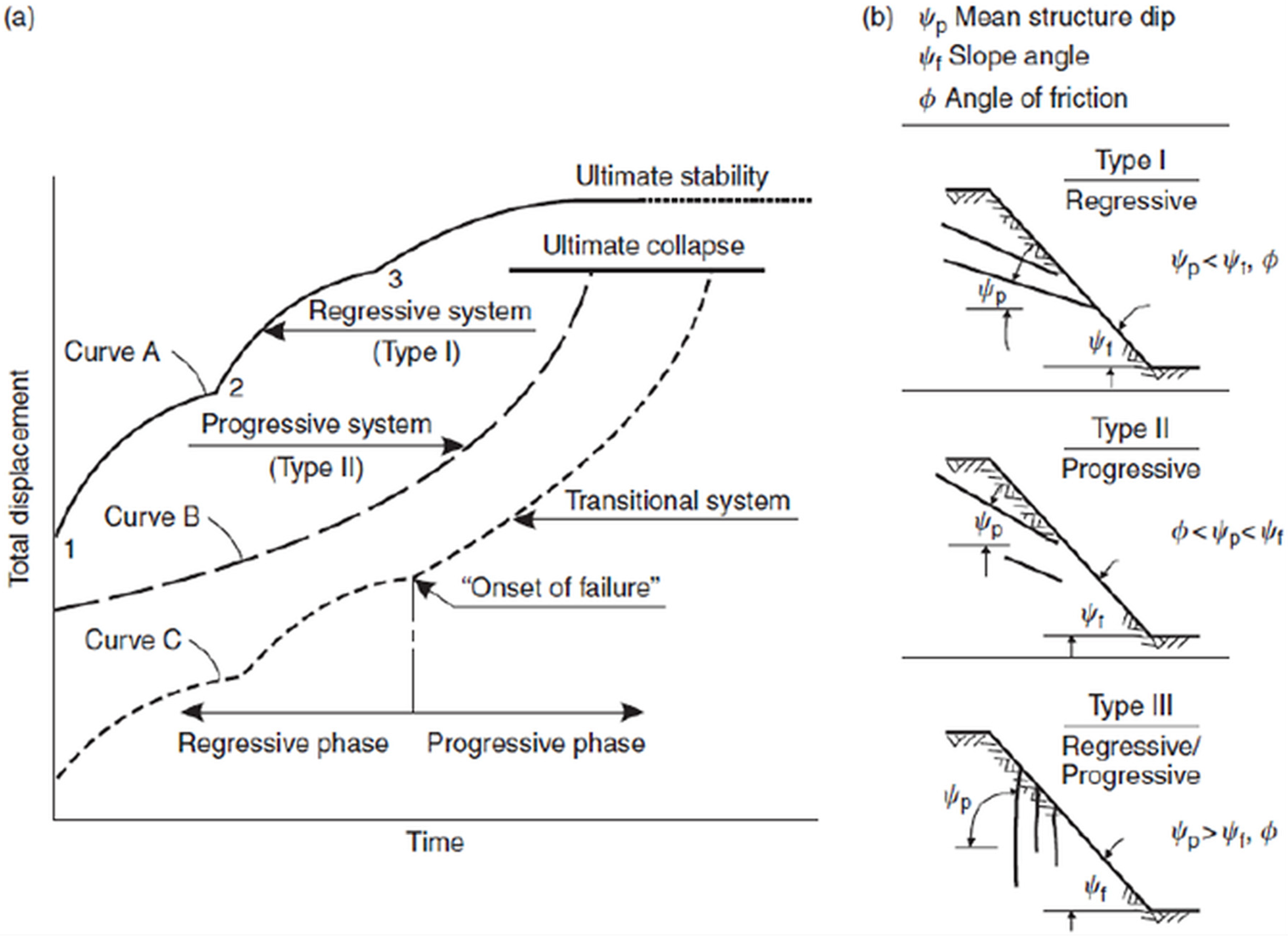
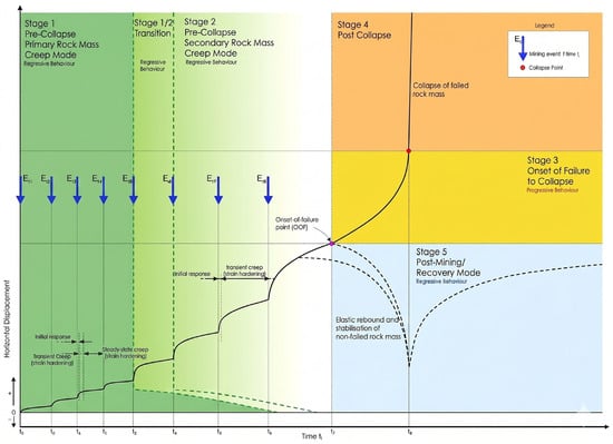
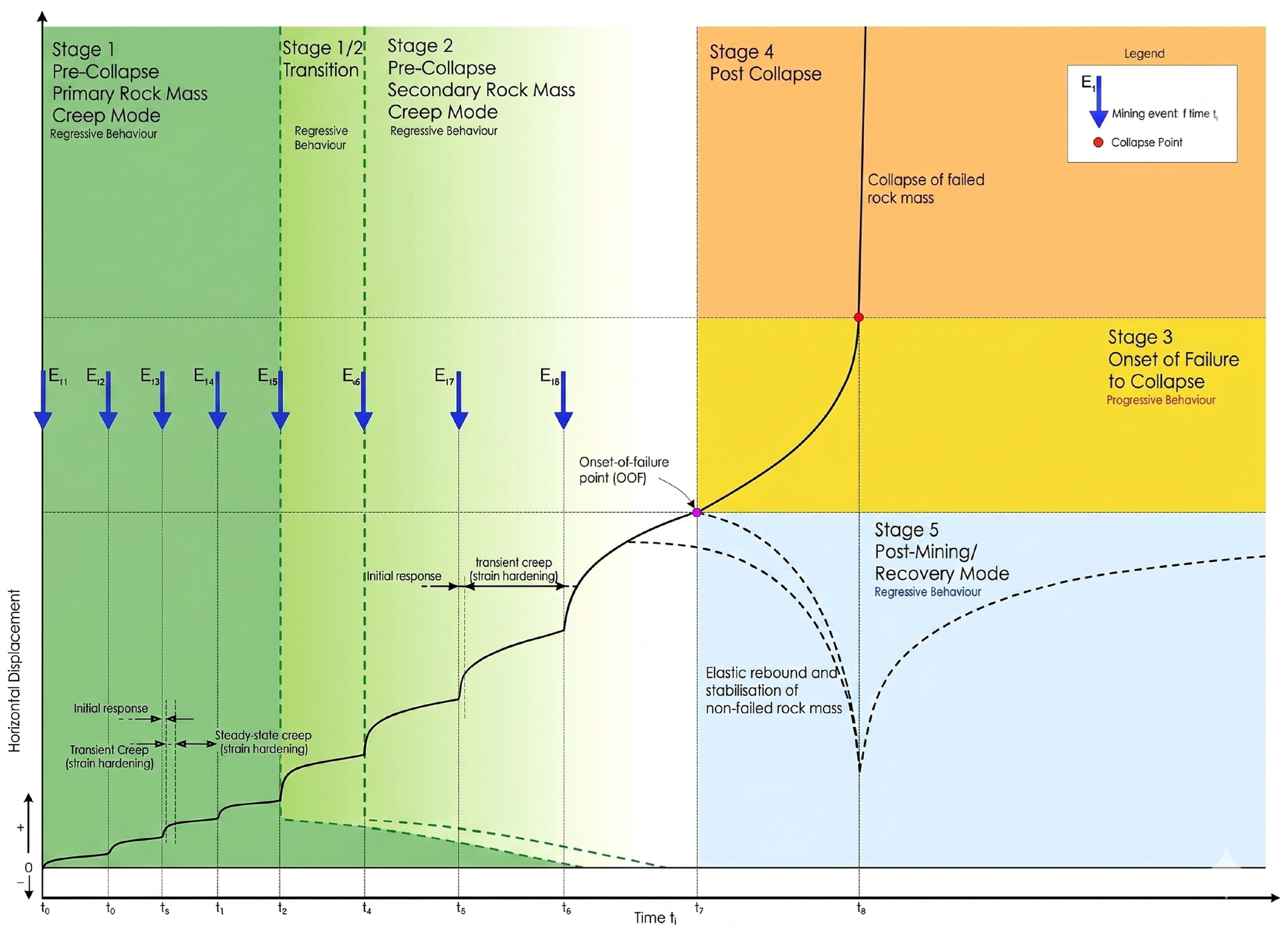
Deformation behavior was evaluated using displacement–time relationships and velocity trends derived from monitoring data. Following the approach of Broadbent and Zavodni [16], deformation responses were classified as regressive, progressive, or transitional based on the evolution of displacement rates. Regressive behavior is associated with decreasing velocity over time, while progressive behavior is characterized by sustained acceleration, indicating the potential development of instability. Transitional behavior represents intermediate conditions influenced by operational factors such as excavation stages or hydro-mechanical variations.
Velocity-based interpretation was further supported by concepts of creep and progressive failure mechanisms described in the literature [17]. In addition, deformation patterns were evaluated within an event-based framework, considering the effects of mining activities such as blasting and material removal. This approach follows the time- and event-dependent deformation model proposed in previous studies [18], allowing differentiation between temporary operational responses and mechanically significant instability. Conceptual representations of deformation behavior and velocity evolution are presented in Figure 5 and Figure 6.
Figure 5.
Conceptual displacement evolution and failure-development mechanisms in monitored rock slopes: (a) deformation trends from regressive/progressive behaviour to onset of failure and ultimate collapse; (b) slope-failure types defined by structural dip, slope angle, and friction angle relationships. Modified after [17].
Figure 6.
Conceptual time- and event-dependent deformation behavior showing regressive, progressive, and post-collapse stages. Modified after [18].
3.3. Selection of Critical Zones
Based on the combined interpretation of displacement time-series, velocity trends, and deformation classification, critical zones were identified within the slope. Particular attention was given to areas exhibiting consistent progressive or transitional behavior, as these zones are more likely to represent mechanically significant instability. The selection process also considered the spatial continuity of deformation patterns and their relationship with structural features observed in the field.
These selected zones were used as representative sections for subsequent stability analyses, ensuring that numerical modeling focused on areas with meaningful deformation signatures.
3.4. Stability Analysis
Stability analyses were carried out using both limit equilibrium and finite element approaches in order to evaluate slope behavior under different groundwater conditions and to compare observed deformation patterns with calculated stability conditions. Representative cross-sections were selected from the monitored deformation zones identified through radar and InSAR interpretation.
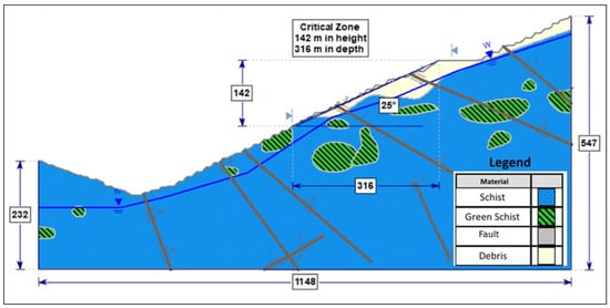
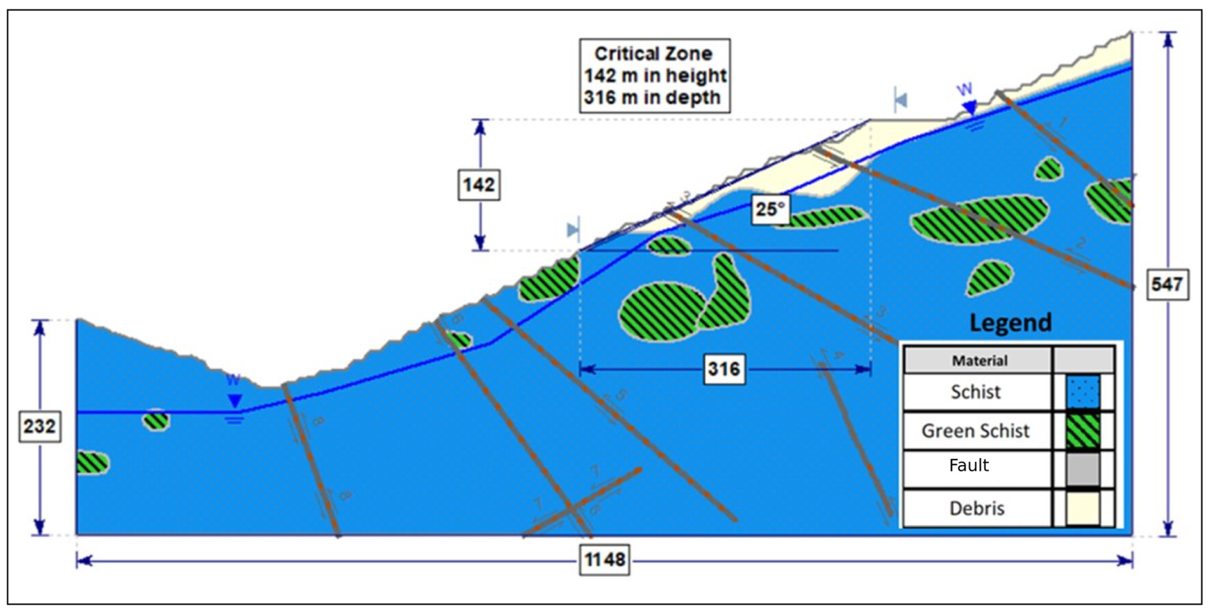
The main monitoring, InSAR processing, and numerical modeling parameters used in this study are summarized in Table 1. Limit equilibrium analyses were performed using the Bishop simplified method [19], while finite element analyses were conducted using the shear strength reduction (SRF) technique proposed by Dawson et al. [20] and later applied in finite element slope stability studies by Griffiths and Lane [21]. The finite element analyses were carried out in Rocscience RS2 (Version 11.021) using a two-dimensional plane-strain model representing the monitored slope sector. The model geometry was derived from the representative cross-section selected from the radar- and InSAR-derived deformation zone. In the shear strength reduction technique, the strength reduction factor (SRF) is defined as the factor by which the shear-strength parameters, namely cohesion and the frictional strength component represented by the internal friction angle, are progressively reduced until the finite element solution reaches a critical plastic state or cannot maintain numerical equilibrium. In this sense, SRF is conceptually related to the factor of safety used in limit equilibrium analysis, but it is obtained from the development of plastic strain and loss of numerical equilibrium rather than from force or moment equilibrium along a predefined slip surface. Therefore, the SRF values reported in this study are interpreted within the adopted two-dimensional finite element idealization and should be evaluated together with the deformation pattern and monitoring evidence. Rock mass strength parameters were defined according to the generalized Hoek–Brown failure criterion [22,23] and converted into equivalent Mohr–Coulomb parameters for numerical implementation. This GSI-based Hoek–Brown characterization was used as a conservative engineering representation of rock mass strength, and this conservatism was considered when interpreting the FoS and SRF values together with the monitoring results. The geotechnical parameters used in the analyses are summarized in Table 2, while the representative model geometry and groundwater conditions are illustrated in Figure 7. The debris layer was represented as a cohesionless granular cover material with φ = 28° and c = 0. This parameter set was used as a conservative engineering representation of the surficial debris in the stability analyses and was considered when interpreting whether the computed FoS and SRF values were controlled by the debris cover or by the underlying rock mass.
Table 2.
Geotechnical database for the lithological domains [24].
Figure 7.
A representative cross-section used in the limit equilibrium and numerical analyses [24].
The numerical models were evaluated under dry and saturated groundwater conditions in order to investigate the influence of pore pressure on slope stability. Boundary conditions were defined to restrict horizontal displacement along the lateral model boundaries and both horizontal and vertical displacement at the model base. In the finite element analyses, a uniform mesh consisting of six-noded triangular elements was used, and the mesh configuration was checked to adequately represent strain localization and displacement development near the slope face and critical deformation zones. The mesh consisted of approximately 12,000–15,000 elements. A finer mesh size of approximately 5 m was used near the slope face, structural discontinuities, and critical deformation zones, whereas a coarser mesh size of approximately 10 m was used toward the external model boundaries. The ground surface and slope face were left free to deform, while the lateral and basal restraints were assigned to prevent rigid-body movement of the model domain. Structural discontinuities were represented in the finite element model using joint elements, while weak rock zones were incorporated through the assigned material domains. This representation was adopted to account for discontinuity-controlled shear development and to evaluate its influence on strain localization and displacement patterns in the monitored slope sector. These model components were used to evaluate the influence of discontinuity-controlled shear development on the observed deformation and stability response.
In this study, the dry and saturated cases were used as bounding groundwater scenarios rather than as fully calibrated transient seepage models. The dry case represents a fully drained slope in which pore pressures are taken as zero, whereas the saturated case represents a conservative upper bound in which groundwater or rainfall-induced infiltration reduces the effective normal stress along discontinuities and weak zones. In the saturated analysis, the phreatic surface was defined at an average vertical depth of approximately 40 m below the existing topographic surface along the representative section. Pore pressures were then calculated using a hydrostatic pore-pressure distribution defined by this phreatic surface, with Hᵤ = 1. No continuous piezometric record was available for direct calibration of the pore-pressure distribution; groundwater was therefore treated as a controlling uncertainty rather than a measured input. This approach was adopted to evaluate the sensitivity of the selected slope sector to a possible pore-pressure increase rather than to reproduce a specific groundwater event.
The results obtained from stability analyses were evaluated together with radar and InSAR observations to establish a direct relationship between monitored deformation behavior and calculated stability conditions.
The comparison between monitoring and stability analysis results was evaluated by considering (i) the spatial relationship between the monitored deformation zones, critical slip surfaces, and FEM strain-localization patterns, (ii) the kinematic compatibility between the monitored displacement direction and the modeled failure geometry, and (iii) the sensitivity of FoS and SRF values to groundwater conditions.
4. Case Study and Monitoring Results
4.1. Geological and Model Framework
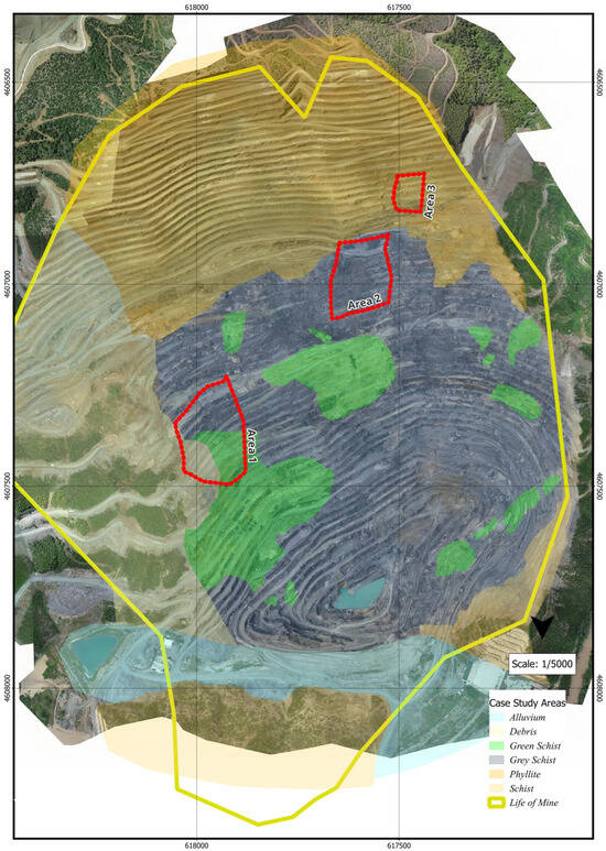
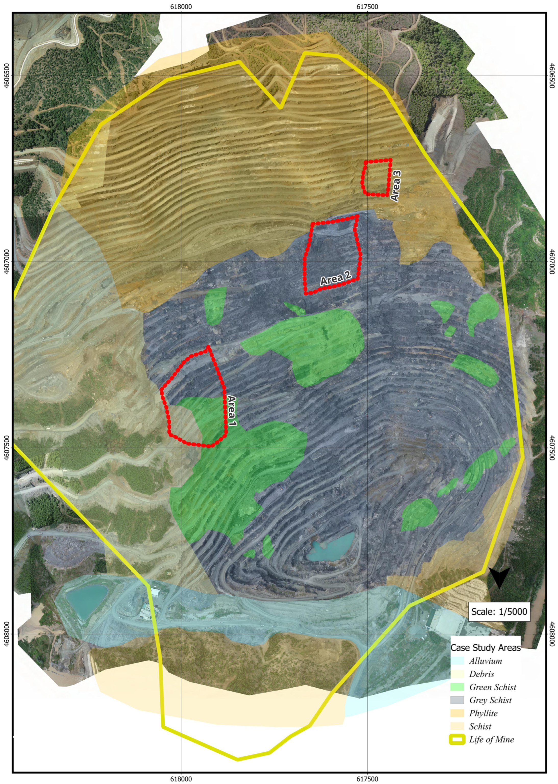
The geological setting of the open-pit mine is presented in Figure 8. The slope is primarily composed of altered volcanic and intrusive rock units characterized by variable rock mass quality and pronounced structural heterogeneity. Based on geological mapping and geotechnical investigations, these units were classified into representative lithological domains, including alluvium, debris, green schist, gray schist, phyllite, and schist, further subdivided into geotechnical domains ranging from very low to high strength. Area 1, highlighted in Figure 7, was selected as the primary study area for detailed geotechnical and stability analyses in this research.
Figure 8.
Lithological map of the open pit mine [24].
Structural discontinuities intersecting the slope play a key role in controlling deformation and potential failure mechanisms. These discontinuities were explicitly incorporated into the numerical model to represent their influence on deformation localization and shear development.
Groundwater conditions were represented by a defined water table within the model geometry. The influence of pore pressure on effective stress reduction and shear strength degradation was considered in both limit equilibrium and numerical analyses.
Overall, slope stability in the study area is governed by the combined effects of lithological variability, structural discontinuities, groundwater conditions, and slope geometry. This geological framework forms the basis for subsequent deformation monitoring and stability analyses. The geotechnical parameters used in the analyses are summarized in Table 2. The model geometry used in the limit equilibrium and numerical analyses, including slope configuration and groundwater conditions, is illustrated in Figure 7.
4.2. Radar Monitoring Results
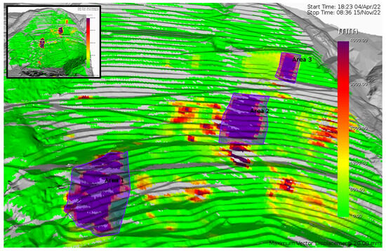
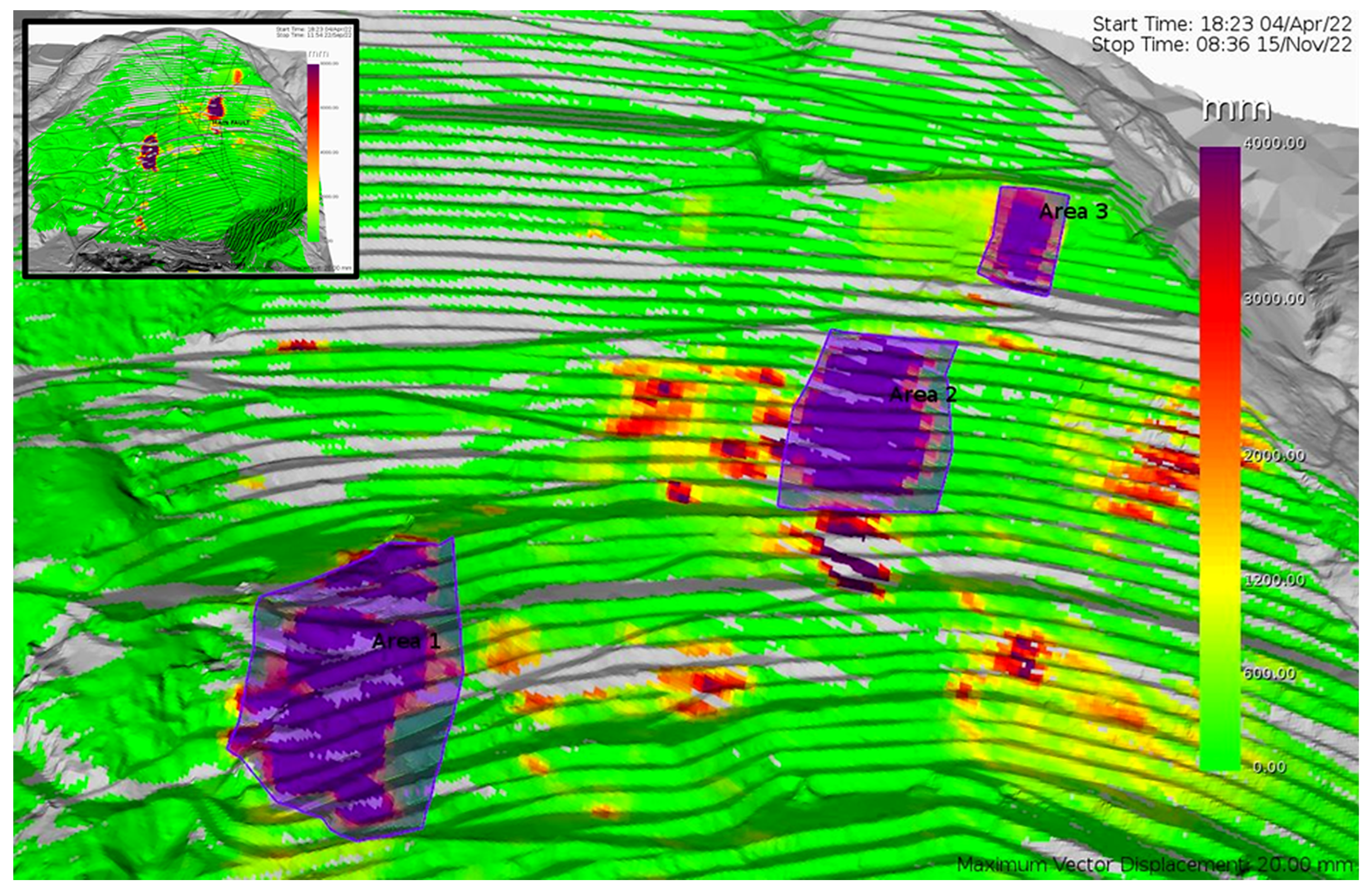
Slope displacement and velocity were continuously monitored using ground-based radar, enabling the assessment of temporal deformation evolution. The cumulative displacement map (Figure 9) indicates that deformation was concentrated within three main zones of the monitored slope.
Figure 9.
Cumulative radar displacement map. Adapted from Bulgurcu [24].
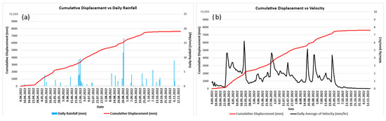
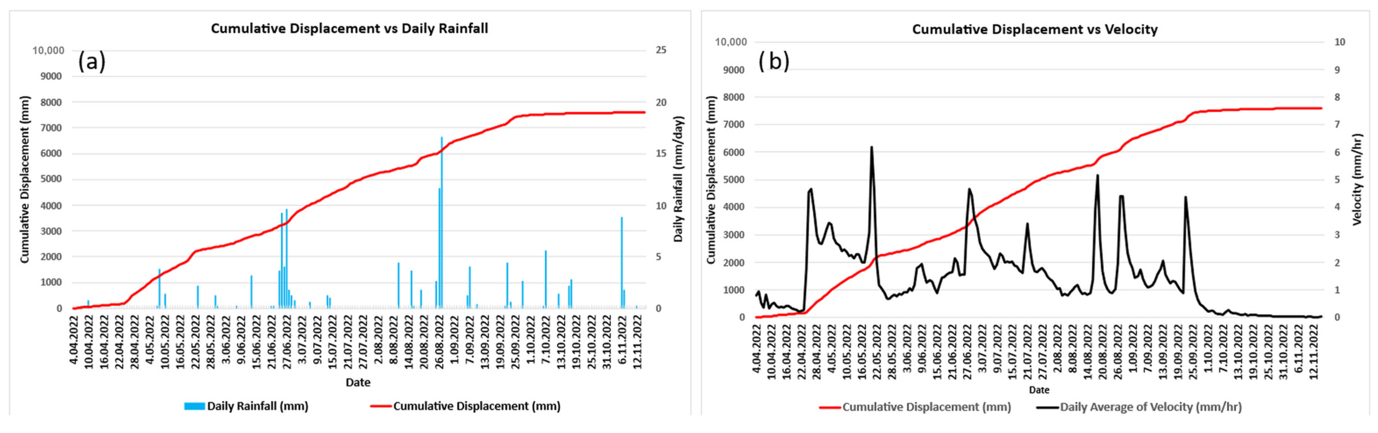
The cumulative displacement time series (Figure 10a) reveals a progressive deformation pattern characterized by distinct phases. During the early monitoring period, displacement remained low and increased gradually. From late April onwards, a more pronounced deformation trend developed, reflected by an increase in the slope of the displacement curve. Between May and early September, displacement accumulated steadily, indicating staged deformation rather than a single rapid failure event.
Figure 10.
(a) Cumulative displacement and daily rainfall, (b) radar-derived velocity [24].
The corresponding velocity record (Figure 10b) provides further insight into slope behavior. Several short-lived velocity peaks were observed, representing episodic acceleration events followed by rapid deceleration. Such acceleration–deceleration patterns are commonly associated with localized strain adjustments rather than imminent global failure [25]. Despite temporary increases in velocity, the system repeatedly returned to background levels, suggesting a non-catastrophic and progressive deformation mechanism.
Rainfall appears to have influenced short-term slope response (Figure 10a), with some displacement increments coinciding with periods of increased precipitation. This effect is interpreted as a temporary reduction in near-surface shear strength rather than a primary triggering mechanism.
After October 2022, both displacement rates and velocity values decreased significantly. The cumulative displacement curve gradually flattened, and velocity values approached background levels, indicating a progressive stabilization phase. This behavior is consistent with stress redistribution and dissipation of driving forces within the slope.
Based on the combined interpretation of displacement and velocity data, four distinct deformation phases were identified (Table 3), including initial response, progressive mobilization, episodic deformation, and final stabilization.
Table 3.
Identified deformation phases derived from radar displacement and velocity data.
4.3. InSAR Results
Post-event deformation behavior in the study area was evaluated using satellite-based InSAR observations following the ground-based radar monitoring period. The radar system monitored the active deformation stage between April 2022 and November 2022, when displacement and velocity changes were recorded at high temporal resolution. The InSAR analysis covers the subsequent period from November 2022 to June 2023 and was used to assess whether deformation continued after the radar-monitored active phase. Therefore, the two datasets should not be interpreted as fully overlapping measurements, but as complementary records representing different stages of the same deformation process: short-term active movement captured by radar and longer-term post-event deformation captured by InSAR.
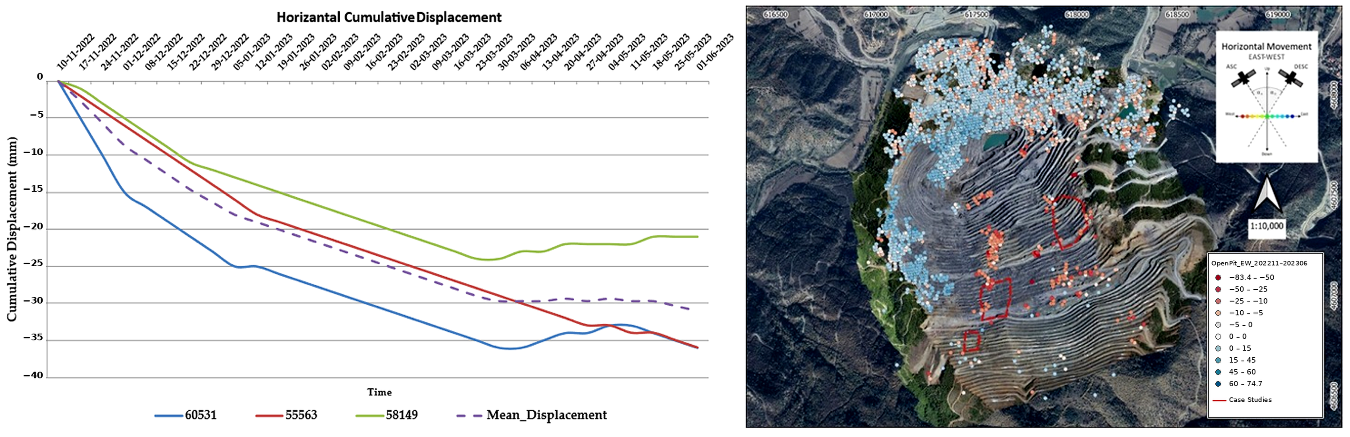
Displacement time-series derived from selected InSAR pixels within the deformation zone indicate that slope movement continued after the main deformation phase recorded by the radar system. The cumulative horizontal (east–west) displacement (Figure 11) shows a gradual increase throughout the monitoring period, reaching a maximum value of approximately 36.8 mm. The mean displacement trend further confirms the persistence of lateral movement following the initial deformation stage.
Figure 11.
Cumulative horizontal (east–west) displacement derived from selected InSAR pixels within the deformation zone between November 2022 and June 2023 [24].
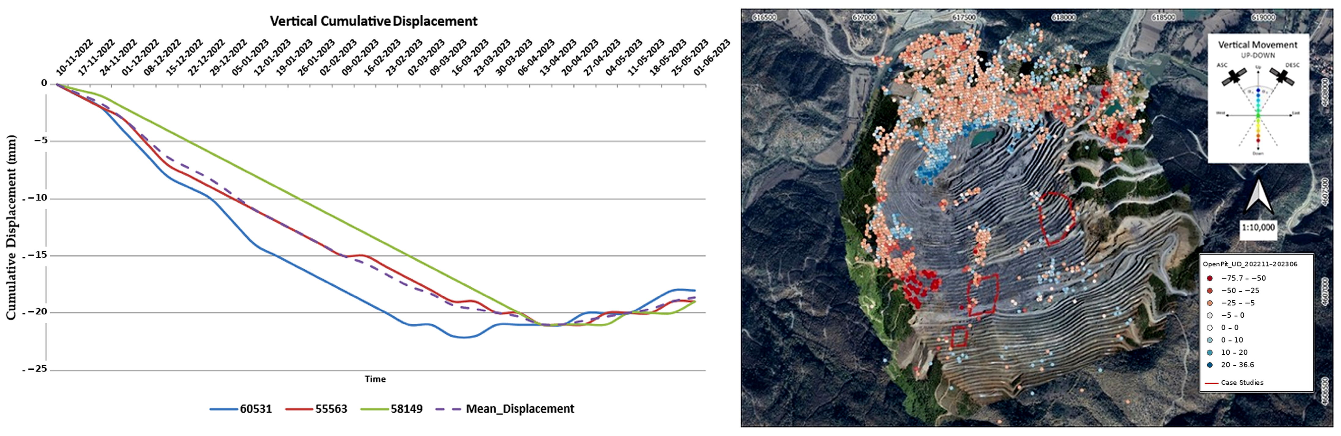
The vertical displacement component (Figure 12) exhibits a similar temporal trend but with lower magnitude, reaching approximately 21.7 mm over the same period. The relatively smaller vertical displacement compared to the horizontal component indicates that deformation is primarily controlled by lateral slope movement rather than vertical settlement.
Figure 12.
Cumulative vertical displacement derived from InSAR observations for the same monitoring period [24].
For engineering interpretation, the horizontal and vertical InSAR components were also combined as a resultant displacement vector in the east–west vertical plane. The maximum horizontal and vertical displacement components of 36.8 mm and 21.7 mm correspond to a resultant displacement magnitude of approximately 42.7 mm and a horizontal-to-vertical displacement ratio of 1.70. The resulting vector defines an apparent plunge of approximately 30° below the horizontal in this plane, indicating that the movement is dominated by lateral displacement rather than vertical settlement. The term “apparent” is used because the plunge is computed only from the east–west and vertical InSAR components; the north–south component is not recovered by the ascending–descending decomposition, and therefore the true three-dimensional plunge may differ from the value reported here. This movement direction is compatible with the interpreted slope mechanism, in which deformation is controlled by the interaction between slope geometry and the NW-dipping structural fabric.
It should be noted that InSAR measurements represent displacement in the satellite line-of-sight (LOS) direction. Therefore, the horizontal and vertical components used in this study were derived through geometric decomposition of ascending and descending datasets. The resultant vector calculated here represents displacement in the east–west vertical plane and should be interpreted as an apparent plunge within that plane, not as a complete three-dimensional displacement vector. For this reason, the InSAR-derived vector was evaluated together with radar monitoring results, slope geometry, and structural observations.
Overall, the InSAR results confirm the continuation of low-rate, progressive deformation following the main deformation phase. This behavior is consistent with gradual stress redistribution and ongoing adjustment of the slope mass, indicating a sustained but reduced deformation process in the study area.
4.4. Stability Analysis Results
4.4.1. Limit Equilibrium Method
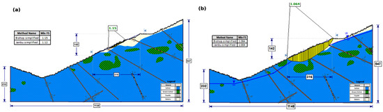
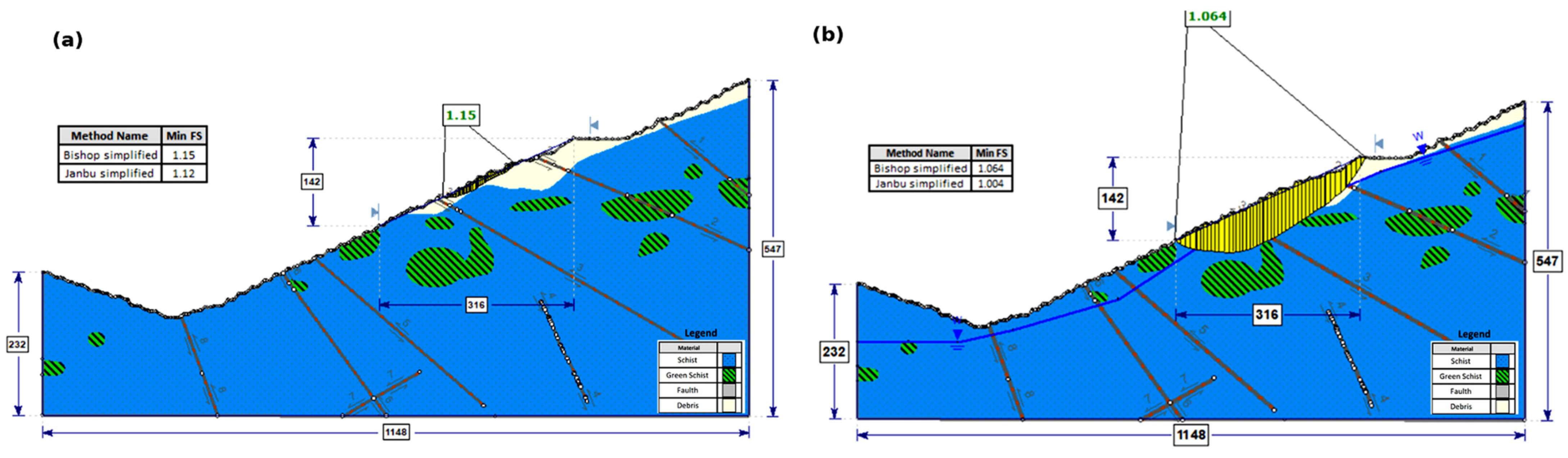
Slope stability was evaluated using limit equilibrium analyses under dry and saturated conditions. The calculated factors of safety (FoS) for the selected slope section are presented in Figure 13.
Figure 13.
Limit equilibrium stability analysis under (a) dry and (b) saturated conditions [24].
Under dry conditions, the slope is stable, with minimum FoS values of 1.15 and 1.12 obtained using the Bishop and Janbu simplified methods, respectively (Figure 13a). These results indicate that the slope maintains sufficient stability in the absence of significant groundwater influence.
When saturated conditions are considered, stability decreases notably. The minimum FoS values reduce to 1.06 (Bishop) and 1.00 (Janbu), indicating a condition close to instability (Figure 13b). The reduction in FoS to near-unity values under saturated conditions does not, by itself, imply that global failure was imminent during the monitoring period. It indicates that the static stability margin of the slope was small and that the slope response was sensitive to pore-pressure changes. This interpretation is consistent with the radar and InSAR records, which show progressive and episodic deformation rather than uncontrolled acceleration toward a continuous global failure surface. This reduction is attributed to the increase in pore pressure, which lowers effective stress and shear strength within the slope mass. This reduction should be interpreted as a sensitivity response to a possible pore-pressure increase within the slope rather than as the reconstruction of a measured groundwater state. The decrease in FoS under saturated conditions indicates that even a moderate loss of effective stress along discontinuities or weak rock zones can move the slope toward a near-limit-equilibrium state.
Overall, the limit equilibrium results demonstrate that the results of the stability analyses do not satisfy commonly accepted stability criteria (FoS ≥ 1.30) and indicate high sensitivity to groundwater conditions. The observed reduction in FoS under saturated conditions is consistent with the progressive deformation patterns identified from radar monitoring data.
4.4.2. Finite Element Method
Finite element analyses were performed using the shear strength reduction approach to investigate the deformation pattern and possible failure mechanism of the selected slope section under saturated groundwater conditions. In this approach, the shear-strength parameters are progressively reduced until the model reaches a critical plastic state or numerical non-convergence. The resulting SRF value was therefore used as a numerical stability indicator associated with the development of critical strain localization, rather than as a direct replacement for the limit equilibrium FoS.
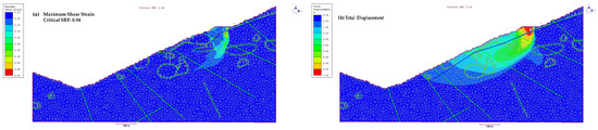
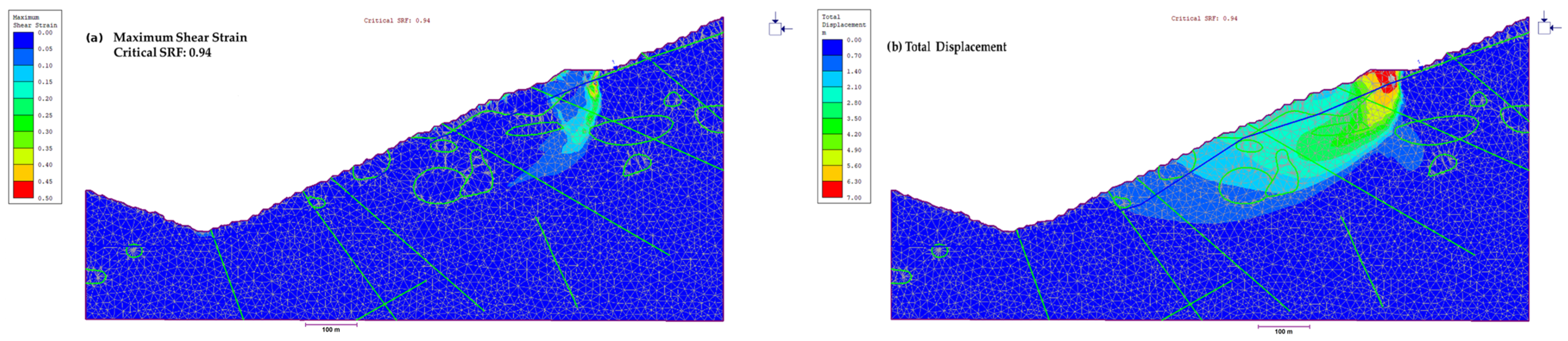
Under saturated conditions, the critical SRF value is 0.94, indicating that the modeled section has a low numerical stability margin under the adopted two-dimensional plane-strain conditions. The maximum shear strain contours show that deformation localizes near the upper slope sector and propagates along structurally controlled weak zones within the underlying rock mass. The total displacement pattern is consistent with this localization and indicates concentration of numerical deformation in the same critical slope domain.
The sub-unity SRF value should not be interpreted as evidence that a completed global collapse occurred during the monitoring period. Rather, it indicates that the modeled section is close to a critical deformation state under the adopted numerical assumptions and that localized yielding can develop before an unconstrained global slide is observed in the field. This interpretation is consistent with the monitoring record, which shows progressive and episodic deformation of a few tens of millimeters rather than sudden catastrophic failure.
Figure 14 is arranged to distinguish between the stability index and the deformation outputs obtained from the finite element analysis. Figure 14a shows the maximum shear strain distribution at the critical SRF stage under saturated conditions. Figure 14b presents the corresponding total displacement pattern. The displacement output is included to illustrate the direction and concentration of numerical deformation, and the displacement magnitudes should not be interpreted as measured field displacements.
Figure 14.
Finite element analysis results for the selected slope section under saturated groundwater conditions: (a) maximum shear strain distribution at critical SRF = 0.94 and (b) corresponding total displacement pattern [24].
The deformation patterns obtained from finite element analyses are in agreement with radar monitoring observations, showing that slope movement initiates near the crest and progresses along structurally controlled zones. Accordingly, Figure 14b is used to support the interpretation of deformation direction and localization, rather than to quantify field displacement magnitude.
Overall, the finite element results support the interpretation that slope deformation is controlled by structural discontinuities and is strongly influenced by groundwater conditions.
4.4.3. Quantitative Comparison of Monitoring and Stability Results
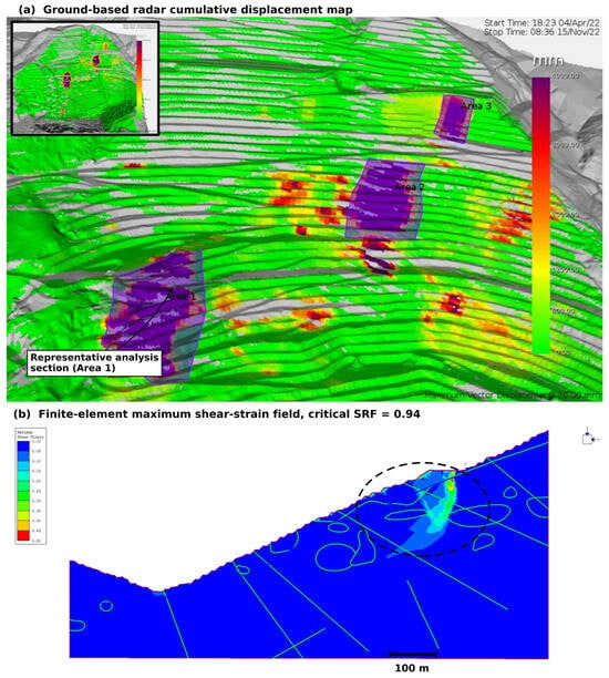
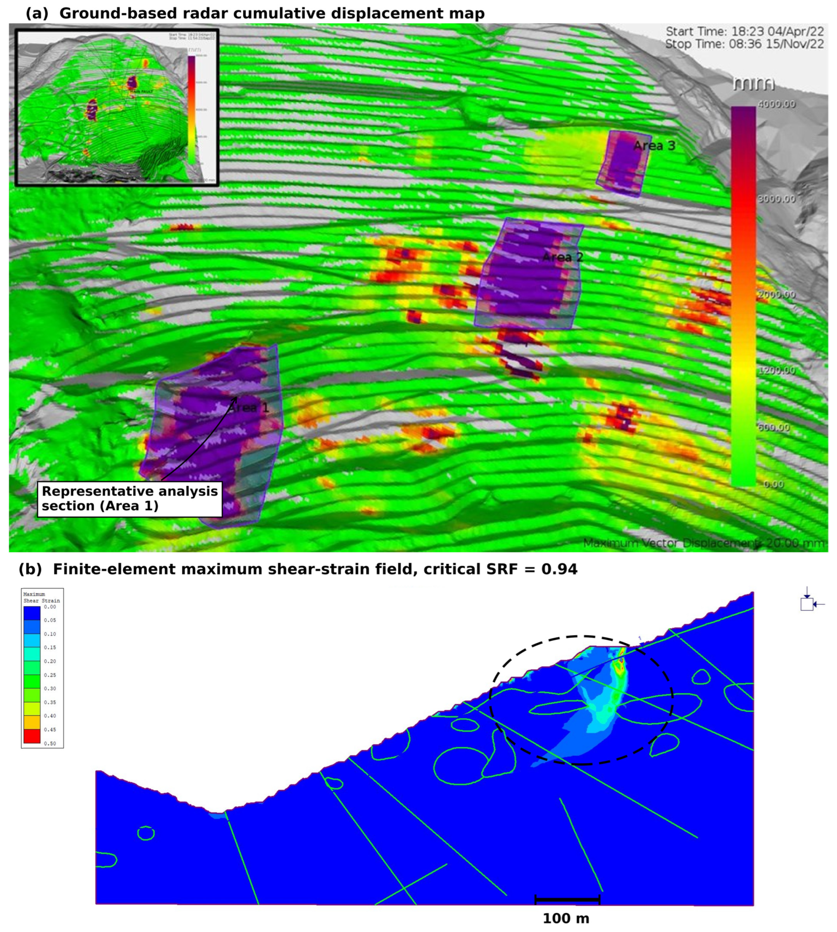
To establish a clearer relationship between the monitoring observations and the stability analyses, the monitored deformation zones and the modeled instability patterns were compared on the representative analysis section shown in Figure 15, and the main quantitative indicators are summarized in Table 4. Radar monitoring indicated that deformation was concentrated within three discrete zones (Areas 1–3) rather than being uniformly distributed across the pit wall. Similarly, the FEM results showed that maximum shear strain and total displacement were concentrated near the upper slope sector and crest region.
Figure 15.
Comparison between monitored deformation and modeled instability response. (a) Ground-based radar cumulative displacement map showing the main monitored deformation zones (Areas 1–3); (b) FEM maximum shear-strain distribution along the representative analysis section at critical SRF conditions. Both the monitored deformation concentration and the modeled strain-localization zone develop within the upper slope sector and crest region, indicating spatial agreement between the monitoring observations and the numerical stability analyses.
Table 4.
Quantitative comparison between monitoring observations and stability analysis results.
Projection of the monitored deformation domain onto the representative section indicates that the monitored displacement concentration and the FEM strain-localization band occupy the same critical slope sector, with a centroid offset of less than 40 m along the section. This agreement provides a direct spatial relationship between the observed deformation and the modeled instability response.
The InSAR results indicate cumulative horizontal and vertical displacement components of approximately 36.8 mm and 21.7 mm, respectively. When these components are evaluated together, they define a resultant displacement magnitude of approximately 42.7 mm in the east–west vertical plane, with a horizontal-to-vertical displacement ratio of 1.70 and an apparent plunge of approximately 30° below the horizontal. This vectorial interpretation shows that the deformation is dominated by lateral movement and is compatible with the interpreted sliding geometry and NW-dipping structural fabric controlling the slope.
The influence of groundwater conditions was also quantified through the stability analyses. Under saturated conditions, the Bishop and Janbu FoS values decreased from 1.15 and 1.12 to 1.06 and 1.00, corresponding to reductions of approximately 8–10%. The FEM analysis under saturated conditions yielded a critical SRF of 0.94. This value is consistent with the near-limit-equilibrium condition indicated by the saturated LEM results and supports the interpretation of a low stability margin in the same slope sector. The maximum shear strain pattern shows localization within the upper slope sector and underlying rock mass, which agrees with the monitored deformation domain and the interpreted structurally controlled movement mechanism.
Although the FoS and SRF values differ numerically, the two approaches do not contradict each other because they describe different aspects of slope response. The FoS values obtained from the limit equilibrium analyses describe the balance between resisting and driving forces along assumed slip surfaces, whereas the SRF values obtained from the finite element analyses reflect the reduction level at which critical strain localization develops in the numerical model. The near-unity FoS values and the sub-unity FEM-based SRF value therefore provide complementary indicators of a low stability margin in the selected slope sector. This is consistent with the observed field behavior, where deformation was progressive and episodic but did not develop into a global collapse during the monitoring period.
4.4.4. Internal Consistency Checks
Although the study is based on a single open-pit slope and no independent monitoring dataset from a second site was available, the interpretation was checked through three internal consistency steps within the available case-study data.
The first consistency check is between the two monitoring datasets. Ground-based radar and satellite InSAR are based on different sensors, acquisition geometries, processing chains, and observation periods. The radar data captured the active deformation phase at high temporal resolution, whereas the InSAR data showed that low-rate deformation continued during the subsequent monitoring period. The agreement between these two datasets in terms of the location of the deforming sector and the persistence of movement indicates that the observed displacement pattern is a genuine slope response rather than an artifact of a single monitoring technique.
The second consistency check is between the two stability analysis approaches. The limit equilibrium and finite element analyses are based on different assumptions and calculation procedures, yet both identify a low stability margin in the same critical slope sector. The near-unity FoS values under saturated conditions and the sub-unity critical SRF value obtained from the finite element analysis indicate a slope condition between marginal limit-equilibrium stability and localized progressive deformation. This agreement supports the interpretation that the monitored slope was close to a critical deformation state, even though a global collapse did not occur during the observation period.
The third consistency check is between monitoring and modeling. The monitored deformation zones and the FEM strain-localization pattern are concentrated within the same upper slope sector. In addition, the InSAR-derived displacement vector is kinematically compatible with the interpreted sliding geometry, and the groundwater sensitivity inferred from the monitoring record is consistent with the reduction in FoS under saturated conditions and the sub-unity FEM-based SRF value. These checks do not replace validation against an independent site or a documented historical failure event, but they provide a constrained and internally consistent interpretation of the deformation mechanism within the available dataset.
The absence of a catastrophic failure should also be considered in this context. This study does not represent a post-failure back-analysis of a collapsed slope. Instead, it addresses the pre-failure or progressive-deformation stage, where monitoring data and stability analyses can still be used to support ground control decisions before global failure develops. The observed behavior, characterized by progressive and episodic displacement rather than sudden collapse, is therefore consistent with the purpose of the proposed workflow.
5. Discussion
The combined use of ground-based radar and satellite-based InSAR provides a more complete view of slope deformation by capturing both short-term and long-term behavior. Radar monitoring is particularly effective in detecting rapid changes in displacement, including short-lived acceleration phases and fluctuations in velocity during active periods. In contrast, InSAR data reveal a more gradual evolution of deformation over extended time intervals, highlighting the persistence of low-rate movements following the main deformation phase. Similar integration of radar and InSAR datasets has been shown to significantly improve the interpretation of slope behavior in open-pit environments [26].
When evaluated as consecutive monitoring records, these datasets indicate that the deformation process did not terminate after the radar-monitored active period, but continued at a reduced rate during the subsequent InSAR observation period. The short-term variations observed in radar measurements can therefore be interpreted as part of a longer-term deformation trend that is more clearly captured by InSAR. This consistency between independent monitoring techniques supports the interpretation that slope movement is progressive and sustained rather than associated with a single rapid failure event, which is consistent with time-dependent deformation behavior described in previous studies [25]. The contribution of the proposed workflow should also be considered in relation to recent developments in remote sensing and data-driven slope assessment. Previous InSAR-based studies have shown that satellite observations can detect slope deformation trends, identify precursory displacement behavior, and support deformation prediction [9,10]. Feasibility-oriented studies have emphasized that InSAR results must be interpreted with attention to terrain geometry, vegetation cover, and deformation gradients [11]. In parallel, data-driven stability studies have shown that safety factors and potential failure surfaces can be estimated from slope geometry and strength parameters [12]. Compared with these studies, the present work does not aim to advance one individual monitoring or modeling technique. Instead, it links monitoring-derived deformation evidence with FoS- and SRF-based stability indicators within an operational ground control workflow. This distinction is important for open-pit mining, where measured deformation must be translated into engineering meaning before it can support slope management decisions.
The relationship between deformation behavior and stability conditions is evident when monitoring results are compared with analytical findings. The observed displacement and velocity patterns indicate staged and progressive deformation, which is consistent with limit equilibrium results showing factors of safety close to unity under saturated conditions. In addition, finite element analyses reveal localized strain development without the formation of a well-defined global failure surface. These observations suggest that the slope operates close to a limit equilibrium state, where deformation is governed by gradual stress redistribution rather than sudden collapse. Similar stability evaluations in open-pit copper mine slopes have also emphasized the importance of geological and geomechanical conditions in controlling slope performance [27]. More generally, deformation mechanisms controlled by structural discontinuities have been widely reported in rock slope studies [28].
As summarized in Table 4, the relationship between deformation behavior and stability conditions becomes clearer when the monitoring indicators are evaluated together with the calculated FoS and SRF values. Radar monitoring showed spatially localized and progressive deformation, while InSAR measurements confirmed continued post-event movement with a dominant horizontal component. The same slope sector yielded FoS values close to unity under saturated conditions and a FEM-based critical SRF value of 0.94. This agreement indicates that the observed deformation was not only a surface-monitoring anomaly but also reflected a mechanically weak slope condition reproduced by the stability models. The combined results therefore support the interpretation that the slope operates close to a limit equilibrium state, with deformation governed by groundwater-sensitive, structurally controlled shear zones.
The near-unity FoS values obtained from the limit-equilibrium analyses and the sub-unity SRF value obtained from the FEM analysis reflect the low stability margin of the modeled section under saturated conditions. The two approaches describe different aspects of the slope response: the FoS values represent force or moment equilibrium along assumed slip surfaces, whereas the SRF value reflects the onset of critical strain localization in the finite element model. The monitored field behavior, characterized by progressive and episodic displacement without global collapse, is consistent with a marginally stable slope condition between these analytical responses. The SRF values lower than unity should therefore be interpreted within the numerical framework of the shear strength reduction analysis. They indicate that, under the adopted two-dimensional model assumptions, the selected section has a very low stability margin and is susceptible to progressive strain localization. This does not mean that a global collapse occurred in the field. Instead, it is consistent with a slope that is close to a critical condition and accommodates deformation through localized, structurally controlled movement. The monitoring record supports this interpretation, as the slope showed progressive and episodic displacement without evidence of sudden global failure.
The role of parameter back-analysis should also be considered within the intended use of the proposed workflow. The aim of the workflow is not to recalibrate rock mass strength parameters after each monitored deformation episode, but to use the calculated FoS and SRF values together with radar and InSAR observations as operational indicators of reduced stability margin. In this context, a sub-unity SRF or a near-unity FoS should not be treated simply as a numerical inconsistency to be removed by adjusting the input parameters. Instead, when such values coincide with monitored deformation, they should trigger closer inspection of the affected sector and reassessment of design or operational measures, such as bench geometry, drainage conditions, excavation sequence, or access control. Full retrospective back-analysis remains useful where a documented failure surface, reliable pore-pressure information, and sufficient deformation constraints are available. However, routine recalibration during ongoing operation may lead to non-unique parameter sets and may reduce the conservative warning function of the stability analysis, particularly in structurally controlled rock slopes where groundwater assumptions, model dimensionality, and discontinuity representation strongly influence the computed stability factors.
The role of the surficial debris layer was also considered in this interpretation. The debris unit was assigned conservative cohesionless parameters to represent weak near-surface cover material. This choice may influence shallow deformation tendencies and the calculated stability margin; however, the stability response of the modeled section is not governed by the debris cover alone. In the limit-equilibrium analyses, the critical slip surfaces under both dry and saturated conditions develop through the rock mass rather than being confined to the debris layer. Similarly, the finite element analysis under saturated conditions shows that the maximum shear strain band is concentrated in the underlying schist domain in the upper-crest region. The conservative debris parameters therefore represent the surficial cover above the controlling mechanism and do not, by themselves, govern the computed FoS or SRF values. Where debris or other low-strength surficial materials form thicker or laterally more continuous units, site-specific characterization of these materials would be required.
The near-unity FoS values obtained under saturated conditions should be interpreted together with the monitored deformation pattern. In limit equilibrium analysis, FoS is a static ratio between resisting and driving forces along an assumed failure surface. It indicates how close the slope is to limiting equilibrium under the modeled conditions, but it does not describe the rate, style, or timing of deformation in the field. A FoS value close to unity therefore does not necessarily mean that sudden global collapse must occur during the same observation period. It indicates a small stability margin and a slope condition that is sensitive to additional loading, pore-pressure increase, or geometric modification.
This interpretation is consistent with the monitoring record. Radar measurements showed staged displacement accumulation, short-lived velocity peaks, and subsequent deceleration, while InSAR observations indicated continued low-rate movement after the active deformation period. The deformation was therefore accommodated progressively through localized yielding and strain redistribution rather than through rapid development of a continuous, uncontrolled failure surface. Several factors may have contributed to this behavior. The analyses represent a two-dimensional plane-strain section of a three-dimensional slope, and lateral confinement or out-of-plane resistance in the field may contribute additional restraint that is not fully represented in the model. In addition, structurally controlled rock slopes often deform by progressive mobilization of discontinuity-controlled segments rather than by simultaneous movement along the entire potential slip surface. The saturated condition used in the analyses also represents a conservative bounding scenario rather than a continuously sustained groundwater state.
Within this framework, the decrease in FoS from 1.15 to 1.12 under dry conditions to 1.06–1.00 under saturated conditions represents an approximately 8–10% reduction in the static stability margin. The monitoring data show that this reduced margin was expressed as progressive deformation of a few tens of millimeters in the same critical slope sector identified by the stability analyses. The near-unity FoS values therefore indicate a slope operating close to limiting equilibrium, while the observed progressive deformation represents the field expression of that marginal condition rather than evidence of an immediate global collapse.
Groundwater appears to be one of the main factors controlling this sensitivity. The saturated analyses represent a conservative bound rather than a calibrated groundwater model, but they show how pore-pressure increase may affect the slope when water enters discontinuities, fractured zones, or weak lithological contacts. Under such conditions, effective normal stress decreases and shear resistance along potential movement surfaces is reduced. This explains why the FoS values approach unity under saturated conditions and why the FEM analysis indicates localized strain development at a sub-unity critical SRF value.
This interpretation is also supported by the monitoring record. Several short-term displacement increments and velocity peaks broadly coincide with rainfall periods shown in Figure 10a, suggesting that rainfall infiltration may have contributed to transient pore-pressure increases along near-surface discontinuities. The available data do not allow a fully calibrated hydrogeological back-analysis; nevertheless, the temporal association between rainfall and episodic deformation is consistent with groundwater-sensitive slope behavior.
In operational terms, the results indicate that drainage condition, rainfall infiltration, and local groundwater accumulation should be treated as key uncertainty factors in the ground control process. For this reason, the proposed workflow should be used together with routine inspection of drainage performance and, where possible, pore-pressure monitoring in critical slope sectors.
From an operational perspective, the results highlight the importance of integrating monitoring systems with stability analyses in open-pit mine management. The combined interpretation of radar, InSAR, and stability modeling enables the identification of critical zones, the assessment of stability conditions, and the evaluation of slope conditions and potential adjustments where required. This integrated approach supports proactive decision-making by allowing potentially unstable areas to be re-evaluated before critical conditions are reached. Consequently, continuous monitoring and iterative stability assessment emerge as essential components for maintaining safe and sustainable mining operations.
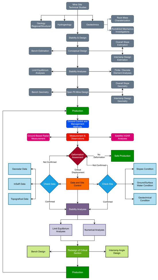
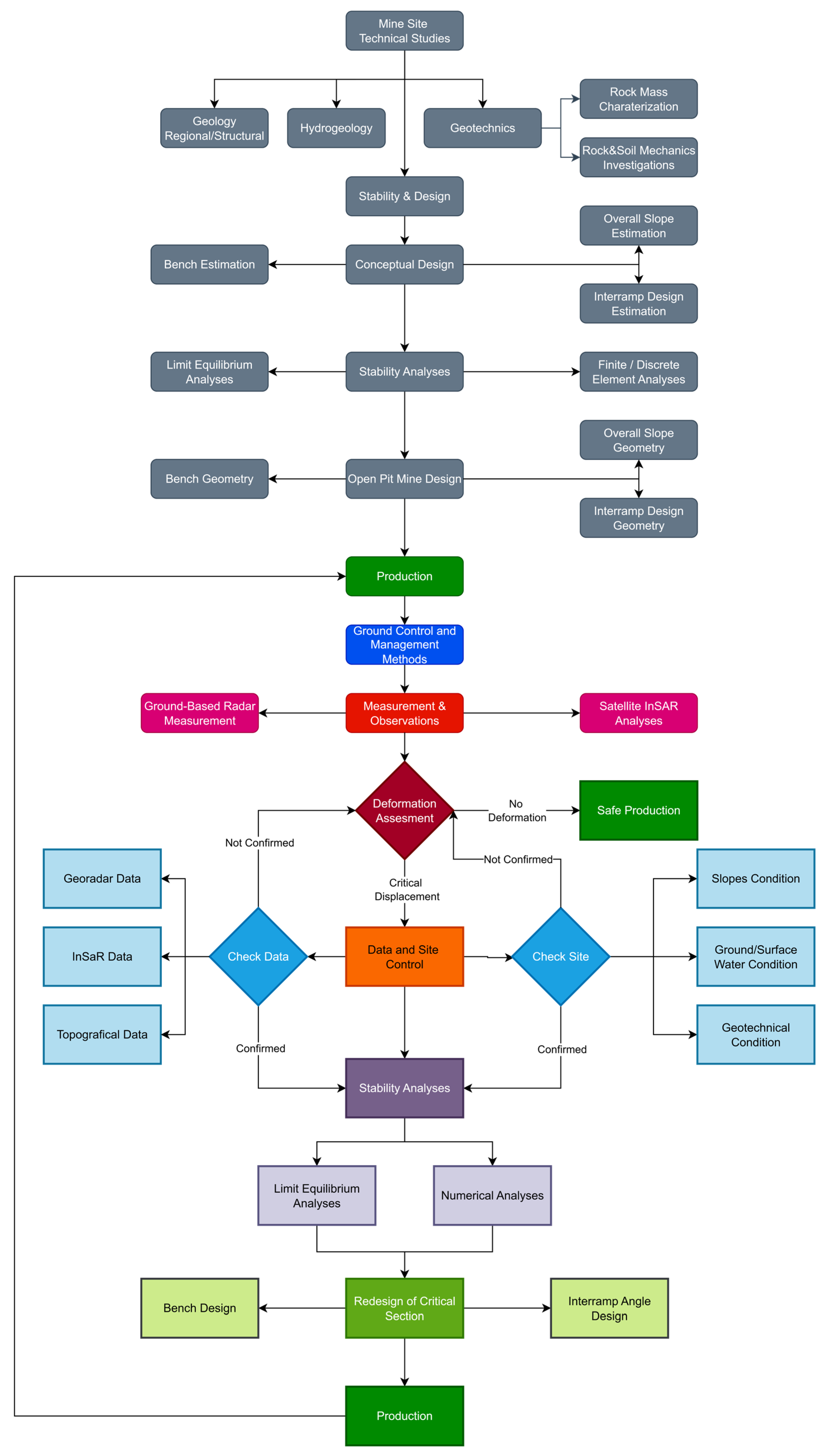
In conventional open-pit slope design, stability assessment is primarily based on a predefined geotechnical model and design parameters, followed by implementation during production [29]. However, the findings of this study highlight the need to extend this approach by incorporating continuous monitoring and retrospective stability evaluation throughout the operational phase. This integrated framework, illustrated in Figure 16, enables adaptive management of slope stability conditions and supports sustainable open-pit mining practices. This approach provides a direct link between observed deformation and quantified stability conditions, offering a practical framework for decision-making in open-pit slope management.
Figure 16.
Proposed integrated ground control workflow combining monitoring data and stability analysis for sustainable open-pit slope management.
The case-study nature of this work defines both its strength and its boundary of application. The study is based on one open-pit mine and on one documented progressive deformation episode within that mine. Therefore, the displacement magnitudes, FoS values, SRF values, groundwater sensitivity, and deformation thresholds reported here should be regarded as site- and event-specific. They should not be transferred directly to other open-pit mines, or even to other sectors of the same mine, without recalibration against local geological, structural, hydrogeological, and monitoring conditions.
The study is deliberately framed as a monitoring-based ground control interpretation rather than a universal prediction model. Its purpose is to demonstrate how a documented deformation episode can be evaluated by linking radar and InSAR observations with FoS- and SRF-based stability indicators during ongoing mining operations. In this sense, the transferable contribution is not the numerical values themselves, but the interpretation sequence: detecting localized deformation from monitoring data, checking whether the deformation is mechanically consistent with stability analyses, and using the combined evidence to support slope reassessment during operation.
A historical global failure event was not available for direct back-analysis, and the monitored deformation did not evolve into a catastrophic collapse during the observation period. For this reason, the study should be regarded as a pre-failure or progressive-deformation case rather than a post-failure back-analysis case. This distinction is important because the proposed workflow is intended to support decision-making before deformation develops into uncontrolled failure. Within this scope, the interpretation is supported by consistency between independent monitoring platforms, independent stability analysis methods, and the spatial relationship between monitored deformation and modeled strain localization. Future applications to additional open-pit sites, different deformation mechanisms, and cases with documented historical failures would be needed to test the wider transferability of the workflow.
6. Conclusions
This study examines slope behavior in an open-pit mining environment by combining ground-based radar monitoring, satellite-based InSAR observations, and numerical stability analyses. The results show that deformation developed progressively over time rather than as a single failure event, with movement concentrated in specific zones of the slope. Radar data captured short-term variations and episodic acceleration phases, while InSAR observations indicate that low-rate deformation continued after the main movement period, with cumulative horizontal and vertical displacements reaching approximately 36.8 mm and 21.7 mm, respectively.
The numerical analyses are consistent with the monitoring results. Limit equilibrium analyses show that the slope approaches critical conditions, with factors of safety decreasing from 1.15 to 1.12 under dry conditions to 1.06–1.00 under saturated conditions. Finite element results further support this behavior, with a critical SRF value of 0.94 under saturated conditions and deformation localizing along structurally controlled zones. These findings indicate that slope response is strongly influenced by groundwater conditions and structural discontinuities. Under saturated conditions, the slope operates close to limiting equilibrium, where the reduced static stability margin is expressed not as sudden global failure but as progressive, structurally controlled deformation that can be detected and tracked through integrated radar and InSAR monitoring.
The main outcome of this study is the combined interpretation of deformation monitoring and stability analysis. The results show that deformation patterns derived from radar and InSAR can be directly related to stability conditions, allowing a more consistent assessment of slope performance under operational conditions. This makes it possible to identify critical zones and to better understand the evolution of slope behavior during mining.
The proposed workflow is intended as a practical framework for integrating monitoring data with stability evaluation in open-pit operations. Within this framework, the workflow does not rely on routine recalibration of strength parameters against each monitoring record. Instead, low FoS or SRF values are treated as quantitative warning indicators that should lead to intensified monitoring and review of design, drainage, and operational measures in the affected slope sector. While no explicit slope redesign is carried out in this study, the approach provides a basis for such decisions by linking observed deformation with engineering stability indicators. In this way, it supports the reassessment of slope conditions during operation and contributes to safer and more sustainable ground control practices. This study demonstrates the application of the proposed workflow using one open-pit mine and one documented progressive deformation episode. The numerical values obtained in the case study are site- and event-specific; however, the interpretation sequence can be adapted to other open-pit operations where monitoring data and stability analyses are available. Future work should apply the workflow to additional mine sites, different deformation mechanisms, and, where post-failure datasets exist, retrospective back-analysis of historical slope failures.
Author Contributions
Conceptualization, C.A.O. and M.T.B.; methodology, M.T.B.; software, M.T.B.; validation, M.T.B. and C.A.O.; formal analysis, M.T.B.; investigation, M.T.B.; data curation, M.T.B.; writing—original draft preparation, M.T.B.; writing—review and editing, C.A.O.; visualization, M.T.B.; supervision, C.A.O. All authors have read and agreed to the published version of the manuscript.
Funding
This research received no external funding.
Institutional Review Board Statement
Not applicable. This study did not involve humans or animals.
Informed Consent Statement
Not applicable.
Data Availability Statement
The data presented in this study are available upon reasonable request from the corresponding author. The data are not publicly available due to confidentiality of the case study site.
Acknowledgments
This study was derived from the MSc thesis entitled “Ground Control Principles Based on Retrospective Analyses from Actual Site Conditions in Open Pit Mining” conducted at the Graduate School of Science, Engineering and Technology of Istanbul Technical University.
Conflicts of Interest
The authors declare no conflicts of interest.
Abbreviations
The following abbreviations are used in this manuscript:
| FEM | Finite Element Method |
| FoS | Factor of Safety |
| GSI | Geological Strength Index |
| InSAR | Interferometric Synthetic Aperture Radar |
| LEM | Limit Equilibrium Method |
| LOS | Line of Sight |
| SRF | Strength Reduction Factor |
| TDR | Time Domain Reflectometry |
References
- Zhang, C.; Clement, A.; Kodama, J.-I.; Sainoki, A.; Fujii, Y.; Fukuda, D.; Wang, S. Effect of the Connectivity of Weak Rock Zones on the Mining-Induced Deformation of Rock Slopes in an Open-Pit Mine. Sustainability 2024, 16, 5974. [Google Scholar] [CrossRef] [Scilit]
- Kadakci Koca, T. The Effect of Geometrical Features of Release Surfaces on the Stability of Tectonically Disturbed Deep Rock Slopes in an Albite Open Pit Mine. Sustainability 2023, 15, 1425. [Google Scholar] [CrossRef] [Scilit]
- Saik, P.; Lozynskyi, V.; Saik, K.; Petlovanyi, M.; Malanchuk, Y. Substantiation of the Direction for Mining Operations That Develop under Conditions of Shear Processes Caused by Hydrostatic Pressure Influence when Mining the Zavalivskyi Graphite Deposit. Sustainability 2023, 15, 15690. [Google Scholar] [CrossRef] [Scilit]
- Pavloudakis, F.; Roumpos, C.; Spanidis, P.-M. Sustainable Mining and Processing of Mineral Resources. Sustainability 2024, 16, 8393. [Google Scholar] [CrossRef] [Scilit]
- Shi, S.; Guo, Z.; Ding, P.; Tao, Y.; Mao, H.; Jiao, Z. Failure Mechanism and Stability Control Technology of Slope during Open-Pit Combing Underground Extraction: A Case Study from Shanxi Province of China. Sustainability 2022, 14, 8939. [Google Scholar] [CrossRef] [Scilit]
- Le Roux, R.; Sepehri, M.; Khaksar, S.; Murray, I. Slope Stability Monitoring Methods and Technologies for Open-Pit Mining: A Systematic Review. Mining 2025, 5, 32. [Google Scholar] [CrossRef] [Scilit]
- Enkhbold, B.; Ikeda, H.; Toriya, H.; Adachi, T. A Comprehensive Numerical Modeling Study for Parameter Optimization and Slope Stability Analysis in the Baganuur Lignite Coal Mine. Mining 2023, 3, 755–772. [Google Scholar] [CrossRef] [Scilit]
- Benndorf, J.; Merkel, N.; John, A. Data-Supported Prediction of Surface Settlement Behavior on Opencast Mine Dumps Using Satellite-Based Radar Interferometry Observations. Mining 2024, 4, 926–942. [Google Scholar] [CrossRef] [Scilit]
- Deng, Z.; Wang, W.; Luo, Y.; Zhang, S.; Xu, L.; Su, Q. Slope Deformation Monitoring and Prediction Based on InSAR and Deep Learning Model. Results Eng. 2025, 28, 107113. [Google Scholar] [CrossRef] [Scilit]
- Carlà, T.; Intrieri, E.; Raspini, F.; Bardi, F.; Farina, P.; Ferretti, A.; Colombo, D.; Novali, F.; Casagli, N. Perspectives on the Prediction of Catastrophic Slope Failures from Satellite InSAR. Sci. Rep. 2019, 9, 14137. [Google Scholar] [CrossRef] [Scilit]
- Chen, Y.; Dai, K.; Chang, L.; Deng, J.; Zhuo, G.; Dong, X.; Liu, X.; Shao, Y. The Pre-Processing InSAR Feasibility Assessment Method for Wide-Area Slope Displacement Monitoring. Int. J. Appl. Earth Obs. Geoinf. 2025, 136, 104336. [Google Scholar] [CrossRef] [Scilit]
- Won, M.; Sadiq, S.; Wang, J.; Gao, Y. Predicting Slope Stability Potential Failure Surface Using Machine Learning Algorithms. Arab. J. Geosci. 2025, 18, 24. [Google Scholar] [CrossRef] [Scilit]
- Okay, A.I.; Sunal, G.; Sherlock, S.; Altıner, D.; Tüysüz, O.; Kylander-Clark, A.R.C.; Aygül, M. Early Cretaceous Sedimentation and Orogeny on the Active Margin of Eurasia: Southern Central Pontides, Turkey. Tectonics 2013, 32, 1247–1271. [Google Scholar] [CrossRef] [Scilit]
- Günay, K.; Dönmez, C.; Oyan, V.; Yıldırım, N.; Çiftçi, E.; Yıldız, H.; Özkümüş, S. Geology and Geochemistry of Sediment-Hosted Hanönü Massive Sulfide Deposit (Kastamonu–Turkey). Ore Geol. Rev. 2018, 101, 434–456. [Google Scholar] [CrossRef] [Scilit]
- General Directorate of Mineral Research and Exploration (MTA). 1:100,000 Scale Geological Map Series of the Central Pontides; MTA: Ankara, Türkiye, 2023. [Google Scholar]
- Broadbent, C.D.; Zavodni, Z.M. Influence of Rock Structure on Stability. In Stability in Surface Mining; Society of Mining Engineers: Denver, CO, USA, 1982; Chapter 2; Volume 3. [Google Scholar]
- Sullivan, T.D. Hydromechanical Coupling and Pit Slope Movements. In Proceedings of the International Symposium on Rock Slope Stability in Open Pit Mining and Civil Engineering (Slope07), Perth, Australia, 12–14 September 2007; Australian Centre for Geomechanics: Perth, Australia, 2007; pp. 3–43. [Google Scholar]
- Mercer, K.G. Investigation into the Time Dependent Deformation Behaviour and Failure Mechanisms of Unsupported Rock Slopes Based on the Interpretation of Observed Deformation Behaviour. Ph.D. Thesis, University of the Witwatersrand, Johannesburg, South Africa, 2006. [Google Scholar]
- Bishop, A.W. The Use of the Slip Circle in the Stability Analysis of Slopes. Géotechnique 1955, 5, 7–17. [Google Scholar] [CrossRef] [Scilit]
- Dawson, E.M.; Roth, W.H.; Drescher, A. Slope Stability Analysis by Strength Reduction. Géotechnique 1999, 49, 835–840. [Google Scholar] [CrossRef] [Scilit]
- Griffiths, D.V.; Lane, P.A. Slope Stability Analysis by Finite Elements. Géotechnique 1999, 49, 387–403. [Google Scholar] [CrossRef] [Scilit]
- Hoek, E.; Brown, E.T. Empirical Strength Criterion for Rock Masses. J. Geotech. Eng. Div. 1980, 106, 1013–1035. [Google Scholar] [CrossRef] [Scilit]
- Hoek, E.; Carranza-Torres, C.; Corkum, B. Hoek–Brown Failure Criterion—2002 Edition. In Proceedings of the 5th North American Rock Mechanics Symposium (NARMS), Toronto, ON, Canada, 7–10 July 2002; pp. 267–273. [Google Scholar]
- Bulgurcu, M.T. Ground Control Principles Based on Retrospective Analyses from Actual Site Conditions in Open Pit Mining. Master’s Thesis, Istanbul Technical University, Istanbul, Türkiye, 2024. [Google Scholar]
- Zavodni, Z.M. Time-Dependent Movement of Open Pit Slopes. In Slope Stability in Surface Mining; Hustrulid, W.A., McCarter, M.K., Van Zyl, D.J.A., Eds.; Society for Mining, Metallurgy, and Exploration: Littleton, CO, USA, 2001; pp. 81–87. [Google Scholar]
- Carlà, T.; Farina, P.; Intrieri, E.; Ketizmen, H.; Casagli, N. Integration of Ground-Based Radar and Satellite InSAR Data for the Analysis of an Unexpected Slope Failure in an Open-Pit Mine. Eng. Geol. 2018, 235, 39–52. [Google Scholar] [CrossRef] [Scilit]
- Lashgari, M.; Öztürk, C.A. Slope Failure and Stability Investigations for an Open Pit Copper Mine in Turkey. Environ. Earth Sci. 2022, 81, 5. [Google Scholar] [CrossRef] [Scilit]
- Stead, D.; Wolter, A. A Critical Review of Rock Slope Failure Mechanisms: The Importance of Structural Geology. J. Struct. Geol. 2015, 74, 1–23. [Google Scholar] [CrossRef] [Scilit]
- Read, J.; Stacey, P. Guidelines for Open Pit Slope Design; CSIRO Publishing: Collingwood, Australia, 2009; ISBN 978-0-643-09469-7. [Google Scholar]

Disclaimer/Publisher’s Note: The statements, opinions and data contained in all publications are solely those of the individual author(s) and contributor(s) and not of MDPI and/or the editor(s). MDPI and/or the editor(s) disclaim responsibility for any injury to people or property resulting from any ideas, methods, instructions or products referred to in the content. |
© 2026 by the authors. Licensee MDPI, Basel, Switzerland. This article is an open access article distributed under the terms and conditions of the Creative Commons Attribution (CC BY) license.