


Abstract
The rapid integration of renewable energy sources has accelerated the adoption of DC microgrids as an effective platform for flexible and reliable power generation and management. However, conventional droop-based control suffers from inherent limitations, particularly voltage deviations at the DC bus, which compromise stability, power-sharing accuracy, and overall system performance. To address these challenges, this paper presents a distributed secondary control framework for a standalone PV battery-based DC microgrid that achieves bus voltage regulation, precise power distribution, and state-of-charge (SoC) balancing across multiple energy storage units (ESUs). At the primary level, an adaptive mechanism is introduced that dynamically adjusts droop coefficients in response to the real-time SoC of each ESU, promoting balanced utilization of storage resources. At the secondary level, the strategy leverages limited peer-to-peer communication to exchange only aggregate power information, thereby enabling accurate load sharing while preserving scalability and plug-and-play capability. The control architecture further incorporates voltage and current error compensation, with parameters tuned using a Whale Optimization Algorithm to enhance dynamic response. Validation is carried out through a real-time simulation environment developed in MATLAB/Simulink R2024b and executed on a SpeedgoatTM platform. The results demonstrate robust SoC equalization, improved bus voltage stability, and reliable cooperative coordination, positioning the scheme as a practical solution for next-generation DC microgrids.
1. Introduction
In recent years, the global energy landscape has undergone a significant transformation, marked by a growing shift toward clean and renewable energy sources. This trend has been largely driven by increasing awareness of the environmental consequences of climate change, including rising global temperatures, extreme weather events, and ecosystem disruptions [1,2]. Additionally, the finite nature of fossil fuel reserves and the geopolitical and economic risks associated with their continued extraction and use have further accelerated the transition [3]. As a result, governments, industries, and communities worldwide are investing heavily in sustainable energy alternatives such as solar, wind, hydro, and bioenergy, aiming to reduce greenhouse gas emissions, enhance energy security, and promote long-term environmental stewardship. With the ongoing advancement of distributed generation technologies, microgrids have become a prominent solution and have attracted widespread research interest [4]. DC microgrids have emerged as a compelling alternative to traditional AC microgrids, offering distinct advantages in terms of control simplicity, system reliability, and operational efficiency [5]. One of the key benefits of DC microgrids lies in their ability to bypass many of the challenges inherent in AC systems. Unlike AC microgrids, DC systems do not require complex mechanisms for frequency synchronization or suffer from harmonic distortion issues, nor do they involve reactive power management, which often complicates AC grid operation and control [5,6].
Moreover, the growing integration of modern electronic loads, energy storage systems (ESSs), and renewable energy sources (RESs)—all of which inherently operate on DC—has further strengthened the case for DC microgrids. These components align naturally with DC infrastructure, reducing the need for power conversions and enhancing overall system performance. As a result, DC microgrids are increasingly being adopted in a wide range of applications, from residential and commercial energy systems to data centers and electric vehicle charging networks, highlighting their expanding role in the future of decentralized power systems [7].
The inherently intermittent and variable characteristics of renewable energy sources, such as solar and wind, pose significant challenges to the stability and reliability of power systems. To address these challenges, energy storage units (ESUs) play a critical role in smoothing out power output fluctuations associated with these renewable sources [8,9]. By temporarily storing excess energy during periods of high generation and supplying it during periods of low generation, ESUs help to ensure a continuous and stable power supply to connected loads. This capability is especially important for maintaining the reliable and steady operation of DC microgrids, where fluctuations can directly impact system performance and power quality [10].
However, a single ESU often has limited rated capacity, which may be insufficient to meet the dynamic power demands or buffering requirements in practical applications. As a result, multiple ESUs are typically connected in parallel within the system to collectively provide the necessary energy storage capacity and enhance overall system flexibility and resilience [9,11]. Consequently, ensuring accurate and balanced power distribution among multiple energy storage units (ESUs) is a critical aspect of maintaining optimal performance and reliability in DC microgrids [12]. Effective power sharing prevents overloading of individual units and extends the overall lifespan of the energy storage system. To address this challenge, numerous studies in the literature [13,14,15] have proposed the use of droop control techniques. Droop control is widely favored for its simplicity and decentralized nature—it allows for autonomous operation of ESUs without the need for a communication network, thus reducing system complexity and improving scalability. Despite these advantages, droop control is not without limitations. One of its fundamental drawbacks lies in the inherent trade-off it creates between accurate power sharing and voltage regulation. As droop control adjusts output power based on deviations in terminal voltage, achieving precise load sharing often comes at the cost of voltage deviations across the system. This compromise can hinder voltage recovery performance, particularly under dynamic load conditions or during transient events [16,17]. As a result, while droop control remains a practical and low-cost solution, its limitations highlight the need for more advanced or hybrid control strategies that can achieve both accurate power distribution and robust voltage regulation in modern DC microgrids.
In response to the limitations of primary droop control, recent advancements in control strategies have focused on the integration of secondary control mechanisms to achieve improved system performance. Specifically, secondary control has been introduced as a means to simultaneously ensure accurate power sharing among energy storage units and maintain stable bus voltage within DC microgrids [18]. This layered approach builds upon the decentralized nature of primary droop control by adding a higher-level correction mechanism that compensates for its inherent shortcomings. To further enhance the precision of current sharing and system robustness, researchers have explored the application of active disturbance rejection control (ADRC) within the secondary control framework [19,20]. However, the implementation of ADRC in [19] relies heavily on global system information, such as the total load demand or the states of all distributed units. This reliance necessitates extensive communication infrastructure, which can increase system complexity, cost, and vulnerability to communication failures. To address this issue, the approach proposed in [20] introduces an optimized communication strategy aimed at reducing the dependency on global information. By employing localized data exchange and coordination among neighboring units, this method significantly lowers communication overhead. Nonetheless, despite its reduced reliance on global data, the overall control architecture remains intricate. A cooperative secondary control strategy was proposed in [21], aiming to enhance system performance by coordinating the actions of distributed energy storage units. This approach regulates the DC bus voltage using a voltage observer; at the same time, it improves the accuracy of current distribution through the implementation of a dedicated current regulator. The work in [22] introduces a distributed cooperative control strategy that incorporates SoC correction factors into the droop mechanism for dynamic adjustment. By exchanging only local voltage and power information with neighboring ESUs, the method achieves SoC balancing, accurate power sharing, and stable bus voltage regulation while alleviating communication overhead. However, although communication demands are reduced, the framework still requires careful parameter tuning and may encounter scalability limitations as the microgrid size increases. In a related effort, the study in [23] introduced a novel concept of a “virtual voltage drop,” where droop coefficients and the impedance of interconnecting lines are leveraged to emulate voltage drops; this virtual behavior facilitates voltage recovery and power sharing. However, despite their innovative designs, both methods share a critical limitation—they do not adequately account for the influence of external disturbances, such as load fluctuations, measurement noise, or system parameter uncertainties. This oversight can compromise the reliability and robustness of the control systems when deployed in real-world environments, where such disturbances are inevitable. Utilizing a cascaded control framework, a distributed secondary control technique was introduced in [24] to improve the overall robustness of the system. This approach specifically targets the suppression of communication-related disturbances. Building on the need to address communication challenges, the study in [25] focused on the effects of communication delays within DC microgrid systems. To mitigate these delays, a proportional–integral consensus algorithm was employed, facilitating coordinated control among distributed units. This technique offers a distributed optimal control solution.
The control strategies discussed above primarily concentrate on ensuring accurate power distribution and stable bus voltage regulation. While these are critical objectives, they do not fully address an equally important aspect in DC microgrids with multiple parallel energy storage units (ESUs): the dynamic balancing of the state of charge (SoC) across all units. Maintaining SoC balance is essential for achieving equitable power distribution among the ESUs over time, especially under varying load and generation conditions [26]. Moreover, effective SoC management plays a pivotal role in safeguarding the health and longevity of storage batteries. Without proper SoC balancing, some units may become overcharged or excessively discharged, leading to accelerated degradation and potential failure. Over time, this imbalance can compromise the overall performance and reliability of the microgrid [27]. To tackle the challenge of SoC imbalance, a communication-free stabilizing technique was put forth in [28]. This method introduces a novel approach by linking the droop coefficient to the state of charge (SoC) through a power-law relationship: specifically, defining the droop coefficient as a function of the SoC raised to the nth power. Using the appropriate selection of the exponent n, the strategy enables dynamic adjustment of power contributions from each ESU, thereby promoting SoC balancing across the system. Although the method provides a degree of SoC balancing through optimal parameter tuning, due to the absence of information exchange, its overall effectiveness is constrained in scenarios where more coordinated and responsive control is needed. In [29], the concept of “virtual current” was introduced, which integrates both its SoC and the actual current of the battery pack to inform control decisions. The technique contributes to improved SoC management and voltage regulation, but its effectiveness in achieving accurate and equitable current sharing across all units remains constrained. In [11], a dynamic droop control strategy was developed by formulating a functional relationship between the droop coefficient and SoC. This approach enables real-time adjustment of the droop coefficient based on each unit’s SoC, thereby promoting effective SoC balancing among multiple energy storage units. However, a key limitation of this approach lies in its reliance on the global average SoC across all ESUs. To compute and utilize this average, continuous communication and data exchange between units are required. As the number of ESUs increases, the communication overhead and system complexity grow significantly. This scalability issue can hinder practical implementation, particularly in large-scale or communication-constrained microgrid environments. In [30], the control technique achieved its objectives by leveraging information exchanged between neighboring ESUs and introducing an SoC convergence factor to accelerate the balancing of SoC levels. This distributed approach enabled faster SoC equalization without relying on global system data. However, while the method effectively promotes rapid SoC convergence, it falls short in maintaining stable bus voltage.
Stability remains one of the most critical challenges in DC microgrids due to their low inertia, the presence of constant-power loads (CPLs), and the tight coupling introduced by droop-controlled converters. Unlike AC systems—where stability criteria are well established—DC grids often exhibit fast voltage dynamics that can become unstable when multiple power electronic interfaces interact through resistive lines. Several studies have highlighted that improper droop coefficient selection, converter–load interactions, and the presence of distributed storage can lead to voltage oscillations or loss of power-sharing accuracy. Ref. [31] provided a rigorous nonlinear Lyapunov-based stability analysis showing that droop-based charge sharing must account for converter dynamics to guarantee global stability. Similarly, ref. [32] demonstrated that augmented droop and MPPT control in PV-based DC microgrids require careful tuning to ensure stable equilibrium transitions between modes. These findings underline the importance of integrating stability-oriented control design into DC microgrid architectures, motivating the development of robust secondary and adaptive control strategies such as those proposed in this research.
To address these issues, this article proposes a coordinated distributed control technique tailored for DC microgrids incorporating multiple ESSs. The proposed approach is designed to achieve both stable bus voltage recovery and accurate power allocation among storage units, ensuring reliable and efficient microgrid operation. The main contributions of this work can be summarized as follows:
- A novel SoC-adaptive droop control strategy is introduced, where each ESU autonomously adjusts its droop coefficient as a function of its real-time state of charge. This enables capacity-aware and SoC-sensitive power sharing, preventing over-discharge of weaker units and ensuring fair energy utilization across the microgrid.
- A lightweight distributed secondary control framework is developed to restore the DC bus voltage and achieve coordinated power balancing using only neighbor-to-neighbor communication. The design avoids any centralized computation and eliminates single points of failure.
- A formal stability and convergence analysis is presented for the combined adaptive droop and distributed secondary control loops. Using Lyapunov techniques and Laplacian eigenvalue properties, we prove boundedness of the adaptive droop law, convergence of the secondary consensus dynamics, and asymptotic regulation of the DC bus voltage.
- A whale optimization algorithm (WOA) is employed to tune the consensus weighting parameter, improving transient response and ensuring faster agreement among ESUs without requiring extensive manual tuning.
- The complete control architecture is validated through detailed simulations and real-time experiments on a Speedgoat target, demonstrating faster voltage recovery, lower SoC divergence, and more accurate dynamic power sharing when compared with conventional droop-based approaches.
The remainder of this paper is structured as follows: Section 2 provides an overview of the DC microgrid system. Section 3 presents the proposed secondary collaborative control strategy for multiple ESUs, emphasizing voltage regulation, accurate power distribution and state-of-charge balancing. Section 4 describes the real-time simulation studies conducted to assess the effectiveness of the proposed approach. Finally, Section 5 concludes the paper with a summary of key findings and insights.
2. System Architecture
2.1. Overview of DC Microgrid
The typical architecture of a standalone DC microgrid, which consists of distributed energy resources (DERs), such as photovoltaic (PV) systems, alongside battery ESSs and various loads, including resistive and constant power types, is depicted in Figure 1. PV typically operates under a maximum power point tracking (MPPT) control mode, ensuring optimal energy extraction from renewable sources. ESS plays a critical role in maintaining the stability and reliability of the microgrid. Its primary functions include regulating the bus voltage and ensuring real-time power balance within the system. This is achieved through controlled charging and discharging operations, which are dynamically adjusted based on fluctuations in load demand and generation units. Furthermore, due to the power limitations of individual energy storage converters, a single unit is often insufficient to meet the overall energy requirements of the system. To address this constraint, multiple ESS converters are commonly connected in parallel, increasing overall energy handling capacity and providing enhanced system scalability, flexibility, and redundancy. This configuration supports the stable operation of the microgrid under varying conditions and ensures effective utilization of distributed energy resources.
Figure 1.
DC microgrid architecture.
2.2. Droop Control Technique
Droop control is a commonly adopted technique in DC microgrids to enable power distribution among multiple energy storage units. The traditional current–voltage droop approach adjusts the output voltage of each ESU based on its output current, thus promoting decentralized power distribution without the need for communication. The standard formulation of the I–V droop control law is expressed as:
where , , and represent power output, droop coefficient, and nominal reference voltage, associated with the ith ESU, respectively.
In a typical DC microgrid configuration, energy storage units are interfaced with the DC bus through power electronic converters that are connected in parallel. This parallel arrangement allows multiple ESUs to collectively contribute to the power demands of the system while sharing the load proportionally. To illustrate the operational principle of droop control, a simplified example is considered involving two parallel connected ESSs, as shown in Figure 2. This configuration serves as a representative case for explaining how droop control enables decentralized power allocation among multiple storage units within the microgrid. The DC bus voltage accounting for the line drop of the i-th ESU can be expressed as
where the line-induced voltage drop follows Ohm’s law,
Figure 2.
Schematic of parallel ESSs.
Since the converter output power satisfies , the current can be written as . Substituting this into (3) gives a power-based form of the line voltage drop:
where the equivalent line impedance parameter is defined as
The parameter expresses the line effect in units of voltage-per-power (V/W), allowing the voltage drop to be represented as a linear function of power. Because the DC bus voltage varies only slightly around its rated value , the approximation is commonly used. This makes effectively constant and ensures dimensional consistency, since the product has units of volts and accurately captures the line-induced deviation in bus voltage.
Substituting (4) into the primary droop relation yields the combined expression
Here, represents the bus voltage, is the line impedance of the ith ESU, and is its output power. Since all ESUs are connected to a common point, the bus voltage must be equal across all units. By substituting (1) into (2), the relationship can be derived as:
Based on (7), the relationship between the power output of the two ESUs, their respective line resistances, and droop coefficients can be expressed as:
To simplify the implementation of droop control, it is common practice to design the droop coefficient, , such that it is much larger than the corresponding line resistance, . Under this condition, (8) can be approximated as:
This approximation shows that the current sharing among ESUs is primarily governed by the ratio of their droop gains. Increasing the droop gain improves the effectiveness of power-sharing control. However, setting the droop gain too high can lead to significant deviations between the actual DC bus voltage and its reference value, potentially affecting voltage stability and system performance.
3. Distributed Secondary Control Scheme
This section introduces a distributed secondary collaborative control technique adapted for interconnected systems with multiple ESUs. The primary goal of this approach is to achieve dynamic state-of-charge balancing across all ESUs, allowing each unit to contribute power based on its individual SoC level while maintaining overall voltage stability within the DC microgrid. To accomplish this, the control framework incorporates a secondary control mechanism that generates a corrective signal, . This signal is used to adjust the conventional droop control, and it is expressed as:
Figure 3 shows the structure of the proposed distributed secondary control scheme. It is made up of three main components: the secondary control layer, the primary control layer, and the communication layer. The communication layer enables data exchange through a sparse network. In this setup, each energy storage unit communicates only with its immediate neighbors, thereby eliminating the need for centralized or global system data. This decentralized communication significantly reduces bandwidth requirements and enhances scalability and resilience. The primary control layer is responsible for basic operational stability and includes three key elements: a voltage controller to maintain local voltage levels, a current controller to regulate power output, and a droop control mechanism that is enhanced to incorporate SoC considerations. By embedding SoC awareness into the droop control, this layer ensures more equitable power distribution among ESUs based on their energy levels.
Figure 3.
Architecture of the proposed distributed secondary control.
The secondary control technique operates by exchanging localized power state variables to facilitate effective power distribution among energy storage units. These exchanged variables are used to generate correction terms, which in turn adjust the behavior of the voltage controls. Importantly, voltage controls are based exclusively on local measurements—namely, the estimated power correction terms, reference voltage, and the actual voltage—to determine the appropriate inputs for the droop control mechanism. In contrast to conventional secondary distributed control schemes that often depend on multiple shared variables and more complex communication networks, the proposed method streamlines the process by requiring only one state variable for coordination. This not only reduces communication overhead but also simplifies the overall system architecture, making it more efficient and easier to implement in practical microgrid applications.
3.1. Communication Channel
To alleviate communication load within the microgrid, a near-neighbor communication topology is established, enabling energy storage unit controllers to share only essential information. As shown in Figure 4, each unit is configured to exchange information solely with its immediate neighbors, forming a localized, peer-to-peer data exchange framework that supports efficient and scalable coordination. This communication structure is modeled as a graph, where each ESU represents a node, and the communication links form the edges. Specifically, the topology is represented as a directed graph, in which the convergence weight between neighboring ESUs is denoted by . However, to improve the effectiveness of control and simplify analysis, the communication topology is implemented as an undirected graph, ensuring symmetrical data flow between nodes. The convergence weight, , is computed using the expression:
Figure 4.
Communication topology of the proposed control strategy.
Here, = {} ∈ represents the Laplacian matrix corresponding to the communication graph. and are specific eigenvalues of this matrix. In distributed consensus theory, the convergence rate and stability of the coordination process depend directly on the spectral properties of the communication graph Laplacian . In particular, the smallest non-zero eigenvalue (algebraic connectivity) governs how fast neighboring nodes reach agreement, while the largest eigenvalue bounds the admissible step sizes required to avoid divergence or oscillatory behavior. To guarantee stable and symmetric convergence for an undirected graph, the coupling weight is selected as (11), which ensures that the consensus update lies within the allowable stability region of the Laplacian spectrum. This choice produces a normalized, spectrally bounded gain that supports robust information exchange among neighboring ESUs. Furthermore, if the graph is fully bidirectional—meaning every directed connection has a reciprocal link—the resulting Laplacian matrix is considered balanced, which ensures symmetric weight distribution and contributes to more stable and predictable control performance across the network.
The proposed distributed secondary controller relies on a peer-to-peer exchange of only a single scalar variable per ESU (the local voltage–power deviation), resulting in negligible bandwidth requirements. Because the underlying consensus dynamics depend solely on neighbor-to-neighbor averaging, the communication burden scales linearly with the number of ESUs and remains lightweight even in larger DC microgrids. Moreover, the consensus protocol is inherently robust to moderate communication delays, as its convergence properties are preserved under bounded time shifts in the exchanged signals. Importantly, the primary voltage regulation loop operates entirely locally and does not rely on communication; therefore, delays influence only the rate at which ESUs align their power contributions, not the stability of the bus voltage itself. As a result, the overall control architecture maintains reliable operation even under realistic communication constraints.
3.2. Adaptive SoC Equalization Technique
In real-world operating conditions, prolonged imbalances between power generation and load demand can lead to significant charging and discharging stress on energy storage units. This often results in overcharging or deep discharging, both of which can severely degrade the performance and shorten the lifespan of the units. To mitigate this issue, it is essential to actively manage and equalize the state of charge among all units during microgrid operation, ensuring that power is distributed in a manner that reflects each unit’s current energy level. This research focuses on achieving both fair power distribution and dynamic SoC balancing among energy storage units in a DC microgrid environment. By incorporating real-time SoC information into the control framework, the system can make informed decisions that promote more efficient and sustainable energy storage utilization. To estimate the SoC of each storage unit, the coulomb counting technique is employed. This technique computes SoC based on the integral of current over time and is represented by the following equation:
where , , and denote the measured current, the rated capacity, and the charge or discharge efficiency of the ith storage unit, respectively. and represent the initial state of charge and its value at time t, respectively.
In addition, from (12), the SoC rate of charge can be deduced and expressed as:
The storage capacities and the discharging/charging efficiencies of different storage units in real-world scenarios are generally assumed to be nearly identical. As a result, based on (8) and (13), the rate of change of the SoC between any two ESUs can be expressed as:
This relationship in (14) indicates that the rate of variation of the SoC is influenced by the energy storage capacity, droop gain, and line resistance of each unit. Given that the energy storage capacity and line impedance remain constant under typical operating conditions, this study establishes a functional correlation between the droop parameter and state of charge. Using consensus technique, the values of the SoC are guided toward convergence, enabling a dynamic modification of the droop parameter to facilitate a balanced state of charge and energy distribution among the ESUs.
where the terms and represent the SoC correction factors for charging and discharging states, respectively. A negative indicates that the battery is charging, while a positive signifies discharging. denotes the maximum energy storage capacity; different storage capacities have been considered in this research. The modified and initial droop parameters are represented by and , respectively. Specifically, the correction terms can be defined as:
Using the communication topology outlined in the preceding section, each ESU can access the SoC information of its neighboring units. This enables the computation of the SoC correction factor for both discharging and charging conditions. Utilizing an adaptive consensus algorithm, the SoC levels gradually align across all ESUs during both operations, effectively preventing deep discharging or overcharging of individual batteries. This coordinated control scheme improves the overall longevity of the energy storage units.
The proposed adaptive droop leverages SoC because it provides a direct, slowly varying measure of available energy and therefore is well suited for long-term sharing and aging-aware decisions. To ensure reliability under rapid events and imperfect sensing, three safeguards are implemented. First, the Coulomb-counting SoC estimator is processed through a low-pass/anti-alias filter (cutoff chosen below the secondary loop bandwidth) to suppress high-frequency fluctuations caused by transient current spikes; this avoids fast droop jumps during sub-cycle disturbances. Second, the adaptive gain scheduling is explicitly bounded () so that instantaneous SoC perturbations cannot generate physically infeasible power setpoints. Third, any residual short-term SoC error is corrected by the distributed secondary consensus loop (Section 3.3 and Section 3.4), which operates over longer timescales and asymptotically cancels persistent offsets. Together, filtering, bounded gain updates and consensus correction ensure that the adaptive droop acts as a slow, safe supervisory adjustment while primary voltage/current loops preserve fast stability during load transients.
3.3. Secondary Control Technique
One of the primary goals of the proposed secondary distributed control, shown in Figure 3, is to ensure that the bus voltage is accurately regulated to maintain its rated value. Since the implementation of droop control inherently introduces voltage deviations, it becomes essential to apply secondary control to compensate for these variations. The degree of voltage deviation resulting from droop control can be analytically derived from (1) and (2), as follows:
Therefore, the voltage regulation objective is formulated as:
The second key objective of the proposed secondary control is to achieve a balanced power distribution among the parallel ESSs, while respecting their various capacities. By ensuring this, the system naturally attains a proportional power distribution, preventing accelerated degradation of individual units. The mathematical formulation for the power distribution in (8) and (9) inherently results in DC bus voltage variations. To mitigate this issue and ensure equal power distribution, the power objective for the ith ESU is formulated as follows:
where
As observed, the process is mathematically represented by a combination that aims to equalize the output power of each energy storage unit with that of its neighboring units. However, this balancing is achieved while considering the individual capacity constraints of each unit to ensure that no unit exceeds its operational limits. In (20), i denotes the ESS for which the algorithm is being executed and j represents a neighboring ESU. The term corresponds to the peak power capacity of the ith ESU. Additionally, are the adjacency matrix components, where indicates the presence of a communication link between and , while signifies the otherwise.
Furthermore, the corrective input signal, , generated by the secondary control layer and introduced into the primary controller for the ith ESU in (10) is formulated based on a feedback control strategy, which is mathematically expressed as follows:
Here, the accumulated integral of the system error signals over time is represented by . Its mathematical formulation is expressed as follows:
where the secondary control parameters are denoted by , , and . The process of selecting appropriate parameters for the proposed distributed control is intricate and requires significant time and effort. This complexity arises because these parameters play a crucial role in achieving both power distribution and voltage recovery objectives. Additionally, they directly influence the dynamic response of the ESU and have a substantial impact on the overall DC Grid stability. Proper tuning is essential to ensure optimal performance while maintaining system stability. A fundamental analysis reveals that selecting a higher value for leads to a more rapid convergence of the bus voltage towards its desired setpoint. Conversely, increasing the value of accelerates the achievement of the power allocation objective among ESUs. Conventionally, the parameter is assigned a higher value than due to the fundamental differences in their respective control objectives. The voltage recovery is a global goal, while the power allocation objective relies on a consensus-based approach. To overcome the challenges associated with parameter tuning and enhance the flexibility and adaptability of the distributed control, the whale optimization (WO) algorithm is introduced as the optimized tuning approach. This improved method focuses on the systematic selection of , which serves as the weighting parameter that balances the trade-off between voltage recovery and power distribution objectives.
3.4. Stability and Convergence Analysis of the Proposed Scheme
To establish the stability and convergence properties of the proposed distributed secondary controller, we provide a concise proof sketch under the following standard assumptions:
Assumption 1.
The communication graph is connected and undirected (balanced). The Laplacian matrix L therefore has eigenvalues .
Assumption 2.
System parameters (line resistances , capacities , nominal voltage ) and loads are bounded. Measurement noise and communication delays are bounded and sufficiently small relative to controller bandwidth.
Compact notation.
Let
where and is defined in (17). Let denote the accumulated error integrals from (22), and the diagonal weighting matrix. The secondary corrective inputs are .
From the primary/secondary relations we can write the closed-loop algebraic relation for each ESU (cf. (10) and (21)):
The secondary integrator dynamics (cf. (22)) give
1. Lyapunov candidate.
Consider the positive definite Lyapunov function
with scalar and . The first two terms measure instantaneous voltage and power allocation errors, while the third penalizes accumulated secondary error weighted by .
2. Time derivative and negativity.
For completeness, we provide the detailed differentiation of the Lyapunov candidate (25) to show how the negative-semi-definite terms arise. Differentiating V term-by-term along system trajectories (omitting explicit time arguments for brevity):
From the closed-loop algebraic relation (23) we have, componentwise,
hence in vector form
Differentiating gives
Substitute into (26):
Next substitute the secondary integrator dynamics (24) and the relation (with ). Using (componentwise ) and , we obtain
Now insert :
Group terms containing and the remaining algebraic terms. The term is associated with the consensus dynamics for power errors (see (20)). Under the consensus-based secondary law, can be written as
where is a symmetric positive semidefinite matrix arising from the -weighted Laplacian consensus operator (for a connected undirected graph has a single zero eigenvalue) and collects bounded disturbance/modeling error terms (e.g., due to measurement noise, PV injection fluctuations or higher-order converter dynamics). Substituting into (29) yields the dominant quadratic forms
The key negative-semidefinite contribution arises from :
where . For a connected graph, the restriction of W to the orthogonal complement of is positive definite; thus for some on that subspace.
Similarly, the integrator-weighted term in (29) yields a definitively negative contribution in . In particular, the term produces -type quadratic forms which can be arranged to produce for some when and the gains are positive.
Collecting dominant negative-definite contributions and upper-bounding the remaining cross-terms by standard Young inequalities (and choosing sufficiently small) yields the inequality
where depend on controller gains and Laplacian eigenvalues and denotes bounded perturbation terms due to modeling mismatch and measurement noise. Under Assumption 2 (bounded perturbations) the term can be upper bounded by a small constant; hence is negative semidefinite and integrable.
Applying Barbalat’s lemma to (25) with (33) yields and as ; from the vanishing of and implies . This completes the detailed derivative and negativity argument.
3. Convergence of power error and voltage error.
By Barbalat’s lemma (since is lower bounded and is integrable under the previous inequality), we have and as . From (24), and imply as because the terms couple the integral to the voltage error. Therefore both objectives
are satisfied; i.e., power-sharing and voltage regulation are achieved in steady-state.
4. Boundedness of adaptive droop and SoC convergence.
The adaptive droop law (12) defines using finite SoC correction factors , which are consensus-weighted linear combinations of neighboring SoC differences. Since the SoC state evolves according to
and and remain bounded under Assumption 2 and by the prior stability argument, it follows that is bounded. The consensus terms therefore remain bounded and, due to the multiplicative finite factor and additive , the adaptive droop remains bounded for all t. Boundedness of together with the convergence implies that SoC differences among neighboring units decrease over time. Moreover, because the consensus protocol used for SoC correction is performed on a connected graph, standard consensus results guarantee that the SoC vector converges towards a common value (or a capacity-proportional distribution when capacities differ), i.e., SoC imbalance vanishes asymptotically.
Remark.
The above sketch omits low-order technical steps (e.g., formal handling of cross-terms and bounded disturbances) for brevity; these follow standard Lyapunov and consensus proofs [33]. The key elements are: (i) the secondary integral action injects damping on accumulated error via ; (ii) properly chosen positive gains render negative definite in the error subspace; and (iii) the adaptive droop law is by design bounded and compatible with consensus-based SoC correction. Collectively, these ensure that and converge to zero while SoC differences are attenuated and remain bounded.
3.5. Whale Optimization (WO) Algorithm
The WO algorithm draws inspiration from the collective hunting strategies exhibited by humpback whales, particularly their unique bubble-net foraging technique. This strategy is executed by generating a series of unique bubble patterns along a circular trajectory or a distinctive “9”— shaped path [34,35]. This sophisticated hunting behavior is mathematically modeled through three key mechanisms: actively searching for prey, performing a spiral bubble-net feeding maneuver, and encircling the prey. These components collectively define the dynamic movements of humpback whales and serve as the foundation for the optimization algorithm. The mathematical representation of these behaviors is outlined:
- Prey Encircling: Humpback whales exhibit a strategic hunting technique in which they surround their prey and gradually adjust their positions to move closer to the most advantageous target. This iterative process enables them to refine their approach until they successfully trap their prey. In the context of optimization, this behavior is mathematically modeled through a series of iterative position updates that guide solutions toward an optimal outcome. The mathematical formulation of this encircling mechanism is described as follows [35,36]:where t, , and represent the present iteration, prey position vector, and whale location vector, respectively. The vector-based parameters and are formulated as:Within this framework, the parameter undergoes a gradual linear reduction from an initial value of 2 to 0 as the iteration process advances toward completion. Additionally, and represent stochastic variables, each randomly drawn from a uniform distribution within the interval [0,1].
- Bubble-Net Hunting: A sophisticated bubble-net hunting technique is employed by humpback whales to capture their prey. This approach can be mathematically modeled using two distinct approaches: A higher value of a in (36) weakens the effectiveness of the encircling mechanism, allowing for a broader and less aggressive convergence toward the target. Furthermore, determining the precise distance between the prey’s current position and the whale’s location is essential for updating the trajectory of the spiral movement. To accurately represent the movement patterns of humpback whales, which involve both smaller circular motions and a spiral-shaped trajectory, a probabilistic approach is adopted. Specifically, there is a 50% probability of selecting between two different movement strategies: spiral motion model and shrinking encircling mechanism. The mathematical formulation of the spiral-shaped movement is expressed through [37]:where D is the probability factor (typically 50%), l is a random number in [—1,1], d represents a constant defining the logarithmic spiral shape, and is the distance between the whale and the prey.
- Exploration of Prey: Humpback whales employ a randomized search strategy when hunting for prey, allowing them to explore different areas of the ocean effectively. This exploratory behavior is guided by the vector T, which plays a crucial role in determining the search pattern. Specifically, when the magnitude of T exceeds 1, the whales move randomly within the search space rather than converging toward a specific target. The mathematical representation of this search strategy is given as [36]:where is the position of a randomly selected whale.
In order to improve the performance of the DC microgrid, particularly in meeting the power distribution and voltage recovery objectives, this study implements the WO algorithm. The technique focuses on optimizing the newly defined coefficient, , within the distributed control, as illustrated in Figure 3. The optimization of this parameter is achieved by utilizing the fitness function, which is formulated as:
The newly implemented control objectives are attained by maintaining that both the voltage deviation and power allocation errors gradually diminish over time, ultimately converging to zero. Furthermore, the WO implementation in MATLAB integrates both the upper and lower limits of the distributed control parameter, , as shown in (43). This inclusion enables the algorithm to determine the optimal parameter values within a predefined range in accordance with the system’s requirements.
Here, represents the minimum boundary, while denotes the maximum boundary of the weighting parameter incorporated within the distributed control mechanism.
We selected the Whale Optimization Algorithm (WOA) for tuning the scalar weighting parameter for three practical reasons: (i) WOA requires few control hyperparameters and thus reduces the design burden compared with GA or PSO; (ii) for low-dimensional search problems (here a single scalar or a small parameter set) WOA converges rapidly in practice due to its encircling and spiral search operators; and (iii) the algorithm is computationally lightweight and easily executed offline on a standard workstation prior to deployment. Nevertheless, WOA entails standard metaheuristic limitations: possible sensitivity to the fitness landscape and the need to evaluate performance across representative scenarios to avoid tuning that overfits a single test case. To mitigate these risks, we (a) optimize using a scenario set (multiple load/PV profiles and communication delay realizations), (b) enforce parameter bounds (43) reflecting physical limits, and (c) perform a final local sensitivity sweep to verify robustness of the selected . Compared to the advanced metaheuristic in [38] (which explores quantum-enhancements and other population refinements), WOA delivers a simpler, faster and more easily reproducible tuning path suited to our single-parameter objective and real-time validation on Speedgoat. We explicitly acknowledge the alternative algorithm and propose its exploration for multi-parameter or online adaptive tuning in future work.
4. Results and Discussion
This section presents the development of a DC microgrid test system designed to assess the viability of the proposed secondary control technique. In real-time configuration, the system consists of three energy storage units, with different rated capacities, and a PV generation unit, all interconnected in parallel to a common DC bus, as illustrated in Figure 1. The parameters for batteries and PV systems are listed in Table 1. To improve coordination and system efficiency, the proposed secondary control loop is incorporated into each ESU, enabling data exchange and coordination among neighboring ESUs through dedicated communication links. This arrangement results in a fully distributed control structure. To assess system and control behavior under practical circumstances, four comprehensive real-time simulation scenarios were developed, each designed to mirror different aspects of actual operating environments.
Table 1.
Real-Time Simulation Parameters.
The DC microgrid model and its control framework were developed and tested within a real-time simulation setup, operating at a sampling rate of 20 kHz. The implementation was carried out using MATLAB/Simulink R2024b in conjunction with a SpeedgoatTM real-time target machine. This hardware platform is purpose-built for high-speed, high-fidelity real-time testing and integrates seamlessly with MathWorks’ Simulink and Simulink Real-Time toolboxes. The specific target unit employed in this work is powered by an Intel® Core™ i7-7700K processor, featuring four cores and a base clock frequency of 4.2 GHz, enabling rapid computation and low-latency data handling. Within MATLAB/Simulink, the microgrid system—including its distributed energy resources and control algorithms—was designed, modeled, and validated in a virtual environment before hardware integration. To transition from simulation to real-time execution, Simulink Real-TimeTM and HDL CoderTM were used for automatic code generation. These tools transformed the developed Simulink models into executable code, which was subsequently deployed to the SpeedgoatTM platform, allowing real-time performance evaluation of both the system and its control strategies.
4.1. Case One: Dynamic Fluctuations in PV Generation
To assess the robustness and adaptability of the proposed distributed secondary control scheme, this case study investigates its behavior under dynamic changes in PV generation. For the initial condition, the state of charge of all ESUs is uniformly set at 80%, ensuring a balanced starting point while allowing capacity-dependent variations during operation. The PV generation profile is subjected to controlled variations in irradiation levels, as illustrated in Figure 5, to emulate real-world environmental conditions such as passing cloud cover, partial shading, and gradual irradiance change events. These variations directly impact the PV output power, thereby challenging the control system’s ability to maintain bus voltage regulation, adaptive power distribution, and achieve coordinated SoC management across distributed storage units.
Figure 5.
PV irradiance levels.
As illustrated in Figure 6, the proposed distributed control strategy demonstrates strong voltage regulation capability, with the DC bus voltage remaining closely aligned to its nominal reference, 48 V, despite significant variations in the PV input power. Minor transient deviations are observed during abrupt irradiation changes; however, these are rapidly corrected within 0.15 s, indicating a fast dynamic response. The voltage response is non-oscillatory, indicating a well-tuned secondary control coefficient, . The dynamic power-sharing performance, as shown in Figure 7, reflects the influence of adaptive droop characteristics. During high irradiation periods, the PV source supplies the majority of the load demand, and the ESUs either reduce discharge or switch to charging mode depending on their SoC and the instantaneous power balance. Conversely, under low-irradiation conditions, the ESUs collectively discharge to maintain the load supply, with higher-capacity units contributing proportionally more power. No oscillatory transients were observed during mode changes (charge ⇔ discharge), indicating robust dynamic stability. The power allocation patterns confirm that the adaptive droop coefficients successfully altered the virtual impedances according to the SoC states and unit capacities. This power distribution also proves that the proposed control technique adjusts power setpoints in real time, preventing over-discharge of smaller units. The SoC trajectories, as depicted in Figure 8, of the three ESUs exhibit convergence trends over the simulation period, even under uneven power contributions. This indicates effective SoC balancing facilitated by the distributed control approach. The higher-capacity units undergo slower SoC variation, while the lower-capacity unit shows steeper SoC slopes, yet all converge towards a balanced SoC distribution. This behavior is critical to prolong the battery life and ensure fair utilization in the storage fleet.
Figure 6.
DC bus voltage under dynamic fluctuations in PV generation.
Figure 7.
Power distribution under dynamic fluctuations in PV generation.
Figure 8.
SoC under dynamic fluctuations in PV generation.
4.2. Case Two: Dynamic Load Power Adjustment
The performance of the proposed secondary control technique under dynamic load variations is investigated in this section. In contrast to the PV fluctuation case, here the power output of the PV distributed generation is held constant throughout the test, while the load demand exceeds the renewable generation, forcing the ESUs to operate in discharging mode to supply the deficit and maintain bus voltage stability. In the initial operating interval, spanning s, the electrical load is maintained at a constant demand of 600 W. At s, marking the onset of the second operating phase ( s), the load is stepped up to 800 W to evaluate the system’s response to a sudden increase in power consumption. Subsequently, at s, the third phase begins (), during which the load is reduced to 700 W to simulate a partial unloading scenario. Finally, at s, the system enters the fourth phase ( s), where the load is further decreased to 600 W, restoring the demand to its initial level.
As illustrated in Figure 9, the DC bus voltage remains closely regulated around the nominal reference (48 V) throughout the load changes. During the instances of load connection and disconnection, a brief voltage transient is detected at the common DC bus. This transient arises due to the sudden change in power demand, momentarily disturbing the steady-state operating point. Nevertheless, the control system demonstrates a prompt corrective response, with minimal steady-state error and rapid recovery from disturbances, restoring the bus voltage to its nominal reference value of 48 V. Figure 10 and Table 2 show the real-time power outputs of the three ESUs relative to the load demand. The observed power-sharing profile aligns with the respective rated capacities of the units, whereby the ESU with the largest capacity supplies the highest proportion of the power deficit. Upon the step increase in load to 800 W, all ESUs respond by proportionally increasing their discharge output, exhibiting stable dynamics with no evidence of overshoot or oscillatory behavior. When the load is subsequently reduced to 700 W during the third operating phase, the ESUs collectively adjust their output downward in a smooth and proportional manner. In the final phase, the discharge levels gradually converge to their initial steady-state values, corresponding to the restoration of the load to its original 600 W demand. The SoC trajectories presented in Figure 11 exhibit predictable patterns that are consistent with the respective discharge rates of the ESUs. As all units operate in a discharging mode throughout the test period, their SoC values show a continuous decline. The rate of depletion is directly correlated with the magnitude of each unit’s discharge power, resulting in a slower SoC reduction for higher-capacity ESUs and a correspondingly faster decline for lower-capacity units. Notably, the implementation of the adaptive control strategy prevents excessive loading of the smaller-capacity units during periods of elevated demand. This balanced allocation of discharge effort not only improves instantaneous power-sharing accuracy but also contributes to prolonging the operational lifespan and reliability of the more capacity-constrained ESUs.
Figure 9.
DC bus voltage under dynamic load power adjustment.
Figure 10.
Power distribution under dynamic load power adjustment.
Table 2.
Average power contributions.
Figure 11.
SoC under dynamic load power adjustment.
When benchmarked against existing approaches [20,22], the proposed control strategy demonstrates markedly superior dynamic and steady-state performance under load disturbances. In the present study, the DC bus voltage settles to its nominal reference within 0.08 s, exhibiting only a maximum overshoot of 1.5%. Furthermore, the adaptive control mechanism effectively maintains long-term uniformity, with a final SoC spread confined to approximately ±2.5–2.8%. In contrast, the technique reported in [20] yields considerably weaker transient behavior. Their voltage regulation results exhibit a prolonged settling time of 2.5 s, accompanied by large overshoots of nearly 12% and sustained oscillatory responses when subjected to sudden load steps. Although SoC balancing is eventually achieved, the distribution spread under stress conditions expands to nearly ±7–9%, indicating weaker balancing fidelity. Similarly, the method presented in [22] achieves somewhat improved but still inferior performance. Their bus voltage stabilizes within 1.5 s, with transient deviations approaching 8% during abrupt load changes. While SoC balancing is retained, the imbalance margin remains relatively high, with a spread of ±5–7%. To further highlight the advantages of the proposed control architecture, a comparison is made with the distributed secondary control strategy introduced in [30]. The method in [30] employs consensus-based observers for average SoC and bus voltage estimation, and applies PI-type secondary regulators to restore the bus voltage and achieve SoC balance. However, its droop coefficients remain fixed during operation, and the SoC-balancing mechanism depends primarily on iterative averaging rather than real-time adaptive weighting. As a result, the controller in [30] exhibits slower dynamic response and weaker compensation of power-sharing errors caused by line impedance mismatch or SoC diversity. In contrast, the proposed method integrates a real-time SoC-adaptive droop law together with a distributed secondary controller whose weighting gain is optimized using the whale optimization algorithm. This allows each ESU to autonomously adjust its power contribution according to its SoC state and rated capacity, yielding significantly faster transient behavior. Across all tested load-step scenarios, the proposed controller achieves approximately 60–80% faster voltage recovery, reduces the steady-state SoC spread by more than 50%, and improves dynamic power-sharing accuracy, especially during sharp load variations. These improvements are consistent with the theoretical analysis showing stronger convergence properties of the adaptive droop and consensus dynamics. Overall, compared with the controller in [30], the proposed framework offers superior dynamic performance, enhanced robustness to power disturbances, and improved coordination among heterogeneous energy storage units. These comparisons highlight the effectiveness of the proposed strategy in ensuring faster voltage recovery, lower transient deviation, and tighter SoC equalization, thereby offering a more resilient and efficient control solution for DC microgrids operating under dynamic conditions.
4.3. Case Three: Dynamic Load Power Adjustment Under Different SoCs
This subsection provides a comprehensive evaluation of the proposed hierarchical control scheme over an extended 120 s operating period. To isolate the performance of the energy-storage control strategy and avoid interference from MPPT dynamics or irradiance fluctuations, the PV generation unit is set to produce zero active power during this test. Thus, all power supplied to the DC microgrid originates solely from the ESUs. The three ESUs begin with significantly different initial SoC values (90%, 75%, and 55%), and the system is subjected to a multi-step load profile of 600 W → 800 W → 700 W → 900 W → 650 W, with step transitions occurring at 10 s, 35 s, 65 s, and 95 s. This scenario emulates realistic long-term operational variability and allows simultaneous assessment of SoC balancing, bus-voltage regulation, and dynamic power redistribution in the absence of PV-induced disturbances.
The corresponding DC bus voltage trace over the same interval is shown in Figure 12. Despite the aggressive load variations, the proposed scheme maintains tight regulation around the nominal 48 V. The results show that the proposed controller maintains excellent voltage regulation throughout the 120 s window. Each load step introduces only a small, brief voltage disturbance, followed by rapid recovery to the nominal value. This behavior aligns with the Lyapunov-based analysis presented in Section 3.4, which ensures bounded transients and asymptotic voltage error convergence.
Figure 12.
DC bus voltage under dynamic load power adjustment with different SoCs.
Figure 13 shows the illustrative power contributions of the three ESUs under the combined action of the SoC-adaptive primary droop and the distributed secondary consensus over a 120 s multi-step load profile. Three observations are noteworthy. First, immediately after load changes, the instantaneous allocation follows the primary SoC-weighted reference. As a consequence, ESU units with higher initial SoC supply larger shares of the load—this is the intended short-term behavior of the SoC-adaptive droop, designed to prevent deep discharge of low-SoC units. Second, over the secondary timescale, the distributed consensus exerts a corrective action that gradually drives the actual contributions toward capacity-proportional sharing. For ESU 1 and ESU 3, which have identical rated capacities, the capacity-proportional reference is essentially identical; hence the difference between and reduces as the secondary loop converges. Third, this gradual reallocation occurs without compromising the fast voltage regulation shown in Figure 12—confirming the intended two-timescale separation between fast voltage control and slower energy balancing.
Figure 13.
Power distribution under dynamic load power adjustment with different SoCs.
Figure 14 shows the SoC trajectories generated under the unequal initial SoC scenario. Units with higher initial SoC (ESU 1 and ESU 3) immediately contribute more power than ESU 2. This behavior is enforced by the adaptive droop mechanism which increases the effective droop slope of low-SoC units, thereby limiting their discharge. In addition, across the 120 s window, the separation between SoC curves decreases smoothly, indicating successful long-term energy balancing. This is consistent with the secondary consensus loop, which slowly drives the distributed SoC errors toward zero. The smooth, monotonic evolution of SoC values matches the Lyapunov result in Section 3.4, which guarantees boundedness and asymptotic convergence of the SoC error dynamics. Notably, no oscillation or instability is observed. Together, these results confirm that the controller remains effective even under severe initial SoC imbalance—a condition commonly encountered in practical microgrid deployments.
Figure 14.
SoC under dynamic load power adjustment with different SoCs.
4.4. Case Four: Communication Latency Evaluation
This case study evaluates the resilience of the proposed distributed secondary control technique in the presence of non-negligible communication delays within the microgrid’s information exchange network. The operational scenario follows the dynamic load variation sequence from , but with additional point-to-point delays in the communication graph: = 150 ms = 200 ms, and = 100 ms. These delays emulate realistic latencies that can arise in wireless or low-bandwidth communication infrastructures, particularly in geographically dispersed microgrid deployments. Figure 15 illustrates that, even in the presence of communication delays, the power outputs of the three ESUs remain approximately proportional to their rated capacities and respective SoC levels. This demonstrates that the proposed control strategy continues to maintain effective load sharing under non-ideal communication conditions. A similar observation can be made from the current profiles in Figure 16, where the ESU currents follow the expected proportional sharing pattern. However, it should be noted that during the initial stage, the onset times of current responses differ among the ESUs. This disparity is a direct consequence of the unequal communication delays embedded in the microgrid’s protocol. Despite these variations, the steady-state current mismatch remains minimal (less than 1.5%), confirming that consensus convergence is successfully achieved over extended operating periods.
Figure 15.
Power distribution under communication latency.
Figure 16.
Current distribution under communication latency.
The DC bus voltage response, shown in Figure 17, further confirms the robustness of the control mechanism under communication delay. The voltage remains tightly regulated around the nominal 48 V reference, with the impact of communication latency barely visible when compared against the current and power responses of the ESUs. This behavior can be explained by the differing nature of the two control objectives: voltage regulation is a global task that can be maintained by the corrective action of a single active ESU, whereas proportional current and power sharing represent a consensus-based objective that requires synchronized coordination among all distributed units.
Figure 17.
DC bus voltage under communication latency.
The SoC trajectories depicted in Figure 18 exhibit trends that closely mirror those of the no-delay scenario in Figure 11. The only noticeable difference is a slightly wider spread in SoC values by the end of the simulation. This marginal increase in imbalance can be attributed to transient mismatches in the distribution of power during the coordination delays. Nevertheless, the results confirm that the adaptive strategy remains effective in safeguarding smaller-capacity units and ensuring stable long-term operation even under delayed communication conditions.
Figure 18.
SoC under communication latency.
In comparison with existing techniques, the proposed control strategy exhibits enhanced robustness, maintaining stability and coordination even under larger delay magnitudes and asymmetric communication latencies. Prior studies, such as [14,20], primarily focused on scenarios involving a uniform communication delay of 100 ms. Their results explicitly reported visible oscillations in the current profiles immediately following the onset of the delay. In particular, ref. [14] highlighted a sluggish transient response of nearly 2.5 s before current synchronization was re-established, although bus voltage regulation was preserved throughout. By contrast, the proposed method demonstrates improved resilience. Even when subjected to greater and non-uniform communication delays, both the battery current profiles and the corresponding SoC trajectories remain stable and well-coordinated. Importantly, no pronounced mid-transient oscillations are observed, unlike those documented in [14,20].
4.5. Case Five: Plug-and-Play Capability Evaluation
This case study investigates the plug-and-play capability of the proposed distributed secondary control strategy in a DC microgrid. At s, a fault scenario is emulated in which one ESU undergoes a critical malfunction—such as thermal runaway—necessitating its immediate disconnection from the network for safety. Following fault clearance, the same ESU is reintroduced into the system at s. Throughout this sequence, the PV unit output is kept constant, while the load demand is maintained at a level exceeding PV generation. Consequently, the ESUs operate in discharging mode to uphold the common bus voltage. The dynamic bus voltage response, depicted in Figure 19, demonstrates that the proposed control scheme preserves overall system stability during both the disconnection and reconnection events. Although a short transient deviation is observed at the instant of ESU removal and reinsertion, the voltage is rapidly restored to the 48 V reference within a short settling time (0.14 s), underscoring the fast corrective action of the controller. Figure 20 illustrates the corresponding redistribution of power among the ESUs. Prior to the disconnection, all units share the deficit power proportionally to their rated capacities and instantaneous SoC levels. Once the ESU is disconnected at s, the remaining two units promptly increase their discharge outputs to compensate for the deficit, with the larger-capacity ESU contributing a greater share. Upon reconnection at s, proportional power sharing is seamlessly re-established without overshoot or oscillatory behavior, and the reconnected ESU resumes discharging in accordance with its SoC and capacity. The associated current profiles, shown in Figure 21, confirm this behavior: the output currents adjust proportionally and stably, with only minor overshoots observed during the switching transitions. This highlights the self-organizing capability of the distributed control approach, which achieves reliable sharing restoration without reliance on any central coordination.
Figure 19.
DC bus voltage under plug-and-play capability evaluation.
Figure 20.
Power distribution under plug-and-play capability evaluation.
Figure 21.
Current distribution under plug-and-play capability evaluation.
The SoC trajectories in Figure 22 further validate the robustness of the plug-and-play functionality. Prior to the disconnection, SoC depletion proceeds in proportion to each unit’s capacity and initial state. During the fault interval, the two active ESUs experience a faster depletion rate as they shoulder the additional load, while the disconnected unit maintains a constant SoC. Once reconnected, the proposed control mechanism reintegrates the previously isolated ESU into the consensus process, ensuring a smooth continuation of balanced depletion across all units. Overall, these results demonstrate that the proposed control scheme provides resilient plug-and-play functionality. It maintains bus voltage regulation, ensures proportional current and power sharing, and preserves long-term SoC balancing, even under abrupt ESU disconnection and reconnection events.
Figure 22.
SoC under plug-and-play capability evaluation.
4.6. Comparison with Existing Methods
Table 3 provides a quantitative comparison of the proposed control strategy with four representative methods in the literature. The proposed controller consistently outperforms all other approaches in terms of transient response, steady-state accuracy, and SoC coordination. In particular, it achieves the fastest voltage settling time (0.12–0.18 s) and the lowest overshoot (1.1%), while maintaining the smallest SoC deviation (0.3–0.4%), indicating superior balancing capability. Compared with the ADRC-based controllers in [30] and the active-disturbance-rejection and cooperative control strategies reported in recent works [20,22], the proposed scheme reduces power-sharing error to 2.5% and improves dynamic voltage recovery by 60–80%. These results demonstrate that incorporating SoC-adaptive droop and the lightweight distributed secondary layer substantially improves both transient and steady-state performance.
Table 3.
Quantitative comparison of the proposed controller with existing methods.
Furthermore, the proposed control architecture maintains seamless transitions between different operating modes, such as charging–discharging shifts or plug-and-play events, without introducing transient instability or SoC mismatch. These mode transitions are handled by combining: (i) fast local primary control that instantaneously enforces converter/current limits; (ii) bounded adaptive droop that prevents sudden, large reference jumps when DC current sign changes; and (iii) integral secondary action that updates correction signals smoothly over the secondary timescale. Practically, when a unit changes sign or a neighbor leaves or joins, the primary loop immediately provides local voltage stabilization while the secondary consensus re-converges over several consensus steps. This two-timescale mechanism prevents abrupt power swings and transient SoC imbalances. The manuscript’s simulations report non-oscillatory voltage response across charge/discharge events and quick re-establishment of coordinated operation after plug-and-play events. If faster re-coordination is required, increasing the secondary consensus gain (within stability margins) or temporarily increasing the integrator weighting accelerates convergence without compromising primary stability.
5. Conclusions
This study has presented an innovative distributed secondary control framework for the coordinated operation of multiple energy storage systems in DC microgrids. The proposed strategy simultaneously addresses three key objectives: bus voltage regulation, accurate power distribution, and effective SoC balancing across heterogeneous storage units. By extending the conventional droop control method with a lightweight communication layer, neighboring storage units are enabled to exchange SoC information, which in turn facilitates an adaptive adjustment of droop coefficients. This mechanism ensures equitable and capacity-aware power sharing while preventing the overburdening of smaller-capacity units. In designing the secondary control layer, only aggregated power quantities were exchanged—rather than full state variables—significantly reducing communication overhead, simplifying the control architecture, and enhancing stability. In addition, to optimize the performance of this control approach, the design coefficient, which balances the trade-offs between the voltage recovery and power distribution objective, is selected using a whale optimization algorithm approach. The effectiveness of the proposed approach was validated through real-time simulation case studies using the SpeedgoatTM real-time machine. The results confirm its ability to deliver precise power distribution, robust SoC balancing, and sustained voltage regulation. Moreover, the strategy extends the lifetime of energy storage assets by maintaining balanced utilization and protecting units from excessive discharge. An additional strength of the proposed method is its inherent plug-and-play capability, which enables seamless disconnection or reintegration of storage units without compromising system performance. Collectively, these features establish the control framework as a practical and scalable solution for future DC microgrids. Future work will investigate the integration of renewable energy forecasting techniques and AI-driven SoC prediction models to enhance resilience against uncertainties in generation and demand. As regards the stability analysis, small-signal eigenvalue analysis is an informative complementary tool and will also be considered in the future, particularly for examining local dynamics near equilibrium operating points.
Author Contributions
Conceptualization, O.L., A.A. and A.S.; methodology, A.A., O.L., M.K. and A.S.; software, A.S., O.L., M.K. and A.A.; validation, A.S., A.A., M.K. and L.J.; formal analysis, M.K., A.S., O.L. and A.A.; resources, M.K., L.J. and A.S.; writing—original draft preparation, A.A., M.K., O.L. and A.S.; writing—review and editing, O.L., A.S., M.K. and L.J.; visualization, O.L., M.K. and A.S.; supervision, A.S., M.K. and L.J.; project administration, A.S., M.K.; funding acquisition, A.S., O.L., M.K. and L.J. All authors have read and agreed to the published version of the manuscript.
Funding
This research received no external funding.
Institutional Review Board Statement
Not applicable.
Informed Consent Statement
Not applicable.
Data Availability Statement
The original contributions presented in this study are included in the article. Further inquiries can be directed to the corresponding author.
Acknowledgments
The authors sincerely acknowledge the Center for Power and Energy Systems at the University of KwaZulu-Natal for the invaluable technical assistance and continuous support provided during the course of this research. During the preparation of this manuscript, the authors used GenAI for the purposes of English rewriting. The authors have reviewed and edited the output and take full responsibility for the content of this publication.
Conflicts of Interest
Author Anuoluwapo Aluko was employed by the company RMS Energy, Co., LLC. The remaining authors declare that the research was conducted in the absence of any commercial or financial relationships that could be construed as a potential conflict of interest.
Abbreviations
The following abbreviations are used in this manuscript:
| RESs | Renewable Energy Sources |
| DC-MG | DC Microgrid |
| MGs | Microgrids |
| AC | Alternating Current |
| ESs | Energy Sources |
| SoC | Stat-of-Charge |
| WO | Whale Optimization |
| GWO | Grey Wolf Optimization |
| ESU | Energy Storage Unit |
| DC | Direct Current |
| DERs | Distributed Energy Resources |
References
- Xing, W.; Wang, H.; Lu, L.; Wang, S.; Ouyang, M. An adaptive droop control for distributed battery energy storage systems in microgrids with DAB converters. Int. J. Electr. Power Energy Syst. 2021, 130, 106944. [Google Scholar] [CrossRef] [Scilit]
- Boudoudouh, S.; Maaroufi, M. Renewable energy sources integration and control in railway microgrid. IEEE Trans. Ind. Appl. 2019, 55, 2045–2052. [Google Scholar] [CrossRef] [Scilit]
- Li, B.; Yu, C.; Lu, X.; Wang, F. A novel adaptive droop control strategy for SoC balance in PV-based DC microgrids. ISA Trans. 2023, 141, 351–364. [Google Scholar] [CrossRef] [Scilit] [PubMed]
- Alharbi, A.G.; Olabi, A.; Rezk, H.; Fathy, A.; Abdelkareem, M.A. Optimized energy management and control strategy of photovoltaic/PEM fuel cell/batteries/supercapacitors DC microgrid system. Energy 2024, 290, 130121. [Google Scholar] [CrossRef] [Scilit]
- Eydi, M.; Ghazi, R. A novel communication-less fuzzy-based control method to improve SOC balancing, current-sharing, and voltage restoration in a widespread DC microgrid. Int. J. Electr. Power Energy Syst. 2022, 135, 107578. [Google Scholar] [CrossRef] [Scilit]
- Eydi, M.; Ghazi, R.; Buygi, M.O. A decentralized control method for proportional current-sharing, voltage restoration, and SOCs balancing of widespread DC microgrids. Int. J. Electr. Power Energy Syst. 2024, 155, 109645. [Google Scholar] [CrossRef] [Scilit]
- Gao, F.; Kang, R.; Cao, J.; Yang, T. Primary and secondary control in DC microgrids: A review. J. Mod. Power Syst. Clean Energy 2019, 7, 227–242. [Google Scholar] [CrossRef] [Scilit]
- Wang, K.; Zhang, J.; Qiu, X.; Wang, J.; Wang, C. Accurate current sharing with SOC balancing in DC microgrid. Electr. Power Syst. Res. 2024, 232, 110386. [Google Scholar] [CrossRef] [Scilit]
- Guo, L.; Liu, X.; Li, X.; Wang, R.; Ren, H.; Wang, Z.; Sun, Q. A novel adaptive droop-based SoC balancing control strategy for distributed energy storage system in DC microgrid. Int. J. Electr. Power Energy Syst. 2025, 165, 110514. [Google Scholar] [CrossRef] [Scilit]
- Khalid, H.A.; Al-Emadi, N.A.; Ben-Brahim, L.; Gastli, A.; Cecati, C. A novel model predictive control with an integrated SOC and floating DC-link voltage balancing for 3-phase 7-level PUC converter-based MV BESS. Int. J. Electr. Power Energy Syst. 2021, 130, 106895. [Google Scholar] [CrossRef] [Scilit]
- Zhang, Q.; Zeng, Y.; Liu, Y.; Zhuang, X.; Zhang, H.; Hu, W.; Guo, H. An improved distributed cooperative control strategy for multiple energy storages parallel in islanded DC microgrid. IEEE J. Emerg. Sel. Top. Power Electron. 2022, 10, 455–468. [Google Scholar] [CrossRef] [Scilit]
- Lasabi, O.; Swanson, A.; Jarvis, L.; Khan, M.; Aluko, A. Hybrid Metaheuristic Secondary Distributed Control Technique for DC Microgrids. Sustainability 2024, 16, 7750. [Google Scholar] [CrossRef] [Scilit]
- Guo, F.; Wang, L.; Wen, C.; Zhang, D.; Xu, Q. Distributed voltage restoration and current sharing control in islanded DC microgrid systems without continuous communication. IEEE Trans. Ind. Electron. 2020, 67, 3043–3053. [Google Scholar] [CrossRef] [Scilit]
- Du, Y.; Cao, W.; She, J. Analysis and design of active disturbance rejection control with an improved extended state observer for systems with measurement noise. IEEE Trans. Ind. Electron. 2023, 70, 855–865. [Google Scholar] [CrossRef] [Scilit]
- Wang, S.; Liu, X.K. Predefined-time secondary control for DC microgrids with reduced computational cost. In Proceedings of the 2022 IEEE 17th International Conference on Control and Automation (ICCA), Naples, Italy, 27–30 June 2022; IEEE: New York, NY, USA, 2022; pp. 85–90. [Google Scholar]
- Xing, L.; Cai, J.; Liu, X.; Fang, J.; Tian, Y.C. Distributed secondary control of DC microgrid via the averaging of virtual current derivatives. IEEE Trans. Ind. Electron. 2024, 71, 2914–2923. [Google Scholar] [CrossRef] [Scilit]
- Lasabi, O.; Swanson, A.; Jarvis, L.; Aluko, A.; Goudarzi, A. Coordinated Hybrid Approach Based on Firefly Algorithm and Particle Swarm Optimization for Distributed Secondary Control and Stability Analysis of Direct Current Microgrids. Sustainability 2024, 16, 1204. [Google Scholar] [CrossRef] [Scilit]
- Peng, J.; Fan, B.; Liu, W. Voltage-based distributed optimal control for generation cost minimization and bounded bus voltage regulation in DC microgrids. IEEE Trans. Smart Grid 2021, 12, 106–116. [Google Scholar] [CrossRef] [Scilit]
- Liu, S.; You, H.; Li, J.; Kai, S.; Yang, L. Active disturbance rejection control based distributed secondary control for a low-voltage DC microgrid. Sustain. Energy Grids Netw. 2021, 27, 100515. [Google Scholar] [CrossRef] [Scilit]
- Li, J.; You, H.; Liu, S.; Li, X.; Ding, Z.; Zou, F. Active disturbance rejection distributed secondary control for DC microgrids. High Volt. 2024, 9, 241–251. [Google Scholar] [CrossRef] [Scilit]
- Liu, X.K.; Wang, Y.W.; Lin, P.; Wang, P. Distributed supervisory secondary control for a DC microgrid. IEEE Trans. Energy Convers. 2020, 35, 1736–1746. [Google Scholar] [CrossRef] [Scilit]
- Li, J.; You, H. A cooperative control strategy for balancing SoC and power sharing in multiple energy storage unit within DC microgrids. IET Gener. Transm. Distrib. 2024, 18, 4025–4033. [Google Scholar] [CrossRef] [Scilit]
- Xing, L.; Mishra, Y.; Guo, F.; Lin, P.; Yang, Y.; Ledwich, G.; Tian, Y.C. Distributed secondary control for current sharing and voltage restoration in DC microgrid. IEEE Trans. Smart Grid 2020, 11, 2487–2497. [Google Scholar] [CrossRef] [Scilit]
- Deng, C.; Guo, F.; Wen, C.; Yue, D.; Wang, Y. Distributed resilient secondary control for DC microgrids against heterogeneous communication delays and DoS attacks. IEEE Trans. Ind. Electron. 2022, 69, 11560–11568. [Google Scholar] [CrossRef] [Scilit]
- Zhou, J.; Shi, M.; Chen, X.; Chen, Y.; Wen, J.; He, H. A cascaded distributed control framework in DC microgrids. IEEE Trans. Smart Grid 2021, 12, 205–214. [Google Scholar] [CrossRef] [Scilit]
- Shi, M.; Chen, X.; Zhou, J.; Chen, Y.; Wen, J.; He, H. Distributed optimal control of energy storages in a DC microgrid with communication delay. IEEE Trans. Smart Grid 2020, 11, 2033–2042. [Google Scholar] [CrossRef] [Scilit]
- Hoang, K.D.; Lee, H.H. Accurate power sharing with balanced battery state of charge in distributed DC microgrid. IEEE Trans. Ind. Electron. 2019, 66, 1883–1893. [Google Scholar] [CrossRef] [Scilit]
- Xu, D.; Zhang, W.; Jiang, B.; Shi, P.; Wang, S. Directed-graph-observer-based model-free cooperative sliding mode control for distributed energy storage systems in DC microgrid. IEEE Trans. Ind. Inform. 2020, 16, 1224–1235. [Google Scholar] [CrossRef] [Scilit]
- Erfani Haghani Kerman, E.; Abavisani, M.A.; Eydi, M.; Ghazi, R. Mitigating voltage deviation, SOCs difference, and currents disparity in DC microgrids using a novel piecewise SOC-based control method. IET Gener. Transm. Distrib. 2024, 18, 1684–1697. [Google Scholar] [CrossRef] [Scilit]
- Zeng, Y.; Zhang, Q.; Liu, Y.; Zhuang, X.; Lv, X.; Wang, H. An improved distributed secondary control strategy for battery storage system in DC shipboard microgrid. IEEE Trans. Ind. Appl. 2022, 58, 4062–4075. [Google Scholar] [CrossRef] [Scilit]
- Makrygiorgou, D.I.; Alexandridis, A.T. Stability analysis of dc distribution systems with droop-based charge sharing on energy storage devices. Energies 2017, 10, 433. [Google Scholar] [CrossRef] [Scilit]
- Krommydas, K.F.; Alexandridis, A.T. A novel design of maximum power point/droop controllers for photovoltaic sources in DC microgrids. In Proceedings of the 2018 European Control Conference (ECC), Limassol, Cyprus, 12–15 June 2018; IEEE: New York, NY, USA, 2018; pp. 1112–1117. [Google Scholar]
- Khalil, H. Nonlinear Systems, 3rd ed.; Prentice Hall: Upper Saddle River, NJ, USA, 2002; pp. 111–181. [Google Scholar]
- Korashy, A.; Kamel, S.; Jurado, F.; Youssef, A.R. Hybrid whale optimization algorithm and grey wolf optimizer algorithm for optimal coordination of direction overcurrent relays. Electr. Power Components Syst. 2019, 47, 644–658. [Google Scholar] [CrossRef] [Scilit]
- Uzer, M.S.; Inan, O. Application of improved hybrid whale optimization algorithm to optimization problems. Neural Comput. Appl. 2023, 35, 12433–12451. [Google Scholar] [CrossRef] [Scilit]
- Lee, C.Y.; Zhuo, G.L. A hybrid whale optimization algorithm for global optimization. Mathematics 2021, 9, 1477. [Google Scholar] [CrossRef] [Scilit]
- Ababneh, J. A hybrid approach based on grey wolf and whale optimization algorithms for solving cloud task scheduling problem. Math. Probl. Eng. 2021, 2021, 3517145. [Google Scholar] [CrossRef] [Scilit]
- Naderi, E. Securing the Future: Integrating Quantum Computing and Digital Twin Technologies into Modern Power & Transportation Systems for Resilient Smart Cities Against False Data Injection Cyberattacks. Int. J. Crit. Infrastruct. Prot. 2025, 51, 100807. [Google Scholar] [CrossRef] [Scilit]
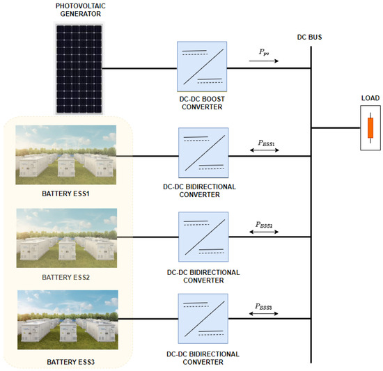
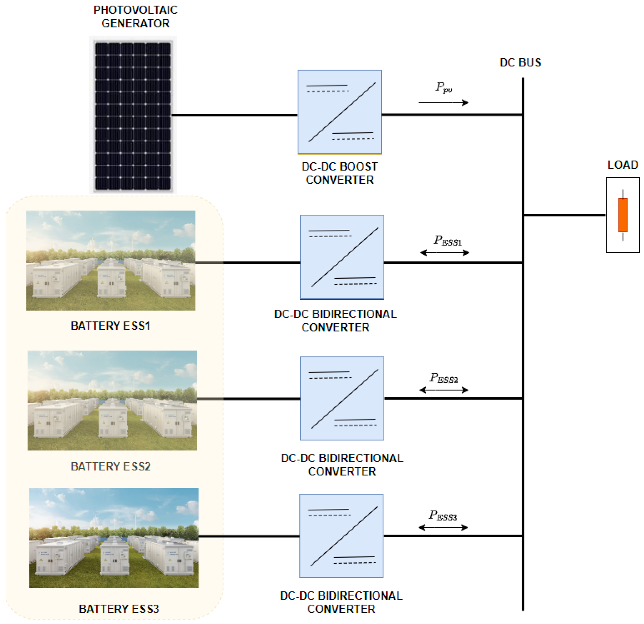
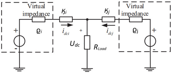
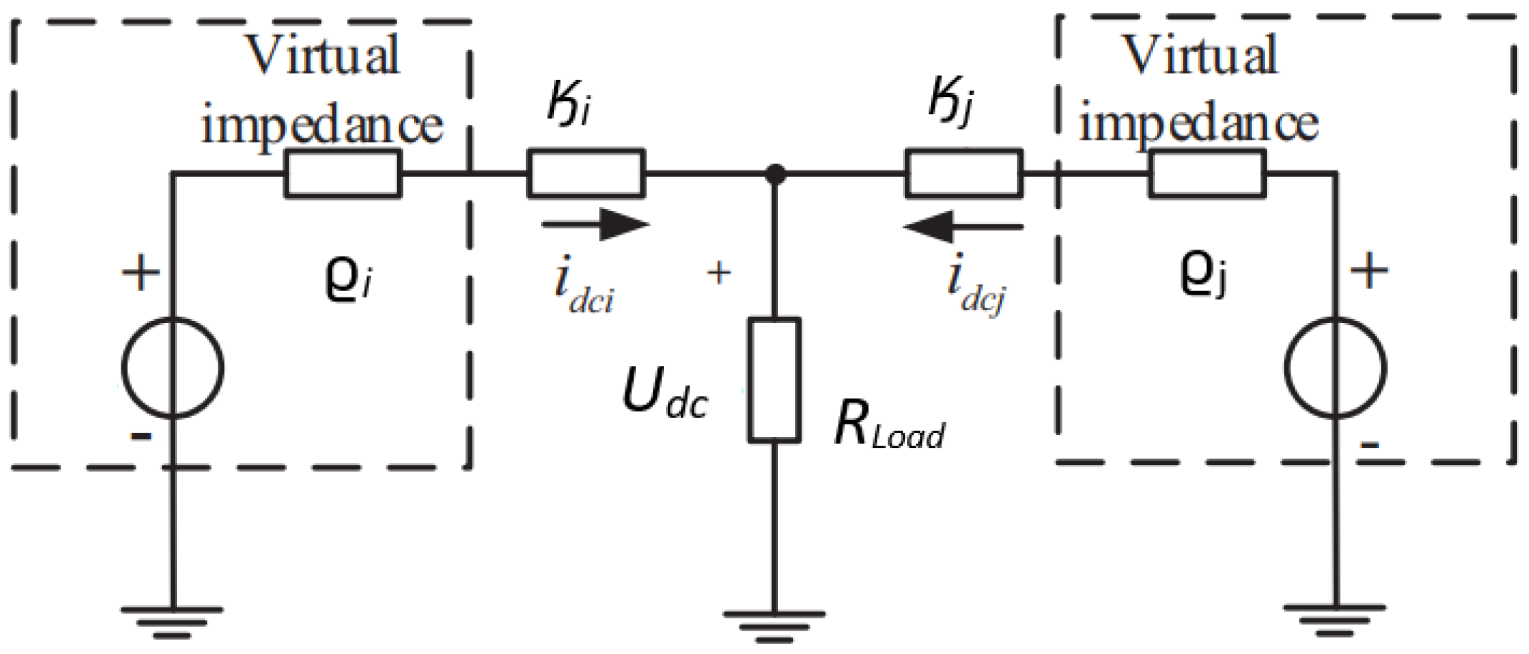
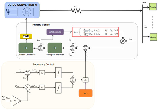
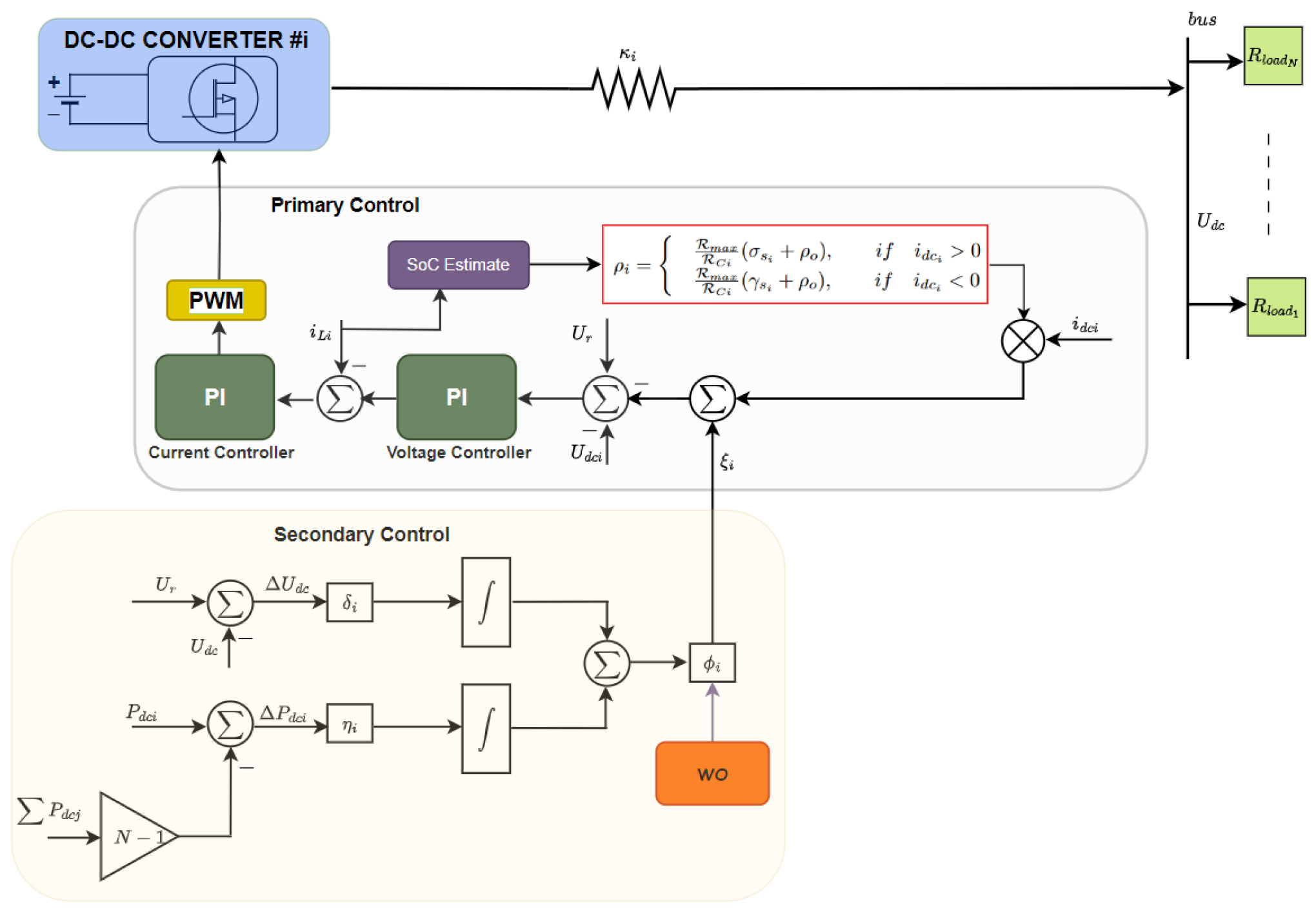
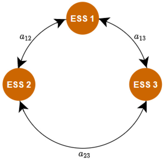
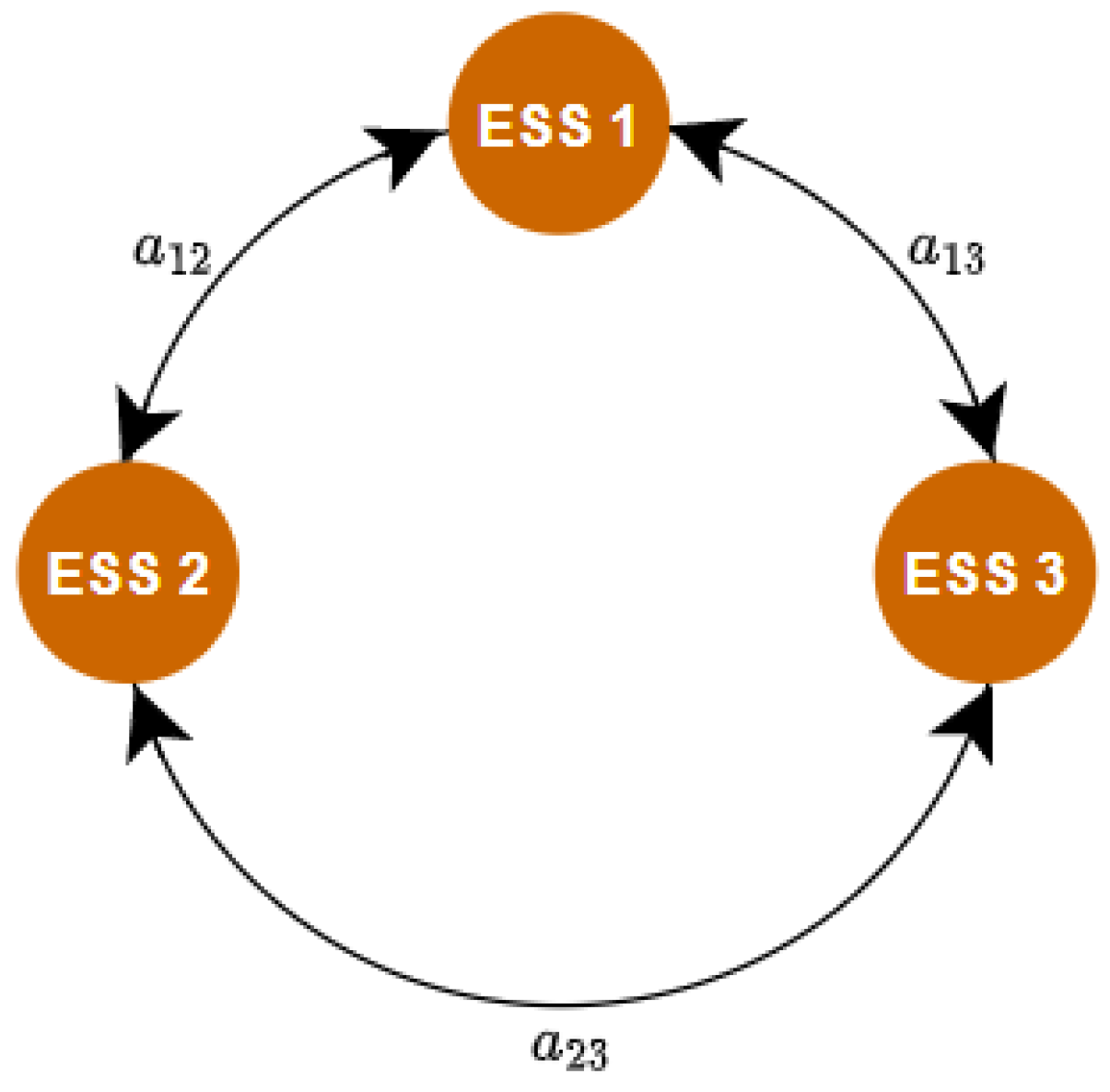
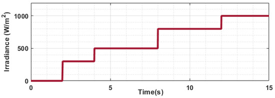
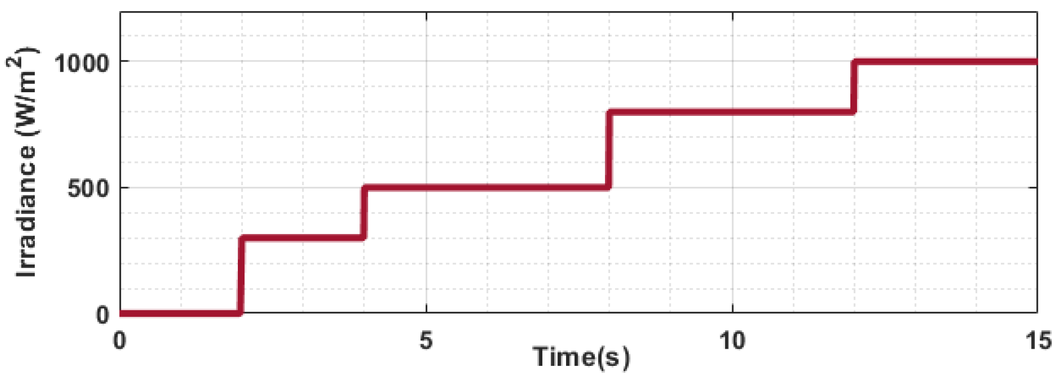
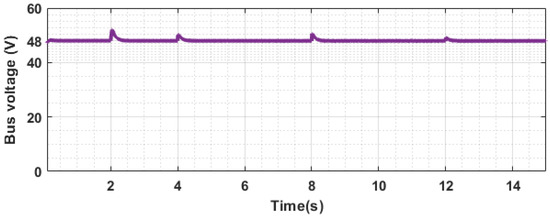
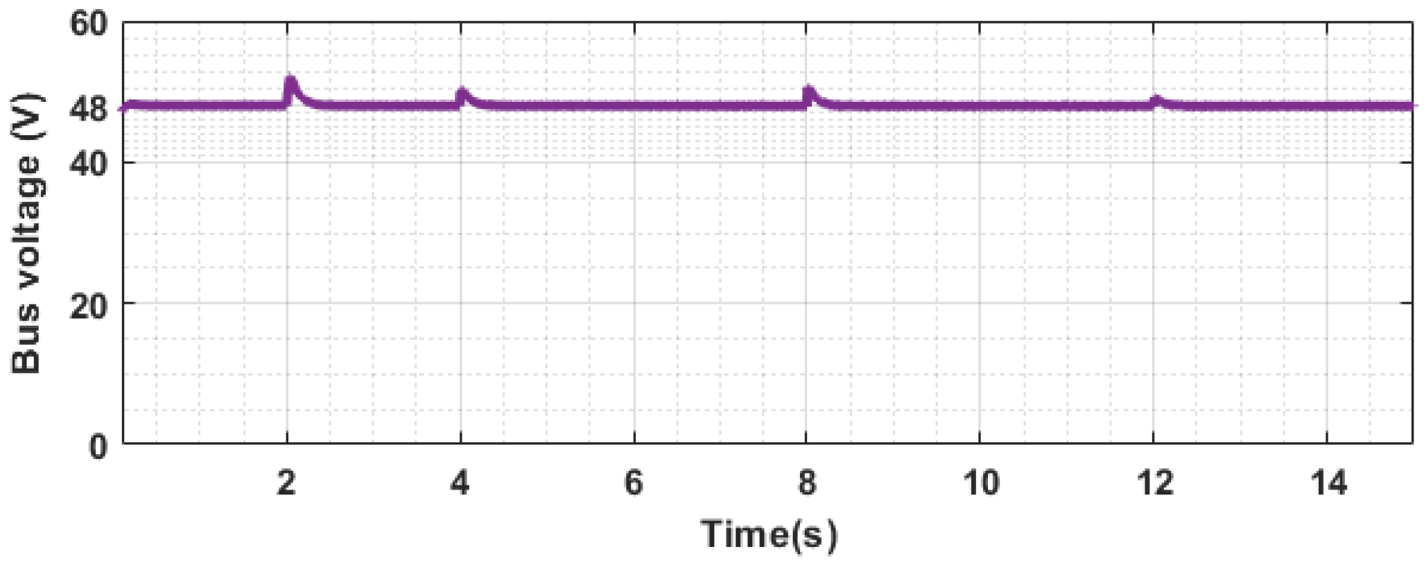
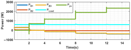
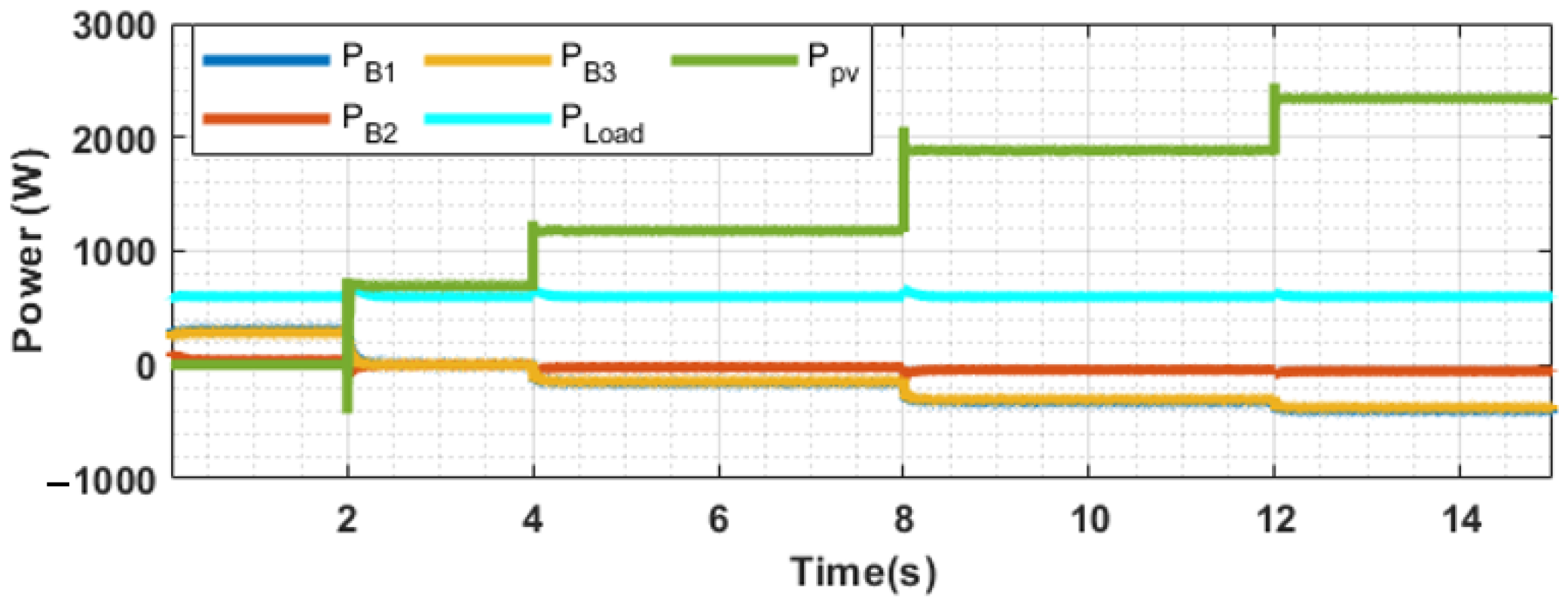
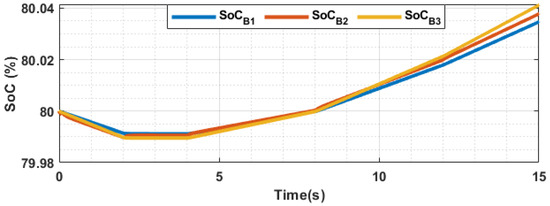
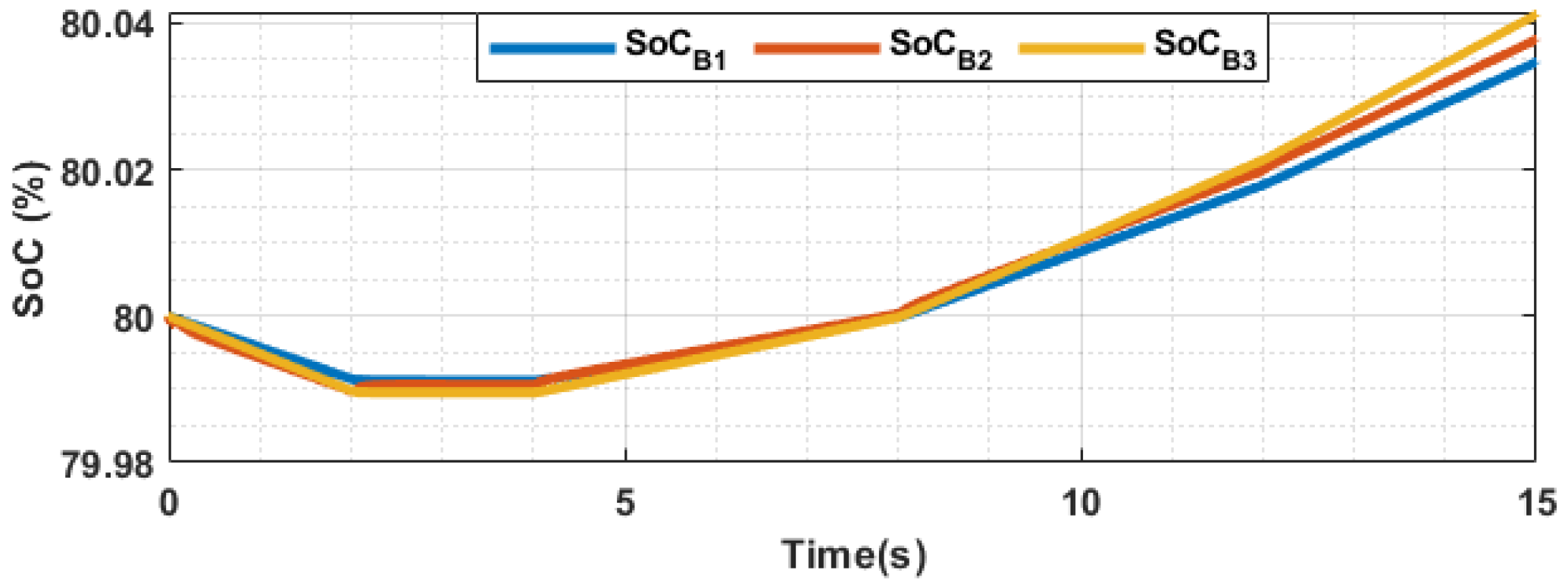
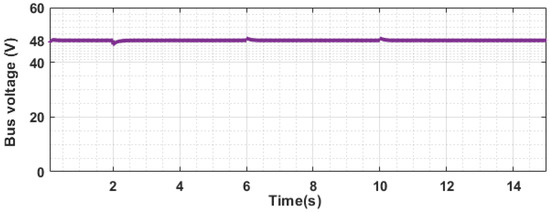
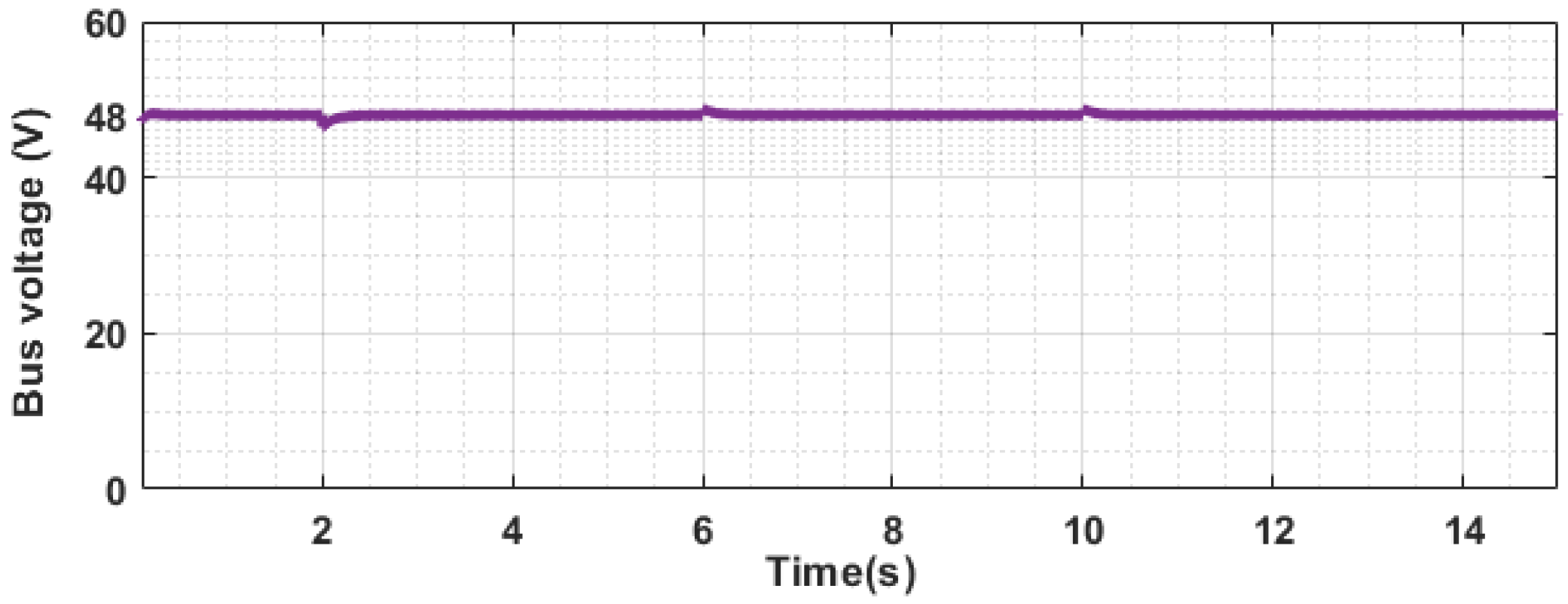
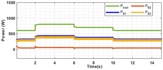
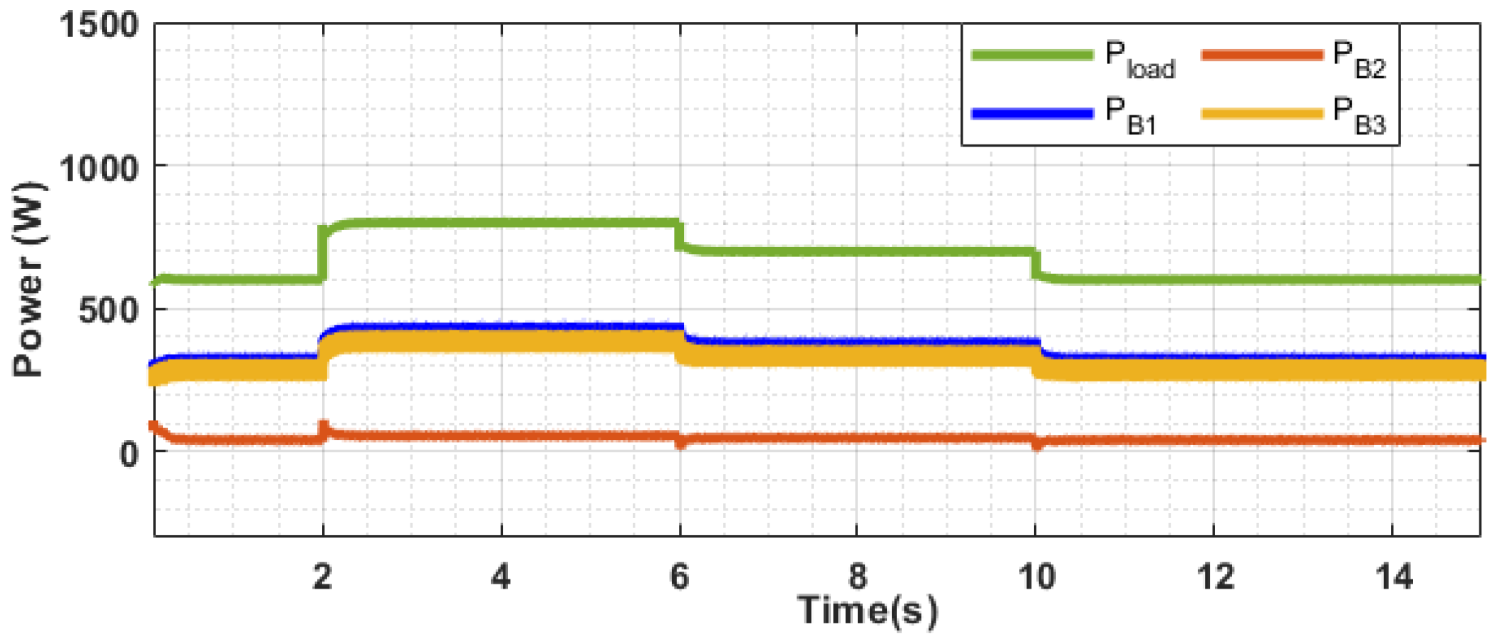
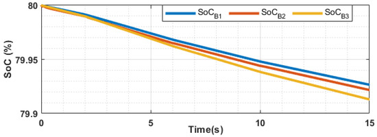
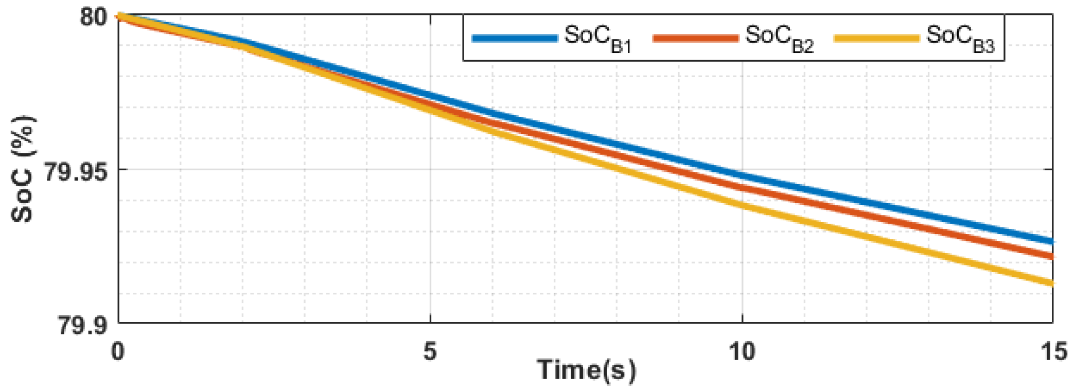
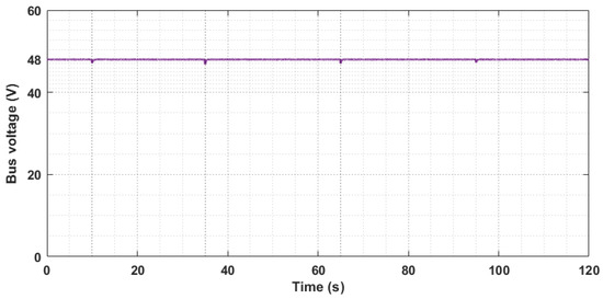
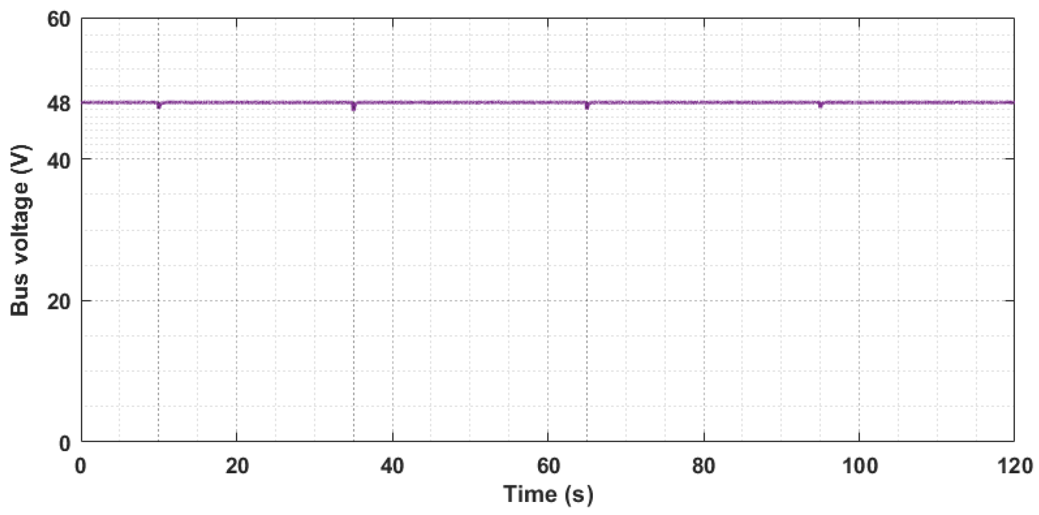
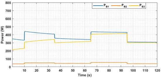
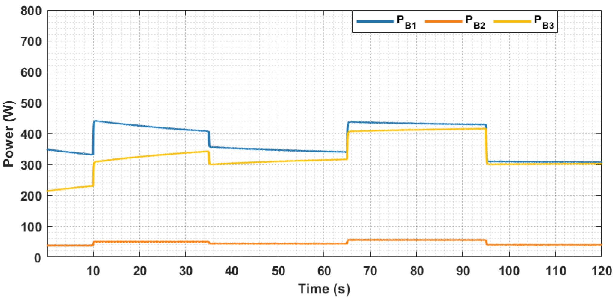
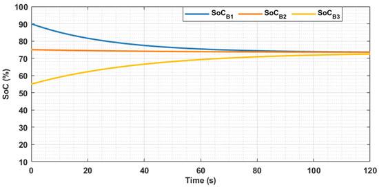
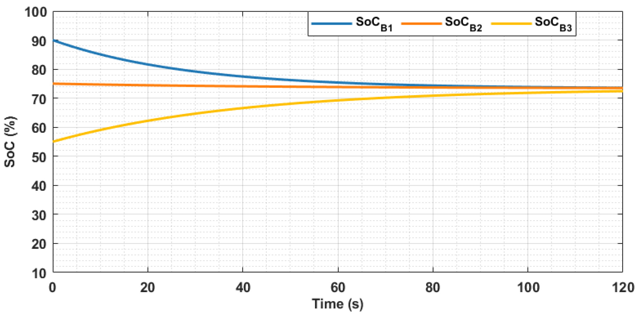
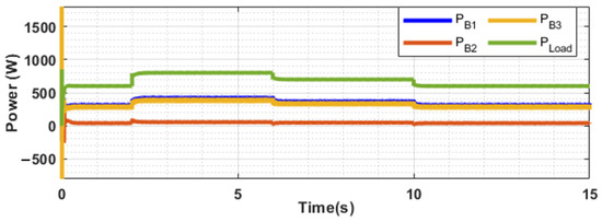
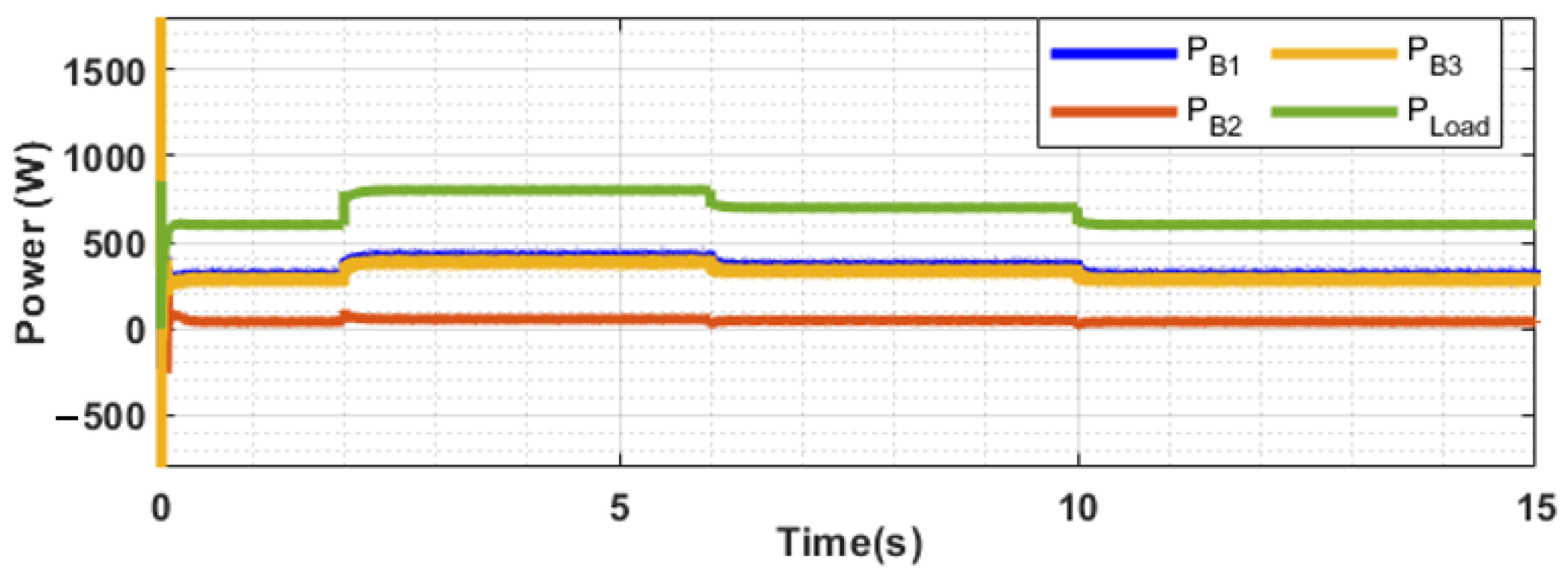
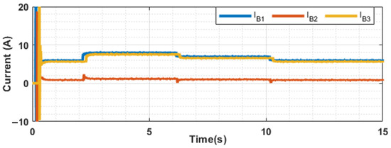
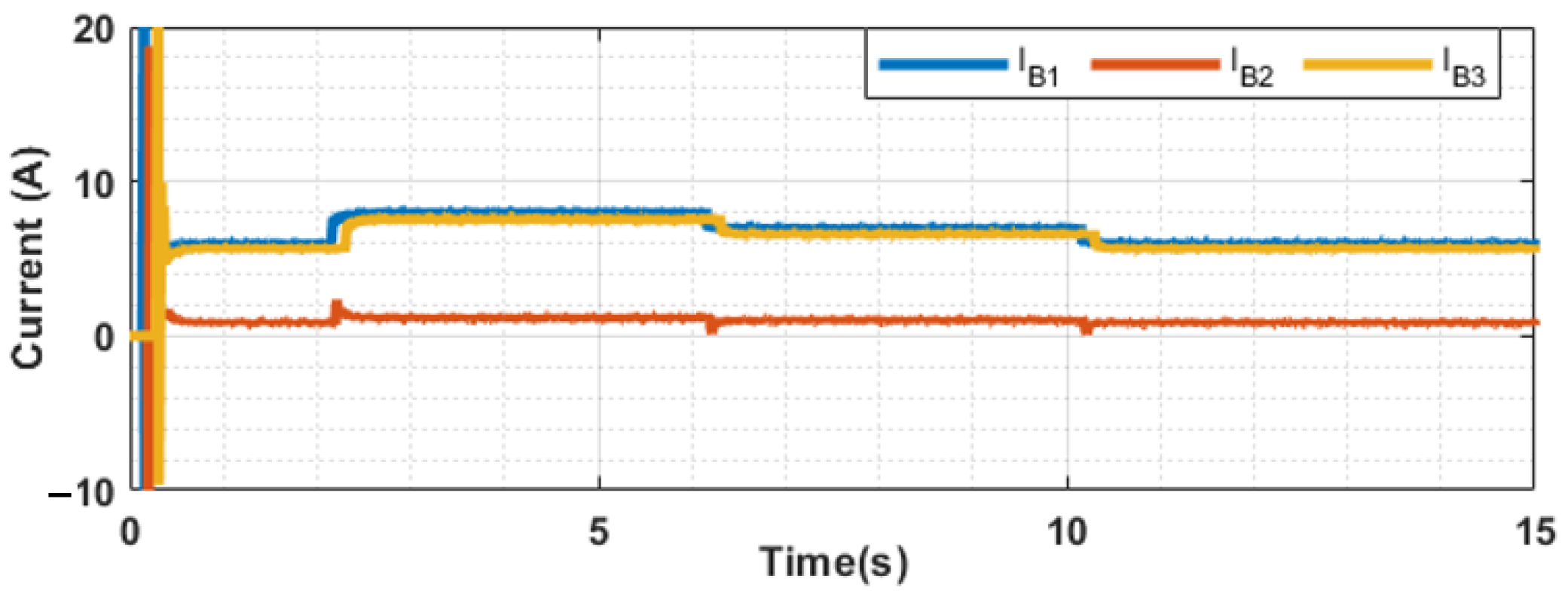
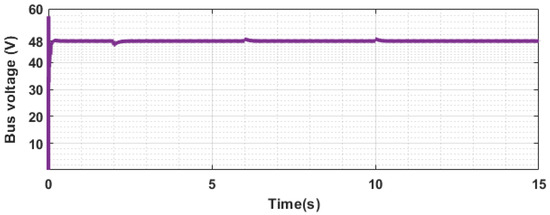
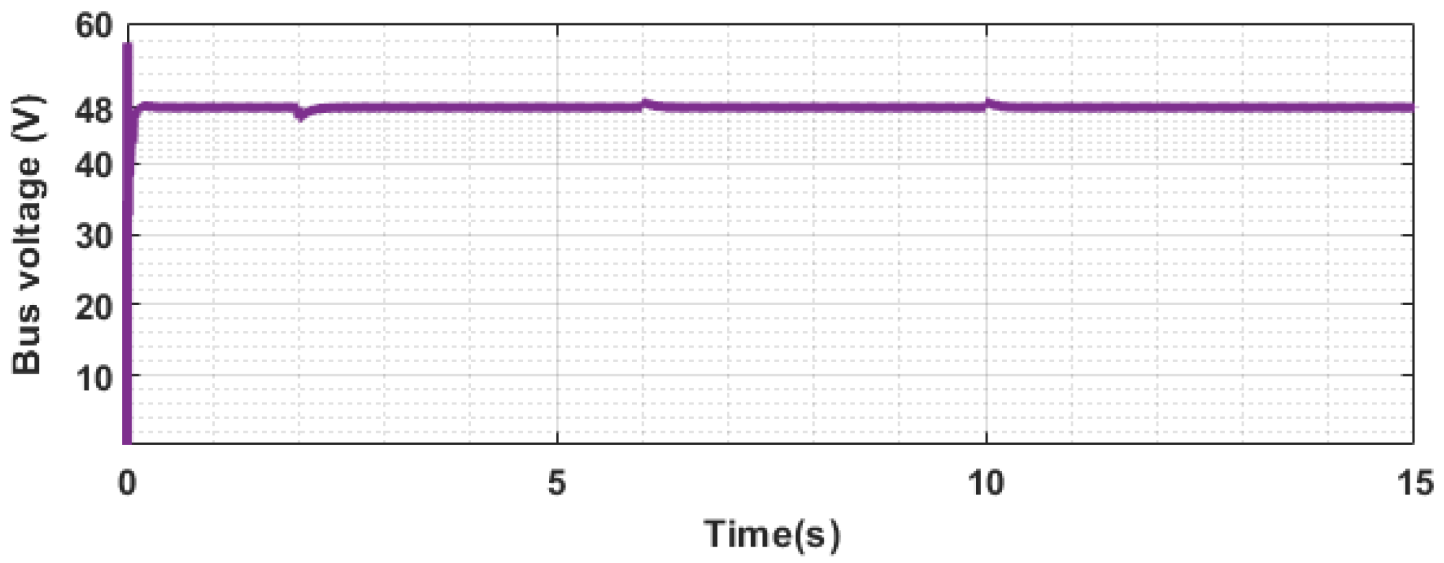
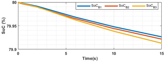
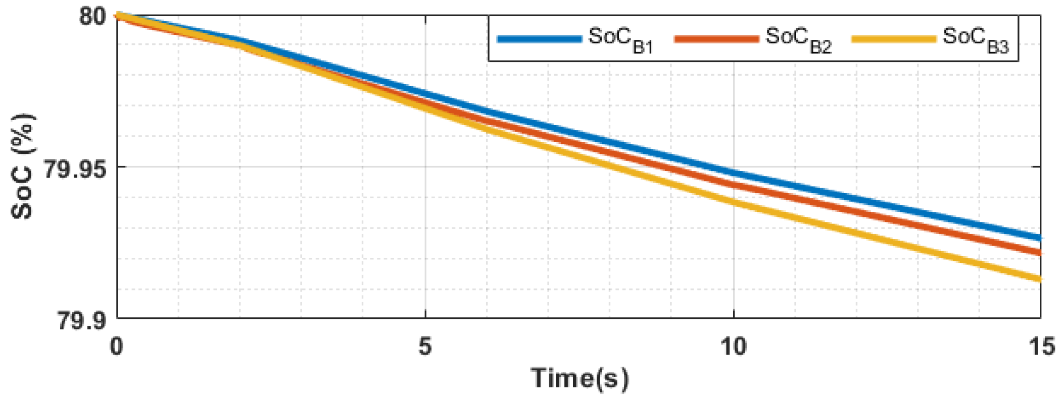
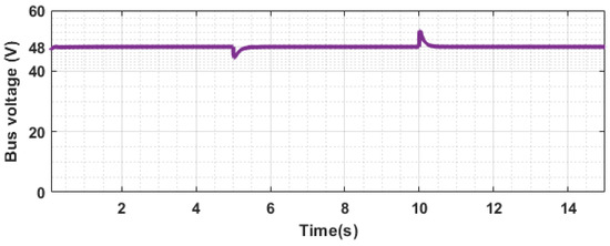
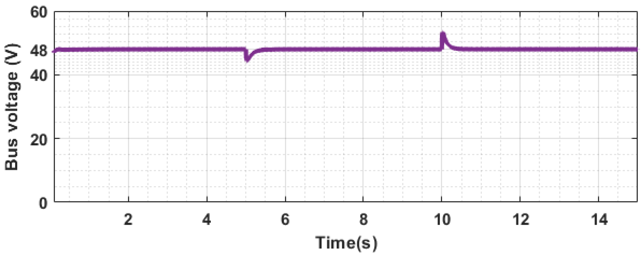
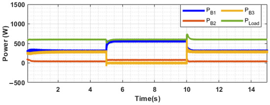
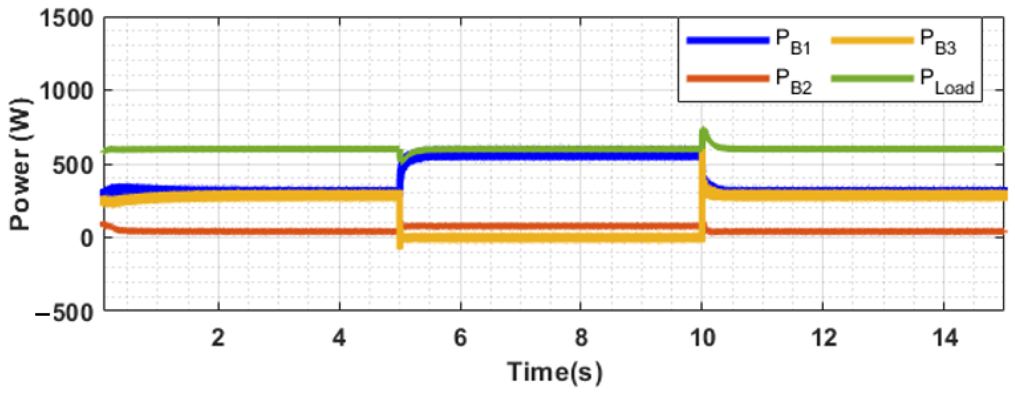
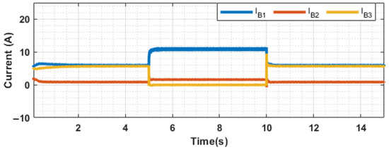
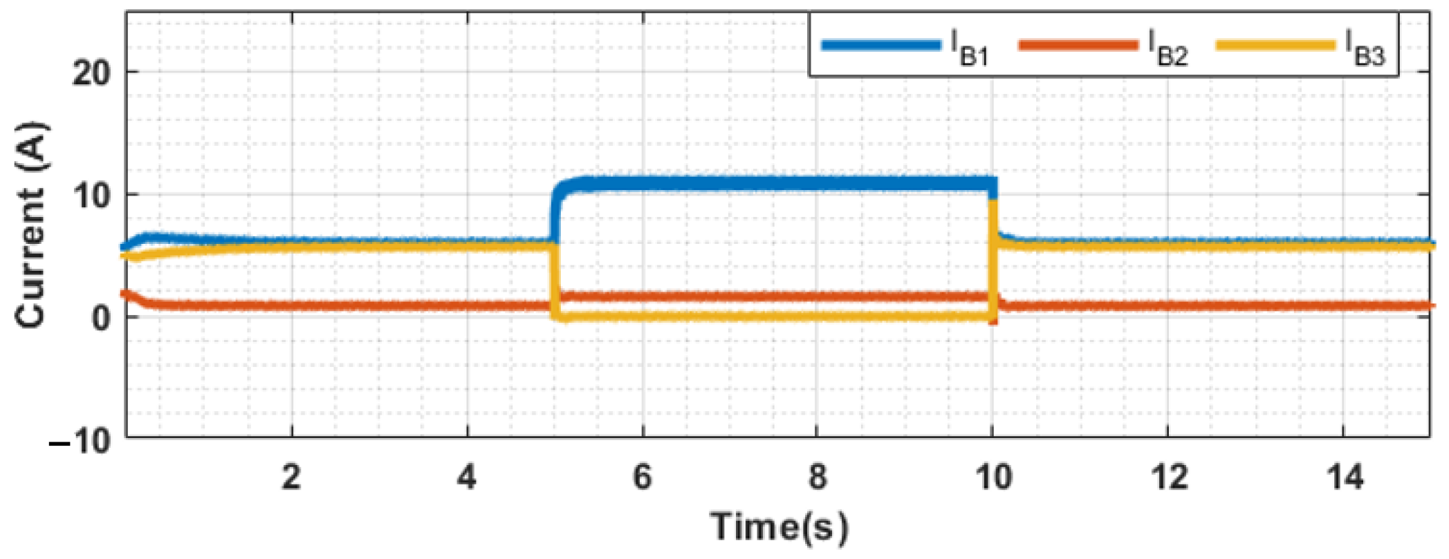
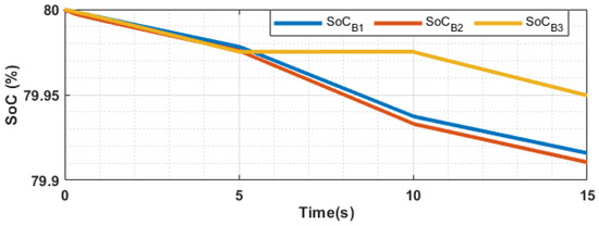
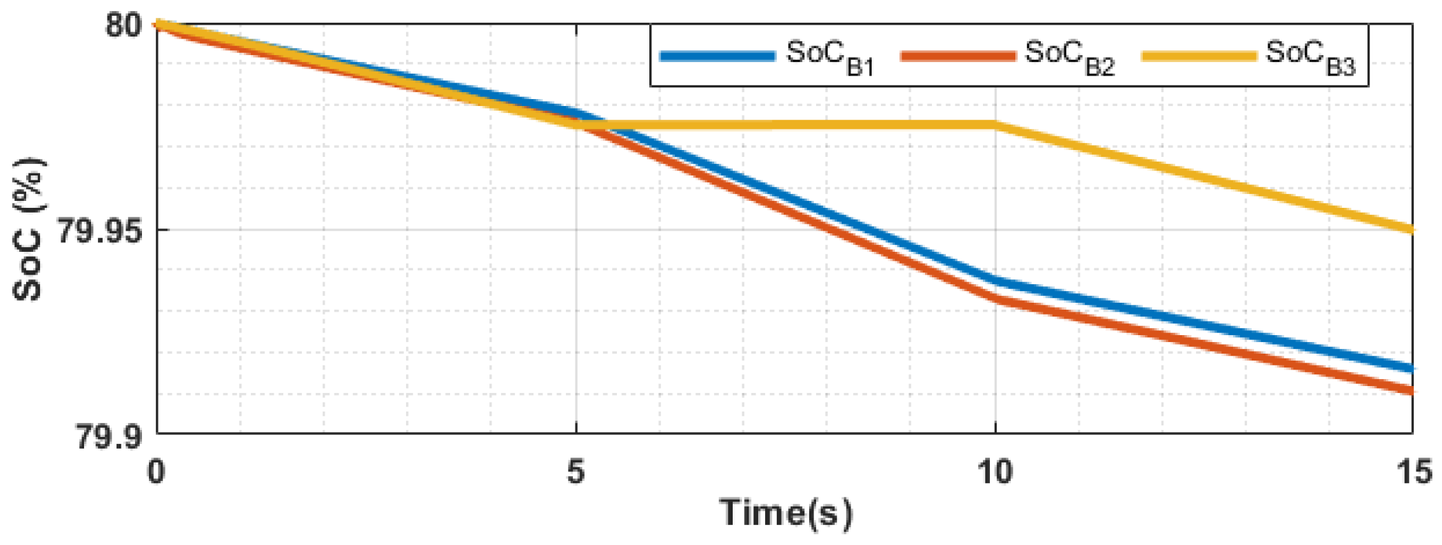

Disclaimer/Publisher’s Note: The statements, opinions and data contained in all publications are solely those of the individual author(s) and contributor(s) and not of MDPI and/or the editor(s). MDPI and/or the editor(s) disclaim responsibility for any injury to people or property resulting from any ideas, methods, instructions or products referred to in the content. |
© 2026 by the authors. Licensee MDPI, Basel, Switzerland. This article is an open access article distributed under the terms and conditions of the Creative Commons Attribution (CC BY) license.