
Article

Leakage Current Elimination for Safer Direct Torque-Controlled Induction Motor Drives with Transformerless Multilevel Photovoltaic Inverters
by
Zouhaira Ben Mahmoud
* and
Adel Khedher
LATIS—Laboratory of Advanced Technology and Intelligent Systems, Ecole Nationale d’Ingénieurs de Sousse, Université de Sousse, Sousse 4023, Tunisia
*
Author to whom correspondence should be addressed.
Electricity 2026, 7(1), 19; https://doi.org/10.3390/electricity7010019
Submission received: 11 December 2025 / Revised: 23 January 2026 / Accepted: 30 January 2026 / Published: 1 March 2026

Abstract

The use of photovoltaic (PV) water pumping technology offers a viable and sustainable alternative to conventional diesel-driven pumping systems. In PV-based pumping installations, the elimination of bulky transformers significantly reduces the overall system size and weight, which is particularly advantageous for rural and remote irrigation applications. However, removing the transformer can result in high common-mode voltage (CMV) when the induction motor is controlled using a direct torque control (DTC) scheme. This elevated CMV induces leakage currents that may damage the motor, compromise system reliability, and pose potential safety hazards. To ensure a more compact and safer PV pumping system, this paper introduces an improved DTC-based control strategy for induction motors driven by transformerless multilevel PV inverters. The proposed approach effectively suppresses leakage current by mitigating its main source, CMV, while maintaining the simple structure and dynamic performance inherent to conventional DTC. Two new look-up tables (LUTs) are developed to control the stator flux and electromagnetic torque while simultaneously eliminating leakage current. The first method, termed zero-medium vector DTC (ZMV-DTC), employs both zero and medium voltage vectors from the space vector diagram. The second, referred to as medium vector DTC (MV-DTC), utilizes only medium vectors. Numerical simulation results validate the feasibility and superior performance of the proposed algorithms in terms of leakage current suppression. Compared with a conventional DTC (C-DTC) scheme that is designed to limit the CMV, the proposed DTC algorithms achieve a much stronger reduction in the CMV, confining its amplitude to only a few volts, instead of the levels ±Vdc/6 typically produced by the C-DTC. As a result, the leakage current is effectively eliminated, ensuring safer and more reliable operation of the system.

1. Introduction

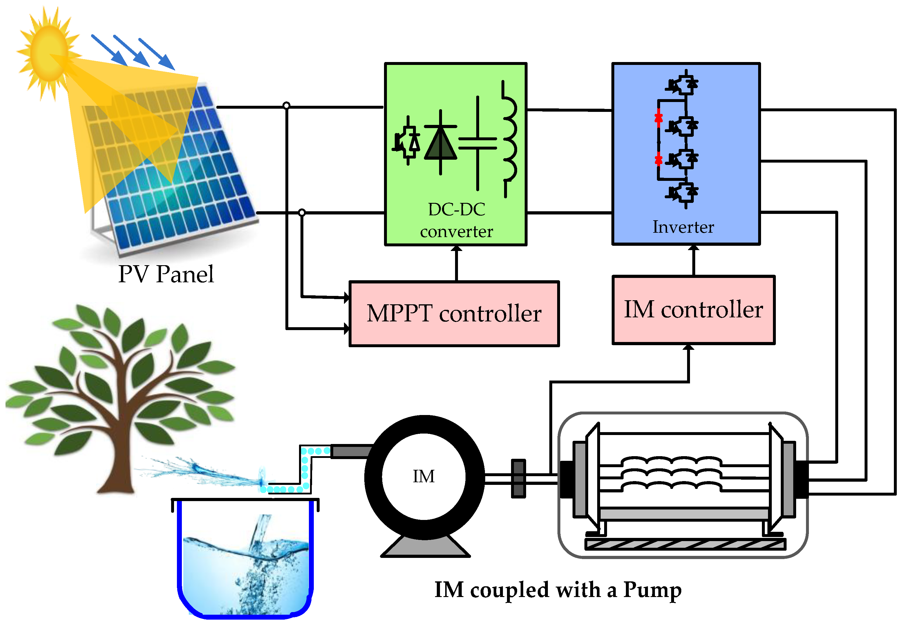
The extensive dependence on conventional electricity and diesel fuel within the agricultural sector has led to serious environmental consequences. These traditional energy sources are major contributors to greenhouse gas emissions, air and soil pollution, and the overall deterioration of natural ecosystems [1,2]. In addition, the continued use of fossil fuels such as diesel exposes farmers to fluctuations in global energy prices and rising operational expenses, a challenge that is particularly critical for isolated rural communities with limited energy access. To address these issues, renewable energy technologies have emerged as a promising alternative, providing cleaner, more sustainable, and economically resilient solutions. Their integration not only reduces the sector’s carbon footprint but also enhances energy independence and long-term productivity [3,4]. Consequently, the shift toward renewables has become essential, especially in regions that are highly vulnerable to the effects of climate change and environmental degradation. In recent years, photovoltaic (PV)-based water pumping systems have emerged as an attractive and sustainable alternative to conventional pumping solutions, especially in remote and rural areas where the electrical grid is unavailable [5,6]. Among various motor drive configurations, the induction motor (IM) combined with a direct torque control (DTC) strategy offers a simple and efficient solution for achieving high dynamic performance and robustness against parameter variations [7,8]. As illustrated in Figure 1, a PV water pumping system generally consists of several interconnected components that operate together to convert solar energy into mechanical power for irrigation. The system begins with the PV array, which captures solar radiation and converts it into direct current (DC) electricity. This DC power is then fed into a DC–DC converter, typically a boost converter equipped with a Maximum Power Point Tracking (MPPT) algorithm to ensure that the PV modules operate at their optimal power point under varying solar and temperature conditions [3,9]. The regulated DC output from the converter is subsequently supplied to a DC–AC converter, which transforms the DC voltage into AC current suitable for driving the IM. The motor, in turn, is mechanically coupled to a centrifugal pump, which delivers the required hydraulic energy for water lifting and irrigation purposes. This configuration enables efficient utilization of solar energy, offering a clean and autonomous solution for agricultural water management. The DCAC converter plays a crucial role in achieving efficient and stable energy conversion within PV systems. While conventional two-level inverters are still widely implemented, they often require either bulky filtering components or elevated switching frequencies to satisfy such performance and harmonic distortion standards [10,11]. In contrast, multilevel inverters (MLIs) have gained significant prominence in recent years, particularly within industrial and renewable energy sectors. Their key advantages include enhanced efficiency, higher power density, superior output waveform quality, and improved fault tolerance, making them an attractive alternative to traditional two-level converter standards [12,13]. The three-level Neutral Point Clamped (NPC) topology has been widely adopted in PV energy conversion systems [14] and can generally be classified into two configurations: transformer-based and transformerless designs [15,16,17]. Beyond the well-established advantages of multilevel inverter architectures, the elimination of the transformer can further enhance the PV pumping system performance. Specifically, removing the transformer significantly reduces the overall size, cost, and weight of the PV power conversion system while simultaneously increasing its energy efficiency.
However, when the PV inverter is connected to the motor through a transformerless topology, a common-mode voltage (CMV) is generated at the inverter output, which leads to leakage currents flowing through the parasitic capacitance between the motor windings and the ground. These leakage currents not only degrade the system efficiency but also increase the electromagnetic interference (EMI), accelerate motor insulation aging, reduce the lifetime of the PV cells and may even cause safety hazards or malfunction of protection devices [18,19,20]. Therefore, minimizing or eliminating the leakage current is a crucial design requirement for ensuring both safety and reliability in transformerless PV-fed induction motor drive systems. To address this issue, various solutions have been proposed in the literature, including advanced modulation techniques, CMV suppression strategies, and the use of multilevel inverter topologies.
In [21], the researchers systematically analyze how the DC-link capacitor size, filter design, and control strategies influence common-mode leakage. They demonstrate that by appropriately designing filter inductances and selecting control and topology parameters, leakage current RMS values can be reduced by up to 70%. Al-Mamoori et al. [22] propose transformerless multilevel boost inverters with a single voltage source and direct connection of PV negative to grid neutral to achieve zero leakage current while maintaining acceptable output THD and efficiency. Carvalho et al. [23] develop a topology that switches between three- and five-level modes, employing modulation strategies to keep leakage current within acceptable limits. The system is tested via the hardware-in-loop method and shows good efficiency and safety performance. Although effective, these approaches involve the use of additional components, thereby increasing both the implementation cost and the complexity of the conversion stage. In [24], a space vector modulation-based sliding mode DTC approach is introduced, offering a faster dynamic response with reduced torque and flux linkage ripples. In [25], a minimum voltage vector error-based DTC strategy is proposed for induction motor drives using a two-level inverter, which effectively minimizes torque ripple and current harmonics. In [26], a fuzzy logic-based SVM-DTC scheme is developed to regulate the speed of an induction motor fed by an indirect matrix converter. Although this method provides improved dynamic behavior, it remains relatively complex due to the use of the matrix converter and the integration of two distinct control algorithms. However, it is important to note that these studies do not address the issue of leakage current reduction, which remains a critical concern in transformerless inverter-fed motor drive systems. For leakage current reduction, several DTC-based strategies have been developed [27,28,29].
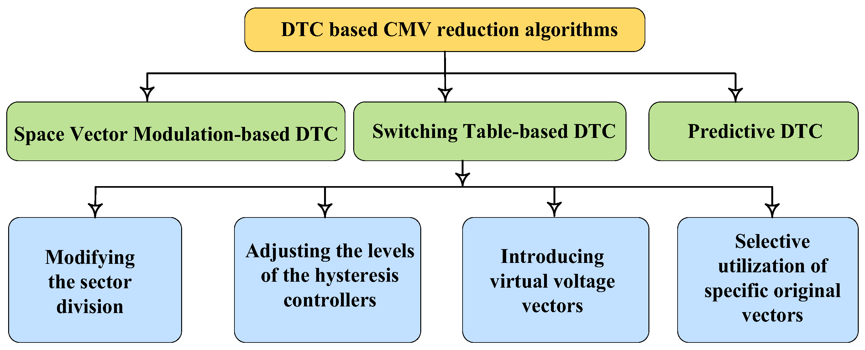
As illustrated in Figure 2, DTC schemes that aim to minimize the CMV can generally be classified into three main categories: Space Vector Modulation-based DTC (SVM-DTC) [27], Switching Table-based DTC (ST-DTC), and Predictive DTC (P-DTC) [30]. In the case of ST-DTC, various strategies have been proposed to achieve CMV reduction and performance enhancement. These include modifying the sector division of the space vector diagram, adjusting the levels of the hysteresis controllers, introducing virtual voltage vectors, or employing a selective utilization of specific original vectors. Each of these approaches aims to maintain precise torque and flux control while simultaneously minimizing leakage current associated with CMV. For example, in [29], a reduction in both torque ripple and CMV, along with neutral-point voltage balancing in a three-level inverter-fed induction motor (IM) drive, was targeted. The drive was controlled using a modified DTC technique, where voltage vectors were selected based on their capability to generate different leg or pole voltages. However, in this approach, the CMV was only partially reduced, which was insufficient to fully suppress the leakage current.
Furthermore, a twelve-sector DTC scheme for three-level inverter-fed IM drives was investigated in [31], focusing on CMV reduction through the application of specific voltage vectors. Although a 66.7% reduction in CMV was achieved, leakage current persisted, which could potentially damage the power conversion system and compromise user safety. Table 1 provides a comprehensive comparison between the proposed approach and representative methods reported in the existing literature. The comparison highlights several key performance indicators. In this paper, an enhanced DTC strategy is proposed for induction motor drives supplied by a transformerless multilevel PV inverter, with a focus on eliminating leakage current and improving overall system safety and performance. The proposed approach enables effective CMV control, which in turn reduces leakage current, while maintaining fast torque response and satisfactory overall performance. This makes the method particularly suitable for solar water pumping applications, where reliability and safety are critical. Several advantages can be highlighted when applying the proposed DTC strategy to PV water pumping systems:
  • Compact and lightweight configuration: In PV pumping systems, eliminating bulky transformer components significantly reduces the overall size and weight of the installation. This leads to more compact, portable, and cost-effective systems, particularly beneficial for rural or remote irrigation applications.
  • Enhanced system reliability: Minimizing the leakage current decreases electrical stress on the PV modules, power converters, and motor windings. As a result, the overall system durability and operational lifetime are improved, ensuring stable water supply over extended periods.
  • Improved safety and regulatory compliance: Lower CMV levels contribute to reduced leakage currents, which helps prevent insulation degradation and mitigates safety risks such as electric shocks or system faults. This ensures compliance with international safety standards for transformerless PV systems.

The remainder of this paper is organized as follows. Section 2 presents the modeling of a three-level inverter-fed induction motor. Section 3 introduces the conventional DTC strategy. Section 4 discusses leakage current issues and describes the proposed DTC approach. Section 5 provides simulation results and discussions, and Section 6 concludes the paper.
Table 1. Performance comparison between the proposed DTC method and conventional strategies.
Ref.Method/StrategyInverter/Motor TypeCMV ReductionAdditional FeaturesLimitations
[27], 2022DTC–SVM with virtual vectorsTwo-level/five-phase induction motorPartial reduction-Constant switching frequency-Increased computational complexity
[29], 2022ST-DTC using specific voltage vectorsThree-level NPC/three-phase induction motorPartial reduction-Balancing of the dc-link neutral point-Restricted DC-bus utilization ratio
[30], 2024DTC–SVM applied to modified inverter topologyThree-phase two level h-9/three-phase induction motorPartial reduction-Improved current quality-The use of three additional switches
-Increased computational complexity
[32], 2025ST-DTC using twelve sectorsThree-level NPC/three-phase induction motorPartial reduction-Balancing of the dc-link neutral point-A more complex algorithm
Proposed workST-DTC using specific voltage vectorsThree-level NPC/three-phase induction motorCMV and leakage current elimination-Fast dynamic response
-Simple algorithm structure
-No consideration given to the DC-link neutral point balance

2. Modeling of Three-Level Three-Phase Inverter

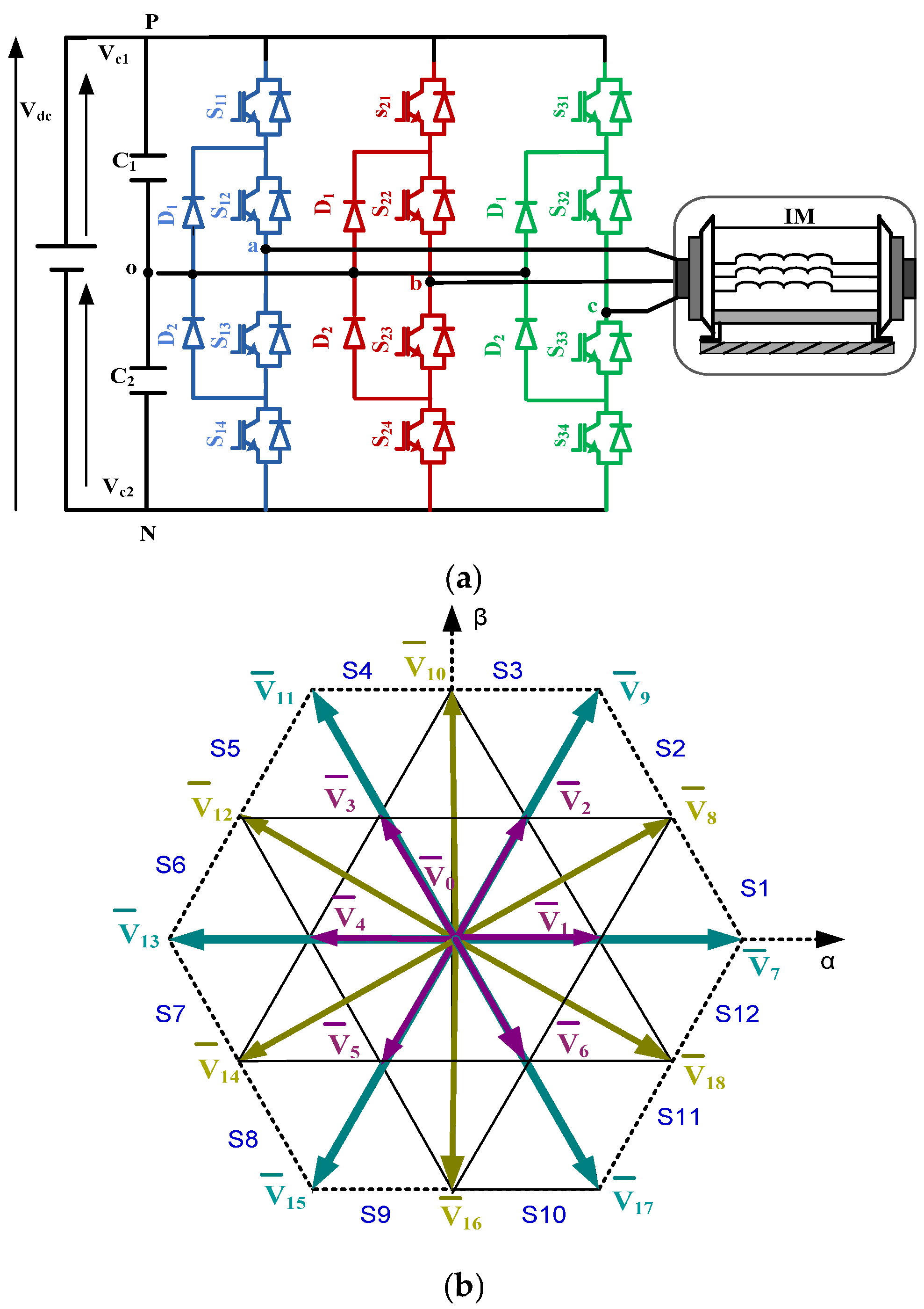
Figure 3a depicts a three-phase Neutral Point Clamped (NPC) inverter composed of three legs. In this configuration, S11 and S13 operate as complementary switches, with S12 and S14 similarly paired to ensure proper operation of the inverter. The possible switching states for a given phase are 1, 0, and −1. Table 2 presents the corresponding device switching states for phase a, along with the associated inverter pole voltage. In a three-phase, three-level NPC inverter, there are a total of 33 = 27 possible switching states, which are illustrated in the space vector diagram shown in Figure 3b. Of these, three correspond to zero vectors V ¯ 0 , which produce no phase voltage difference and do not contribute to torque production, while the remaining vectors are active vectors, responsible for generating the desired voltage space vectors and controlling the motor’s torque and flux. These active vectors are categorized into three types:
  • Large: The six largest vectors, labeled V ¯ 7 (PNN), V ¯ 9 (PPN), V ¯ 11 (NPN), V ¯ 13 (NPP), V ¯ 15 (NNP), and V ¯ 17 (PNP).
  • Small: Two sets of vectors that are half the magnitude of the full vectors: V ¯ 1 (POO/ONN) , V ¯ 2 (PPO/OON), V ¯ 3 (OPO/NON), V ¯ 4 (OPP/NOO), V ¯ 5 (OOP/NNO), and V ¯ 6 (POP/ONO).
  • Medium: The six vectors in the middle range: V ¯ 8 (PON), V ¯ 10 (OPN), V ¯ 12 (NPO), V ¯ 14 (NOP), V ¯ 16 (ONP), and V ¯ 18 (PNO).
Figure 3. Three-level NPC inverter coupled with IM (a) inverter topology, (b) space vector diagram and sector division.
Electricity 07 00019 g003
Table 2. Switching state for three-level NPC inverter.
S11S12S13S14Switching StateOutput Voltage
11001 + V dc / 2
011000
0011−1 V dc / 2
The mathematical model of the three-level voltage inverter can be expressed as follows:
V a n = V d c 6 2 S a S b S c V b n = V d c 6 S a + 2 S b S c V c n = V d c 6 S a S b + 2 S c
where Sa, Sb, and Sc are the command signals of phases a, b and c, respectively, and they are defined as follows:
S a = j = 1 2 S 1 j S b = j = 1 2 S 2 j S c = j = 1 2 S 3 j

3. Direct Torque Control Modeling

To design the control strategy for the IM, the system model is derived using the Concordia transformation. This transformation enables a reduced-order and simplified representation of the motor, facilitating control analysis and allowing the system dynamics to be expressed by the following set of equations [32]:
  • Electrical equations:
V s α = R s i s α + d φ s α d t V s β = R s i s β + d φ s β d t V r α = R r i r α + d φ r α d t + ω m φ r β V r β = R r i r β + d φ r β d t ω m φ r α
  • Magnetic equations:
φ s α = L s i s α + L m i r α φ s β = L s i s β + L m i r β φ r α = L r i r α + L m i r α φ r β = L r i r β + L m i r α
  • Mechanical equation:
T e m T r = J d d t Ω + f Ω
The operating principle of the DTC is to regulate the flux and torque of the induction motor without direct measurement of these quantities. This is accomplished by estimating the flux and torque and comparing the estimates to their respective reference values. The stator flux vector is derived from the measured stator voltages and currents of the motor. The corresponding expressions for the stator flux components are given in [33]:
φ s α = V s α R s i s α d t φ s β = V s β R s i s β d t
Based on the estimated stator flux vector, its magnitude and the corresponding angle relative to the stator reference frame can be calculated as follows:
φ s = φ s α 2 + φ s β 2 θ s = tan - 1 φ s β φ s α
One of the available inverter voltage vectors is carefully selected to regulate both the magnitude and position of the stator flux, and consequently the rotor flux, based on the observed variations in the stator flux. This selection ensures fast torque response and precise flux control without the need for a feedback current controller.
The estimated torque is expressed as follows:
T e m = 3 2 p Im φ ¯ s . I ¯ s *
Resolving Equation (8), the estimated torque is then derived as follows:
T e m = 3 2 p ( φ s α . i s β φ s β . i s α )
Using the forward Euler approximation, the following relationship is deduced from (6):
φ ¯ s k + 1 = φ ¯ s k + V ¯ s k . T s R s I ¯ s k . T s
where Ts is the sampling period.
The variation in stator flux can be then derived as
Δ φ ¯ s k + 1 = V ¯ s k . T s R s I ¯ s k . T s V ¯ s k . T s
Also, the variation in the electromagnetic torque is obtained from (8):
Δ T e m k + 1 = 3 2 p Im Δ φ ¯ s k + 1 . I ¯ s * + φ ¯ s . Δ I ¯ s * k + 1
Since in DTC, the current is not directly controlled but depends on the applied voltage, the variation in torque can be approximated such that
Δ T e m k + 1 = 3 2 p Im Δ φ ¯ s k + 1 . I ¯ s *
Equation (11) shows that the flux variation depends directly on the voltage applied by the inverter. To increase the flux, a voltage vector should be applied in the direction of the existing stator flux. To decrease the flux, a vector that partially opposes the current flux should be applied. To maintain the flux constant, the zero vector can be applied. According to Equation (13), the torque, in turn, depends on the flux variation projected onto the stator current. To increase the torque, a voltage vector should be chosen that increases in a direction maximizing the angle between flux and current so that the imaginary part is positive. Conversely, to decrease the torque, a vector that reduces this projection should be applied, or the zero vector can be used if torque reduction is prioritized.

4. Leakage Current Issues and Proposed Safer DTC Approach

4.1. Leakage Current Issues in Three-Level NPC PV Inverter

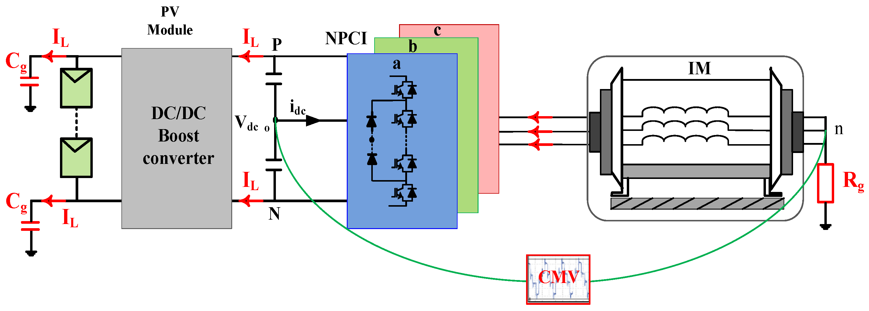
When the induction motor is supplied by an inverter, rapid switching actions generate high dv/dt voltage transitions, which in turn produce a common-mode voltage (CMV) at the inverter output [20]. These voltage transitions drive circulating currents through the path created by the parasitic circuit, the NPC inverter, and the different components of the IM drive as shown in Figure 4. Prolonged exposure to these leakage currents can lead to bearing deterioration, shorten the lifetime of the PV cells, decrease the overall system reliability, and may trigger malfunctions in protective devices, such as relays, thus compromising operational safety [34].
To effectively suppress the leakage current, it is essential to control the CMV, which represents its primary cause. The CMV can be expressed in terms of the inverter pole voltages using the following relation [35,36]:
V c m = ( V a o + V b o + V c o ) / 3
This voltage can also be expressed in terms of the switching states of the VSI such as
V c m = V d c 6 S a + S b + S c
The leakage current value depends on the amplitude and frequency of the CMV fluctuations, in addition to the value of the parasitic capacitance Cg [37]. In turn, the leakage capacitance value depends on many factors, such as PV panel and frame structure, dust or salt covering the PV panel, and weather conditions. The leakage current is expressed as follows:
i L = i a + i b + i c = C g d V c m d t
The magnitude of this current is primarily determined by the amplitude of the CMV and its rate of variation. When both the CMV amplitude and its periodic variations are small, the resulting leakage current remains low. In a three-level inverter, the 27 space vectors generate different CMV levels. The zero vector corresponding to the switching state (111) produces pole voltages of Vao = +Vdc/2, Vbo = +Vdc/2, and Vco = +Vdc/2. Hence, according to (14), the resulting CMV is +Vdc/2. Similarly, the zero vector with state (−1−1−1) yields a CMV level of −Vdc/2, while state (000) results in a zero CMV level. Therefore, the zero vectors can produce three distinct CMV levels, where states (111) and (−1−1−1) lead to higher CMV magnitudes, which in turn cause higher leakage currents. Moreover, the six large voltage vectors generate CMV levels of ±Vdc/6. In contrast, the six small vectors can produce four different CMV levels, since each one has two switching states that yield either ±Vdc/6 or ±Vdc/3. Additionally, the six medium vectors result in a zero CMV level. In the conventional DTC scheme, all types of voltage vectors are utilized to regulate both torque and flux. Consequently, the CMV amplitude fluctuates among several levels, reaching a maximum value of Vdc/2 when zero vectors are applied. This rapid variation results in a high rate of change in CMV, which in turn generates significant leakage current.

4.2. Proposed Safer DTC Approach

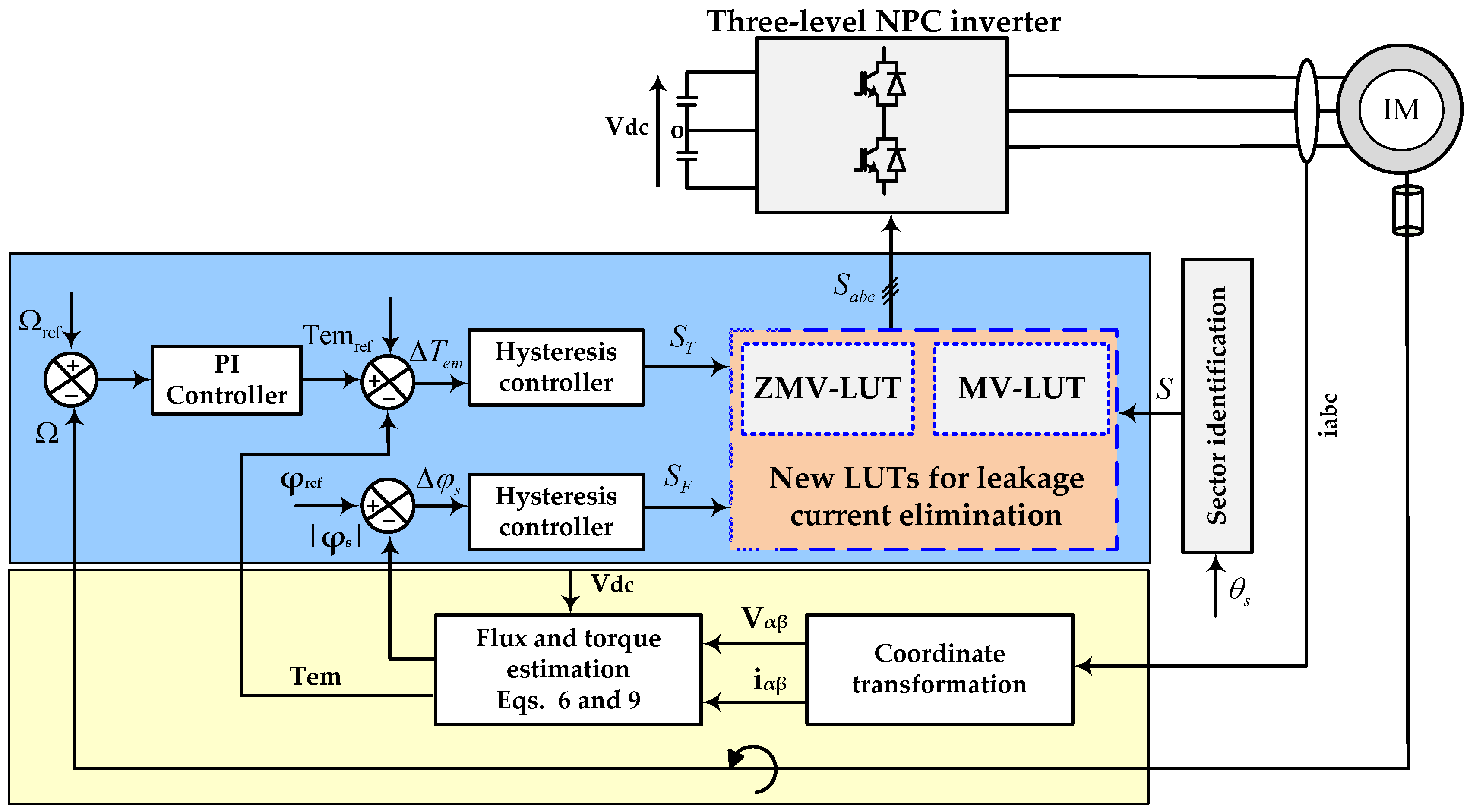
To resolve the serious problems of the leakage current, a software solution using improved look-up tables based on DTC algorithms is proposed. The operation of the proposed DTC algorithm is depicted in Figure 5. The difference between the reference and actual motor speed is first computed and supplied to a proportional–integral (PI) controller. The PI controller then generates the reference electromagnetic torque, which is compared with its estimated value. The resulting torque error is applied to the torque comparator, while the stator flux error is fed to the flux comparator. The outputs of these two comparators (ST and SF) with the selected sector are subsequently used to access the look-up table (LUT), which determines the appropriate voltage vector to maintain the torque and stator flux in the hysteresis band.
The two digital control laws, ST and SF, provided by the hysteresis controllers are determined according to the following algorithm:
S T = 1 i f Δ T H T 0 i f Δ T H T S F = 1 i f Δ F H F 0 i f Δ F H F
where HT and HF are the hysteresis bands of the electromagnetic torque and stator flux, respectively.
In order to effectively suppress the leakage current, the space vectors used in the look-up table must be carefully chosen. To achieve this objective, two new look-up tables are developed based on a space vector diagram divided into twelve sectors (S1–S12), each spanning 30°, as illustrated in Figure 3b. These sectors serve to identify the instantaneous position of the stator flux as it rotates within the space vector diagram of the three-level NPC inverter. The design principle of each table is based on selecting suitable space vectors capable of increasing or decreasing the torque and flux according to the output states of the hysteresis controllers, while keeping the CMV as close to zero as possible, since it represents the primary source of leakage current.

4.2.1. Look-Up Table Based on Zero and Medium Vectors (ZMV-LUT)

The proposed ZMV-LUT-based DTC employs only voltage vectors that maintain a zero CMV level. Specifically, it uses the six medium vectors together with the zero vector (000), ensuring that the CMV remains clamped to zero during each switching period and that its variation rate is minimized. Regardless of the flux demand, the zero vector is applied when a torque reduction is required. Torque is prioritized over flux in DTC to achieve fast dynamic response and maintain precise mechanical output, while temporary flux deviations have minimal impact on overall motor performance. Medium vectors are employed for all other combinations of torque and flux states (ST and SF).
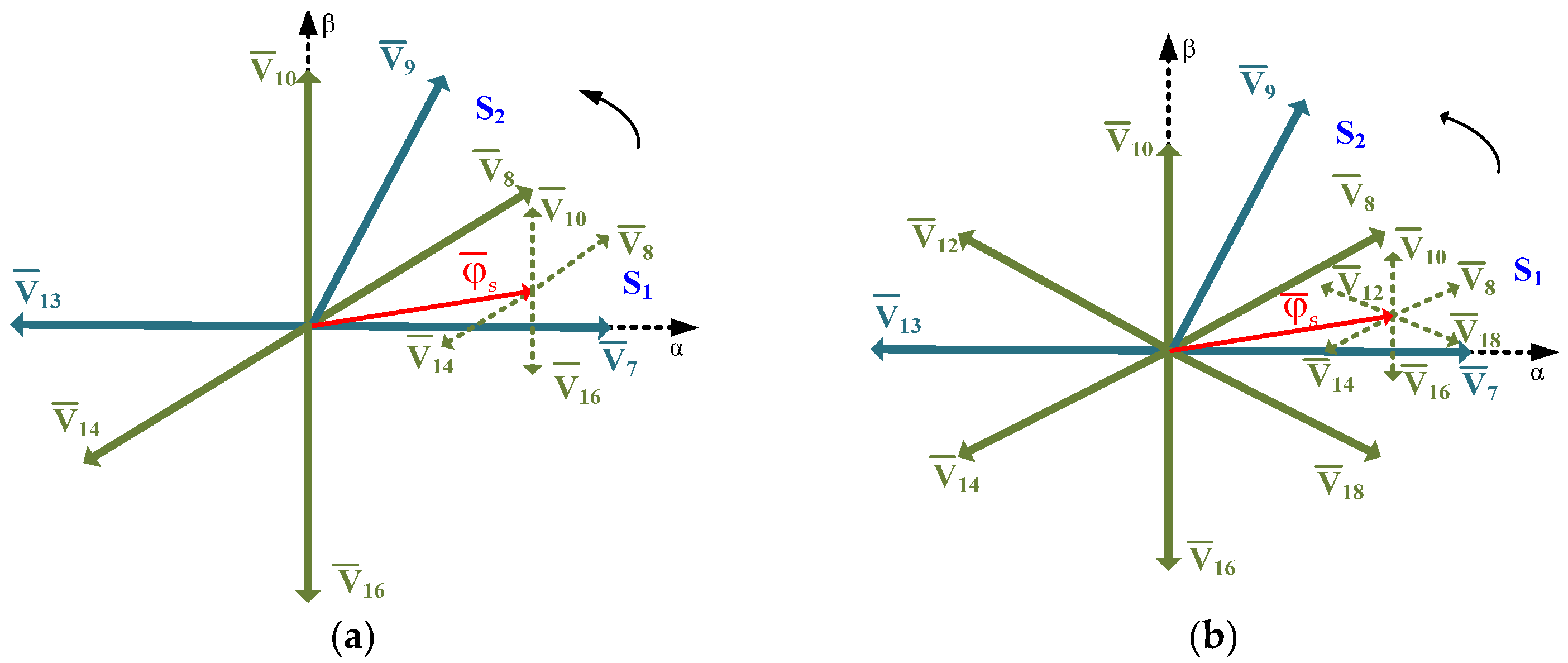
For a clearer understanding, let us consider the case where the reference stator flux lies in the first sector of the space vector diagram, as illustrated in Figure 6a. In this sector, vectors V ¯ 8 and V ¯ 10 are the closest medium vectors aligned with the reference flux vector. According to the relationship expressed in Equations (11) and (13), applying the medium vector V ¯ 8 increases both the stator flux and electromagnetic torque magnitudes due to its positive direct and quadrature components. In contrast, the application of vector V ¯ 10 increases the torque magnitude through its positive quadrature component while maintaining the flux amplitude constant, since its direct component is zero. Consequently, the medium vector V ¯ 8 is suitable for the condition (ST = 1, SF = 1), where both torque and flux must be increased, whereas vector V ¯ 10 is selected for the case (ST = 1, SF = 0), when only the torque needs to be increased while the flux remains unchanged. Extending this approach to the twelve operating sectors leads to the derivation of the appropriate switching table, as presented in Table 3.

4.2.2. Look-Up Table Based on Medium Vectors (MV-LUT)

The core concept of this approach lies in employing a single type of space vector capable of simultaneously controlling the electromagnetic torque and stator flux while maintaining a constant CMV. This goal can be achieved by using only medium vectors, ensuring that the CMV remains continuously clamped to zero. Compared with the ZMV-LUT method, the main difference is that the zero space vector used for the hysteresis controller output states (ST = 0, SF = 0) and (ST = 0, SF = 1) is replaced by a medium space vector. As an illustrative example, consider the case where the reference stator flux is located in sector 1, as depicted in Figure 6b. The four medium vectors located near the reference flux vector are V ¯ 8 , V ¯ 10 , V ¯ 12 , and V ¯ 18 . Among them, the closest vectors, V ¯ 8 and V ¯ 18 , provide similar positive direct components that tend to increase the stator flux amplitude, but they exhibit opposite quadrature components. Therefore, the medium vector V ¯ 8 is selected for the state (ST = 1, SF = 1), while V ¯ 18 is chosen for (ST = 0, SF = 1). Furthermore, vector V ¯ 10 is aligned with the quadrature axis and has a null direct component, making it suitable for the condition (ST = 1, SF = 0). On the other hand, vector V ¯ 12 partially opposes the reference flux vector, providing negative direct and quadrature components, which satisfies the requirement for (ST = 0, SF = 0). Following the same reasoning for the remaining sectors, the corresponding medium-vector-based look-up table is derived and presented in Table 4.

5. Simulation Results and Discussions

In this section, numerical simulations are conducted to validate the proper functioning of the proposed DTC algorithms. A comparative analysis is also performed between the two suggested strategies for leakage current mitigation and a DTC method presented in [38], referred to in this work as conventional DTC (C-DTC), based on various performance indicators such as their ability to follow the torque and flux references and, more specifically, their effectiveness in minimizing the CMV and consequently reducing the leakage current amplitude. The conversion system and IM parameters are listed in Table 5.
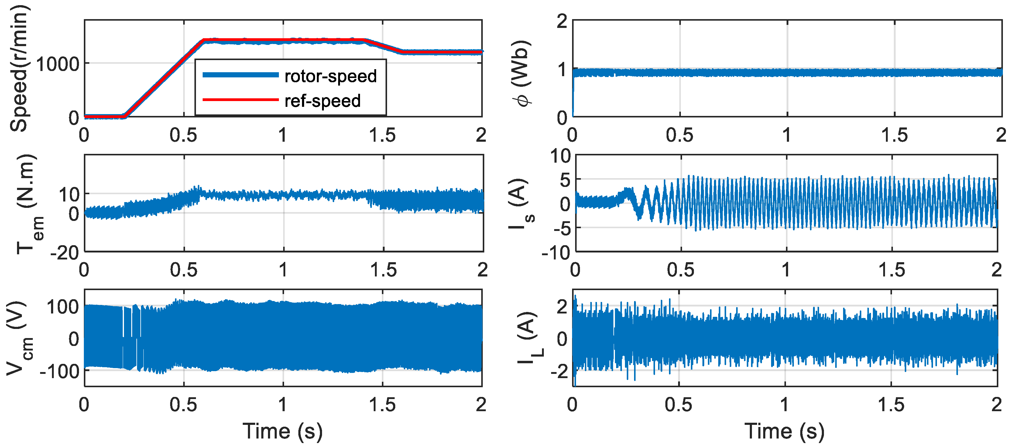
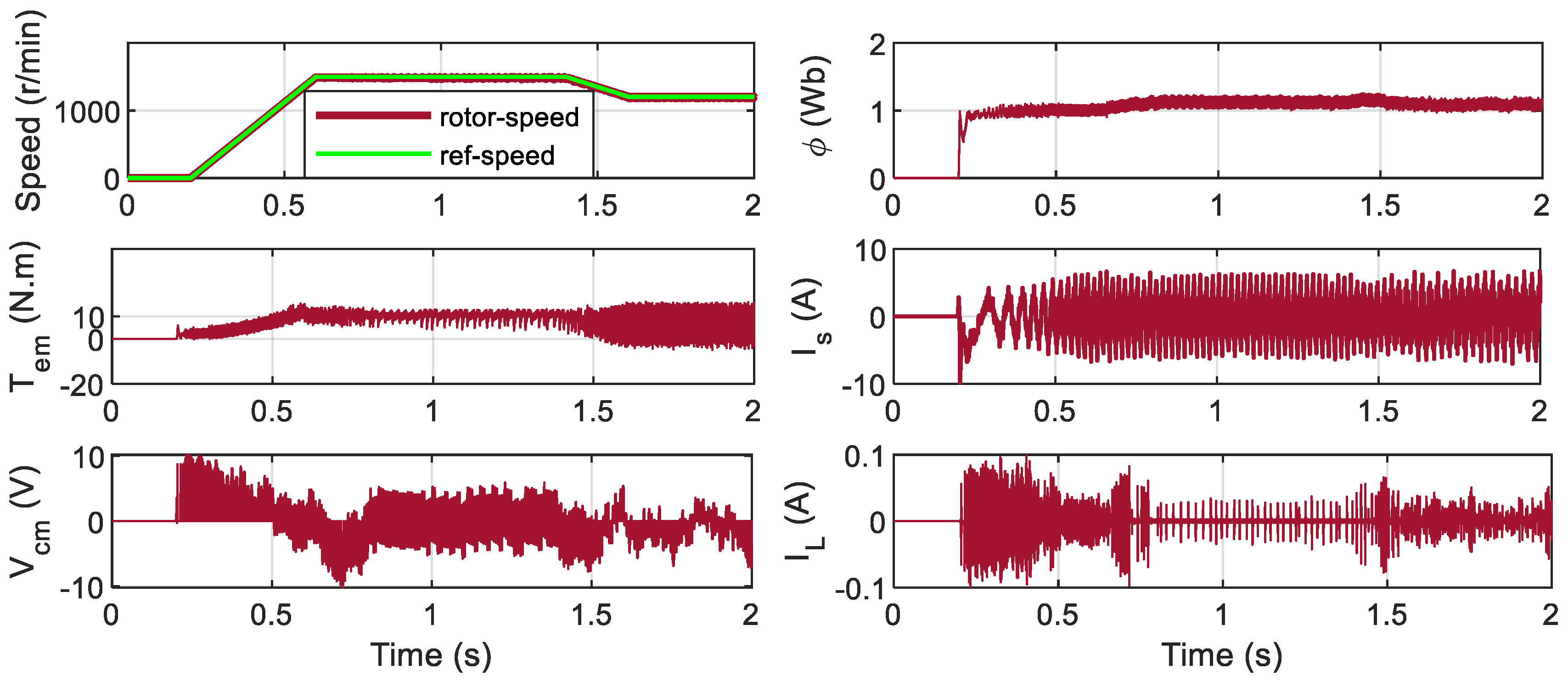
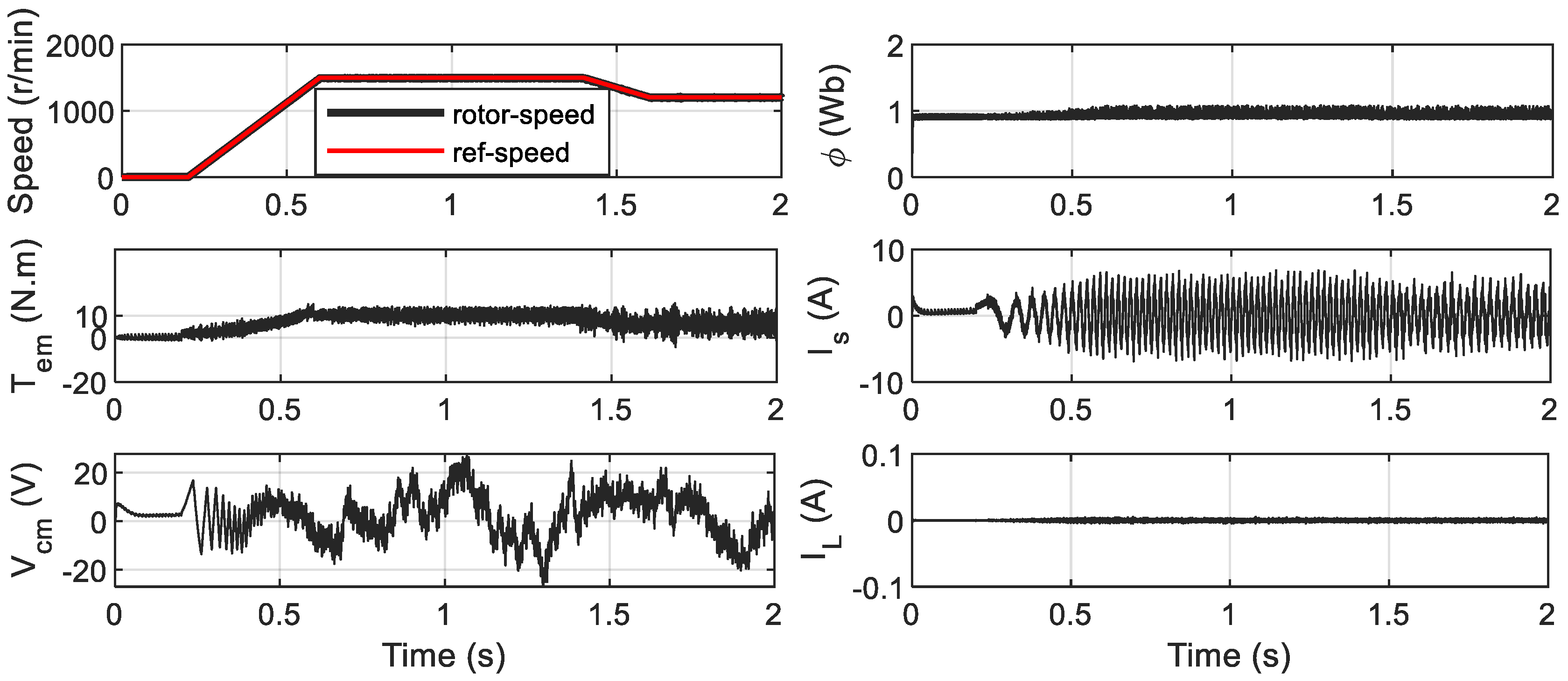
Figure 7, Figure 8 and Figure 9 present the dynamic responses of the two proposed DTC algorithms and the conventional C-DTC under speed variation conditions, considering a pump-type load in which the load torque is proportional to the square of the mechanical speed. The results show that, for all control schemes, the rotor speed closely follows its reference with high accuracy, demonstrating effective speed-tracking capability over the entire operating range.
For all three DTC strategies, the motor successfully tracks both the torque and flux references, but with different levels of ripple. Among them, the C-DTC demonstrates superior performance in terms of torque and flux quality, exhibiting smoother waveforms with minimal ripples. This improvement can be attributed to the use of the full set of voltage vectors, which allows finer control of the stator flux trajectory. Moreover, it can be observed that no overshoots occur during the transient period for the two proposed algorithms, confirming their accurate and stable dynamic performance. In contrast, the proposed algorithms exhibit slightly higher ripple amplitudes due to the intentional elimination of certain voltage vectors aimed at reducing the leakage current. When comparing the two proposed methods, the MV-DTC achieves smoother torque characteristics and comparable flux behavior relative to the ZMV-DTC.
Focusing on the stator current waveform, the current obtained with the C-DTC exhibits superior quality compared to that of the two proposed algorithms. Although a slight degradation in output performance is observed, the proposed methods still preserve the fast dynamic response characteristic of DTC and maintain an overall acceptable performance level. Regarding the obtained CMV, it is evident that the C-DTC strategy generates the largest amplitude variations. The positive and negative peak values reach approximately ±Vdc/6, which occur due to the application of both large and small voltage vectors in each operating sector. In contrast, the ZMV-DTC approach significantly reduces the CMV amplitude variations. This improvement results from the exclusive use of a single zero vector corresponding to the switching state (OOO), combined with six medium voltage vectors distributed across all operating sectors. Furthermore, the MV-DTC algorithm provides the most favorable outcome, where the high-frequency oscillations in the CMV waveform are almost completely eliminated. This enhancement is attributed to the utilization of only medium voltage vectors, which ensures a smoother and more stable CMV profile.
The high amplitude and rapid variations in the CMV generated by C-DTC lead to a significant leakage current, reaching approximately ±2 A. In contrast, the leakage currents produced by the two proposed algorithms are considerably lower, remaining within only a few milliamperes. When comparing the proposed methods, MV-DTC exhibits the best performance, producing an almost negligible leakage current.
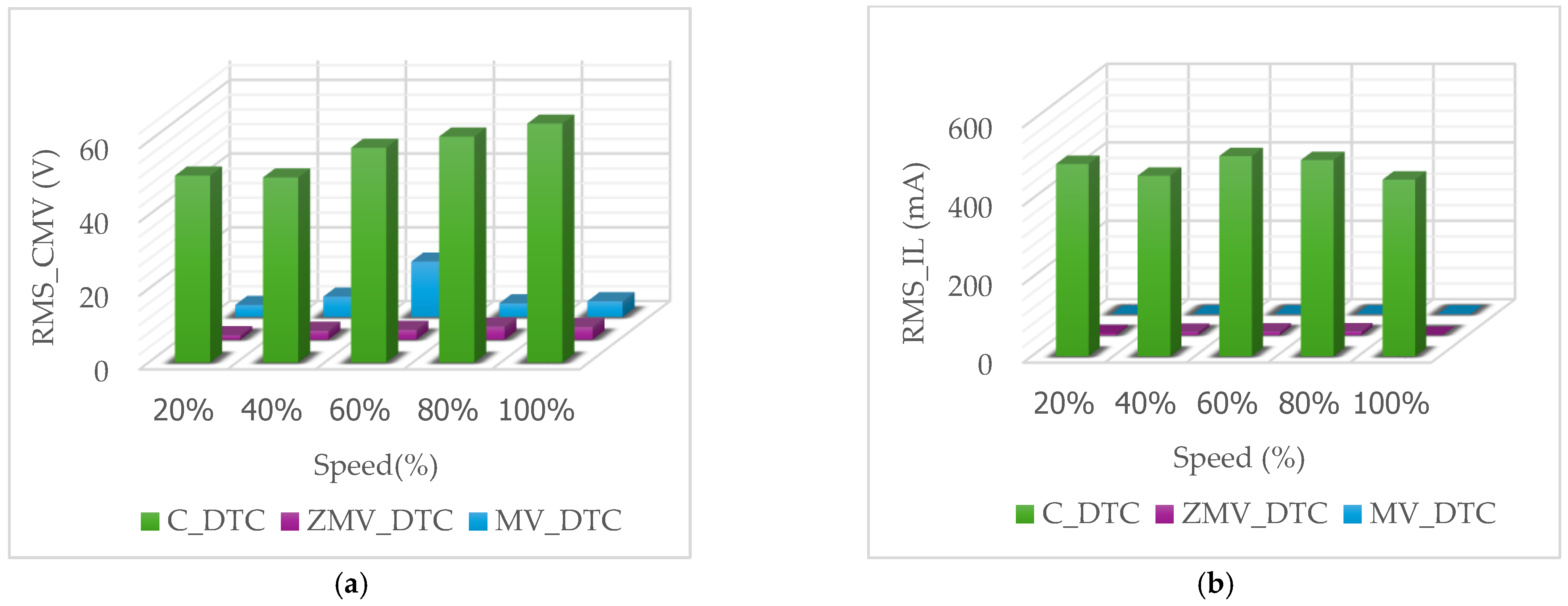
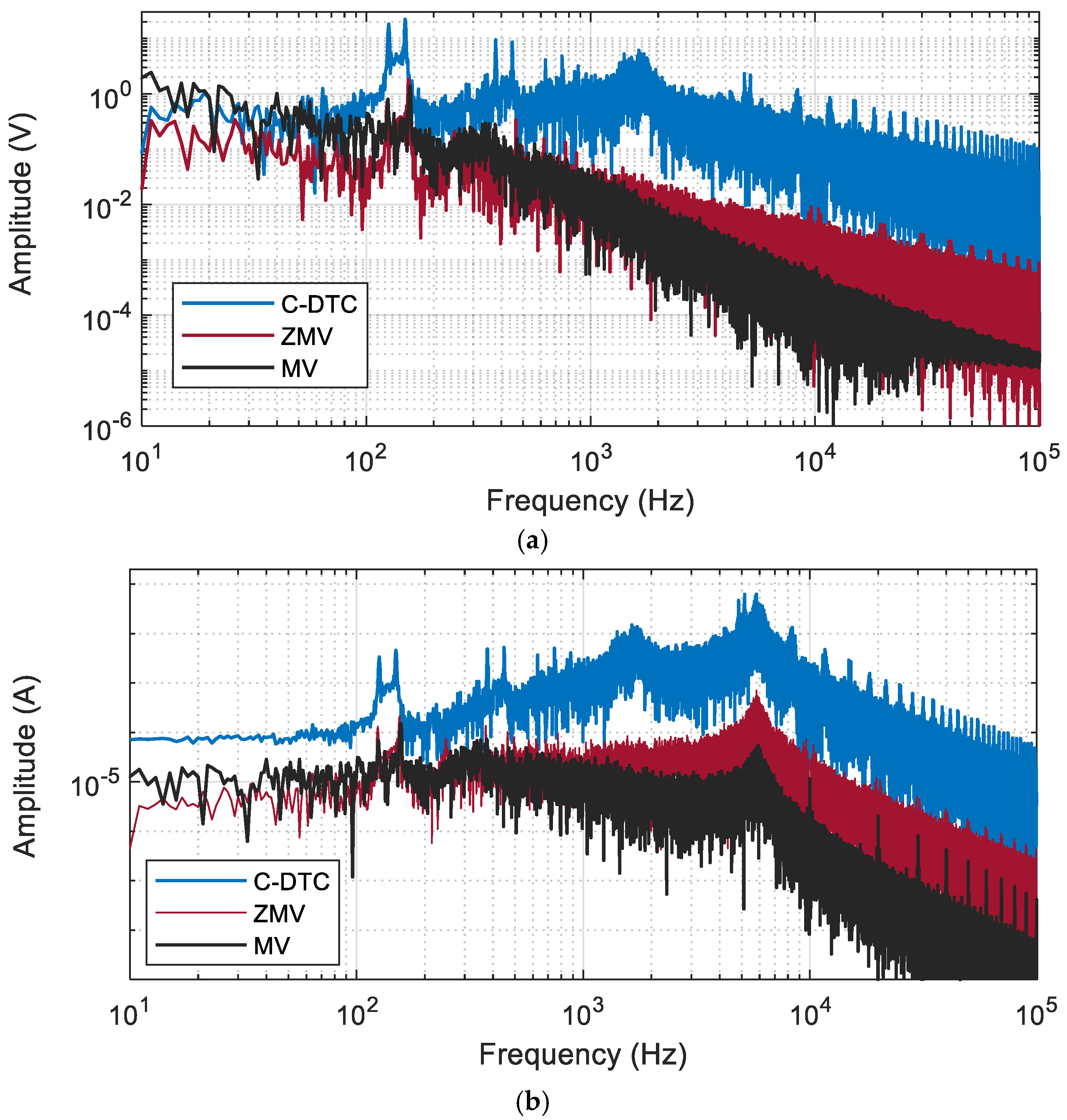
For further analysis, the RMS values of the CMV and leakage current were calculated under varying rotor speed conditions. The results, presented in Figure 10, clearly indicate that C-DTC produces the highest RMS values for both CMV and leakage current. In contrast, the two proposed DTC algorithms generate comparable RMS values for the CMV and effectively suppress the RMS leakage current. Although ZMV-DTC and MV-DTC achieve similar CMV RMS levels, MV-DTC exhibits a lower RMS leakage current. This improvement arises because the leakage current is influenced not only by the CMV amplitude but also by its variations, and MV-DTC, by employing only one type of voltage vector, minimizes fluctuations in the CMV waveform. The frequency-domain spectra of the CMV and the leakage current obtained with the proposed DTC algorithms and the conventional C-DTC are also presented and compared in Figure 11. A visual inspection clearly indicates the superiority of the proposed DTC strategies in mitigating both CMV and leakage current components. In particular, the harmonic amplitudes are significantly reduced and become almost negligible over the analyzed frequency range. This superior performance is quantitatively confirmed by the results summarized in Table 6.
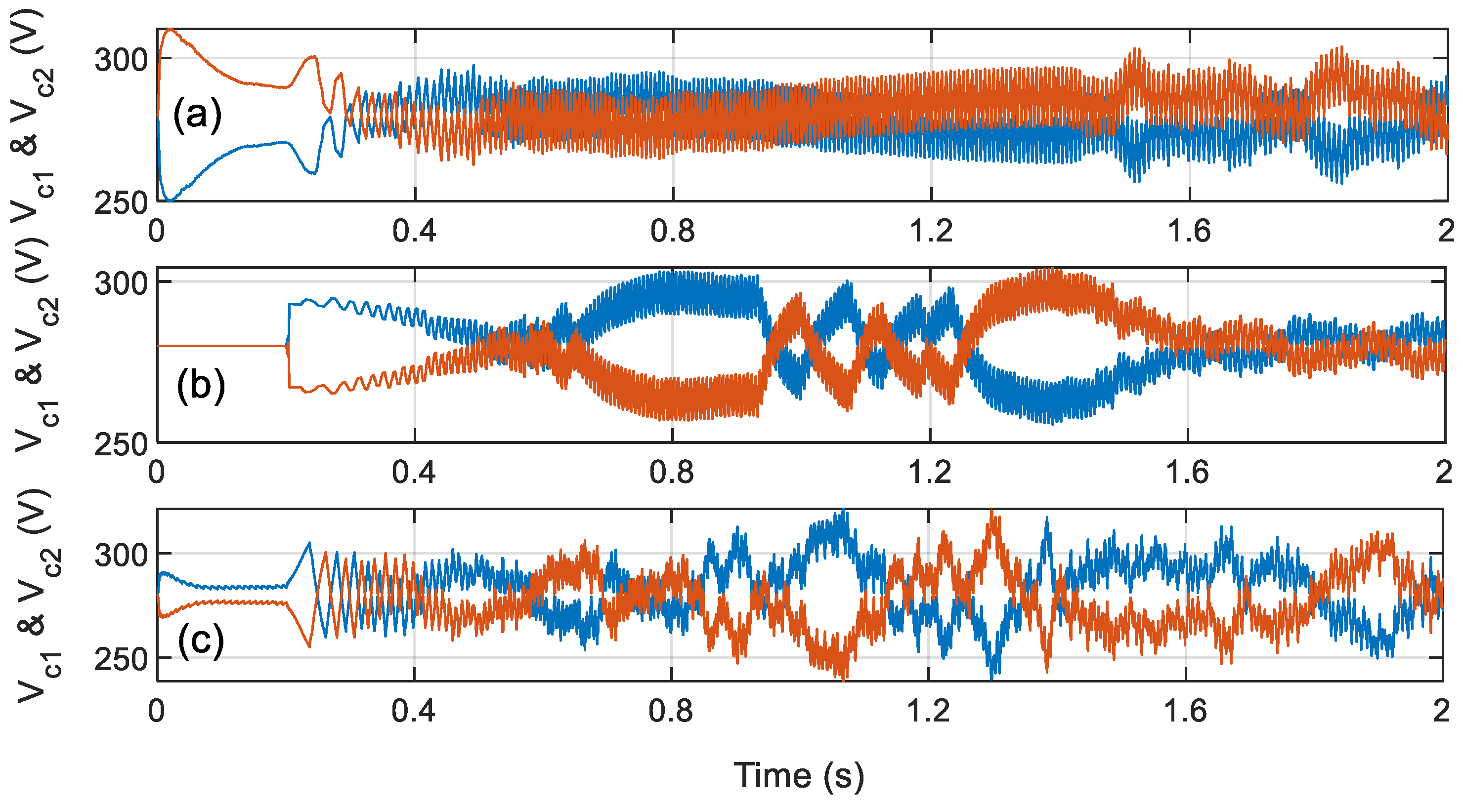
For further comparison, the voltages across the DC-link capacitors are presented in Figure 12. As observed, the obtained results are comparable. Among the evaluated strategies, C-DTC exhibits the best performance in terms of neutral-point voltage (NPV) balancing. The two proposed DTC algorithms also provide acceptable performance, with voltage fluctuations not exceeding approximately 20 V. This behavior can be attributed to the use of medium voltage vectors, which directly influence the midpoint current and thereby contribute to NPV regulation.
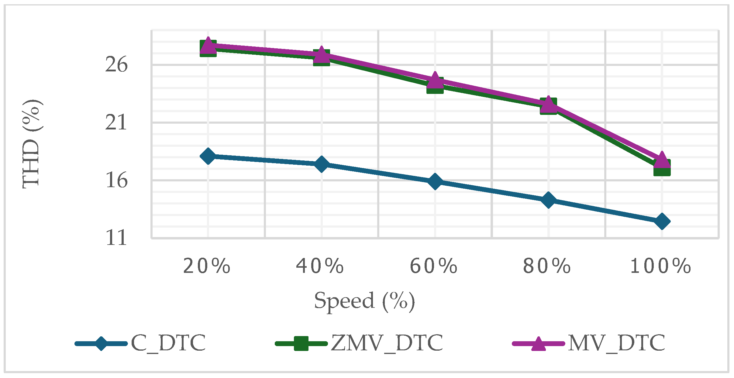
The total harmonic distortion (THD) was evaluated for the studied DTC strategies under varying rotor speed conditions, and the results are presented in Figure 13. C-DTC demonstrates superior performance compared to the proposed methods in terms of THD. This improvement is attributed to the lower fluctuations in flux and torque observed with the C-DTC approach, which helps maintain a cleaner stator current waveform. Furthermore, the two proposed algorithms show approximately similar results.
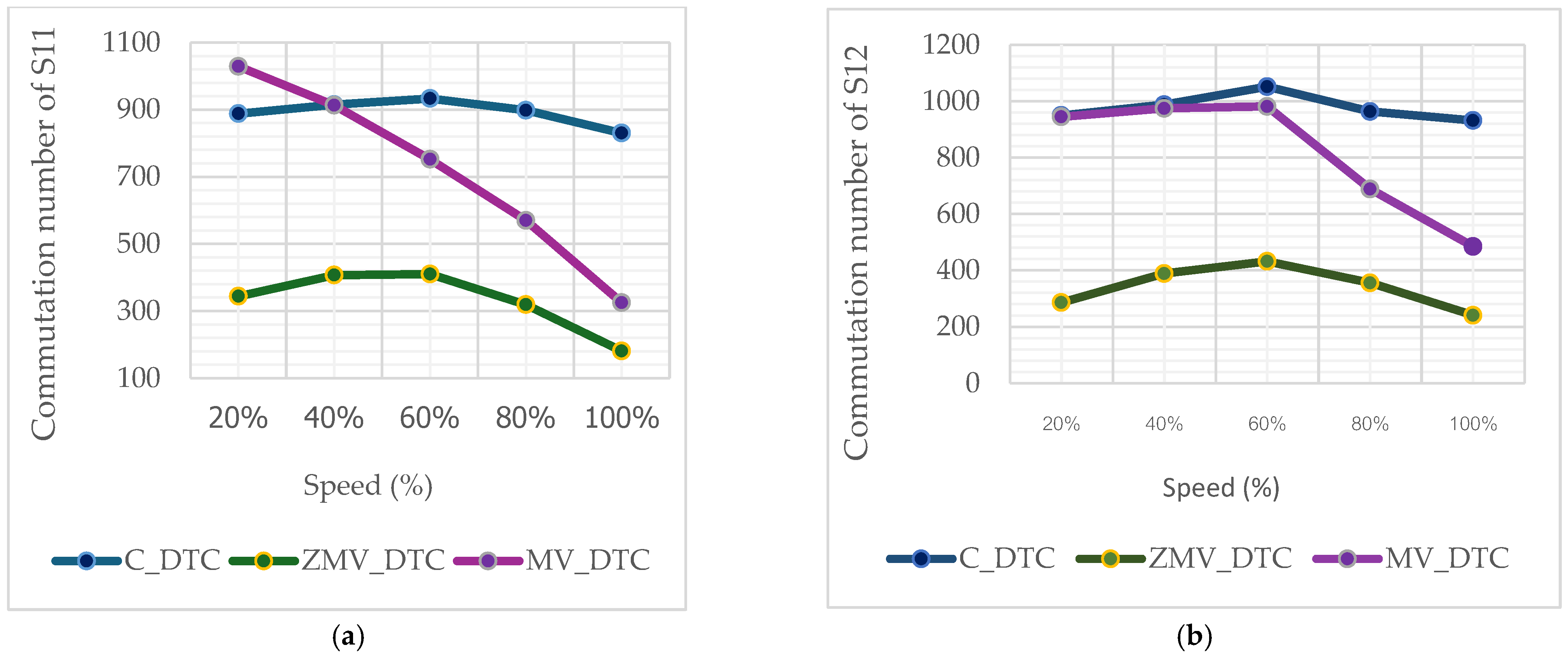
Switching loss is a critical performance criterion in power conversion systems as it directly affects both power dissipation and overall efficiency. To assess this aspect, the number of commutations of switching devices S11 and S12 in phase a was evaluated since it provides a direct and reliable indicator of switching losses. The obtained results, illustrated in Figure 14, clearly show that the proposed DTC algorithms lead to a significant reduction in the number of commutations compared with C-DTC. This reduction confirms their effectiveness in minimizing switching losses. Moreover, when comparing the two proposed strategies, the ZMV-DTC exhibits the lowest commutation count, demonstrating superior performance in terms of switching loss reduction.
The results of torque and stator flux ripples, peak values of CMV, and peak values of leakage current under varying speed conditions are summarized in Table 7. Although the proposed algorithms exhibit increased flux and torque ripples, the table clearly demonstrates their superior performance in terms of CMV and leakage current. Specifically, the proposed DTC methods effectively suppress the leakage current, whereas C-DTC only partially reduces the CMV, leaving the leakage current at relatively high levels.

6. Conclusions

This study presents a safer direct torque control strategy for induction motor drives powered by transformerless multilevel PV inverters, specifically designed for PV pumping applications. The proposed approach aims to suppress leakage currents, thereby enhancing system reliability and safety. Two optimized control algorithms, referred to as ZMV-DTC and MV-DTC, are developed. For each method, a dedicated switching LUT is constructed to regulate the stator flux and electromagnetic torque while minimizing the amplitude variation in the CMV, the primary source of leakage current. Simulation results verify the correct operation of the proposed control schemes and demonstrate that both algorithms outperform the C-DTC in terms of CMV reduction, leakage current mitigation, and switching loss minimization. Notably, the leakage current achieved using the proposed methods remains within a few milliamperes, with the MV-DTC approach providing the most effective suppression. These results confirm the suitability of the proposed strategies for transformerless PV pumping systems, where reliability and safety are of paramount importance. A limitation of the proposed DTC algorithms is that using only medium vectors can reduce the maximum stator-voltage vector under high-speed or field-weakening conditions.

Author Contributions

Conceptualization, Z.B.M.; methodology, Z.B.M.; validation, Z.B.M. and A.K.; formal analysis, Z.B.M.; investigation, Z.B.M.; resources, Z.B.M.; data curation, Z.B.M. and A.K.; writing—original draft preparation, Z.B.M.; writing—review and editing, Z.B.M. and A.K.; supervision, A.K. All authors have read and agreed to the published version of the manuscript.

Funding

This research received no external funding.

Institutional Review Board Statement

Not applicable.

Data Availability Statement

The original contributions presented in this study are included in the article. Further inquiries can be directed to the corresponding author.

Conflicts of Interest

The authors declare no conflicts of interest.

References

  1. Gevorkov, L.; Domínguez-García, J.L.; Romero, L.T. Review on Solar Photovoltaic-Powered Pumping Systems. Energies 2023, 16, 94. [Google Scholar] [CrossRef]
  2. Amri, A.; Moussa, I.; Khedher, A. Design and analysis of a photovoltaic water pumping system for sustainable agricultural irrigation. In Proceedings of the 2025 IEEE 22nd International Multi Conference on Systems, Signals & Devices (SSD), Monastir, Tunisia, 17–20 February 2025. [Google Scholar] [CrossRef]
  3. Poompavai, T.; Kowsalya, M. Control and energy management strategies applied for solar photovoltaic and wind energy fed water pumping system: A review. Renew. Sustain. Energy Rev. 2019, 107, 108–122. [Google Scholar] [CrossRef]
  4. Ahmed, M.M.; Bawayan, H.M.; Enany, M.A.; Elymany, M.M.; Shaier, A.A. Modern advancements of energy storage systems integrated with hybrid renewable energy sources for water pumping application. Eng. Sci. Technol. Int. J. 2025, 62, 101967. [Google Scholar] [CrossRef]
  5. Amri, A.; Moussa, I.; Khedher, A. Design and control of a hybrid water pumping system using energy management for sustainable agricultural irrigation: A case study of the Sidi Bouzid region in Tunisia. Int. J. Renew. Energy Dev. 2025, 14, 1146–1159. [Google Scholar] [CrossRef]
  6. Barrueto Guzmán, A.; Barraza Vicencio, R.; Ardila-Rey, J.A.; Núñez Ahumada, E.; González Araya, A.; Arancibia Moreno, G. A cost-effective methodology for sizing solar PV systems for existing irrigation facilities in Chile. Energies 2018, 11, 1853. [Google Scholar] [CrossRef]
  7. Kumar, R.; Naik, M.V. Enhanced photovoltaic water pumping system employing Kalman filter-based MPPT coupled with multilevel inverter-driven DTC–IM. J. Power Electron. 2025, 26, 201–213. [Google Scholar] [CrossRef]
  8. Saady, I.; Majout, B.; El Kafazi, I.; Karim, M.; Bossoufi, B.; El Ouanjli, N.; Mahfoud, S.; Althobaiti, A.; Alghamdi, T.A.; Alenezi, M. Improving photovoltaic water pumping system performance with ANN-based direct torque control using real-time simulation. Sci. Rep. 2025, 15, 4024. [Google Scholar] [CrossRef]
  9. Abdellahi, B.; Mahmoud, M.E.M.M.; Dah, N.O.; Diakité, A.; El Hassen, A.; Ehssein, C. Monitoring the performances of a maximum power point tracking photovoltaic (MPPT PV) pumping system driven by a brushless direct current (BLDC) motor. Int. J. Renew. Energy Dev. 2019, 8, 193–201. [Google Scholar] [CrossRef]
  10. Ben Mahmoud, Z.; Guenenna, T.; Khedher, A. A novel virtual vector-based direct power control strategy to reduce common mode voltage in transformer-less two-level grid-connected VSI. Electr. Eng. 2025, 107, 121–132. [Google Scholar] [CrossRef]
  11. Balachandran, A.; Jonsson, T.; Eriksson, L. DC Charging Capabilities of Battery-Integrated Modular Multilevel Converters Based on Maximum Tractive Power. Electricity 2023, 4, 62–77. [Google Scholar] [CrossRef]
  12. Ben Mahmoud, Z.; Hamouda, M.; Khedher, A. Direct power control with common mode voltage reduction of grid-connected three-level NPC inverter. IET Power Electron. 2019, 12, 400–409. [Google Scholar] [CrossRef]
  13. Mashayekh, A.; Pohlmann, S.; Estaller, J.; Kuder, M.; Lesnicar, A.; Eckerle, R.; Weyh, T. Multi-Agent Reinforcement Learning-Based Decentralized Controller for Battery Modular Multilevel Inverter Systems. Electricity 2023, 4, 235–252. [Google Scholar] [CrossRef]
  14. Premkumar, M.; Karthick, K.; Sowmya, R. A Review on Solar PV Based Grid Connected Microinverter Control Schemes and Topologies. Int. J. Renew. Energy Dev. 2018, 7, 171–182. [Google Scholar] [CrossRef]
  15. Ben Mahmoud, Z.; Khedher, A. A Comprehensive Review on Space Vector Based-PWM Techniques for Common Mode Voltage Mitigation in Photovoltaic Multi-Level Inverters. Energies 2024, 17, 916. [Google Scholar] [CrossRef]
  16. Jayakumar, V.; Chokkalingam, B.; Munda, J.L. A Comprehensive Review on Space Vector Modulation Techniques for Neutral Point Clamped Multi-Level Inverters. IEEE Access 2021, 9, 112104–112144. [Google Scholar] [CrossRef]
  17. Khan, A.A.; Khan, U.A.; Ahmed, H.F.; Cha, H.; Ahmed, S. Improved NPC Inverters Without Short-Circuit and Dead-Time Issues. IEEE Trans. Power Electron. 2022, 37, 2180–2190. [Google Scholar] [CrossRef]
  18. Li, S.; Wang, W.; Han, X.; Liu, X. A DPWM Modulation Strategy to Reduce Common-Mode Voltage for Indirect Matrix Converters Based on Active-Current Vector Amplitude Characteristics. IEEE Trans. Ind. Electron. 2022, 69, 8102–8112. [Google Scholar] [CrossRef]
  19. Vijeh, M.; Rezanejad, M.; Samadaei, E.; Bertilsson, K.A. General Review of Multilevel Inverters Based on Main Submodules: Structural Point of View. IEEE Trans. Power Electron. 2019, 34, 9479–9502. [Google Scholar] [CrossRef]
  20. Phuyal, S.; Shrestha, S.; Sharma, S.; Subedi, R.; Panjiyar, A.K.; Gautam, M. An Optimized H5 Hysteresis Current Control with Clamped Diodes in Transformer-Less Grid-PV Inverter. Electricity 2025, 6, 1. [Google Scholar] [CrossRef]
  21. Orfanoudakis, G.I.; Koutroulis, E.; Foteinopoulos, G.; Wu, W. Analysis and reduction of common-mode ground leakage current in transformerless PV inverters with rectified sine wave DC-link voltage. J. Power Electron. 2025, 26, 227–241. [Google Scholar] [CrossRef]
  22. Al-Mamoori, D.H.; Shahrin, M.A.; Arif, S.M. Single-stage transformer less multilevel boost inverter with zero leakage current for PV system. Int. J. Power Electron. Drive Syst. 2025, 16, 673~682. [Google Scholar] [CrossRef]
  23. Carvalho, C.C.A.; da Silva, P.R.D.R.; Araújo, J.M.; Pomili, J.A. Leakage Current Mitigation in On-Grid Photovoltaic Systems Using a Flexible Multi-Level Inverter Topology. Eletrônica Potência 2025, 30, e202527. [Google Scholar] [CrossRef]
  24. Xu, W.; Ali, M.M.; Elmorshedy, M.F.; Allam, S.M.; Mu, C. One improved sliding mode DTC for linear induction machines based on linear metro. IEEE Trans. Power Electron. 2021, 36, 4560–4571. [Google Scholar] [CrossRef]
  25. Wu, X.; Huang, W.; Lin, X.; Jiang, W.; Zhao, Y.; Zhu, S. Direct torque control for induction motors based on minimum voltage vector error. IEEE Trans. Ind. Electron. 2021, 68, 3794–3804. [Google Scholar] [CrossRef]
  26. Soyed, A.; Aouiti, A.; Hasnaoui, O.; Bacha, F. SVM-FL-DTC control induction motor drives fed by indirect matrix converter. In Proceedings of the 5th International Conference on Advanced Systems and Emergent Technologies (IC_ASET), Hammamet, Tunisia, 22–25 March 2022; pp. 301–306. [Google Scholar] [CrossRef]
  27. Muduli, U.R.; Chikondra, B.; Behera, R.K. Space Vector PWM Based DTC Scheme with Reduced Common Mode Voltage for Five-Phase Induction Motor Drive. IEEE Trans. Power Electron. 2022, 37, 114–124. [Google Scholar] [CrossRef]
  28. Deng, W.; Li, S. Direct Torque Control of Matrix Converter-Fed PMSM Drives Using Multidimensional Switching Table for Common-Mode Voltage Minimization. IEEE Trans. Power Electron. 2021, 36, 683–690. [Google Scholar] [CrossRef]
  29. Tatte, Y.; Aware, M.; Badoni, M. Modified Direct Torque Control Technique of Induction Motor for Torque Ripple and Common-Mode Voltage Reduction with Neutral-Point Voltage Balancing. Iran J. Sci. Technol. Trans. Electr. Eng. 2022, 46, 1207–1221. [Google Scholar] [CrossRef]
  30. Dewangan, H.; Singh, A.K.; Ratrey, S.D.; Ch, S.P.K.; Venu, S.; Jain, S. Common Mode Voltage Reduction in Space Vector Modulated Direct Torque Controlled Induction Motor Drive. In Proceedings of the 2024 Third International Conference on Power, Control and Computing Technologies (ICPC2T), Raipur, India, 18–20 January 2024; pp. 829–833. [Google Scholar] [CrossRef]
  31. Bhowate, A.; Aware, M. CMV suppression using a new predictive direct torque control for induction motor. In Proceedings of the 2016 7th India International Conference on Power Electronics (IICPE), Patiala, India, 17–19 November 2016; pp. 1–6. [Google Scholar] [CrossRef]
  32. Tatte, Y.; Aware, M. Twelve sectors direct torque control for three-level inverter fed induction motor drive. Electr. Eng. 2025, 107, 6107–6121. [Google Scholar] [CrossRef]
  33. Boudallaa, A.; Belkhadir, A.; Chennani, M.; Belkhayat, D.; Zidani, Y.; Rhofir, K. Real-Time Implementation of Sensorless DTC-SVM Applied to 4WDEV Using the MRAS Estimator. Energies 2023, 16, 7090. [Google Scholar] [CrossRef]
  34. Benayad, A.; Gasbaoui, B.; Bentouba, S.; Soumeur, M.A. Movement of a Solar Electric Vehicle Controlled by ANN-based DTC in Hot Climate Regions. Int. J. Renew. Energy Dev. 2021, 10, 61–70. [Google Scholar] [CrossRef]
  35. Patil, R.B.; Khalkar, A.; Al-Dahidi, S.; Pimpalkar, R.S.; Bhandari, S.; Pecht, M. A Reliability and Risk Assessment of Solar Photovoltaic Panels Using a Failure Mode and Effects Analysis Approach: A Case Study. Sustainability 2024, 16, 4183. [Google Scholar] [CrossRef]
  36. Wang, L.; He, J.; Chenyu, Z. Closed Loop Multi-Path Common Mode Circulating Currents Mitigation in Paralleled Transformerless Soft Open Points. IEEE Trans. Power Electron. 2025, 41, 5328–5341. [Google Scholar] [CrossRef]
  37. Ben Mahmoud, Z.; Khedher, A. FPGA-based implementation of an enhanced space vector modulation algorithm that reduces the common mode voltage in three-level NPC inverter through the synthesis of a virtual zero-vector in the two-level hexagon. Electr. Eng. 2025, 107, 10841–10854. [Google Scholar] [CrossRef]
  38. Tatte, Y.N.; Aware, M.V. Direct Torque Control of Induction Motor with Common-Mode Voltage Elimination. Electr. Power Compon. Syst. 2016, 44, 2310–2324. [Google Scholar] [CrossRef]
Figure 1. General overview of a PV pumping system based on a multilevel inverter.
Electricity 07 00019 g001
Figure 2. Methods dedicated to CMV reduction in DTC schemes.
Electricity 07 00019 g002
Figure 4. Leakage current path in PV three-level NPC inverter coupled with IM.
Electricity 07 00019 g004
Figure 5. Synoptic diagram of the proposed DTC algorithms.
Electricity 07 00019 g005
Figure 6. Space vector selection in sector 1: (a) ZMV-DTC; (b) MV-DTC.
Electricity 07 00019 g006
Figure 7. Obtained dynamic performance results of C-DTC.
Electricity 07 00019 g007
Figure 8. Obtained dynamic performance results of ZMV-DTC.
Electricity 07 00019 g008
Figure 9. Obtained dynamic performance results of MV-DTC.
Electricity 07 00019 g009
Figure 10. Comparison of RMS values: (a) CMV; (b) leakage current.
Electricity 07 00019 g010
Figure 11. Frequency spectra of (a) CMV and (b) leakage current.
Electricity 07 00019 g011
Figure 12. DC-link capacitor voltage waveforms: (a) C-DTC, (b) ZMV-DTC, and (c) MV-DTC.
Electricity 07 00019 g012
Figure 13. THD comparison.
Electricity 07 00019 g013
Figure 14. Comparison of commutation numbers: (a) S11 and (b) S12.
Electricity 07 00019 g014
Table 3. Look-up table of ZMV-DTC.
STSFS1S2S3S4S5S6S7S8S9S10S11S12
00 V ¯ 0 V ¯ 0 V ¯ 0 V ¯ 0 V ¯ 0 V ¯ 0 V ¯ 0 V ¯ 0 V ¯ 0 V ¯ 0 V ¯ 0 V ¯ 0
01 V ¯ 0 V ¯ 0 V ¯ 0 V ¯ 0 V ¯ 0 V ¯ 0 V ¯ 0 V ¯ 0 V ¯ 0 V ¯ 0 V ¯ 0 V ¯ 0
10 V ¯ 10 V ¯ 12 V ¯ 12 V ¯ 14 V ¯ 14 V ¯ 16 V ¯ 16 V ¯ 18 V ¯ 18 V ¯ 8 V ¯ 8 V ¯ 10
11 V ¯ 8 V ¯ 8 V ¯ 10 V ¯ 10 V ¯ 12 V ¯ 12 V ¯ 14 V ¯ 14 V ¯ 16 V ¯ 16 V ¯ 18 V ¯ 18
Table 4. Look-up table of MV-DTC.
STSFS1S2S3S4S5S6S7S8S9S10S11S12
00 V ¯ 12 V ¯ 14 V ¯ 14 V ¯ 16 V ¯ 16 V ¯ 18 V ¯ 18 V ¯ 8 V ¯ 8 V ¯ 10 V ¯ 10 V ¯ 12
01 V ¯ 18 V ¯ 8 V ¯ 8 V ¯ 10 V ¯ 10 V ¯ 12 V ¯ 12 V ¯ 14 V ¯ 14 V ¯ 16 V ¯ 16 V ¯ 18
10 V ¯ 10 V ¯ 12 V ¯ 12 V ¯ 14 V ¯ 14 V ¯ 16 V ¯ 16 V ¯ 18 V ¯ 18 V ¯ 8 V ¯ 8 V ¯ 10
11 V ¯ 8 V ¯ 10 V ¯ 10 V ¯ 12 V ¯ 12 V ¯ 14 V ¯ 14 V ¯ 16 V ¯ 16 V ¯ 18 V ¯ 18 V ¯ 8
Table 5. Parameters of the conversion system and IM.
ParameterValueParameterValue
DC bus voltage560 VRated torque10 N·m
Sampling time100 µsRated Flux0.91 Wb
DC-bus capacitor470 μFNumber of pole pairs2
Rated power1.5 kWStator resistance5.72 Ω
Rated speed1435 r/minRotor resistance4.28 Ω
Rated current5.5/3.2 AStator and rotor inductances0.464 H
Rated voltage560 VMutual inductance0.44 H
Moment of inertia0.0049 kg·m2Viscous friction coefficient0.002
Hysteresis bandsHT = 0.1 N·m; HF = 0.001 WbPI controller parametersKp = 3.4;
ki = 0.15
Table 6. The most important amplitudes of the harmonics in CMV and leakage current.
Harmonics in CMVHarmonics in Leakage Current
Frequency (Hz)C-DTCZMV-DTCMV-DTCFrequency (Hz)C-DTCZMV-DTCMV-DTC
15022.30 V1.80 V1.38 V4505.2 mA0.091 mA0.022 mA
4508.56 V0.34 V0.13 V7505.0 mA0.092 mA0.025 mA
7504.80 V0.13 V0.06 V500062.4 mA0.7 mA0.053 mA
Table 7. Performance comparison of the studied DTC schemes.
DTC ApproachSpeed Variation (%)20406080100
C-DTCTorque ripple (Nm)2.033.052.512.832.45
Flux ripple (Wb)0.0750.0750.0750.0650.073
CMV peak values (V)±100±100±100±100±100
IL peak values (mA)±300±300±200±200±200
ZMV-DTCTorque ripple (Nm)4.475.225.154.931.57
Flux ripple (Wb)0.1030.1140.1130.1250.082
CMV peak values (V)±10±10±10±8±8
IL peak values (mA)±60±50±100±50±50
MV-DTCTorque ripple (Nm)5.716.326.685.023.69
Flux ripple (Wb)0.1270.1320.1500.1470.150
CMV peak values (V)±20±20±20±20±20
IL peak values (mA)±2±4±4±5±5
Disclaimer/Publisher’s Note: The statements, opinions and data contained in all publications are solely those of the individual author(s) and contributor(s) and not of MDPI and/or the editor(s). MDPI and/or the editor(s) disclaim responsibility for any injury to people or property resulting from any ideas, methods, instructions or products referred to in the content.