
Proceeding Paper

Injection Mould Design for Biopolymer Composite Flow Analysis †

by
Jibrilla Abdulrahman
1,*,
Williams S. Ebhota
2 and
Pavel Y. Tabakov
1,2
1
Mechanical Engineering Department, Durban University of Technology, Durban 4001, South Africa
2
Institute of Systems Science, Durban University of Technology, Durban 4001, South Africa
*
Author to whom correspondence should be addressed.
Presented at the 4th International Conference on Applied Research and Engineering, Pretoria, South Africa, 21–23 November 2025.
Mater. Proc. 2026, 31(1), 33; https://doi.org/10.3390/materproc2026031033

Published: 15 May 2026
(This article belongs to the Proceedings of The 4th International Conference on Applied Research and Engineering)

Abstract

Ensuring that the mould design is compatible with the properties of biopolymers can be challenging, as biopolymers often exhibit different flow characteristics compared to traditional plastics. Selecting appropriate injection pressure and production temperature is essential to prevent common defects such as short shot or fibre degradation. Fundamental design elements such as mould material, number of cavities, and cavity layout are frequently overlooked during 3D modelling considerations. This paper presents an approach to the design and injection mould simulation for biopolymer composite processing, using a fixed volume fraction of 70:30 of high-density polyethylene and banana fibre as reinforcement. The study employs SolidWorks software 2024 for both the 3D mould design of the test specimens and the simulation of plastic injection performance. Simulation results show an injection pressure of 75 MPa and a melt temperature of 200 °C, demonstrating complete cavity filling when using a round runner and gate design. This approach enables manufacturers to optimize the injection moulding process, reduce material waste, and ensure the consistent production of high-quality biopolymer composite parts, ultimately improving both efficiency and cost-effectiveness in manufacturing.

1. Introduction

Numerous conventional manufacturing technologies are employed in the production of polymer composites, including injection moulding, pultrusion, fibre drawing, film blowing, compression moulding, thermoforming, extrusion, resin transfer moulding, as well as hand lay-up and spray-up techniques [1,2]. Additionally, advanced manufacturing technologies such as additive manufacturing (3D printing) are increasingly used due to their versatility and relative cost-effectiveness in producing a wide range of polymeric materials [3]. Among the conventional processes, extrusion, injection moulding, and compression moulding are commonly applied for the fabrication of short fibre-reinforced composites. Fu et al. [4] have highlighted notable challenges in processing newly developed composite materials. They recommend modifying existing methods and exploring alternative techniques to enhance production efficiency and improve the quality of the final products. The utilization of advanced technological tools highlights their effective integration for the practical production of composite parts [5]. Amran et al [6] utilized SolidWorks Plastics simulation to analyze a new component design. This approach allowed the authors to identify and resolve design flaws, resulting in a defect-free product. This not only ensured quality but also minimized material waste and improved overall manufacturing efficiency. Moreover, advancements in design methodologies have made it possible to manufacture long fibre-reinforced polymer composites without fibre breakage during processing [7]. Injection moulding, which is one of the most widely used polymer processing techniques, typically requires little to no post-processing. It is also considered cost-effective and time-efficient compared to many other manufacturing methods [8,9,10].
The quality of injection-moulded plastic components is influenced by several factors, including the material selection, component design, mould design, and manufacturing conditions [11]. This research follows established principles, guidelines, literature, and relevant standards to inform the selection of materials, mould design, and processing parameters for injection moulding. SolidWorks will be used to design the 3D geometry of the core and cavity for the mould. Additionally, SolidWorks Plastics will be employed to simulate and optimize the part design to ensure defect-free manufacturing during the injection moulding process. The proposed mould is a two-plate system featuring a single parting line and two cavities, each equipped with a single gate. The design data and simulation results will guide the production of polymer composite samples for experimental testing.

2. Effect of Production Parameters on Polymer Composite

The production of composite materials is highly influenced by the type of materials used and the processing parameters, particularly in injection moulding, where factors such as temperature, injection pressure, injection speed, and holding time play critical roles [12]. Vasiliev and Morozov [13] stated that it is essential that specimens intended for mechanical property evaluation are manufactured using the same processing method that will be applied to the actual structural components under investigation. According to Binqi et al. [14], clamping force is a vital element of the injection moulding process, as product quality is directly affected by the load on the tie bars. Additionally, parameters such as holding time, injection pressure, and barrel temperature significantly impact the mechanical performance of the final product. Therefore, optimizing these parameters is crucial to achieve the desired material properties [12]. Xavier, Tyagi, and Misra [15] reported that a strong bond between the fibre and polymer matrix can be achieved with a back pressure of 700 kg/cm2, which facilitates a homogeneous and ideal flow. They recommend a screw speed between 50 and 100 rpm, noting that speeds below 50 rpm should be avoided, as they extend the cycle time unnecessarily. Bhaskar et al. [16] observed fibre length reduction during the mixing operation. Further reduction in fibre length could also occur during compounding. Chen et al. [17] also suggested that excessive packing pressure and injection speed should be avoided, as they can increase residual stresses and subsequently reduce the mechanical strength of the component. Conversely, higher melt and mould temperatures help to reduce residual stress, thereby improving part quality. However, it is crucial to avoid temperatures exceeding 240 °C, as this threshold can lead to fibre degradation. Natural fibres start to degrade when exposed to such elevated temperatures [18]. This degradation not only compromises the integrity of the fibres but can also affect the overall performance of the material. Srinivasan et al. [18] observed the deterioration of the strength of biopolymer reinforced composites at high temperatures due to the degradation of the natural fibres. To enhance material flow within the cavity during processing, Bhaskar et al. [16] suggested raising the barrel temperature by an additional 10 to 30 °C compared to what is typically used for unreinforced thermoplastics. This adjustment compensates for the higher melt viscosity of reinforced materials, ensuring better flow and more efficient processing.

3. Materials and Methods

3.1. Material Selection

Fracture toughness is a critical mechanical property for evaluating fatigue specimens. High-density polyethylene (HDPE) resins are widely regarded as suitable for rigid applications due to their high toughness, good strength, and ease of processing using processes like injection moulding [19]. The selection of HDPE as the matrix material in this study is based on these favourable properties. The composite formulation consists of 70% HDPE and 30% banana fibre particles measuring 65 µm.

3.2. Part Design

SolidWorks 2024 mould tools are used in the design process, from 2D modelling to the final product. Figure 1a presents the 2D dimensions (mm) derived from ASTM D638 [20], which are used to create the 3D model, while Figure 1b illustrates the corresponding mould cavity design. Moldflow simulation available in SolidWorks helps identify potential problems such as uneven flow, weld line issues, and air traps [21]. Avoiding these defects starts at the part design stage. Careful attention must be given to maintaining uniform wall thickness and accurate overall dimensions, as the quality of moulded parts is critical to their functional performance and is influenced by both mould design and processing parameters [22,23]. Although SolidWorks mould tools offer a degree of automation, adherence to fundamental design principles is essential to ensure a successful and functional mould design.

3.2.1. Wall Thickness

Wall thickness plays a critical role in determining the quality of injection-moulded specimens. If not properly considered, it can lead to defects such as warpage, weld lines, voids, sink marks, and short shots [24]. These issues often arise due to the high thermal expansion of plastics, where thicker sections shrink more than thinner ones, resulting in warpage or sink marks. Park et al. [25] observed that voids tend to form in thicker or curved sections due to restricted material flow. Similarly, walls that are too thin may not receive adequate material flow, leading to structural defects like those found in overly thick walls. Therefore, Melito [26] considered maintaining wall thickness within the recommended range to be essential.
Typically, the wall thickness of injection-moulded parts should range from 2 mm to 4 mm [27]. HCL Technologies [28] noted that walls thicker for reinforced plastics should not be more than 3.0 mm, as high thickness can significantly increase cycle times and the likelihood of void formation. To avoid such issues, it is recommended to maintain uniform wall thickness. If variation is unavoidable, the transition between wall sections should be gradual and kept within 40% to 60% of the adjacent wall thickness for the selected material. Patcharaphun and Jariyatammanukul [29] emphasized that accounting for both fibre orientation and part thickness in design data enables more accurate prediction of the mechanical performance of thermoplastic composites under load. Avoiding overly thick sections reduces the risk of void formation, which can act as crack initiation points and negatively affect the fatigue performance of the specimen.

3.2.2. Draft and Radii

Draft angles facilitate the release of moulded parts by minimizing drag on the part’s surface, as the material tends to shrink onto the core during cooling. Insufficient draft requires additional ejection force, which can lead to part damage or surface defects. Radii are also essential in mould design to optimize material flow, enhance component integrity, and eliminate sharp corners. Sharp edges hinder plastic flow and act as stress concentration points, potentially compromising part strength [22]. It is widely recommended that radii should be approximately 25% of the nominal wall thickness minimum, with external and internal radii ideally set at 1.5 t and 0.5 t, respectively, where t is the wall thickness of the material [30]. Additionally, the design of the ejection system is influenced by factors such as draft angles [31]. A draft angle between 1° and 5° is generally acceptable; however, the greater the thermal shrinkage of the plastic, the larger the required draft angle [32]. Simulation tools are valuable in identifying surfaces lacking sufficient draft or where draft angles have been omitted, thereby helping to ensure proper material flow and complete cavity filling around curved or complex regions [33].

3.2.3. Mould Material

Steel has traditionally been the material of choice for mould manufacturing due to its excellent mechanical properties, including wear resistance, high compressive strength, and chemical stability [34]. Other materials, such as mild steel, aluminum, and composites, are also commonly used. According to Ebhota and Inambao [35], low-carbon mild steel is suitable for small-scale production or smaller moulds because of its good machinability and wide availability. However, proper heat and surface treatments are essential to enhance its performance. The primary goal of material selection is to balance cost-effectiveness with customer requirements and performance objectives [36]. In line with this, mild steel is commonly used to fabricate the mould with subsequent heat treatment to improve the mechanical properties and extend the service life of the mould.

3.2.4. Number of Cavities

There are two widely used methods for determining the number of cavities in mould design: based on the injection pressure or the shot capacity of the injection moulding machine [37]. The shot size refers to the maximum volume of melt that the injection moulding machine can deliver in a single shot, as given in [37].
N = 0.8 V m a x V p
where
Vmax is the shot size of the injection moulding machine;
Vp is the volume of a single product and gate, runner, sprue;
Shot Capacity: Vmax = swept volume × c × Density;
c = 0.92 for amorphous materials;
c = 0.82 for the crystalline materials.
Huang et al. [38] reported that for plastic items requiring high dimensional accuracy, the recommended number of cavities should not exceed four. To ensure product quality, the layout design for multiple cavities must be balanced so that all cavities fill simultaneously. Mould cavities are typically constructed in both even and odd numbers, such as 2, 4, 6, 8, 12, 16, 24, 32, 48, 64, 96, and 128 for even numbers, and 3, 5, 7, and 9 for odd numbers. These are usually arranged in rectangular and circular patterns, respectively [39].

3.2.5. Runner Design

A runner is the channel through which molten plastic is transported from the injection machine nozzle into the mould cavities. There are two main types of runners: cold runners and hot runners. Hot runners are typically used for manufacturing large-sized plastic parts or for high-volume production involving multiple cavities. In contrast, cold runners are more suitable for simpler designs, such as moulds with two cavities [40]. To minimize material waste at the end of the process due to excess cavity volume, Solanki, Singh, and Sheorey [41] emphasized the importance of maximizing the cavity surface area to reduce leftover material after moulding. The simplest mould design from a runner perspective is the single-cavity, single-face mould. This design can also be extended to multi-cavity layouts [42]. In multi-cavity moulds, the runner system must distribute the molten plastic evenly to each cavity to ensure uniform quality in all moulded parts [43]. For polyethylene, the recommended initial runner diameter ranges from 1.6 mm to 9.6 mm. The diameter of secondary runners can be calculated using the equation provided below [44].
D = d N 1 3
d = D N 1 3
where N is the number of branch runners, D is the main runner diameter, and d is the branch runner.
Geometrically balanced multi-cavity moulds do not always guarantee uniform filling. Uneven or asymmetrical filling should be avoided, as it can lead to defects in the moulded parts, potentially compromising their performance and leading to failure [45].

3.2.6. Gate Location

The flow of melt within the mould cavity is strongly influenced by the position of the gate, which significantly affects the moulding quality of the part. Gate location directly impacts fibre orientation and the warpage of the plastic part after moulding [46]. Both the size and shape of the gate are critical factors that influence part quality. The primary function of the gate is to control the flow of material into the component during the filling and packing stages [47]. The most commonly used gate designs include the edge gate, hot tip gate, and sub gate. The edge gate, located at the edge of the mould, is widely applied in flat parts and moulds with multiple cavities [48]. In gate design, the gate should be positioned where the melt enters the thickest section of the cavity and then flows toward the narrower regions [28]. The gate length should generally not exceed 1 mm. For reinforced materials, the recommended gate width or diameter ranges from 0.5 mm to 2.5 mm to prevent premature cooling and surface defects [48]. To ensure balanced flow into each cavity, gate placement, runner cross-section, and runner length should be optimized using computerized mould-filling simulation analysis [49]. For complete cavity filling when using edge gates, the gate land should be smaller than the part thickness [50]. Additionally, the gating system influences fibre orientation as the fibres are subjected to load during the melt flow. The appropriate gate width can be determined using the equation below [49,51].
W = n × A 30
where W is the gate width (sq. inch), n is a material constant, and A is the surface area of the cavity (sq. inch).

3.3. Mould Design

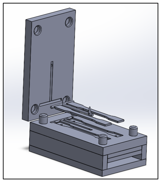
Injection moulding is the most common method for producing plastic components. However, due to its complexity, product designers must account for various factors to ensure optimal moulding performance. This includes minimizing stress concentrations, reducing shrinkage, and producing warp-free parts. Adhering to mouldability standards for plastic components is essential to avoid production issues and ensure high-quality outcomes [28]. Kazmer [52] observed that inadequate mould design often results in low-quality parts or components requiring extensive rework, which can be both time-consuming and costly. The use of computer-aided simulation to model and simulate mould filling behaviour significantly enhances the mould development process to obtain optimum production parameters [53]. Key factors such as part geometry, mould design, material selection, and processing conditions directly influence component quality. To minimize defects such as sink marks, shrinkage, warpage, weld lines, and air traps, these variables must be thoroughly considered during the mould design stage [41]. Based on the 2D part dimensions and 3D model (shown in Figure 1a,b), 3D mould was modelled in SolidWorks 2024 to generate the core and cavity geometry for subsequent plastic flow simulation and analysis. The above design considerations of injection moulding design were considered in the design of the mould shown in Figure 2.

3.4. Cavity Simulation

SolidWorks Plastics simulation analyzes injection moulds and plastic components by modelling the flow of molten plastic during the injection moulding process. This helps predict manufacturing defects, evaluate part manufacturability, improve quality, and eliminate costly rework [54]. Additionally, this CAE tool can forecast the location and severity of defects, providing a reliable and efficient means of producing high-quality castings [55]. Mould flow simulations were performed for a two-cavity mould based on a 3D dog-bone specimen model. The purpose of the simulation was to determine the production parameters for the injection moulding process. A commonly used plastic material, HDPE, was selected from the default material library of the software. However, the properties of the treated plantain fibre were added as a new material to the software library to enable composite analysis based on the injection-moulding process settings and the polymer database. All required material parameters were entered in the appropriate fields within the polymer material’s property manager to ensure accurate simulation and analysis. To investigate the plastic flow behaviour, an analysis was conducted using 65 µm particle size and a volume fraction of 70:30 for banana fibre and HDPE, respectively, as shown in Table 1.

3.5. Sample Production

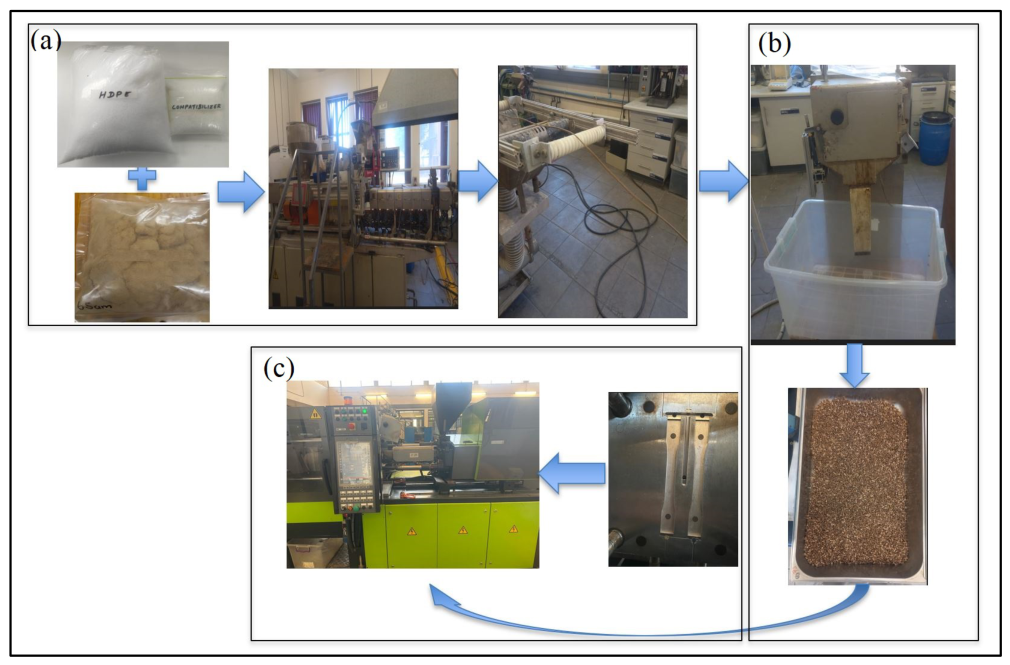
Banana fibre particles of 65 μm and a high-density polyethylene (HDPE) matrix were compounded at a volume fraction of 30:70, with the addition of 3 wt.% compatibilizer. The mixtures were compounded as shown in Figure 3a using an extrusion machine at a temperature range of 120–200 °C, a feed rate of 6.6 kg h−1, a screw speed of 124 rpm, and a pressure of 2.9 MPa. The extruded filaments were subsequently pelletized as illustrated in Figure 3b to improve processability and to obtain a uniform feedstock suitable for injection moulding. Standard dog-bone specimens were produced using an injection moulding machine at a melt temperature of 200 °C, an injection pressure of 75 MPa, and a holding time of 15 s. Figure 3c below shows the production of the sample using the injection moulding machine.

4. Results and Discussion

4.1. Draft Analysis

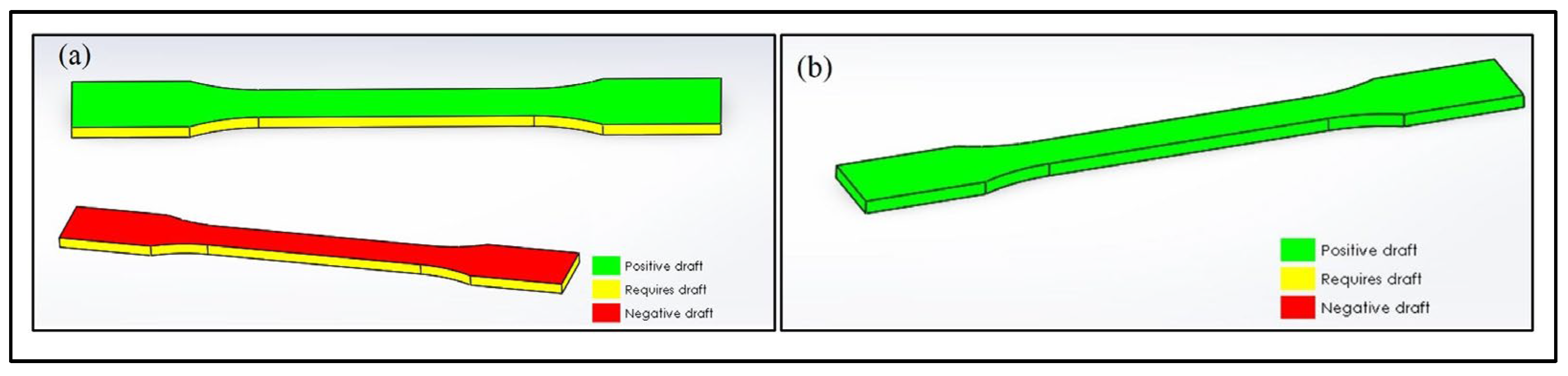
A draft analysis was performed to evaluate the ease with which the specimen can be ejected from the mould after production. This assessment considered key factors such as wall thickness, fillet radius, and draft angle. As shown in Figure 4a, the yellow-coloured regions highlight areas that require an appropriate draft angle to ensure smooth ejection. The analysis indicated that a 5-degree draft angle applied is sufficient for the part to be ejected without difficulty, thereby maintaining the quality and integrity of the specimen, as illustrated in Figure 4b. Evaluating the ejection process at the design stage is essential, as it helps identify and address potential issues before actual manufacturing begins.

4.2. Flow Analysis

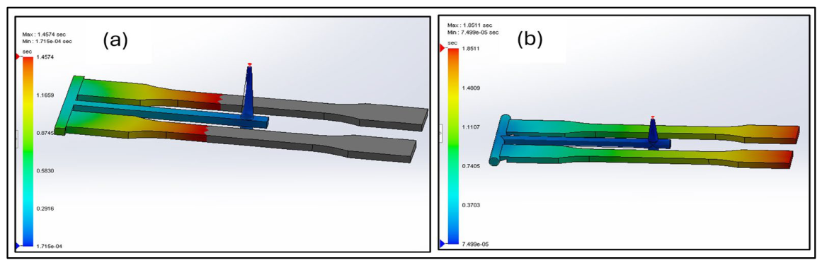
The results of subsequent analyses are highly dependent on the proper filling of the mould cavities. If the parts are not filled with material, the analysis will automatically abort, and no further simulation can proceed. This issue was encountered during the simulation of a rectangular runner, where a short shot was noted, which might be because of the difficulty of the flow of fibre around the corners. This occurred due to incomplete filling of the cavities. In this scenario, only some parts of the cavity were properly filled, while the remaining portion was unfilled, as shown in Figure 5a. This issue could potentially be addressed by adjusting the specimen thickness or increasing the injection pressure; the thickness had already been set based on recommended guidelines. To resolve this, a round runner system was adopted for analysis. The results of the plastic flow simulation using the round runner and gating system showed complete cavity filling without any short shots, as illustrated in Figure 5b. This indicates a high level of fill and demonstrates the feasibility of successfully filling the cavity with the current settings. The filling analysis figures also illustrate the flow profile of the plastic melt as it travels through the cavity during the injection phase.

4.3. Temperature Analysis

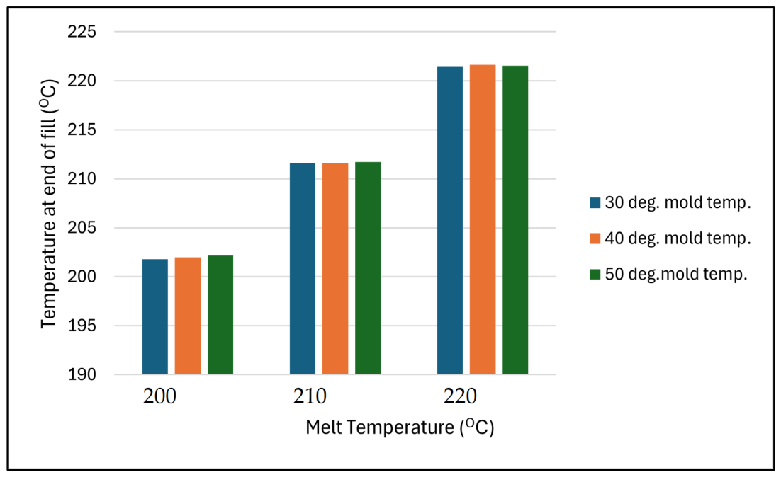
To assess the extent of material degradation at the end of the mould filling process, a simulation was performed to evaluate the temperature at this critical stage. Additionally, as highlighted in the work of Karagöz and Tuna [58]. Various mould and melt temperatures were examined, as illustrated in Figure 6.
A clear trend was observed: as the melt and mould temperatures increased, so did the temperature at the end of the simulation. However, this rise was not significant across all three scenarios examined, suggesting that other influencing factors may be involved. Additionally, fill time was found to increase with higher temperatures, which can be attributed to the relatively low injection pressure used during mould filling. Importantly, the simulation results showed that temperatures remained below 230 °C in all cases, indicating that fibre degradation is unlikely under these conditions. Another notable finding was the inverse relationship between temperature and pressure at the end of fill; higher melt temperatures resulted in lower pressures. This suggests that elevated melt temperatures may facilitate flow, potentially improving processing efficiency and maintaining material integrity during production.

4.4. Produced Sample

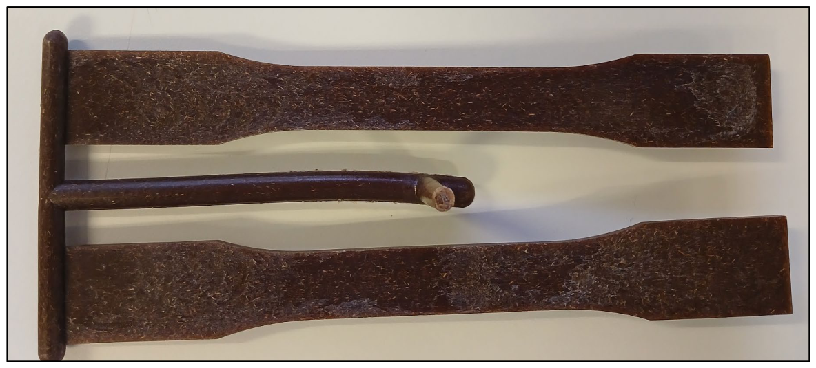
Figure 7 shows the sample produced using the plastic flow simulation results, indicating a well-dispersed fibre phase in the polymer matrix in the direction of flow. As the polymer melt fills the mould cavity, hydrodynamic forces and shear gradients act on the discontinuous fibres, causing them to reorient along or orthogonal to the primary flow direction. In addition, no visible defects such as sink marks or warpage were observed on the specimen. Moreover, the absence of carbonisation suggests that thermal exposure during processing did not cause fibre degradation. These findings are consistent with those reported by Saha et al. [59] who highlighted the importance of understanding the mould-filling behaviour of fibre-reinforced polymer composites to achieve the desired material and mechanical properties.

5. Conclusions

The use of proper design in developing 3D moulds and conducting plastic injection simulations can significantly reduce the number of polymer composite specimens required for experimental testing. This approach minimizes both trial-and-error iterations and the likelihood of producing defective specimens. SolidWorks mould design tools can identify design issues such as insufficient draft angles early in the design phase, ensuring easy de-moulding and improved manufacturability. Furthermore, the software facilitates the generation of part geometry for plastic injection simulation, as well as core and cavity configurations needed to produce machine code for manufacturing the physical product. Simulation results indicated that, for a 4 mm thick plantain fibre reinforced composite specimen, an injection pressure of 75 MPa was optimal. As the pressure resulted in complete cavity filling. The end of fill temperature analysis confirmed that fibre degradation is unlikely under the tested simulation conditions. Given the current increase in energy costs, employing lower melt and mould temperatures is desirable, particularly since the three temperature settings used in this study yielded comparable results. However, this study did not include the evaluation of potential defects such as sink marks, warpage, and shrinkage, which are also important in injection mould products. A more comprehensive analysis, including defect identification and production parameter optimization, could further improve the reliability and quality of the injection-moulded components.

Author Contributions

Conceptualization, J.A. and W.S.E.; methodology, J.A.; software, J.A.; formal analysis, J.A.; investigation, J.A., W.S.E. and P.Y.T.; writing—resources, P.Y.T.; writing—original draft preparation, J.A., writing—review and editing, supervision, J.A., W.S.E. and P.Y.T. All authors have read and agreed to the published version of the manuscript.

Funding

The authors acknowledge the conference sponsorship by Durban University of Technology, South Africa.

Institutional Review Board Statement

Ethical review approval was waived for this study because it involves no more than minimal risk to participants, does not involve any vulnerable populations or sensitive topics, and it meets the criteria for exemption under category one.

Informed Consent Statement

Not applicable.

Data Availability Statement

Data will be made available on reasonable request to the corresponding author.

Acknowledgments

The authors acknowledge the general support, provision of facilities, and software for this study by the Durban University of Technology, South Africa.

Conflicts of Interest

The authors declare no conflicts of interest.

Abbreviations

The following abbreviations are used in this manuscript:
3DThree-Dimension
CAEComputer-Aided Engineering
HDPEHigh-Density Polyethylene
CADComputer-Aided Design

References

  1. Rajak, D.K.; Pagar, D.D.; Menezes, P.L.; Linul, E. Fiber-Reinforced Polymer Composites: Manufacturing, Properties, and Applications. Polymers 2019, 11, 1667. [Google Scholar] [CrossRef]
  2. Vimalanathan, P.; Suresh, G.; Rajesh, M.; Manikandan, R.; Kanna, S.K.R.; Santhanam, V. A Study on Mechanical and Morphological Analysis of Banana/Sisal Fiber Reinforced IPN Composites. Fibers Polym. 2021, 22, 2261–2268. [Google Scholar] [CrossRef]
  3. Mihut, D.M.; Afshar, A.; Kennedy, D. Mechanical Evaluation of 3D Printed Polymers—A New Lab Design; American Society for Engineering Education: Washington, DC, USA, 2020; Available online: https://sites.asee.org/se/wp-content/uploads/sites/56/2021/01/2020ASEESE91.pdf (accessed on 26 August 2025).
  4. Fu, H.; Xu, H.; Liu, Y.; Yang, Z.; Kormakov, S.; Wu, D.; Sun, J. Overview of injection molding technology for processing polymers and their composites. ES Mater. Manuf. 2020, 8, 3–23. [Google Scholar] [CrossRef]
  5. Shrivastava, P.; Yaduwanshi, D.K.; Mishra, V.; Ghosh, A.; Ahmad, A.H.; Birla, S.K.; Sahoo, N. A Comprehensive Review of Composite Materials: Current and Future Prospects in Aerospace Applications. Polym. Compos. 2025, 1–36. [Google Scholar] [CrossRef]
  6. Amran, M.; Faizal, K.; Salleh, M.; Sulaiman, M.; Mohamad, E. Design consideration for design a flat and ring plastics part using Solidworks software. IOP Conf. Ser. Mater. Sci. Eng. 2015, 100, 012050. [Google Scholar]
  7. Advani, S.G. 2.2 Role of Process Models in Composites Manufacturing. In Comprehensive Composite Materials II; Beaumont, P.W.R., Zweben, C.H., Eds.; Elsevier: Oxford, UK, 2018; pp. 24–41. [Google Scholar]
  8. Ebnesajjad, S. 7—Injection Molding. In Melt Processible Fluoroplastics; Ebnesajjad, S., Ed.; William Andrew Publishing: Norwich, NY, USA, 2003; pp. 151–193. [Google Scholar]
  9. Rabbi, M.S.; Islam, T.; Islam, G.M.S. Injection-molded natural fiber-reinforced polymer composites—A review. Int. J. Mech. Mater. Eng. 2021, 16, 15. [Google Scholar] [CrossRef]
  10. Coates, P.D.; Whiteside, B.R.; Martyn, M.T.; Spares, R.; Gough, T. Micromoulding—Precision processing for controlled products. In 4M 2006—Second International Conference on Multi-Material Micro Manufacture; Menz, W., Dimov, S., Fillon, B., Eds.; Elsevier: Oxford, UK, 2006; pp. 13–15. [Google Scholar]
  11. Kovacs, J.G.; Bercsey, T. Influence of mold properties on the quality of molded parts. Period. Polytech. SER. MECH. ENG. 2005, 49, 115–122. [Google Scholar]
  12. Wang, J.; Mao, Q.; Jiang, N.; Chen, J. Effects of Injection Molding Parameters on Properties of Insert-Injection Molded Polypropylene Single-Polymer Composites. Polymers 2022, 14, 23. [Google Scholar] [CrossRef]
  13. Vasiliev, V.V.; Morozov, E.V. Mechanics and Analysis of Composite Materials; Elsevier: Amsterdam, The Netherlands, 2001. [Google Scholar]
  14. Binqi, R.; Hongwei, Z.; Huabin, O.; Yanjian, W.; Yuanhui, Z.; Jingyang, W. Study on the clamping force measurement and partial load regulation technology of injection molding machine. CIRP J. Manuf. Sci. Technol. 2017, 19, 19–24. [Google Scholar] [CrossRef]
  15. Xavier, S.F.; Tyagi, D.; Misra, A. Influence of Injection-Molding Parameters on the Morphology and Mechanical Properties of Glass Fiber-Reinforced Polypropylene Composites. Polym. Compos. 1982, 3, 90. [Google Scholar]
  16. Bhaskar, D.; Suresh, G.; Ganesamoorthy, R.; Srinivasan, T.; Dharmendra, B.V.; Meenakshi, C.M.; Selva Ganapathy, K. Behaviour of Fibre Length in Banana Fibre Reinforced Thermoplastic Composites Under High Velocity Impact Performance. In Recent Advances in Materials and Modern Manufacturing; Palani, I.A., Sathiya, P., Palanisamy, D., Eds.; Springer Nature: Singapore, 2022; pp. 1029–1037. [Google Scholar]
  17. Chen, S.-C.; Peng, H.-S.; Huang, L.-T.; Chung, M.-S. Investigations of the Tensile Properties on Polycarbonate Thin-Wall Injection Molded Parts. J. Reinf. Plast. Compos. 2003, 22, 479–494. [Google Scholar] [CrossRef]
  18. Srinivasan, T.; Suresh, G.; Ramu, P.; Ram, V.G.; Giresh, M.; Arjun, K. Effect of water absorption of the mechanical behavior of banana fiber reinforced IPN natural composites. Mater. Today Proc. 2021, 45, 1334–1337. [Google Scholar] [CrossRef]
  19. Tesfaw, S.; Bogale, T.M.; Fatoba, O. Evaluation of tensile and flexural strength properties of virgin and recycled high-density polyethylene (HDPE) for pipe fitting application. Mater. Today Proc. 2022, 62, 3103–3113. [Google Scholar] [CrossRef]
  20. ASTM D638; Tensile Properties of Plastics. ASTM: West Conshohocken, USA, 2003.
  21. Krishnappa, M.; Nagaraja, S.; Munegowda, N.; Ammarullah, M.I. Design and Analysis of Injection Molds for Plastic Components for Biomedical Applications. Eng. Rep. 2025, 7, e70070. [Google Scholar] [CrossRef]
  22. Kurt, M.; Kamber, O.S.; Kaynak, Y.; Atakok, G.; Girit, O. Experimental investigation of plastic injection molding: Assessment of the effects of cavity pressure and mold temperature on the quality of the final products. Mater. Des. 2009, 30, 3217–3224. [Google Scholar] [CrossRef]
  23. Min, B.H. A study on quality monitoring of injection-molded parts. J. Mater. Process. Technol. 2003, 136, 1–6. [Google Scholar] [CrossRef]
  24. Bennett, L. The Importance of Uniform Wall Thickness in Injection Molding [Guide]. Available online: https://www.rapiddirect.com/blog/injection-molding-wall-thickness/ (accessed on 12 December 2022).
  25. Park, H.-P.; Cha, B.-S.; Park, S.-B.; Choi, J.-H.; Kim, D.-H.; Rhee, B.-O.; Lee, K.-H. A Study on the Void Formation in Residual Wall Thickness of Fluid-Assisted Injection Molding Parts. Adv. Mater. Sci. Eng. 2014, 2014, 238251. [Google Scholar] [CrossRef]
  26. Melito, S. Wall Thickness Recommendations for Injection Molding. Available online: https://www.fictiv.com/articles/wall-thickness-recommendations-for-injection-molding (accessed on 1 May 2023).
  27. Stratasys. Three Mistakes to Avoid when Designing for Injection Molding. Available online: https://www.stratasys.com/en/stratasysdirect/resources/articles/injection-molding-design-mistakes/ (accessed on 8 December 2022).
  28. Cannanda, R. 5 Design Rules for: Problem Free Injection Molded Plastic Parts. Available online: https://dfmpro.com/category/design-for-manufacturing/page/5/ (accessed on 12 August 2022).
  29. Patcharaphun, S.; Jariyatammanukul, P. The effect of thickness on the weld-line strength of injection-molded thermoplastic composites. Polym.-Plast. Technol. Eng. 2010, 49, 1305–1309. [Google Scholar] [CrossRef]
  30. MacLean-Blevins, M.T. 6—Preliminary detailed design. In Designing Successful Products with Plastics; MacLean-Blevins, M.T., Ed.; William Andrew Publishing: Norwich, NY, USA, 2018; pp. 127–195. [Google Scholar]
  31. Pouzada, A.S.; Ferreira, E.; Pontes, A. Friction properties of moulding thermoplastics. Polym. Test. 2006, 25, 1017–1023. [Google Scholar] [CrossRef]
  32. Throne, J. 16—Thermoforming. In Applied Plastics Engineering Handbook, 2nd ed.; Kutz, M., Ed.; William Andrew Publishing: Norwich, NY, USA, 2017; pp. 345–375. [Google Scholar]
  33. MacLean-Blevins, M.T. 7—Final detailed design. In Designing Successful Products with Plastics; MacLean-Blevins, M.T., Ed.; William Andrew Publishing: Norwich, NY, USA, 2018; pp. 197–223. [Google Scholar]
  34. Vasco, J.; Capela, C.; Bartolo, P.; Granja, D. Material Selection For High Performance Moulds. 2007. Available online: https://www.researchgate.net/profile/Joel-Vasco/publication/321655356_MATERIAL_SELECTION_FOR_HIGH_PERFORMANCE_MOULDS/links/5a29e6250f7e9b63e5353a92/MATERIAL-SELECTION-FOR-HIGH-PERFORMANCE-MOULDS.pdf (accessed on 15 December 2022).
  35. Ebhota, W.S.; Inambao, F.L. Smart Design and Development of a Small Hydropower System and Exploitation of Locally Sourced Material for Pelton Turbine Bucket Production. Iran. J. Sci. Technol. Trans. Mech. Eng. 2017, 43, 291–314. [Google Scholar] [CrossRef]
  36. Rahim, M.A.A.A.; Musa, N.; Ramesh, S.; Lim, M.K. A systematic review on material selection methods. Proc. Inst. Mech. Eng. Part L J. Mater. Des. Appl. 2020, 1, 28. [Google Scholar] [CrossRef]
  37. Arora, A.; Pathak, A.; Juneja, A.; Shakkarwal, P.; Kumar, R. Design and analysis of multi cavity injection mould using solidworks. Mater. Today Proc. 2022, 56, 3648–3650. [Google Scholar] [CrossRef]
  38. Huang, G.; Wu, X.; Li, X.; Li, J. Optimized Design of Cavity Layout and Feed System of Multi-cavity Injection Mould. In Proceedings of the 2009 International Joint Conference on Artificial Intelligence, Hainan, China, 25–26 April 2009; IEEE: New York, NY, USA, 2009; pp. 651–654. [Google Scholar] [CrossRef]
  39. Rees, H. Injection Mold Design; Hanser Publishers: Munich, Germany, 2001. [Google Scholar]
  40. Chang, R.-Y.; Huang, C.-T. CAE for Advanced Injection Molding Technologies. In Advanced Injection Molding Technologies; Chen, S.-C., Turng, L.-S., Eds.; Hanser: Munich, Germany, 2019. [Google Scholar]
  41. Solanki, B.S.; Singh, H.; Sheorey, T. Modeling and analysis of cavity modification effect on quality of injection molded polymer gear. Int. J. Interact. Des. Manuf. (IJIDeM) 2022, 16, 1615–1632. [Google Scholar] [CrossRef]
  42. Travaglini, V.; Rozema, H. Chapter 6: Mold Making and Plasticization Advances in Stack Molding Technology. In Specialized Molding Techniques: Application, Design, Materials and Processing; William Andrew Publishing: Norwich, NY, USA, 2002; p. 259. [Google Scholar]
  43. Lin, C.-C.; Wu, T.-C.; Chen, Y.-S.; Yang, B.-Y. A Semi-Analytical Method for Designing a Runner System of a Multi-Cavity Mold for Injection Molding. Polymer 2022, 14, 5442. [Google Scholar] [CrossRef]
  44. Jones, P. The Mould Design Guide; Rapra Technology Ltd.: Shawbury, UK, 2008. [Google Scholar]
  45. Yavari, R.; Khorsand, H. Numerical and experimental study of injection step, separation, and imbalance filling in low pressure injection molding of ceramic components. J. Eur. Ceram. Soc. 2021, 41, 6915–6924. [Google Scholar] [CrossRef]
  46. Cao, S.; Si, G. Design of an Automobile Injection Mould Based on Automation Technology. Mob. Inf. Syst. 2022, 2022, 8224364. [Google Scholar] [CrossRef]
  47. Moayyedian, M.; Abhary, K.; Marian, R. Improved Gate System for Scrap Reduction in Injection Molding Processes. Procedia Manuf. 2015, 2, 246–250. [Google Scholar] [CrossRef]
  48. Lerma Valero, J.R. Chapter 24—Typical Problems in Plastics Injection. In Plastics Injection Molding; Lerma Valero, J.R., Ed.; Hanser: Munich, Germany, 2020; pp. 315–327. [Google Scholar]
  49. Gan, I. (Ed.) A Design Guide Part and Mold Design Engineering Polymers; Bayer Engineering Polymers Propertie: Leverkusen, Germany, 2000; Available online: https://kompozit.org.tr/wp-content/uploads/2021/11/A_Design_Guide_Part_and_Mold_Design_Engi.pdf (accessed on 5 February 2023).
  50. Seo, T.-I.; Song, B.-U.; Lee, J.-W. Design and fabrication of multi-cavity injection mold using hot runners and direct edge gates. Proc. Inst. Mech. Eng. Part C J. Mech. Eng. Sci. 2014, 228, 2790–2798. [Google Scholar] [CrossRef]
  51. Papathanasiou, T.D.; Kuehnert, I.; Polychronopoulos, N.D. 5—Flow-induced alignment in injection molding of fiber-reinforced polymer composites. In Flow-Induced Alignment in Composite Materials, 2nd ed.; Papathanasiou, T.D., Bénard, A., Eds.; Woodhead Publishing: Cambridge, UK, 2022; pp. 123–185. [Google Scholar]
  52. Kazmer, D.O. Injection Mold Design Engineering; Hanser: Munich, Germany, 2016. [Google Scholar]
  53. Abdulrahman, J.; Ebhota, W.S.; Tabakov, P.Y. Optimisation of plastic injection moulding parameters for biopolymer composite using Taguchi L9 method and mould flow analysis. Results Mater. 2025, 26, 100705. [Google Scholar] [CrossRef]
  54. System, D. Solid Work Plastic. Available online: https://www.solidworks.com/product/solidworks-plastics (accessed on 5 February 2023).
  55. Nishihara, T.; Nakamura, Y.; Maeda, Y. Shrinkage Cavities in Conical Mold Castings of Aluminum Alloy. Int. J. Met. 2023, 17, 2431–2438. [Google Scholar] [CrossRef]
  56. Manohar, K.; Adeyanju, A.A. A comparison of banana fiber thermal insulation with conventional building thermal insulation. Br. J. Appl. Sci. Technol. 2016, 17, 1–9. [Google Scholar] [CrossRef]
  57. Deepa, B.; Abraham, E.; Cherian, B.M.; Bismarck, A.; Blaker, J.J.; Pothan, L.A.; Leao, A.L.; de Souza, S.F.; Kottaisamy, M. Structure, morphology and thermal characteristics of banana nano fibers obtained by steam explosion. Bioresour. Technol. 2011, 102, 1988–1997. [Google Scholar] [CrossRef]
  58. Karagöz, İ.; Tuna, Ö. Effect of melt temperature on product properties of injection-molded high-density polyethylene. Polym. Bull. 2021, 78, 6073–6091. [Google Scholar] [CrossRef]
  59. Saha, S.; Kumar, V.; Prabhune, B.; Limaye, M.; Rodriguez, B.; Garg, N.; Kim, S.; Hassen, A.A.; Tsiamis, N.; Meraki, Y.; et al. Development of fiber orientation in injection molding: Comparison of glass fiber, carbon fiber and their hybrid composites. Compos. Commun. 2025, 58, 102496. [Google Scholar] [CrossRef]
Figure 1. Simulation specimen: (a) 2D dimensions, (b) 3D model.
Materproc 31 00033 g001
Figure 2. 3D mould core and cavity.
Materproc 31 00033 g002
Figure 3. Sample production: (a) compounding, (b) pelletizing, and (c) injection moulding.
Materproc 31 00033 g003
Figure 4. Draft analysis: (a) require draft angle, (b) adequate draft angle.
Materproc 31 00033 g004
Figure 5. Filling analysis: (a) short shot, (b) complete fill.
Materproc 31 00033 g005
Figure 6. Temperature comparison at the end of fill.
Materproc 31 00033 g006
Figure 7. Injection mould sample.
Materproc 31 00033 g007
Table 1. Simulation material properties.
HDPEBanana Fibre
Density (Kg/m3)934750
Thermal Conductivity (W/m·K)0.33 *0.04 [56]
Melt Temperature (°C)190-
Elastic Modulus (MPa)500 *
Poisson’s Ratio0.46 *0.25
Thermal Coefficient of Expansion (1/K)120 × 10−610−7 [57]
Specific Heat (N·m/Kg·K)260 *-
Weight Ratio (%)7030
* D. Systems. High-density polyethylene (HDPE) material data in SOLIDWORKS Plastics Material Library, Version 2024.
Disclaimer/Publisher’s Note: The statements, opinions and data contained in all publications are solely those of the individual author(s) and contributor(s) and not of MDPI and/or the editor(s). MDPI and/or the editor(s) disclaim responsibility for any injury to people or property resulting from any ideas, methods, instructions or products referred to in the content.