


Abstract
An experimental study of closed hollow sections subjected to torsional loading was conducted. The aim was to examine the torsional behavior of thick-walled 6061-T6 aluminum alloy tubes. The test plan included three sets of circular and rectangular tubes, each with six specimens for a total of 36 torsion tests. Experimental data were used to estimate torsional stiffness, and both first-yield and full plastic-yield strengths. Experimental estimates were compared with theoretical predictions, as well as with values computed using the Aluminum Association’s Specification for Aluminum Structures (SAS) design rules. The SAS provisions were found to be overly conservative for thick-walled circular tubes, while fairly close agreement between SAS’s shear modulus (C) and the torsional plastic section modulus (ZT) resulted in more accurate results for thick-walled rectangular tubes.
1. Introduction
Aluminum hollow structural members are widely used in engineering applications where low weight, corrosion resistance, and structural efficiency are important [1]. In many such applications, the members are used to resist twisting action, making accurate prediction of torsional stiffness and strength essential for safe and economical design [2]. For closed thin-walled sections, torsional strength limit states are well defined and idealized; however, the behavior of thick-walled hollow members, particularly in aluminum, is less thoroughly documented. In thick-walled hollow sections, the shear stress distribution across the wall thickness is inherently non-uniform, unlike the idealized constant stress typically assumed in thin-walled Bredt’s theory [3]. Under increasing torsional load, yielding initiates at the outer fibers of the thickness and gradually propagates inward toward the inner surface until a fully plastic state is reached [4]. This radial stress gradient and the subsequent progression of plastic deformation are highly dependent on the specific cross-sectional geometry [5]. Consequently, relying on initial-yield criteria rather than capturing this full-plastic progression can lead to an underestimation of a member’s true ultimate strength. As a result, questions remain regarding the suitability of current design provisions for best capturing the actual torsional resistance of certain shapes.
There is also somewhat limited published research on the torsional testing of large-scale thick-walled tubular members [6]. The present study investigates the torsional behavior of thick-walled hollow 6061-T6 aluminum members with rectangular and circular cross-sections through an experimental program including 36 specimens. The measured torque-rotation responses are used to evaluate torsional stiffness, ductility, and strength, including both initial-yield and full-yield capacities, and to make comparisons with theoretical predictions and the torsional design provisions in the Aluminum Association’s Specification for Aluminum Structures (SAS) [7], which is found in Part 1 of the Aluminum Design Manual (ADM) [8]. Through the integration of this experimental data and subsequent finite element studies, this work aims to propose revised design equations that better reflect the full-yield behavior of thick-walled aluminum tubes. Such revisions would align the industry more closely with a strength limit states design philosophy, ensuring that aluminum structural components are both safe and economically optimized [9].
2. Materials and Methods
The study focused on characterizing the torsional behavior of thick-walled aluminum alloy tubes. Tensile tests were first conducted to determine experimental values of the elastic (Young’s) modulus, yield strength, and ultimate strength of the material to be torsionally tested, and were subsequently used in the analysis of the torsion data.
2.1. Test Specimens
All experimentation was conducted on 6061-T6 aluminum alloy specimens. The material was supplied by the manufacturer as constant-thickness circular and square tube stock, in lengths of 1.83 m (6 ft). Two-thirds of each piece of tube stock, or 1219 mm (4 ft), was used for torsion testing, and the remaining one-third, or 610 mm (2 ft), was used for tensile testing.
2.1.1. Tensile Specimens
All tensile specimens were manufactured in accordance with ASTM’s Standard Test Methods for Tension of Metallic Materials [10]. For the hollow square tubes, dogbone-shaped tensile coupons with rectangular cross-sections were cut from each side of the specimen, producing a total of four coupons per piece of stock. Due to size, geometry, and machining limitations, only two curved tensile coupons were cut from each of the hollow circular stock pieces.
2.1.2. Torsion Specimens
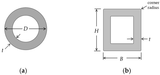
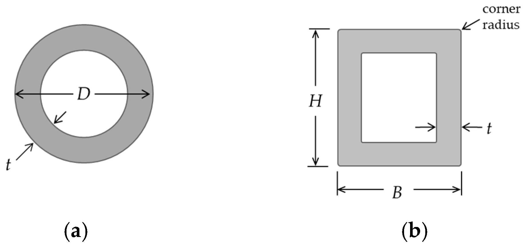
Thirty-six torsion tests were performed, including six different test series with six specimens in each. Three series examined thick-walled circular hollow sections (CHS) with outer diameters of D = 38.1 mm (1.5 in.), and with constant wall thickness t (Figure 1a). The wall thicknesses examined were 6.35, 3.18, and 1.59 mm. The three rectangular test series included three different thick-walled rectangular hollow sections (RHS), all with base-to-height aspect ratios of 1.0 (i.e., square geometry) and outer base dimension B = H = 38.1 mm (1.5 in.), as can be seen in Figure 1b. The same wall thicknesses were studied for the square and the circular tubes (Table 1). Four specimens per series had a length of 0. 610 m (2 ft) and two had a length of 1.22 m (4 ft).
Figure 1.
Cross-sections of torsion specimens studied. (a) Circular hollow section (CHS) with outer diameter D and wall thickness t. (b) Rectangular hollow section (RHS) with outer base B equal to outer depth H, and wall thickness t.
Table 1.
Description of the six torsion-test series.
The test specimen labels indicate cross-section shape and dimensions. The first part of the label specifies the shape of the specimen cross-section, with “CHS” indicating a circular hollow shape and “RHS” indicating a rectangular hollow shape. The second part of the label is associated with the cross-sectional dimensions. For the circular specimens, “D38” indicates the outer diameter is 38.1 mm, and for the rectangular specimens, “BH38” refers to both the outer base and outer height equal to 38.1 mm. The final portion of the label provides the constant wall thickness t in mm.
2.2. Test Procedures
2.2.1. Tensile Testing
Tension testing was conducted at 5 mm/min in accordance with ASTM-E8 [10], on an Instron (Norwood, MA, USA) 5584 Universal Testing Machine with a load cell capacity of 200 kN. An extensometer attached to the specimen was used to record displacement data. Engineering stress and strain were computed from the force-displacement data and used to estimate the values of Young’s modulus (E), the 0.2% offset yield stress (Fy), and the tangent modulus or slope at the yield point (E0.2) of each specimen. The axial stiffness reduction ratio, , was then computed as the ratio of the two moduli (Equation (1)) and used to characterize the stiffness degradation at the point where an axial tension member achieves full-plastic yielding [3]. Ratio was subsequently used, together with a torsional stiffness reduction ratio, to estimate the plastic torque Tp corresponding to full-plastic yield of a torsion specimen of the same alloy [11].
A summary of the tensile properties of the 6061-T6 stock material, in comparison with the SAS specified values, is displayed in Table 2. The SAS values for yield strength () and stiffness () are 240 MPa and 70 GPa, respectively.
Table 2.
Summary of tensile test results. Median values of measured material properties of tensile coupons (with superscript tt) compared with specified values in SAS [7].
2.2.2. Torsion Testing
The experimental program used a Tinius-Olsen (Horsham, PA, USA) torsion machine with a moment capacity of 6800 N·m (60,000 lb-in) to test the 6061-T6 thick-walled tubes described in Table 1. The machine allows large twist angles in a single continuous test without restraining axial deformation. CHS specimens were machined from stock material in accordance with ISO Metallic Materials—Torsion Test at Room Temperature [12], using a parallel length equal to the sum of the gauge length and twice the outside diameter D. Although no specific standard exists for RHS specimens subjected to pure torsion, those specimens were machined to the same length as the CHS specimens for consistency. Each test series included four specimens with L = 610 mm (24 in.) and two longer specimens (L = 1219 mm = 48 in.) in order to evaluate possible length effects, with the remaining material reserved for tensile testing as previously described in Section 2.1. Each hollow end of the torsion specimens was fitted with an aluminum plug to prevent crushing of the 76.2 mm (3 in.) length engaged by the grips.
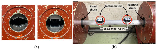
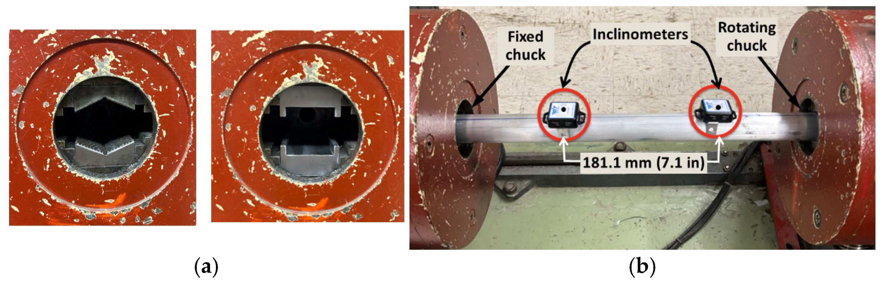
Custom grips were used to secure each shape (Figure 2a), and six specimens were tested per series at a rate of 0.524 rad/min. Torque and angular displacement were measured using WitMotion (Shenzhen, China) Bluetooth 2.0 wireless inclinometers with a static angle accuracy of 872.7 μrad (0.05°). Two inclinometers were mounted on each specimen at a constant separation distance, as shown in Figure 2b, and rotations at both locations were recorded every 0.1 s. Angular deformation was computed as the difference between the two recorded rotations. A third sensor was used in conjunction with the load dial to record the applied torque simultaneously, resulting in torque and angular deformation data for each specimen tested.
Figure 2.
Torsion testing apparatus. (a) Custom grips for circular and square specimens. (b) Front view of torsion test setup, with two inclinometers mounted on a hollow circular specimen.
2.3. Theoretical Framework and Data Analysis
The resulting torsion data, including torque T and the corresponding angular deformation , were obtained for each thick-walled tubular specimen during testing. The data were analyzed to estimate the torsional stiffness and the torques associated with initial-yielding and full-plastic yielding of each specimen. Experimental results were subsequently compared with the theoretical predictions and values.
2.3.1. Circular Tubes
During torsion of a hollow circular tube, the shear stress varies linearly with radial position ρ, first reaching a maximum at the outer radius [3]. As the applied torque T increases to the yield torque , yielding initiates simultaneously along the outer surface, where the shear stress is equal to . For , yielding propagates inward toward smaller radii (ρ < ). Assuming elastic–perfectly plastic material behavior, the yielded region sustains a constant shear stress . At full plasticity, the entire cross-section () is at , and the corresponding torque is defined as the fully plastic torque .
For circular hollow shapes (CHS) with wall thickness t, outer radius , and inner radius , the shear stress at which first-yield occurs is defined as:
where the torsional constant JT is equal to the polar area moment of inertia J of the section, and Ty represents the applied torque at the onset of yielding. Ty can be thus written as
where is the torsional elastic section modulus. Per Equations (2) and (3), for hollow circular cross-sections. Incorporating the von Mises yield criterion [3] that defines the shear yield stress , where is the tensile yield stress of the material, the first-yield criterion can be presented as
As the torque continues to increase, yielding progresses inward from the outer surface of the tube until the cross-section fully yields when the torque reaches the plastic value Tp. Assuming that no strain hardening occurs at the surface of the rod, the fully plastic torque is thus defined as
where ZT is the torsional plastic section modulus.
2.3.2. Rectangular Tubes
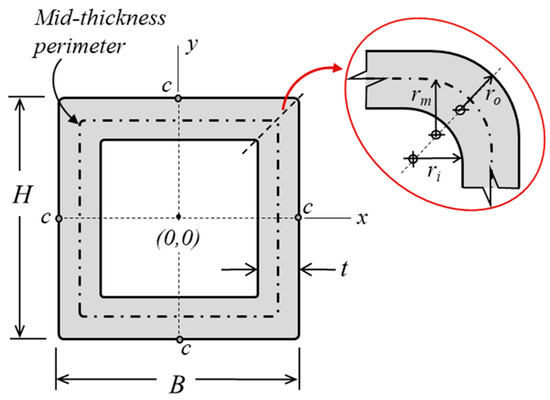
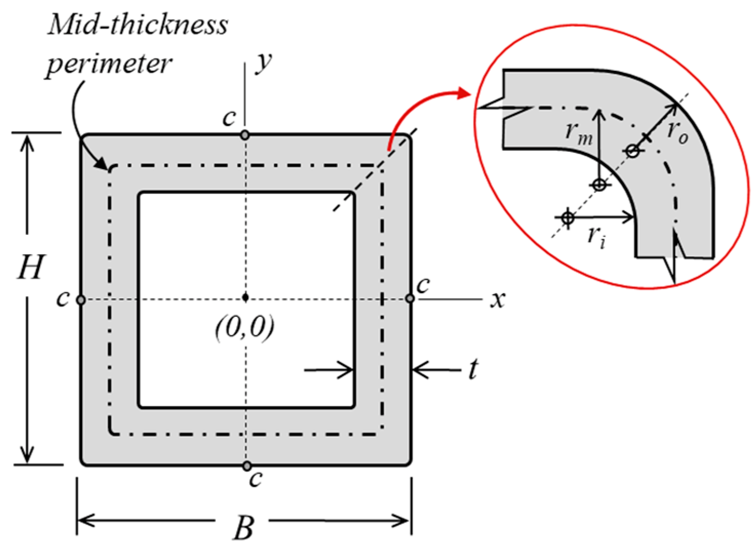
For rectangular sections under torsion, shear stress is not proportional to radial distance due to warping effects [13]. As a result, the shear stress distribution is nonlinear. The maximum shear stress can be determined using Prandtl’s membrane analogy [14], which relates the torsional shear stresses to the shape of an inflated membrane over the cross-section. For hollow rectangles (B ≠ H), occurs at the midpoint of the longer sides on the outer surface. For square sections (B = H), occurs at the midpoint of each side (e.g., point c in Figure 3). Neglecting stress concentrations, the shear stress theoretically reduces to zero at the corner points.
Figure 3.
Thick-walled hollow rectangular tube with rounded corners. The corner geometry, generally defined by inner and outer radii ( and , respectively) with distinct curvature centers, is shown for the constant-radius case with ==.
For thick-walled RHS, several theories also account for the variation in shear stress through the wall thickness [15,16,17]. Marshall [17], for example, estimated the shear stress variation through the thickness to be nearly linear in thick-walled RHS, and proposed simplified expressions as practical approximations of his detailed analysis [6]. These expressions provide an estimate of the torque Ty associated with the first yield of thick-walled RHS defined by width B, depth H, wall thickness t, internal corner radius ri, mid-thickness corner radius rm, and outer corner radius ro (Figure 3).
The torsional constant for a thick-walled rectangular section, , as derived by Marshall [17], is defined as
where and are the mid-thickness perimeter of the section (dashed line in Figure 3) and the area enclosed by it, respectively. The resulting torque associated with the initial yield of a thick-walled RHS is thus
where is the torsional elastic section modulus. For the special case of a hollow square with non-rounded corners, B = H and = = = 0, and the first-yield torque simplifies to
The torque then continues to increase, yielding progresses inward from the outer surface through the thickness of the RHS. The torque associated with the full-plastic yield of a thick-walled hollow rectangular section [18] is determined to be
In the special case of a square, with B = H, this expression becomes
and in the limit of corner radius === 0, the expression simplifies to
3. Results
In this section, the results of the experimental testing are analyzed and compared with the theoretical predictions.
3.1. Torsional Stiffness
For each specimen, the slope of the linear elastic portion of the experimental response was determined by least-squares regression and taken as the torsional stiffness, k. The median of the six stiffness values in each test series is defined herein as the experimental torsional stiffness, . This value was compared with two calculated values of , denoted and , where the superscript identifies the elastic modulus used in the calculation, i.e., and , respectively. In both cases, the calculations used the appropriate theoretical expression for the torsion constant (), the experimental gauge length L = 181.5 mm, and the shear modulus determined from the theoretical relationship [3]
with Poisson’s ratio ν = 0.33. For , the elastic modulus was set to = 70 GPa, and for , the modulus E was set to the median of the least-squares values determined from the relevant tension tests,.
Table 3 presents comparisons of the experimental torsional stiffnesses and the computed values. The table reveals that the median experimental values were within 0.92 and 1.04 times the computed values for all test series, with overall mean and median comparisons (for all six test series) of 0.99 and 1.01, respectively, thereby supporting the validity of the test apparatus and experimental procedures.
Table 3.
Comparison of computed values for torsional stiffness, k = GJ/L, with least-squares slope of experimental torsion data. Median values are presented for each test series.
3.2. Torsional Strengths
The experimental torque–angular displacement data, together with the previously described stiffness degradation β0.2 method, were first used to determine the experimentally measured full-plastic yield torque, . A shear yield stress of was then adopted, where 0.577 corresponds to the von Mises yield criterion [3], and is the median 0.2% offset tensile yield strength obtained from the coupon tests. Using this shear yield stress, the theoretical full-plastic yield torque, , was computed using Equation (4) for CHS specimens and Equation (7) for RHS specimens.
These experimental and theoretical values were then compared with the nominal torque, , currently prescribed by SAS [7], as well as with the authors’ proposed nominal torque, , which is intended for consideration in a forthcoming edition of SAS. For both nominal torque calculations, the SAS-prescribed shear strength, , was used. In this expression, 0.6 is the defined estimate of the von Mises criterion, and is the SAS-specified minimum tensile yield strength, which is 240 MPa for the case of 6061-T6 aluminum. The torsional plastic section modulus, , used in the proposed expression, was computed using Equation (4) for CHS specimens and Equation (7) for RHS specimens.
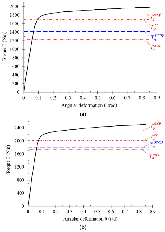
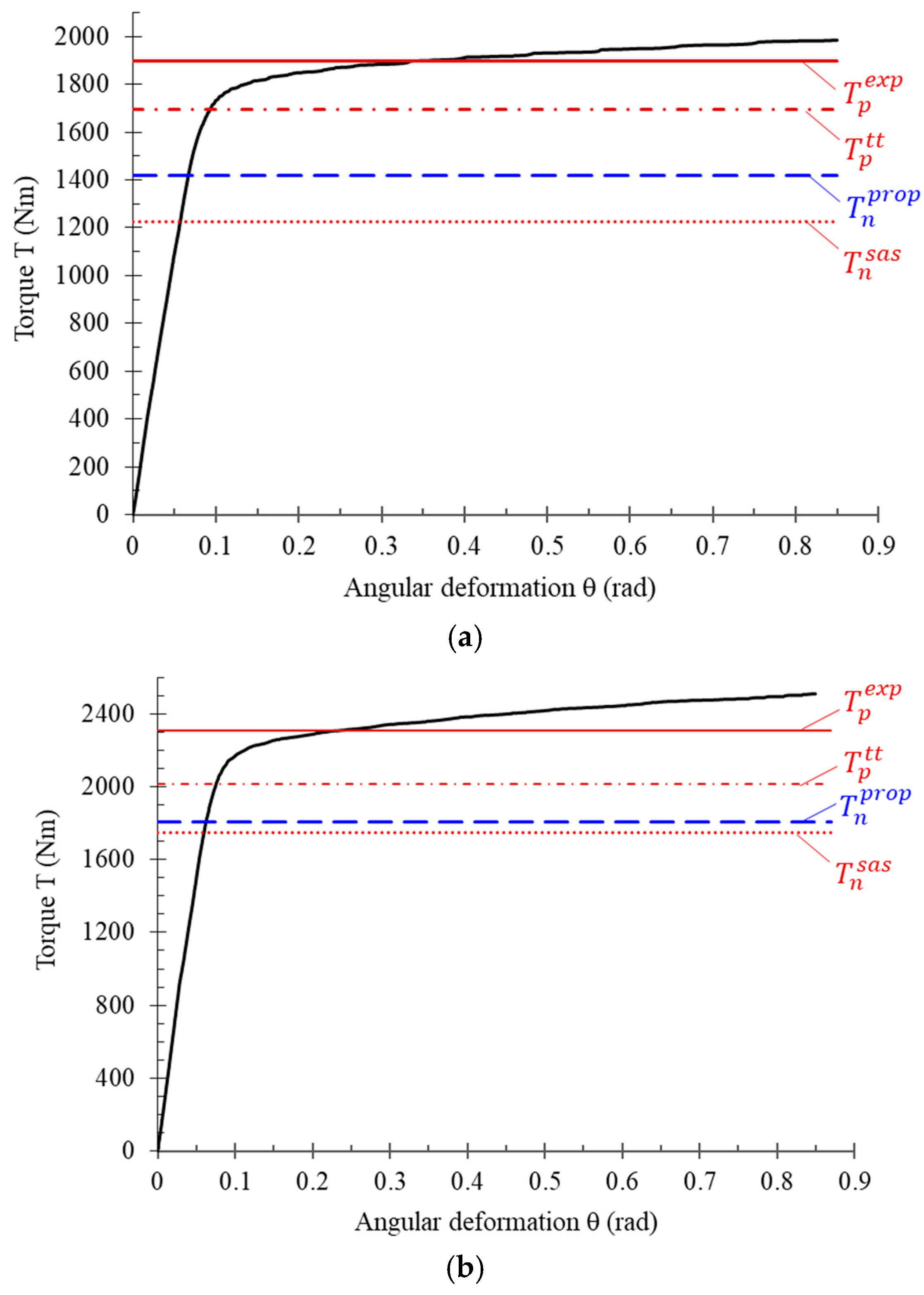
A graphical comparison of the results is presented in Figure 4, which shows representative - curves for each cross-sectional geometry with a wall thickness of 6.35 mm (0.25 in). Three key observations can be made. First, the experimental results demonstrate substantial ductility, with angular (twist) deformations extending well beyond 0.9 rad. Second, the measured torsional strengths significantly exceed the current SAS nominal strengths. Third, the proposed nominal torque expression recovers a portion of the significant conservatism inherent in the current SAS provisions, while remaining below the experimentally observed strengths.
Figure 4.
Representative plots of torsion test results for tubes with wall thickness t = 0.635 mm (0.25 inch), including (a) CHS-D38-t6.35 and (b) RHS-BH38-t6.35. Experimentally determined full-plastic yield torques, and are shown with the current nominal torque prescribed in SAS, , and the proposed SAS torque, .
4. Discussion and Summary
The experimental results demonstrate that the torsional strengths of thick-walled aluminum circular and rectangular tubes are significantly higher than the torque that produces the first yield. They further indicate that the design rules within the current Specification for Aluminum Structures (SAS) [7] are conservative with regard to the torsional strength of thick-walled CHS and RHS, potentially leading to unnecessarily conservative designs. This is especially true for the circular tubes (Figure 4a) as the SAS utilizes the torsional elastic section modulus to determine strength. In contrast, the SAS defines the torsional shear constant C in Section H.2.2 of the specification for use with rectangular tubes. This is sometimes a point of confusion, as the commentary within the Aluminum Design Manual [8] states that current design equations for rectangular hollow sections are based on the membrane analogy [14], implying that they are grounded in first yield principles. However, it can be mathematically demonstrated that the value of the torsional shear constant C is actually quite close to the torsional plastic section modulus (Equation (7)), especially for the case of non-rounded corners (=== 0). As a result, the SAS design rules for rectangular thick-walled tubes are more accurate and less conservative than those for circular tubes.
To further explore solid and thick-walled sections and a broader range of aluminum alloys, an extensive parametric study based on finite element analysis is underway. The experimental results presented in this paper are being used to validate the geometric and material nonlinear analyses. In addition, the finite-element-based program MSASect2 [19] has been developed to compute for arbitrary cross-sectional shapes, which is especially important for aluminum because extrusion allows for a wide variety of shapes.
Because a relatively large amount of twist is required to develop the full plastic torsional strength, serviceability checks on deflection should be performed when designing members for torsion. This should not be interpreted, however, as implying that torsional strength provisions in ultimate strength specifications and codes should be restricted to first yield.
Author Contributions
Conceptualization, R.Z.; methodology, R.Z. and C.Z.; Experimentation, N.F.; validation, C.Z. and N.F.; formal analysis, C.Z. and R.Z.; data curation, N.F. and C.Z.; writing—original draft preparation, C.Z.; writing—review and edit, C.Z. and R.Z.; funding acquisition, R.Z. All authors have read and agreed to the published version of the manuscript.
Funding
This research was funded in part by the Aluminum Association (Arlington, VA, USA).
Institutional Review Board Statement
Not applicable.
Informed Consent Statement
Not applicable.
Data Availability Statement
The data presented in this study are available on request from the corresponding author. The data are not publicly available due to ongoing experimentation/analysis.
Acknowledgments
The support provided by the Aluminum Association is gratefully acknowledged. In addition, the authors thank Jim Gutelius for his valuable assistance with the procurement of materials, apparatus setup, and experimentation support.
Conflicts of Interest
The authors declare no conflicts of interest.
References
- Georgantzia, E.; Gkantou, M.; Kamaris, G.S. Aluminium Alloys as Structural Material: A Review of Research. Eng. Struct. 2021, 227, 111372. [Google Scholar] [CrossRef] [Scilit]
- Ali, S.B.; Georgantzia, E.; Kamaris, G.S.; Gkantou, M.; Kot, P. Experimental Study of Square and Rectangular Hollow Section Aluminium Alloy Columns. Proc. J. Phys. Conf. Ser. 2022, 2198, 012046. [Google Scholar] [CrossRef] [Scilit]
- Ugural, A.C.; Fenster, S.K. Advanced Mechanics of Materials and Applied Elasticity, 6th ed.; Pearson: Boston, MA, USA; Columbus, OH, USA; New York, NY, USA, 2020; ISBN 978-0-13-485928-6. [Google Scholar]
- Timošhenko, S.P.; Goodier, J.N. Theory of Elasticity, 3rd ed.; Engineering Societies Monographs; McGraw-Hill: New York, NY, USA, 1997; ISBN 978-0-07-064720-6. [Google Scholar]
- Lubliner, J. Plasticity Theory; Dover Books on Engineering; Dover Publications: Mineola, NY, USA, 2008; ISBN 978-0-486-46290-5. [Google Scholar]
- Ridley-Ellis, D.J.; Owen, J.S.; Davies, G. Torsional Behaviour of Rectangular Hollow Sections. J. Constr. Steel Res. 2003, 59, 641–663. [Google Scholar] [CrossRef] [Scilit]
- Specification for Aluminum Structures (Part 1-ADM). In Aluminum Design Manual; Aluminum Association (AA): Arlington, VA, USA, 2020.
- Aluminum Design Manual 2020|The Aluminum Association. Available online: https://www.aluminum.org/aluminum-design-manual-2020 (accessed on 24 March 2026).
- Galambos, T.V. Load and Resistance Factor Design (T.R. Higgins Award). Eng. J. 1981, 18, 74–82. [Google Scholar] [CrossRef] [Scilit]
- ASTM E8/E8M-13a; Standard Test Methods for Tension Testing of Metallic Materials. ASTM: West Conshohocken, PA, USA, 2013.
- Ziemian, C.W.; McClintock, M.S.; Ziemian, R.D. Experimental Investigation of Torsional Strengths of Aluminum Alloys: Circular and Rectangular Solid Sections. Structures 2024, 59, 105776. [Google Scholar] [CrossRef] [Scilit]
- ISO 18338:2021; Metallic Materials—Torsion Test at Room Temperature. International Organization for Standardization: Geneva, Switzerland, 2021. Available online: https://www.iso.org/standard/83339.html (accessed on 24 March 2026).
- Philpot, T.A.; Thomas, J.S. Mechanics of Materials: An Integrated Learning System, 5th ed.; WileyPLUS: Hoboken, NJ, USA, 2020. [Google Scholar]
- Prandtl, L. Zur Torsion von Prismatischen Stäben. Phys. Z. 1903, 4, 758–770. [Google Scholar]
- Abramyan, B.L. Torsion and Bending of Prismatic Rods of Hollow Rectangular Section; National Advisory Committee for Aeronautics: Washington, DC, USA, 1951. [Google Scholar]
- Byrne, J.G.; Carré, B.A. Torsional Stress Concentrations at Rounded Corners of Rectangular Hollow Sections. J. Mech. Eng. Sci. 1962, 4, 334–340. [Google Scholar] [CrossRef] [Scilit]
- Marshall, J. Derivation of Torsion Formulas for Multiply Connected Thick-Walled Rectangular Sections. J. Appl. Mech. 1970, 37, 399–402. [Google Scholar] [CrossRef] [Scilit]
- Ziemian, C.W.; Frederick, N.; Mosier, M.; Odusote, T.; Ziemian, R.D. Torsional Strengths of Thick-Walled Hollow Circular and Rectangular 6061-T6 Aluminum Alloy Sections. Structural 2026. under review. [Google Scholar] [CrossRef] [Scilit]
- MASTAN2|MSASect2–Advanced Cross-Section Analysis Software. Available online: https://www.mastan2.com/msasect.html (accessed on 3 April 2026).

Disclaimer/Publisher’s Note: The statements, opinions and data contained in all publications are solely those of the individual author(s) and contributor(s) and not of MDPI and/or the editor(s). MDPI and/or the editor(s) disclaim responsibility for any injury to people or property resulting from any ideas, methods, instructions or products referred to in the content. |
© 2026 by the authors. Licensee MDPI, Basel, Switzerland. This article is an open access article distributed under the terms and conditions of the Creative Commons Attribution (CC BY) license.