


Abstract
This study investigates the buckling behaviour of extruded aluminum square and rectangular hollow section (SHS/RHS) members under compression and combined loading. An experimental programme was conducted to examine the response of aluminum members subjected to eccentric compression. The experimental results were used to validate detailed finite element models developed in Abaqus, which were subsequently employed in an extensive parametric study. The outcomes of this study are intended to support the development of new design rules based on the Overall Interaction Concept (O.I.C.).
1. Introduction
Extruded aluminum hollow sections, such as square hollow sections (SHS) and rectangular hollow sections (RHS), are widely used in structural applications due to their high strength-to-weight ratio, corrosion resistance, and fabrication efficiency [1,2]. However, their structural performance is often governed by instability phenomena, particularly under compression and combined compression and bending, where interactions between local plate buckling and global member buckling may occur. Accurately capturing this coupled behaviour remains a key challenge for structural design, especially for slender tubular beam-columns.
Current design provisions, including Eurocode 9 (EN 1999-1-1) [3], the Aluminum Design Manual (ADM) [4], and CSA S157-17 [5], are largely adapted from steel-based formulations and often rely on simplifying assumptions, such as the presence of a plastic plateau and the use of discrete cross-section classification. Such approaches do not fully capture the non-linear material response of aluminum or the continuous nature of instability phenomena. Several experimental and numerical investigations have therefore examined the buckling behaviour of aluminum SHS and RHS members under axial compression and combined loading. These studies show that both member slenderness and cross-sectional slenderness strongly influence the structural response, with local–global interaction effects becoming increasingly significant in slender beam-columns [6,7,8,9,10]. Experimental investigations on aluminum tubular beam-columns subjected to eccentric compression have further highlighted the importance of initial geometric imperfections and the occurrence of coupled local and overall buckling modes [7]. Extensive finite element investigations and parametric studies have demonstrated that current aluminum design standards often provide conservative or scattered resistance predictions, particularly for members subjected to combined compression and bending. In response, several modified design approaches and calibrated buckling formulations have been proposed in the literature [6,7,8,9,10]. Nevertheless, limited work has been carried out on the application of unified local–global design frameworks to extruded aluminum tubular beam-columns.
In response to these limitations, the Overall Interaction Concept (O.I.C.) has been proposed as a unified design framework that simultaneously accounts for cross-sectional resistance and member instability [11,12]. The O.I.C. is based on the interaction between resistance and instability mechanisms, incorporating realistic material behaviour and allowing for a continuous treatment of local and global buckling effects. This approach avoids the need for discrete classification limits and offers a more rational description of structural behaviour across a wide range of geometries and slenderness levels.
In this context, the present study investigates the buckling behaviour of extruded aluminum SHS and RHS members through a combined experimental and numerical approach. Five long-member tests under eccentric compression were performed and used to validate detailed shell finite element models developed in Abaqus [13]. The validated models were subsequently employed in an extensive parametric study covering a wide range of cross-sections, slenderness levels, and loading configurations.
The main objective is to assess the applicability of the O.I.C. framework to aluminum tubular members and to provide preliminary design-oriented results. Particular emphasis is placed on pure compression, for which initial design curves are proposed, while combined loading cases are presented as ongoing work. The results aim to contribute toward the development of a unified and physically consistent design approach for aluminum beam-columns.
2. Tests, FE Development and Validation
2.1. Experimental Studies
The experimental basis for the present study consists of five long-member tests carried out at the Structural Engineering Laboratory of Université Laval on extruded 6061-T6 aluminum tubular beam-columns. The test series included two RHS and three SHS specimens subjected to eccentric compression, producing combined axial compression and bending. The specimen matrix covered both compression plus uniaxial bending and compression plus biaxial bending, together with two bending moment distributions (BMDs), namely constant bending moment (CBM) and triangular bending moment (TBM) distributions, along the member length. The key specimen parameters are summarized in Table 1. The tested sections comprised an RHS of nominal dimensions 76.2 × 152.4 × 4.8 mm and an SHS of nominal dimensions 152.4 × 152.4 × 12.7 mm, with member lengths ranging from 1532 mm to 3700 mm.
Table 1.
Test specimens with relevant parameters.
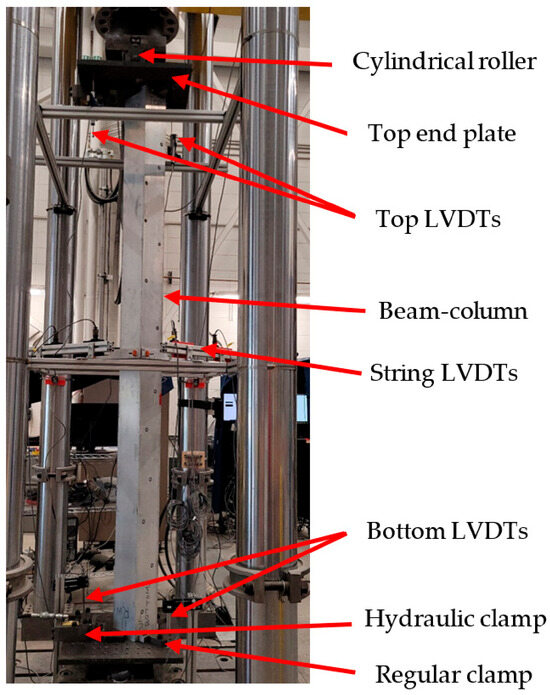
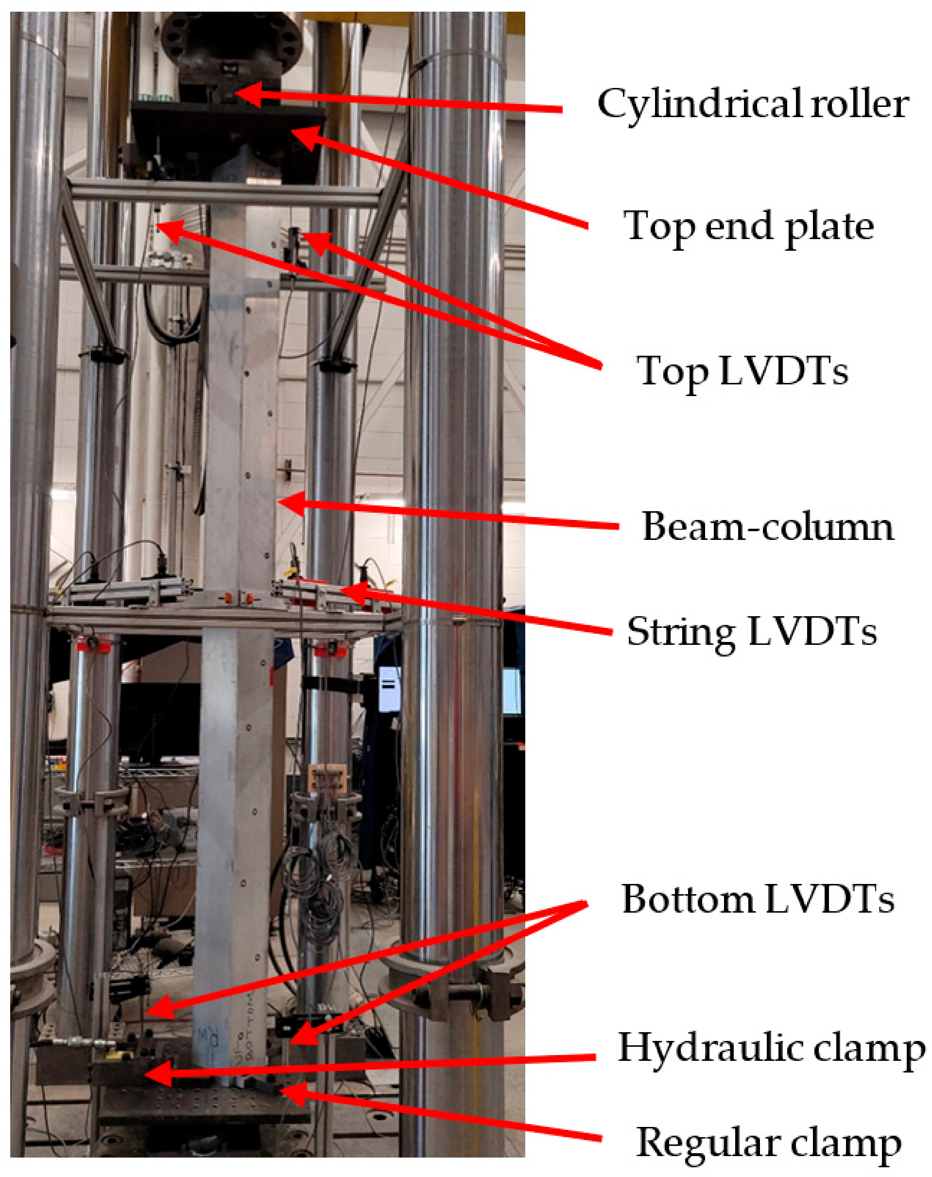
Prior to the member tests, tensile coupon tests and geometric imperfection measurements were carried out to characterize the material and geometric properties of the specimens. Figure 1 illustrates the experimental setup adopted for the eccentric compression tests. The beam-column tests were performed in an MTS servo-hydraulic frame using nominally pinned end conditions provided by cylindrical rollers and end plates. The load was introduced through prescribed eccentricities, and the response was monitored using end-shortening, lateral-displacement, twist and strain measurements. All tests were conducted under displacement control and continued into the post-peak range to capture the full buckling response. The resulting database provides the experimental basis for the FE model validation presented in Section 2.3.
Figure 1.
Experimental setup.
2.2. Finite Element Model Development
Finite element (FE) models were developed in Abaqus [13] to simulate the response of extruded aluminum SHS/RHS beam-columns. The members were discretized using four-node shell elements with reduced integration (S4R), which are well suited for capturing local plate buckling and post-buckling response in thin-walled members. Residual stresses and warping effects were neglected, which is reasonable for extruded closed hollow sections and consistent with the adopted fork-support idealization. For the validation models, the measured stress–strain curves of the tested specimens were used; for the broader numerical study, the material response was represented by a Ramberg–Osgood model [14] implemented in Abaqus through true stress-logarithmic plastic strain input.
Idealized pin-ended boundary conditions were adopted to remain consistent with beam-column design assumptions. The end cross-sections were constrained through kinematic couplings to enforce a plane-section response and to avoid local end distortions. Axial compression was applied under displacement control, and the ultimate resistance, , was taken as the peak load along the equilibrium path. For each configuration, a linear buckling analysis (LBA) was first performed to obtain elastic critical loads and mode shapes, followed by geometrically and materially non-linear analysis with imperfections (GMNIA) using the Riks method to trace the post-buckling response.
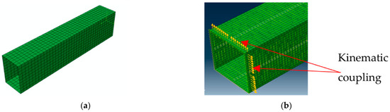
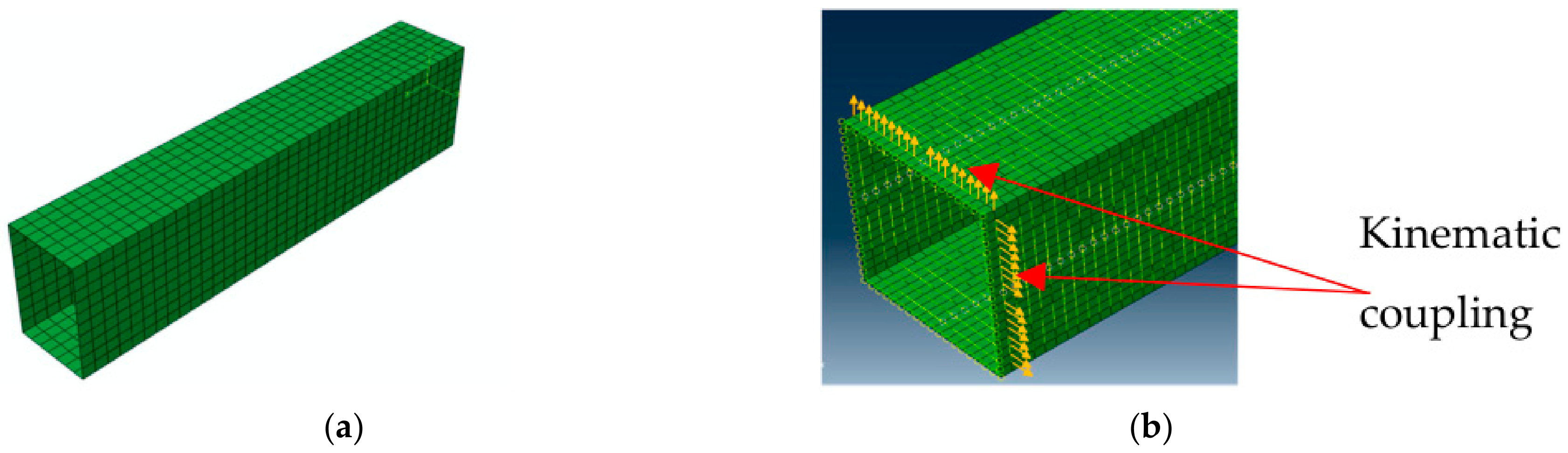
Two modelling strategies were considered, as illustrated in Figure 2. The first configuration, referred to as the local + global model, corresponds to the conventional shell model in which both local plate buckling and overall member flexural buckling are allowed to develop simultaneously. In this model, the initial imperfection field combines local wall imperfections and global member curvature, thereby permitting interaction between local and global instability modes.
Figure 2.
Finite element modelling strategies: (a) conventional local + global shell model; (b) global-only model with kinematic constraints used to suppress local plate buckling.
The second configuration, referred to as the global-only model, was developed to isolate the overall member instability response. As illustrated in Figure 2b, additional kinematic constraints were introduced all along the member length to suppress local wall deformations while preserving the global flexural behaviour of the member. This modelling strategy enables the extraction of the global beam-column response without local plate buckling effects and was used for the preliminary O.I.C.-based assessment.
2.3. Validation Against Tests
The FE modelling strategy was validated against five long-member tests on extruded aluminum SHS/RHS beam-columns conducted at Université Laval. The tested specimens covered different cross-sections, lengths and eccentric loading cases producing combined compression and bending. The numerical models incorporated the measured material response and scanned geometric imperfections of the test specimens, while the experimental eccentric loading was reproduced consistently in the analyses.
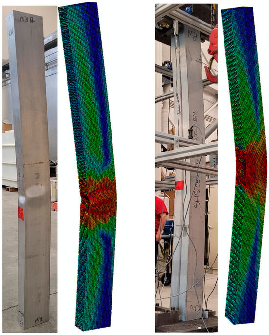
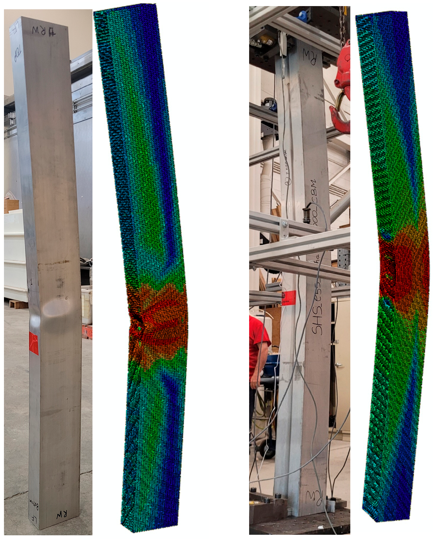
Representative comparisons are shown in Figure 3, where good agreement is observed in terms of stiffness, ultimate load, post-peak response and deformation mode. Table 2 shows that the ratio ranged from 0.94 to 1.06, with a mean of 1.01 and a coefficient of variation of 4.6%. The FE model is therefore considered sufficiently accurate for the subsequent parametric study and preliminary O.I.C.-based design evaluation.
Figure 3.
Validation of failure modes.
Table 2.
Validation results—mean and CoV.
3. Parametric Studies
3.1. Mesh and Imperfection Sensitivity Studies
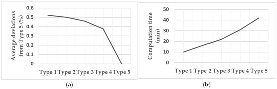
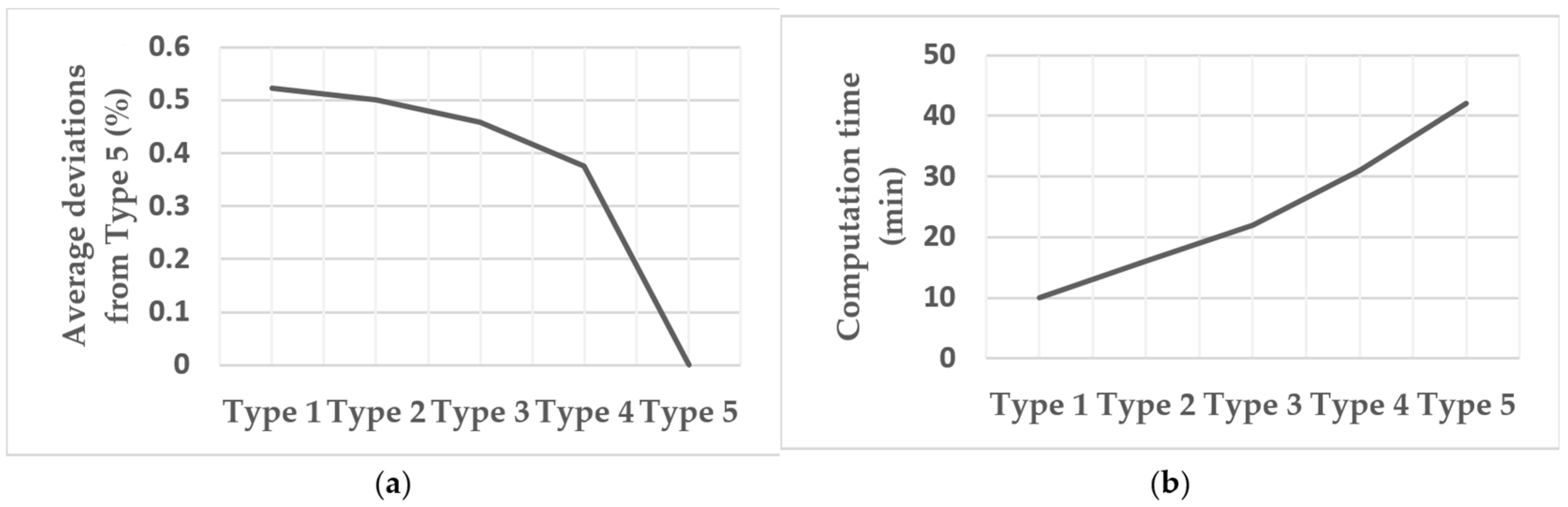
A mesh sensitivity study was first performed on nine representative members spanning Classes 1–3 and minor-axis relative slenderness values of 0.3, 1.2, and 2.4. Five shell meshes (Types I–V) were assessed by comparing the predicted ultimate resistances with those obtained using the finest mesh (Type V). Here, Type I corresponds to the coarsest shell discretization and Type V to the finest, with progressively increasing mesh refinement from Type I to Type V. The average deviation remained small, not exceeding 0.6%, whereas the computational cost increased substantially with mesh refinement, as shown in Figure 4. Since Type III produced an average deviation of only about 0.1%, it was selected for the subsequent parametric study as an efficient and sufficiently accurate mesh.
Figure 4.
Mesh sensitivity results: (a) deviation from Type 5; (b) computation time.
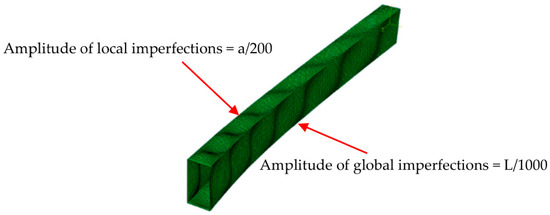
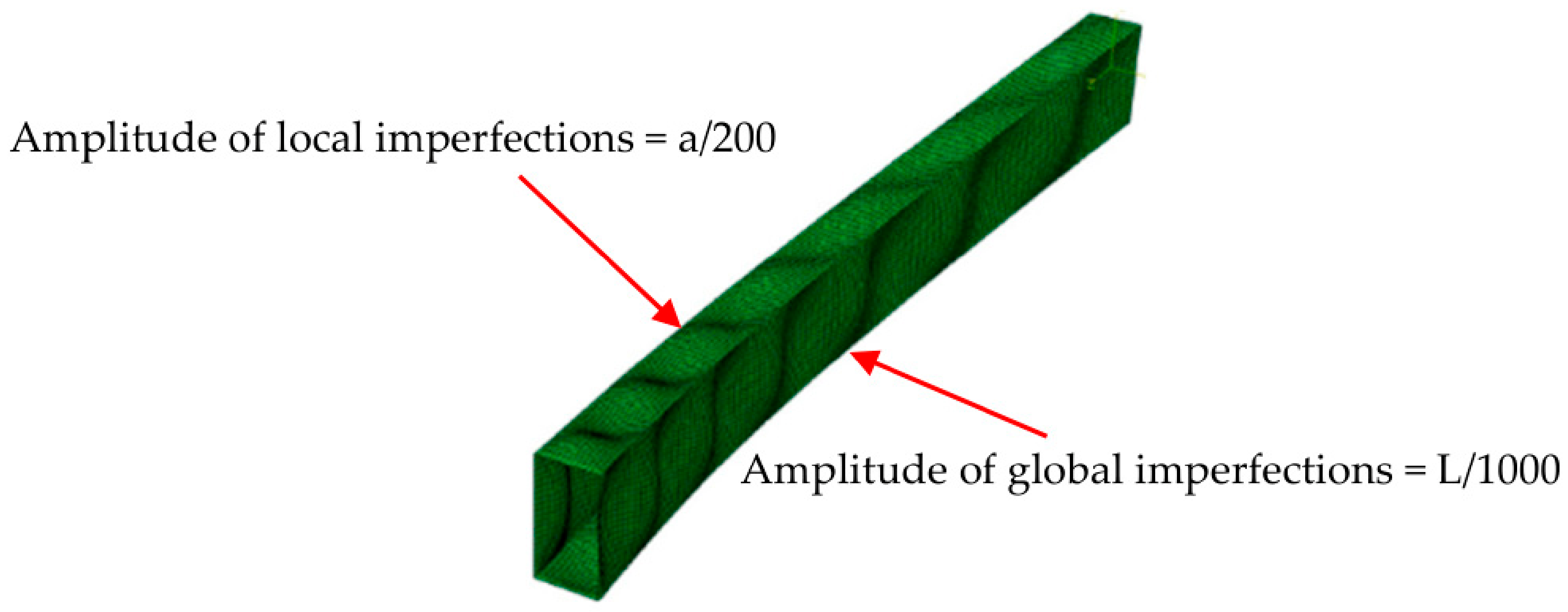
A preliminary geometric imperfection sensitivity study was also carried out to define a consistent imperfection model for the parametric analyses. Local and global imperfections were introduced using sinusoidal half-wave shapes. The local imperfection amplitude was fixed at , where is the flat plate width, following Dahboul et al. (2025) [11], while the global imperfection amplitude was varied as , , and , where is the member length. For each global amplitude, five local–global combinations were examined: 100%L + 100%G, 70%L + 100%G, 100%L + 70%G, 50%L + 100%G, and 100%L + 50%G. Based on this preliminary study, the combination 100%L + 100%G with a global imperfection amplitude of was adopted for the subsequent parametric analyses, while the local imperfection amplitude remained fixed at . Figure 5 illustrates the combined local and global imperfection pattern introduced in the FE model, shown with amplified deformations for visualization purposes.
Figure 5.
Representation of combined global and local geometrical imperfections introduced in FE model (magnified view).
3.2. Numerical Parametric Study
Comprehensive finite element parametric studies were performed using the validated shell models to investigate the buckling behaviour of extruded aluminum tubular members under compression and combined compression and bending. The numerical program considered 13 sharp-corner cross-sections, including eight RHS and five SHS profiles, selected to cover a broad range of section slenderness from compact to slender. Three aluminum alloys were included, namely 6061-T6, 6063-T6, and 6082-T6. The member lengths were chosen to represent eight minor-axis relative slenderness values, ranging from 0.3 to 2.4.
The load cases considered in the member study were axial compression (), compression plus uniaxial bending (), and compression plus biaxial bending (). For the beam-column cases, both constant bending moment (CBM) and triangular bending moment (TBM) distributions were investigated. In addition, cross-section capacity results from Dahboul et al. [11] were used, where required, to support the broader design-oriented assessment. For each member configuration, linear buckling analyses (LBAs) were first carried out to determine the elastic critical resistance, followed by geometrically and materially non-linear with imperfections analyses (GMNIAs) to obtain the ultimate resistance and post-buckling response. Both local + global and global-only modelling configurations were employed in the member simulations.
Overall, the full numerical campaign comprised more than 10,000 simulations. This database forms the basis for the preliminary resistance trends and design-oriented observations presented later in the paper.
4. Results and Discussions
4.1. Design Under Pure Compression
The pure compression results were interpreted within the Overall Interaction Concept (O.I.C.) framework, which treats local and global buckling within a unified design approach. In this framework, the plastic compression resistance of the cross-section, , together with the elastic critical local and global buckling loads, and , are used to define the corresponding relative slenderness values, and . The associated reduction factors, and , are then obtained from the Ayrton–Perry-type formulation [15] given in Equation (1), and the compression resistance is expressed as , where accounts for local–global interaction.
where
The FE compression database was expressed in a - format, and separate design curves were defined for local buckling and global buckling. For local buckling, the cross-sectional design curve was adopted from Dahboul et al. [11], rather than recalibrated in the present study. As summarized in Table 3, the retained parameters are and , while the imperfection factor is expressed as , with
Table 3.
OIC design parameters for local and global buckling.
This local formulation provides a simple continuous description of the influence of section slenderness and is taken to be common to the three alloys considered here.
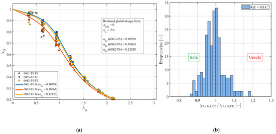
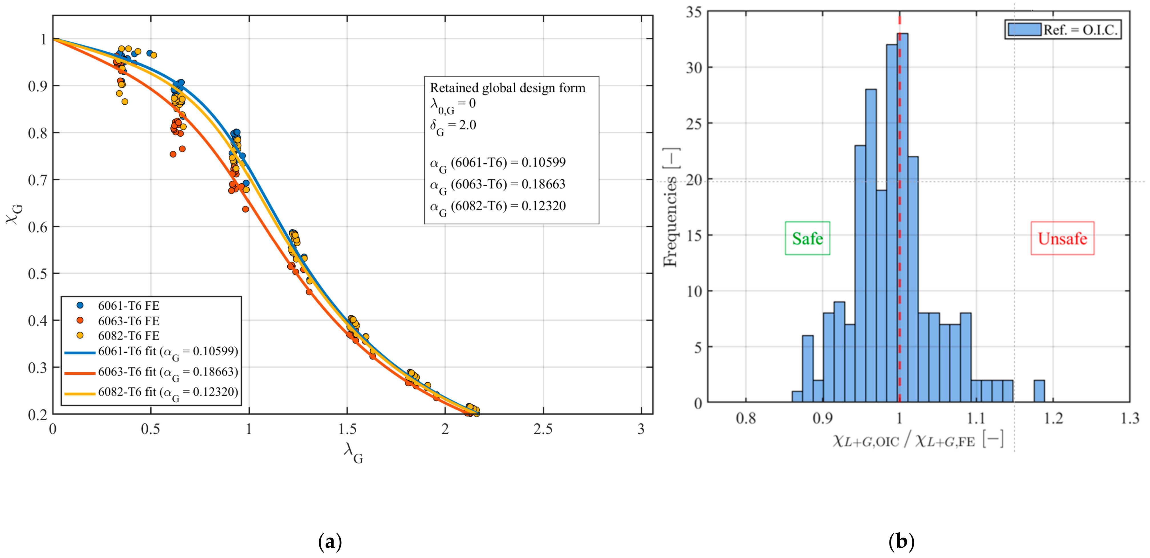
For global buckling, the member design curves were calibrated from the present FE compression results. The calibration yielded values of very close to zero for all three alloys; accordingly, was retained in the final formulation for simplicity. In addition, was adopted for all alloys, while the calibrated imperfection factors were for 6061-T6, for 6063-T6, and for 6082-T6. The complete set of retained Ayrton–Perry parameters is given in Table 3, and the resulting global buckling curves are compared with the FE data in Figure 6a.
Figure 6.
(a) O.I.C. curve calibration. (b) Comparison between O.I.C. and FE. The red dashed vertical line indicates the reference value of 1.0, corresponding to perfect agreement between the O.I.C. predictions and the FE results.
The proposed O.I.C.-based compression design was then assessed by comparing the predicted and FE-based local–global reduction factors. As shown in Figure 6b, the ratio is centred close to unity (red dashed line), with a mean of 0.992, COV of 5.5%, minimum of 0.861, and maximum of 1.187. Overall, these results indicate that the proposed formulation provides a satisfactory preliminary representation of the pure compression resistance of aluminum SHS/RHS members. The calibration will be refined further using the expanded database in the subsequent journal paper.
4.2. Beam-Column Behaviour
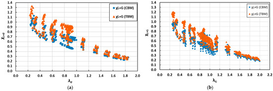
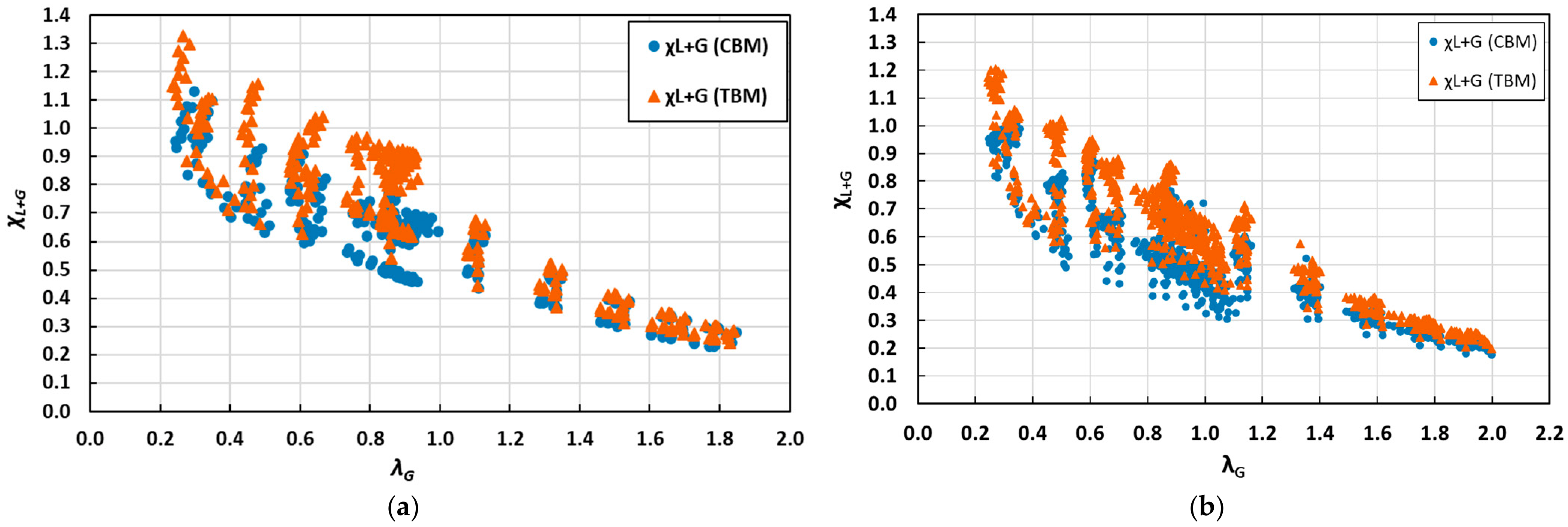
Preliminary results were obtained for members under combined loading, considering and cases, as shown in Figure 7a,b. The results are presented as scatter plots of versus , including both constant (CBM) and triangular (TBM) bending moment distributions. Only representative subsets of the database are shown for clarity.
Figure 7.
Scatter plots: (a) case; (b) case.
For the case (Figure 7a), a clear decreasing trend of with increasing is observed, similar to pure compression, but with noticeable dispersion in the intermediate slenderness range due to axial-bending interactions. Differences between CBM and TBM results highlight the influence of moment distribution.
For the case (Figure 7b), the scatter increases further, reflecting the added complexity of biaxial bending and enhanced local–global interaction effects. Despite this, the overall trend remains consistent across the slenderness range.
These results confirm that, although the general behaviour follows the same trends as pure compression, beam-column response exhibits increased variability that requires dedicated calibration. The results are therefore presented as preliminary, with a full calibration and statistical assessment to be addressed in a subsequent journal publication.
5. Conclusions
This study presented an experimental and numerical investigation of extruded aluminum SHS and RHS members under compression and combined loading. Five long-member tests were used to validate shell finite element models, showing very good agreement (mean ). A parametric study covering a wide range of sections, alloys, slenderness, and loading conditions was then performed. Mesh and imperfection sensitivity analyses led to the adoption of a Type III mesh and combined local and global imperfections (, ). For pure compression, the results were successfully interpreted within the Overall Interaction Concept (O.I.C.) framework, with preliminary calibration providing a satisfactory representation of the numerical data.
For combined loading ( and ), the preliminary results highlighted increased dispersion due to moment distribution and biaxial bending effects. While overall trends remain consistent, dedicated calibration is required. The results confirm the potential of the O.I.C. approach as a unified design framework, with further work ongoing to refine the calibration and develop practical design expressions.
Author Contributions
Conceptualization, P.V. and N.B.; methodology, P.V. and N.B.; laboratory experiments, P.V. and S.D.; formal analysis, P.V.; investigation, P.V. and S.D.; resources, P.V. and S.D.; data curation, P.V.; writing—original draft preparation, P.V.; writing—review and editing, P.V., P.D. and N.B.; visualization, P.V.; supervision, P.D. and N.B.; project administration, P.D. and N.B.; funding acquisition, P.D. and N.B. All authors have read and agreed to the published version of the manuscript.
Funding
This research was funded by “Fonds de Recherche du Québec—NATURE ET TECHNOLOGIE (FRQNT)—FT131760”.
Institutional Review Board Statement
Not applicable.
Informed Consent Statement
Not applicable.
Data Availability Statement
The original contributions presented in this study are included in the article. Further inquiries can be directed to the corresponding author.
Conflicts of Interest
The authors declare no conflict of interest.
References
- Beaulieu, D. Design of Aluminium Structures; La Presse de L’aluminium: Chicoutimi, QC, Canada, 2006; ISBN 2-923168-08-9. [Google Scholar]
- Mazzolani, F.M. (Ed.) Aluminium Structural Design; Springer: Vienna, Austria, 2003; ISBN 978-3-211-00456-2. [Google Scholar]
- European Committee for Standardization (CEN). EN 1999-1-1: Eurocode 9: Design of Aluminium Structures—Part 1-1: General Structural Rules; CEN: Brussels, Belgium, 2009. [Google Scholar]
- The Aluminum Association. Aluminum Design Manual; The Aluminum Association: Arlington, VA, USA, 2020. [Google Scholar]
- Canadian Standards Association. CSA S157-17: Strength Design in Aluminum; CSA: Toronto, ON, Canada, 2017; ISBN 978-1-4883-0709-6. [Google Scholar]
- Li, B.; Wang, Y.; Zhi, X.; Zhang, Y.; Baniotopoulos, C.C. Testing, modelling and design of 7A04-T6 high-strength aluminium alloy RHS columns under axial compression. J. Build. Eng. 2022, 57, 104910. [Google Scholar] [CrossRef] [Scilit]
- Hu, Y.; Rong, B.; Zhang, R.; Zhang, Y.; Zhang, S. Study of buckling behavior for 7A04-T6 aluminum alloy rectangular hollow columns. Thin-Walled Struct. 2021, 169, 108410. [Google Scholar] [CrossRef] [Scilit]
- Wang, Z.X.; Wang, Y.Q.; Sojeong, J.; Ouyang, Y.W. Experimental investigation and parametric analysis on overall buckling behavior of large-section aluminum alloy columns under axial compression. Thin-Walled Struct. 2018, 122, 585–596. [Google Scholar] [CrossRef] [Scilit]
- Zhu, J.H.; Young, B. Behavior and design of aluminum alloy structural members. Int. J. Adv. Steel Constr. 2008, 4, 158–172. [Google Scholar] [CrossRef] [Scilit]
- Li, H.; Peng, Y.; Huang, Y.; Zhong, C. Design of 6013-T6 aluminum alloy SHS and RHS columns at elevated temperatures. J. Constr. Steel Res. 2026, 243, 110426. [Google Scholar] [CrossRef] [Scilit]
- Dahboul, S.; Verma, P.; Li, L.; Dey, P.; Boissonnade, N. O.I.C.-based design of extruded aluminium rectangular hollow sections under simple load cases. Structures 2025, 79, 109510. [Google Scholar] [CrossRef] [Scilit]
- Ban, H.; Shi, G. Overall buckling behaviour and design of high-strength steel welded section columns. J. Constr. Steel Res. 2018, 143, 180–195. [Google Scholar] [CrossRef] [Scilit]
- Dassault Systèmes. Abaqus Analysis User’s Guide (Version 6.14); Dassault Systèmes: Providence, RI, USA, 2014. [Google Scholar]
- Ramberg, W.; Osgood, W.R. Description of Stress–Strain Curves by Three Parameters; NACA Technical Note.902; National Advisory Committee for Aeronautics: Washington, DC, USA, 1943. [Google Scholar]
- Ayrton, W.E.; Perry, J. On Struts. Engineer 1886, 62, 464–465. [Google Scholar]

Disclaimer/Publisher’s Note: The statements, opinions and data contained in all publications are solely those of the individual author(s) and contributor(s) and not of MDPI and/or the editor(s). MDPI and/or the editor(s) disclaim responsibility for any injury to people or property resulting from any ideas, methods, instructions or products referred to in the content. |
© 2026 by the authors. Licensee MDPI, Basel, Switzerland. This article is an open access article distributed under the terms and conditions of the Creative Commons Attribution (CC BY) license.