


Abstract
The end-to-end design and successful integration of a low-voltage educational electric vehicle (EV) built around a Controller Area Network (CAN) backbone is presented in this study. Its reproducible system architecture was built on a unified message specification database, and a set of bring-up and diagnostic procedures enables students to assemble, validate, and extend an EV using commodity controllers. The vehicle was manufactured and commissioned with classic-CAN operating at 250–500 kbps, integrating traction, battery management system, dashboard, lighting, and safety nodes. Initial tests confirmed reliable messaging and error-free operation under typical campus driving conditions. In addition, an upgrade path to CAN with flexible data-rate and 100BASE-T1 Ethernet is provided for future curricula. The platform reduces integration complexity, shortens fault-finding, and supports multidisciplinary teaching across mechanical engineering, electrical and computer engineering, and computer science.
1. Introduction
The rapid global shift toward electrified transportation necessitates a fundamental change in engineering education to prepare graduates for complex electric vehicle (EV) architectures [1]. Traditional curricula often lack hands-on experience in distributed embedded systems, which form the core of modern EVs [2]. High-voltage architectures pose significant safety and cost barriers in academic settings, justifying the strategic selection of a low-voltage (LV) EV platform to focus instructional efforts on control algorithms and system-level communication [3].
The Controller Area Network (CAN) protocol is a standard for in-vehicle communication, making its practical mastery a prerequisite for engineers entering the automotive industry [4]. This paper addresses the educational gap by presenting a comprehensive, reproducible EV platform built on a classic-CAN backbone. The work introduces three key educational contributions: a simplified, multi-domain system architecture; a unified communication database (DBC) [5]; and a rigorous, codified methodology for network commissioning and fault diagnosis [6]. We validate the system’s technical success through operational testing and confirm its pedagogical value as a multidisciplinary teaching tool [2].
2. Materials and Methods
The educational EV system was designed as a distributed embedded system composed of five electronic control units (ECUs) interconnected by a Classic-CAN (2.0B) network operation [4].
2.1. System Architecture and Component Selection
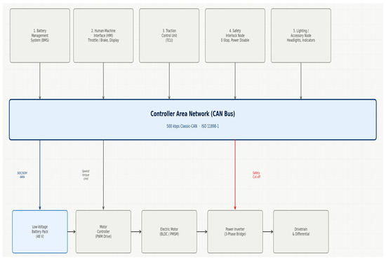
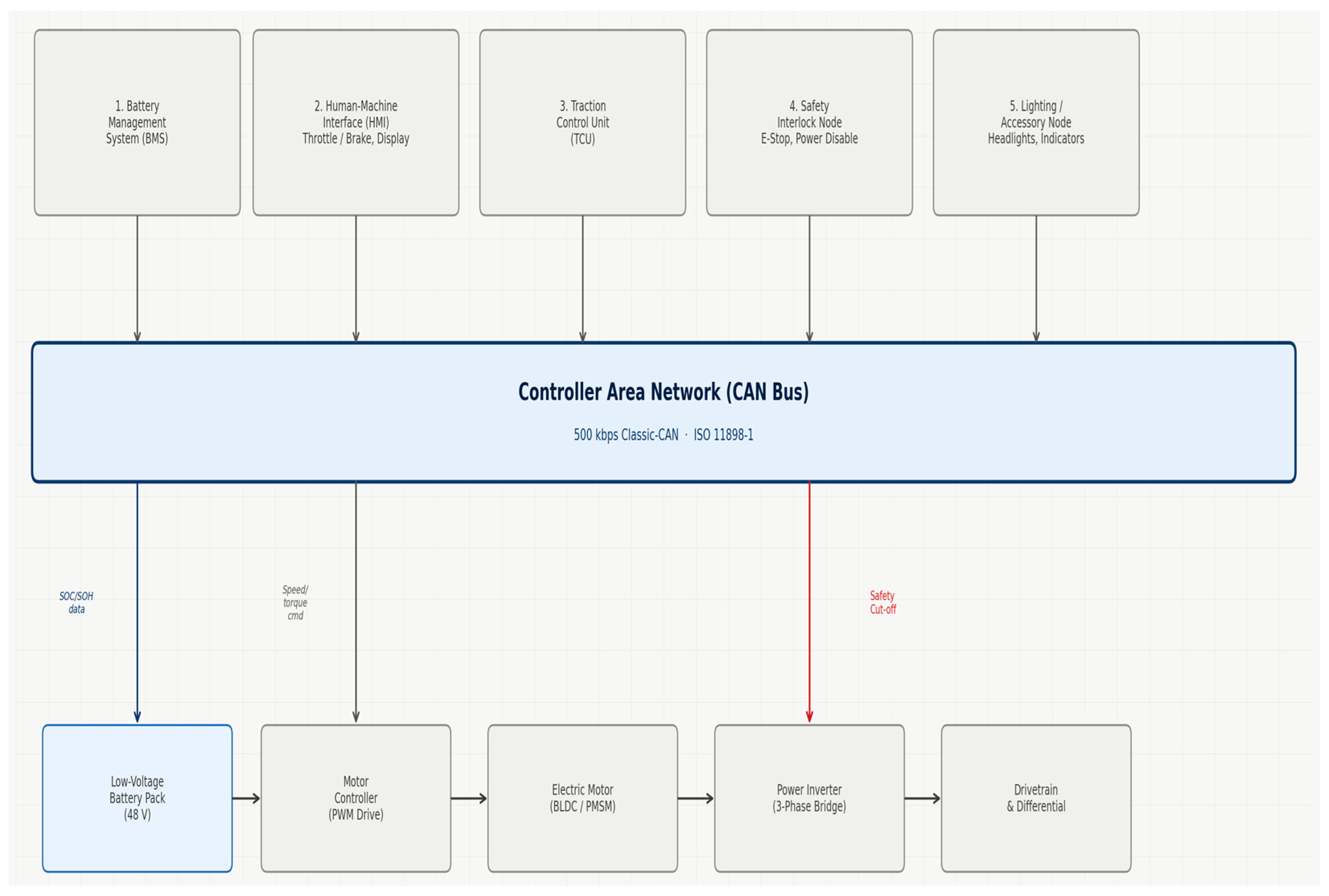
The platform utilizes an LVDC architecture, which reduces safety complexity and enables the use of widely available, commodity microcontrollers for their real-time performance and integrated CAN peripherals [7,8] (Figure 1). This selection ensures the platform is highly reproducible by other academic institutions [9]. The ECU functions are partitioned as follows.
Figure 1.
Block diagram illustrating the LV Educational EV architecture, showing the five ECUs interconnected using the shared CAN bus.
- Battery management system (BMS) Node: Monitors the state-of-charge (SOC), state-of-health (SOH), and thermal/voltage limits of the battery pack [10].
- Traction control unit (TCU): Processes driver torque requests and BMS limits to execute the motor control algorithms [8].
- Human–machine interface (HMI) Node: Serves as the driver interface for throttle/brake input and displays vehicle status data received via the CAN bus [11].
- Safety interlock node: A dedicated, high-priority node for monitoring critical safety features (e.g., E-Stop) and commanding power disablement [11].
- Lighting/accessory node: Manages low-priority accessory functions [11].
The overall integration of these subsystems is conceptually detailed in Figure 1, illustrating the centralized nature of the CAN backbone.
2.2. Classic-CAN Implementation and Topology
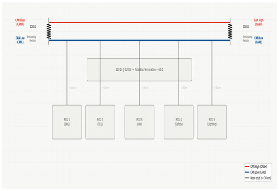
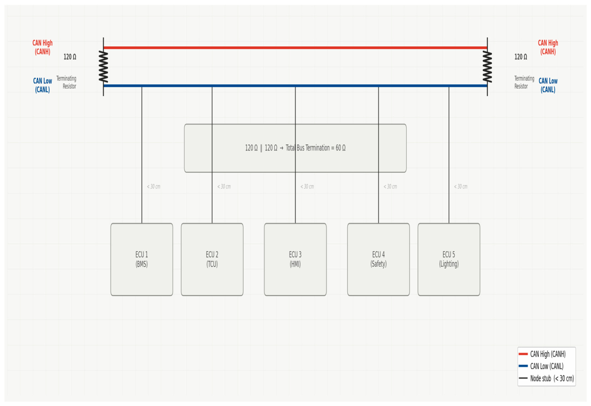
The network employs a linear bus topology, which is physically and logically the simplest configuration [11]. Maintaining signal integrity is achieved by adhering to strict physical layer requirements, as shown in Figure 2.
Figure 2.
Schematic of the Classic-CAN Bus physical layer topology, illustrating the linear bus structure, the twisted pair wiring (CAN High and CAN Low), and the necessary terminating resistors at the two endpoints, ensuring a total bus resistance.
- Termination: The bus requires precise termination at exactly two end nodes using resistors wired in parallel, yielding a total bus resistance [6].
- Wiring: Communication utilizes a twisted pair of wires [CAN High (CAN-H) and CAN Low (CAN-L)] to maximize noise immunity through a differential signal [12]. Stub lengths (taps off the main bus line to each ECU) were constrained to less than at to minimize signal reflections [6].
2.3. DBC
All communication properties are formalized in a standardized CAN Database (DBC) file, which acts as the communication contract between ECUs [5]. The DBC specifies the arbitration ID, cycle time, transmitting node, and the signal scaling required to convert raw data bytes into engineering units [5]. A priority scheme was established where lower numerical IDs are assigned to time-critical safety and control messages to ensure deterministic access to the shared bus, as summarized in Table 1 [13].
Table 1.
Excerpt of standardized DBC message specification (critical functions).
3. Results
3.1. Physical Layer Commissioning Results
The platform was validated in two phases: mandatory physical layer commissioning checks and dynamic operational testing (Figure 3). First, students were required to perform physical and electrical checks using a digital multimeter (DMM) before network activation [6]. These reproducible procedures successfully identified and corrected common wiring faults, confirming adherence to best practices.
Figure 3.
Real-time image of the connections of CAN bus system.
- Termination resistance: The measured resistance across CAN-H and CAN-L (with power off) at any point on the bus was consistently verified [6]. Readings of (missing termination) or (extra termination) were immediately detected and corrected [14].
- Idle voltage measurement: With power applied and the bus idle (no active data transmission), the DC voltage measured between CAN-H and ground, and CAN-L and ground, consistently approximated [15]. This confirmed stable power delivery and the absence of hard shorts to power or ground on either line [16].
3.2. Dynamic Operation and Reliability Testing
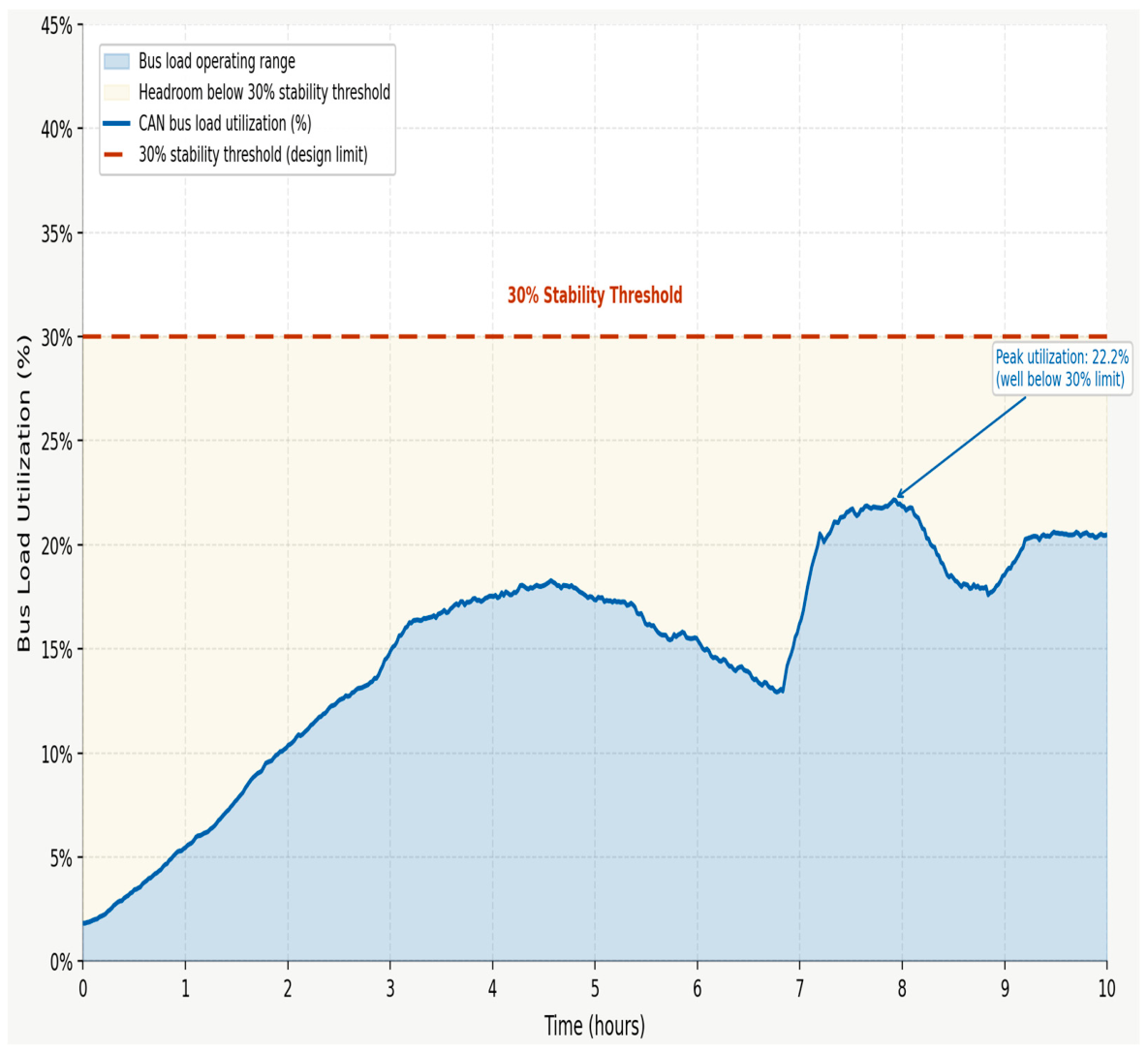
The fully commissioned EV was subjected to dynamic testing simulating a typical campus driving profile, involving frequent changes in speed and load [17]. Network performance was logged over 10 h of operation.
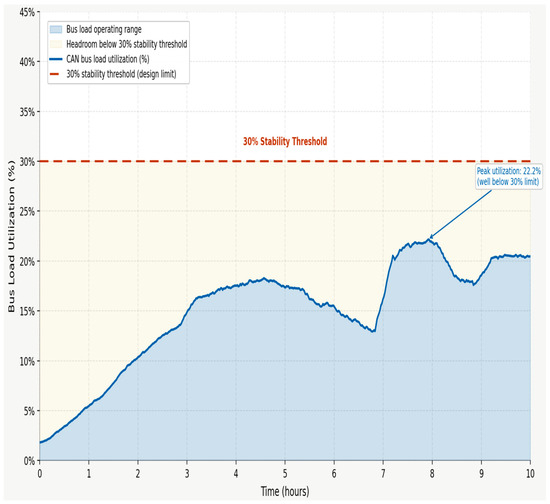
- Bus load and determinism: Under peak operational conditions, the network utilization remained consistently below the capacity [18]. Maintaining a low bus load is a crucial result, as it ensures that the priority-based arbitration scheme remains effective, guaranteeing low communication delay for time-critical control messages (e.g., torque commands) [18]. The load profile observed is summarized in Figure 4.
- Error frame ratio (EFR): The definitive measure of network reliability is the EFR [19]. Over the entire 10 h dynamic test period, the system recorded an EFR of error frames per 10,000 transmitted frames. This result confirms the robust integrity of the student-assembled physical wiring and communication configurations under real-world operating conditions [19].
- Signal consistency: Critical signals, such as the battery state-of-health (SOH), were monitored across varied driving states. Consistent SOH readings, which are independent of short-term factors like charge level or immediate vehicle demand, validated the stability of the BMS node and the error-free transmission of its data [20].
Figure 4.
Graph illustrating the CAN Bus load utilization rate (%) over the 10 h dynamic operational test cycle, demonstrating the network-maintained stability below the threshold.
4. Discussion
4.1. Pedagogical Value and Multidisciplinary Outcomes
The platform’s success validates its role as a key mechanism for multidisciplinary education in mechanical engineering (ME), electrical/computer engineering (ECE), and computer science (CS) [2]. The use of the DBC file acts as a universal specification that mandates collaboration.
- Students majoring in ME use CAN data to validate physical design concepts, such as evaluating the efficacy of regenerative braking based on transmitted power consumption signals [19].
- Students majoring in ECE gain critical hands-on experience in embedded systems programming, real-time control, and, importantly, the use of physical diagnostic tools (DMMs, analysers) to troubleshoot wiring faults, an essential skill often neglected in purely theoretical courses [6].
- Students majoring in CS leverage the DBC definition to develop the higher-level software stacks, including diagnostic and data logging applications that parse raw CAN frames into meaningful data, preparing them for software-defined vehicle architectures.
4.2. Future Work: Network Evolution and Cybersecurity
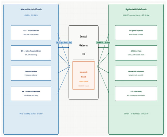
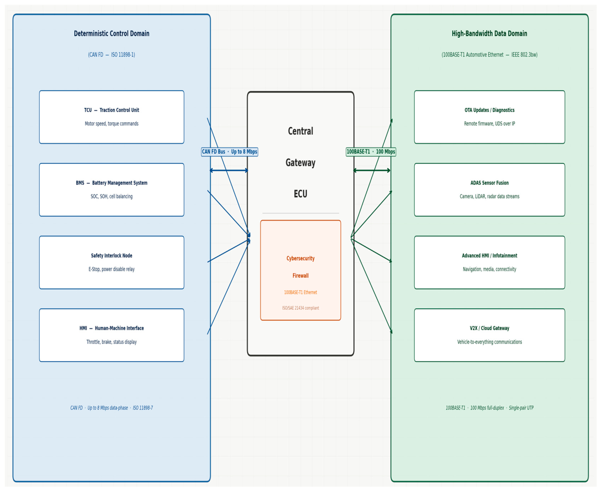
While Classic-CAN proved reliable for this LV platform, its bandwidth constraints require a defined upgrade strategy to maintain curriculum relevance. The future roadmap involves a transition to a segmented network architecture, illustrated conceptually in Figure 5.
Figure 5.
Future architecture roadmap: segmented network diagram showing the co-existence of the deterministic CAN FD domain (control) and the high-bandwidth 100BASE-T1 Automotive Ethernet domain (Data), connected using a central Gateway ECU.
- CAN flexible data-rate (FD) upgrade: Migrating to CAN FD (up to 64-byte payloads) allows students to explore higher throughput for bulk data transfer (e.g., enhanced diagnostics) while preserving the deterministic, priority-based arbitration of CAN.
- 100BASE-T1 automotive Ethernet integration: For high-bandwidth applications, the integration of 100BASE-T1 using a Gateway ECU is planned. This shift introduces students to switched, point-to-point topologies, facilitating new curriculum modules on Diagnostics over Internet Protocol and the critical need for network segmentation, firewalls, and security protocols such as Media Access Control Security to address modern automotive cybersecurity requirements (the United Nations Economic Commission for Europe World Forum for Harmonization of Vehicle Regulations WP.29).
5. Conclusions
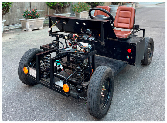
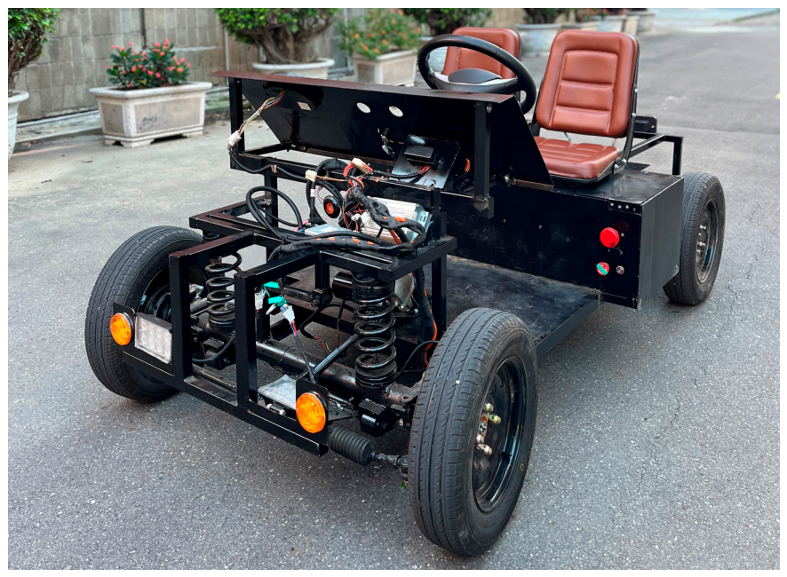
We developed and validated a reproducible low-voltage educational EV platform utilizing a Classic-CAN backbone. The standardized DBC specification and mandated physical layer diagnostic procedures proved highly effective in achieving communication stability, confirming error-free performance under dynamic operation. The platform is confirmed as a robust tool that supports hands-on learning across ME, ECE, and CS disciplines, providing a critical foundation in complex distributed vehicular networks (Figure 6). It is necessary to integrate CAN FD and 100BASE-T1 to prepare students for the advanced bandwidth and cybersecurity challenges of next-generation EV architectures.
Figure 6.
Educational EV developed in this study.
Author Contributions
Conceptualization, J.-J.T. and S.B.J.B.S.; methodology, J.-J.T.; software, P.-R.L.; validation, J.-J.T., S.B.J.B.S. and P.-R.L.; formal analysis, J.-J.T.; investigation, S.B.J.B.S.; resources, J.-J.T.; data curation, P.-R.L.; writing—original draft preparation, S.B.J.B.S.; writing—review and editing, J.-J.T.; visualization, P.-R.L.; supervision, J.-J.T.; project administration, J.-J.T. All authors have read and agreed to the published version of the manuscript.
Funding
This research received no external funding.
Institutional Review Board Statement
Not applicable.
Informed Consent Statement
Not applicable.
Data Availability Statement
No new data were created or analyzed in this study. Data sharing is not applicable to this article.
Conflicts of Interest
The authors declare no conflicts of interest.
Abbreviations
The following abbreviations are used in this manuscript:
| ADAS | Advanced Driver-Assistance Systems |
| BMS | Battery Management System |
| CAN | Controller Area Network |
| CAN FD | CAN Flexible Data-Rate |
| CS | Computer Science |
| DBC | CAN Database File |
| DMM | Digital Multimeter |
| ECE | Electrical and Computer Engineering |
| ECU | Electronic Control Unit |
| EFR | Error Frame Ratio |
| HMI | Human–Machine Interface |
| LV | Low-Voltage |
| ME | Mechanical Engineering |
| OTA | Over-The-Air |
| SOC | State-of-Charge |
| SOH | State-of-Health |
| TCU | Traction Control Unit |
References
- Syed, K.; M., V.; Kandakatla, R.; Narayanan, S. Inculcating Multidisciplinary Learning in Electrical Engineering Undergraduate Curriculum through Problem-Based Learning. J. Eng. Educ. Transform. 2024, 38, 210–215. [Google Scholar] [CrossRef] [Scilit]
- EV Trainer 3 in 1 Electric Vehicle Integrated Training System Educational Equipment. Available online: https://cngtee.en.made-in-china.com/product/uFWajDCvLTGy/China-EV-Trainer-3-in-1-Electric-Vehicle-Integrated-Training-System-Educational-Equipment.html (accessed on 6 October 2025).
- Seshan, N. Why Signal Isolation Matters in 48-V HEV/EV Systems. Texas Instruments. Available online: https://www.ti.com/document-viewer/lit/html/SSZT369 (accessed on 6 October 2025).
- Schreiner, T. Introduction of CAN FD into the next generation of vehicle E/E architectures. In Proceedings of the CAN-CIA, Nuremberg, Germany, 21–25 May 2017; Available online: https://can-cia.org/fileadmin/cia/documents/proceedings/2017_schreiner.pdf (accessed on 6 October 2025).
- LHP Engineering Solutions. What Are Electric Vehicle Subsystems and Their Interactions? Available online: https://www.lhpes.com/blog/what-are-electric-vehicle-subsystems-and-their-interactions (accessed on 6 October 2025).
- Texas Instruments. Achieving High Efficiency and Enabling Integration in EV Powertrain Subsystems Using C2000 Real-Time MCUs. Available online: https://www.ti.com/lit/sway033 (accessed on 6 October 2025).
- Vector. CANdb++ Admin. Available online: https://www.vector.com/candb-admin/ (accessed on 6 October 2025).
- Analog Devices. AN-1123: Controller Area Network (CAN) Implementation Guide. Analog Devices. Available online: https://www.analog.com/en/resources/app-notes/an-1123.html (accessed on 6 October 2025).
- National Instruments (NI). CAN Identifiers and Message Priority. Available online: https://www.ni.com/docs/en-US/bundle/ni-xnet/page/can-identifiers-and-message-priority.html (accessed on 6 October 2025).
- Horizon Connect. CAN Bus Limitations in Modern Connected Vehicles. Available online: https://horizonconnect.de/can-bus-limitations-connected-vehicles/ (accessed on 6 October 2025).
- Yng, H. How In-Vehicle Networking Bolsters Connectivity on the Road. Available online: https://www.keysight.com/blogs/en/tech/educ/2024/in-vehicle-networking (accessed on 6 October 2025).
- Falch, M. CAN Bus Explained—A Simple Intro [2026]. Available online: https://www.csselectronics.com/pages/can-bus-simple-intro-tutorial (accessed on 6 October 2025).
- Ruptela. How to Decode CAN Bus Data: A Practical Guide for Engineers. Available online: https://ruptela.com/decode-can-bus-messages-guide/ (accessed on 6 October 2025).
- Copperhill. CAN Bus Troubleshooting: A Technical Guide. Available online: https://copperhilltech.com/blog/can-bus-troubleshooting-a-technical-guide/ (accessed on 6 October 2025).
- Texas Instruments. Controller Area Network Physical Layer Requirements. Available online: https://www.ti.com/lit/pdf/slla270 (accessed on 6 October 2025).
- DBC Introduction. Open Vehicles Documentation. Available online: https://docs.openvehicles.com/en/latest/components/vehicle_dbc/docs/dbc-primer.html (accessed on 6 October 2025).
- Du, F.; Cai, Y.; Guan, Z.; Tang, F.; Wu, D.; Shi, H.; Wang, T. Investigation of real-time optimization based on CAN bus. J. Phys. Conf. Ser. 2021, 1735, 012005. [Google Scholar] [CrossRef] [Scilit]
- Grid Connect. How to Diagnose a Controller Area Network (CAN). Available online: https://www.gridconnect.com/blogs/news/how-to-diagnose-a-controller-area-network-can (accessed on 6 October 2025).
- Star Electronics. Troubleshooting and Problem-Solving Resources for CAN Bus. Available online: https://flex-product.com/knowledge/can-bus/troubleshooting-and-problem-solving (accessed on 6 October 2025).
- Enovation Controls. CAN BUS Troubleshooting Guide (with Video). Available online: https://support.enovationcontrols.com/hc/en-us/articles/360038856494-CAN-BUS-Troubleshooting-Guide-with-Video (accessed on 6 October 2025).

Disclaimer/Publisher’s Note: The statements, opinions and data contained in all publications are solely those of the individual author(s) and contributor(s) and not of MDPI and/or the editor(s). MDPI and/or the editor(s) disclaim responsibility for any injury to people or property resulting from any ideas, methods, instructions or products referred to in the content. |
© 2026 by the authors. Licensee MDPI, Basel, Switzerland. This article is an open access article distributed under the terms and conditions of the Creative Commons Attribution (CC BY) license.