


Abstract
The use of formwork in construction is crucial as structural support, and its success depends on proper design and calculations that meet standards and economic efficiency. This study analyzes formwork in the G building project. For plywood, Mu, Vu, and deflection (δ) are safe but inefficient due to high safety factors. In the first support beam, Mu and δ are safe and very efficient, while Vu is safe but inefficient. In the second support beam, Mu and Vu are safe and efficient, but δ is safe yet inefficient. Therefore, proper technical data and strength analysis are needed for optimal implementation.
1. Introduction
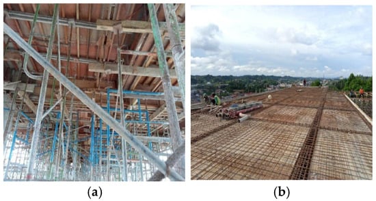
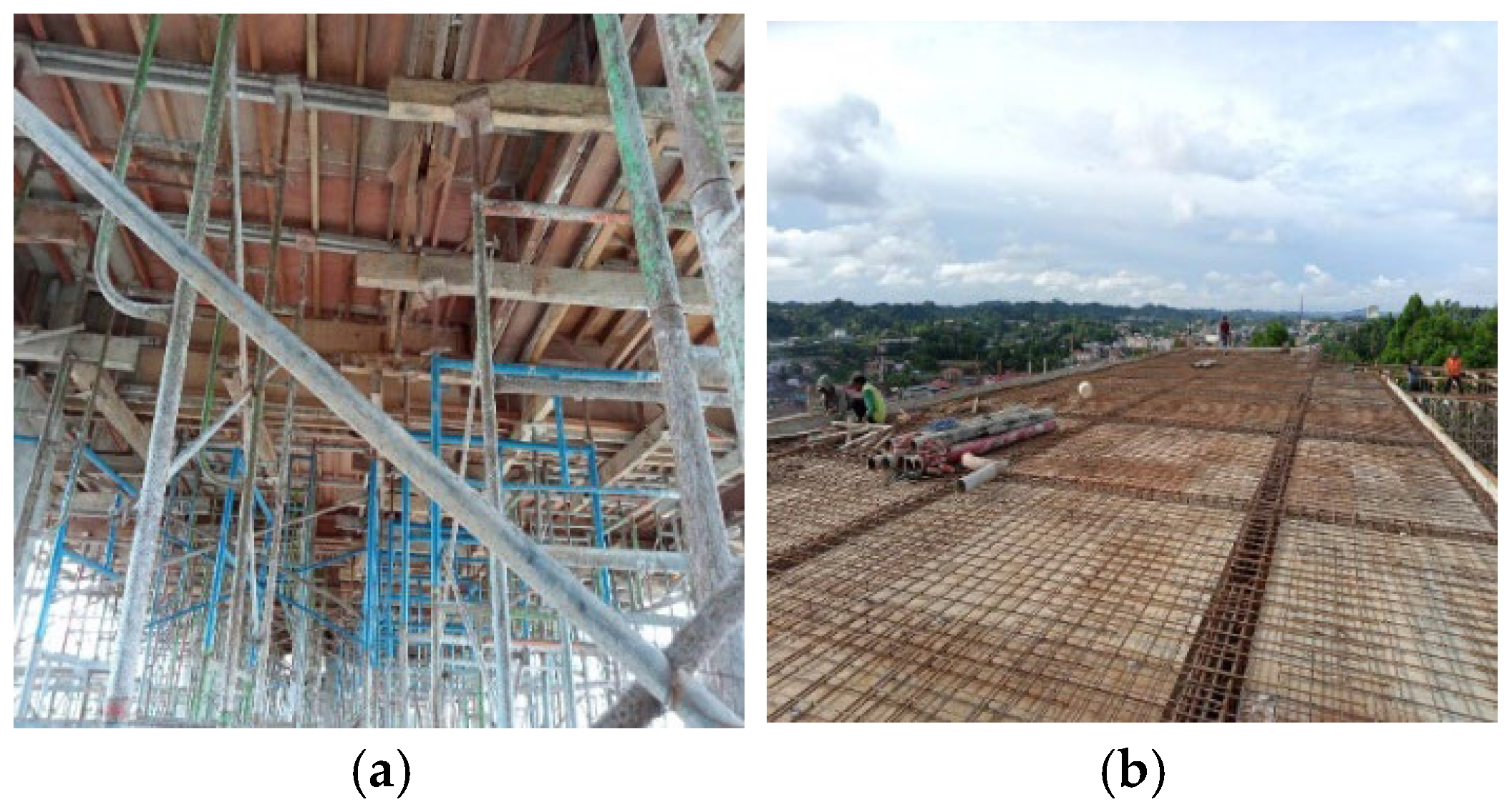
Formwork is a crucial supporting structure in concrete construction [1]. Formwork itself is used as a mold to shape the concrete and also as a support for the concrete itself [2]. There are two types of formwork, namely modern formwork made of iron and conventional formwork made of wood [3]. The types of formwork are more clearly shown in (Figure 1).
Figure 1.
(a) Modern formwork using iron and wood, (b) Conventional formwork.
In terms of cost, the use of semi-modern formwork is more efficient than using wooden formwork in terms of building area and number of floors [4]. According to Perwitasari, et. al., modern formwork is superior to conventional formwork because modern formwork uses durable materials [5,6]. In addition, it can be used repeatedly, thereby saving costs [7].
The types of wood used for formwork construction are meranti and pine. Meranti wood (Shorea leprosula Miq.) is a type of wood commonly used for housing, shipping, and furniture [8]. Meanwhile, pine wood (Pinus Merkusii) is a type of wood commonly used as furniture material and also has a high level of resistance to fungi [9].
A project is an activity aimed at achieving a specific end result for all parties involved [10]. In a project, it is often found that the construction contractor does not use technical rules (structural calculations) and only relies on previous work experience [11,12,13]. This has an impact on the uncertainty of the construction work in terms of both safety and efficiency [14,15]. The possible consequences of this construction are, first, unsafe construction, which can even lead to a risk of structural collapse [16]. Second, the construction may be safe and efficient, or safe but inefficient due to the excessive use of materials [17].
This paper analyzes the use of formwork construction materials in the construction project of the G Jenderal Sudirman building at the University of Muhammadiyah Kalimantan Timur. Observations of this project revealed that there was no analysis of formwork calculations for the installation of formwork construction, only working drawings.
2. Research Method
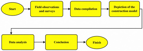
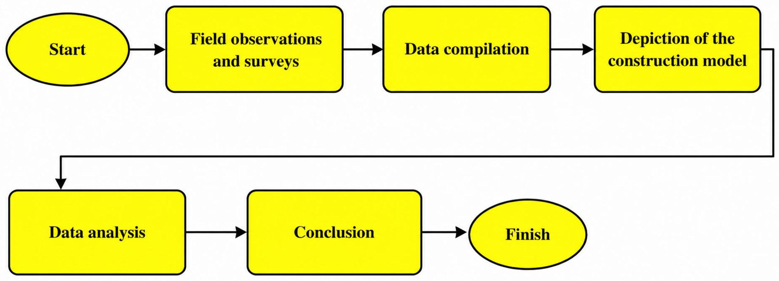
This paper is based on observations and field surveys in the form of construction data compiled into models, which were then used to create detailed technical drawings of formwork construction. Analysis was then conducted to determine the efficiency of formwork timber usage. This is illustrated in more detail in Figure 2 below.
Figure 2.
Research flow chart.
As seen in the flow chart of the above method, (Figure 2) the research begins with observation to complete the data and a direct survey in the field. Then, after the data has been obtained, it is combined from the data that has been collected and the image is redrawn. The combined data is then analyzed to see whether the material efficiency is wasteful or not.
To determine the efficiency of this formwork construction, criteria based on safety factor values are used, which are divided into several conditions as shown in Table 1 below.
Table 1.
Construction efficiency criteria.
3. Results and Discussion
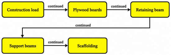
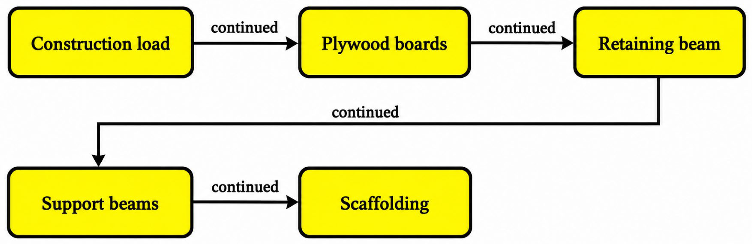
In the formwork installation, there is a load flow mechanism that is supported by plywood formwork, support beams, support timbers, and scaffolding (continued to the foundation) as shown in Figure 3, the load flow analysis flowchart below.
Figure 3.
Load flow analysis flow chart.
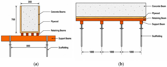
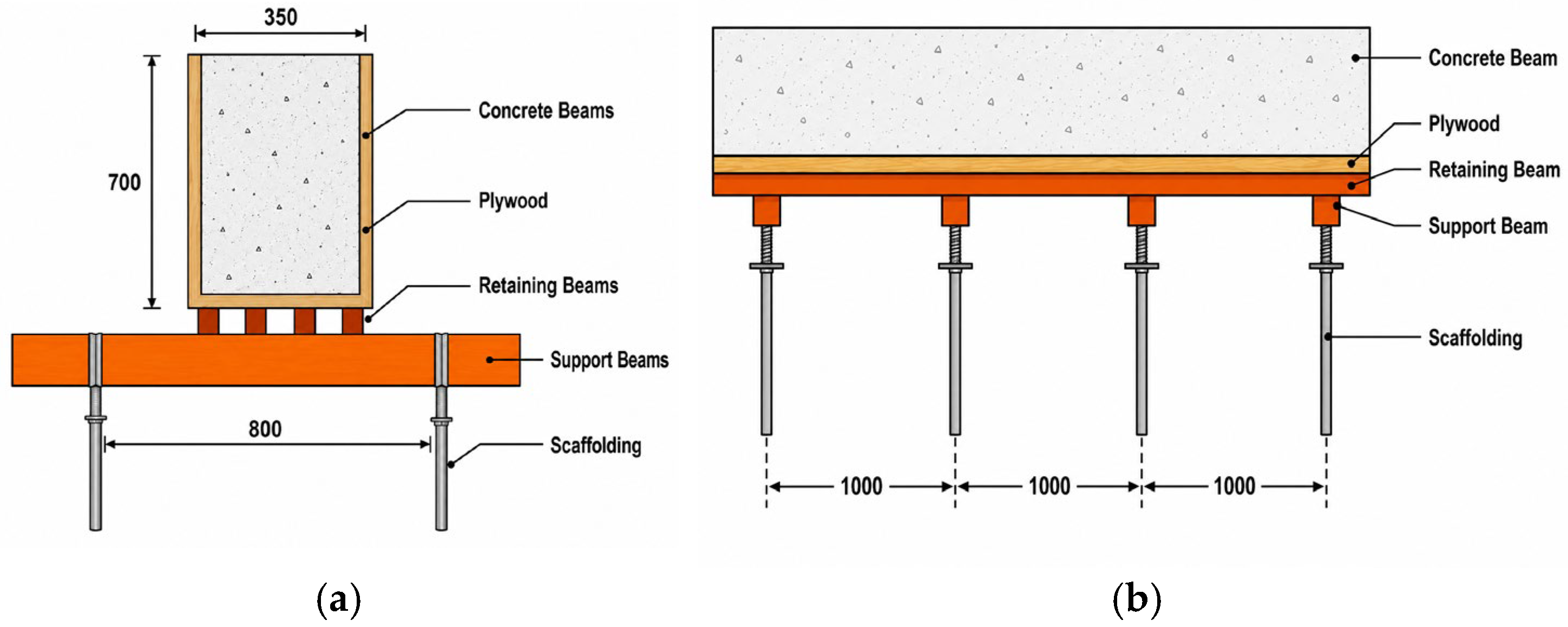
The following technical data on materials and construction drawings use millimeters as the unit of measurement, as shown in Figure 4 below.
Figure 4.
(a) The top image shows a detailed cross-section of the formwork structure, while the bottom image (b) shows a detailed side view. (Source: researcher).
3.1. Analysis of Plywood Formwork
The loads acting on the plywood are its own weight, the weight of wet concrete, casting equipment, and workers.
The weight of reinforced concrete according to SNI 2847-2013 is 2400 kg/m3, therefore [18]:
Concrete Beam Dimensions
b = 0.35 m
h = 0.70 m
h = 0.70 m
In this project, pine wood is used for the plywood formwork with the following material data and plywood dimensions.
Corrected flexural strength
Corrected shear strength
Corrected tensile strength parallel to the grain
Corrected fiber-parallel compressive strength
Corrected uniform flexural modulus of elasticity
Formwork width reviewed
Formwork thickness
Formwork specific gravity
Formwork weight
Cross-sectional area of formwork beam
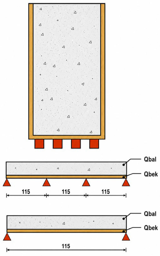
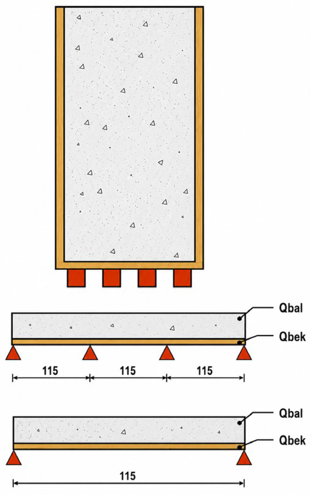
Then, from the above data, the reaction and moment are calculated based on the structural model in Figure 5. With a time factor (λ) = 0.8.
Figure 5.
Floor Structural model (Source: researcher).
From the plywood data above, we can see the flexural, shear, and deflection controls that occur on plywood boards:
Flexural control:
Slider control:
Deflection control:
where the deflection according to SNI 7973-2013 is ℓ/300 [19].
Because δ is smaller than ℓ/300, the plywood is safe, so the contractor provides additional beams under the plywood to increase strength.
3.2. Analysis of Retaining Beams and Support Beams
In formwork construction, retaining beams and support beams are used as shown in Figure 4. The retaining beams and support beams are made of meranti wood. The data on meranti wood is as follows [20].
Specific gravity
Corrected uniform bending modulus of elasticity
Bending strength
Shear strength
Tensile strength parallel to grain
Compressive strength parallel to the grain
Corrected flexural strength
Corrected shear strength
Corrected tensile strength parallel to the grain
Corrected fiber parallel compressive strength
From the data above, an analysis of the retaining beam can be performed, in accordance with its profile data in the form of flexural, shear, and deflection control.
The reactions and moments that occur in the retaining beam are shown in Figure 6 below.
Figure 6.
Retaining beams structural model (Source: researcher).
Weight of retaining beam.
Height (h) = 70 mm = 0.07 m
Width (b) = 50 mm = 0.05 m
Weight of retaining beam
Dead load weight
Total load
After obtaining the ultimate load, the strength and safety of the formwork support beams can be checked.
Flexural check:
Flexural control: if the ultimate moment load (Mu) is smaller than the moment capacity of the beam cross-section, then the construction is safe with the following calculation.
Shear control:
Shear control: if the ultimate shear load (Vu) is less than the shear cross-section capacity of the beam, then the beam construction is safe with the following calculation
Deflection control:
Deflection control: if the deflection that occurs (δ) is smaller than the allowable deflection (ℓ/300) for a two-span beam, then the beam construction is safe against deflection with the following calculation:
With details
So, with the existing values, the above equation yields the following values:
Meanwhile, the deflection of the permit is (ℓ/300) = 3.333 mm.
Since δ is smaller than ℓ/300, the formwork beam is safe from deflection.
After that, the support beam was checked. In accordance with the profile data, flexural, shear, and deflection checks were carried out in the same way as for the retaining beam.
The loads acting on the support beams include the load of fresh concrete beams, the load of plywood boards, and the load of retaining beams.
Weight of support beam
Height (h) = 120 mm = 0.12 m
Width (b) = 60 mm = 0.06 m
Support beam weight
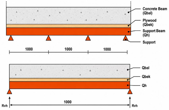
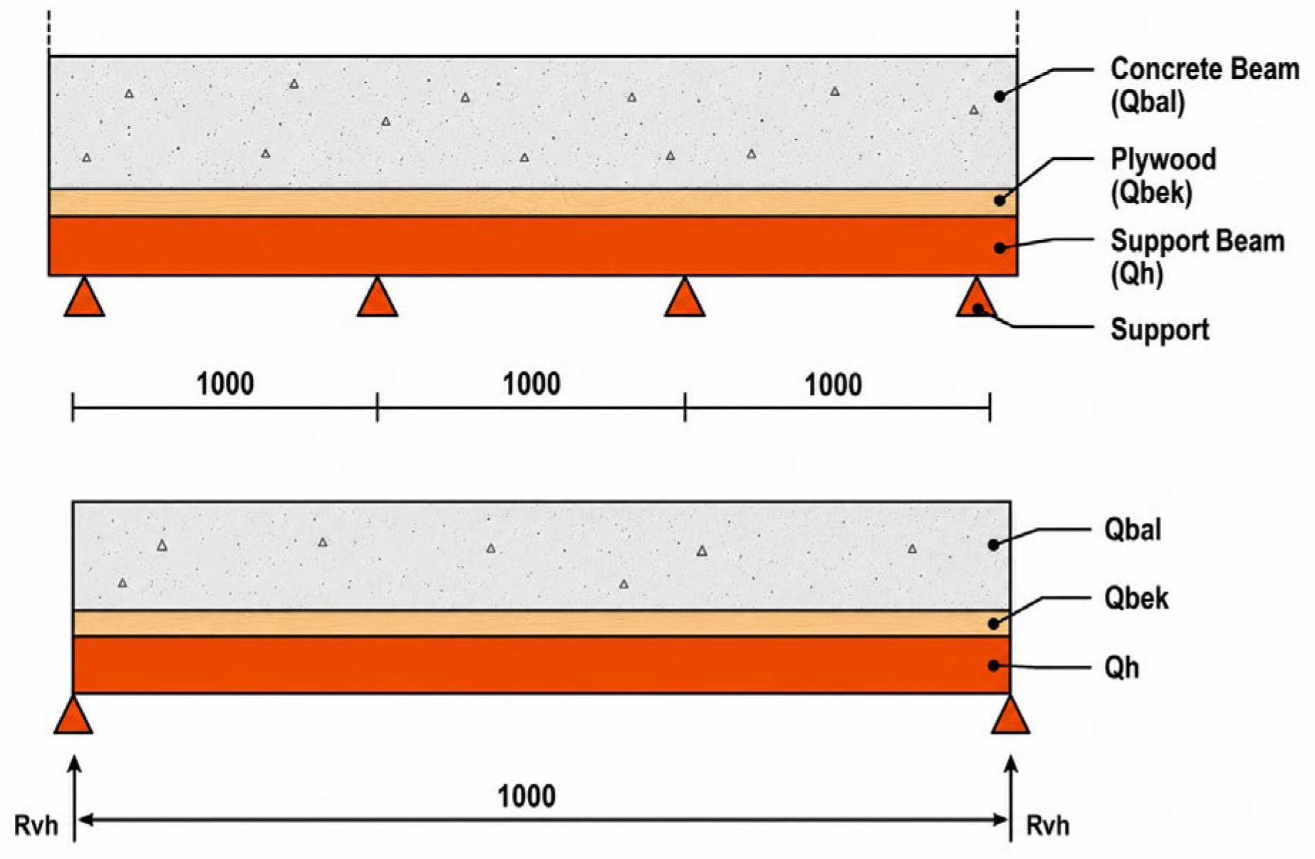
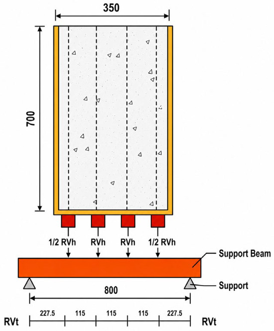
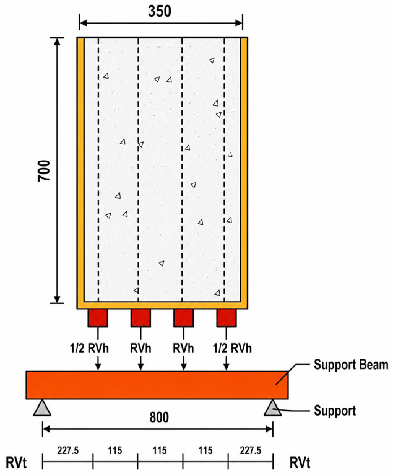
Then, the reaction force (Rv) and maximum moment (M) occurring on the support beam are calculated based on the structural model in Figure 7.
Figure 7.
Support beams model (Source: researcher).
After calculating the moments Mc, Md, and Me, the largest value is taken for further calculation.
Next, after calculating Me, Mtotal is found using the following method.
A difficult moment
Use the load factor with the equation
Flexural control:
Shear control:
Deflection control:
(because the results of small deflections are ignored)
Since δ is smaller than ℓ/300, the formwork beams are safe against deflection.
Construction safety factor calculation is done as follows.
Flexural control on plywood boards:
Based on the criteria in Table 1, this board construction is safe and inefficient. For other controls and constructions, calculations can be made according to the example above. The results of the above construction calculations can be summarized in Table 2 below.
Table 2.
Results of formwork structure control.
Table 2 above shows that the plywood boards used in the flexural control, shear control, and deflection control yielded results of EV > 4. According to the criteria in Table 1, the use of plywood boards is safe but inefficient, resulting in material waste, especially in terms of the 5/7 casing wood, of which four pieces were installed. This condition can be optimized by reducing the number of rafters to 3 pieces. Another alternative is to use 10 mm thick plywood. Furthermore, on the flexural and shear control beams, EV = 1.26 and 2.20 were obtained, which are in accordance with safe and efficient criteria. Meanwhile, on the deflection control, EV = 29.24 was obtained, which is considered inefficient. Then, for the support beams controlling bending and shear, EV = 2.43 and 3.01 are obtained, which meet the safety and efficiency criteria. Meanwhile, for the deflection control, EV = 127 is obtained, which is inefficient.
4. Conclusions
From the analysis results, it was found that the load flow was from the weight of the concrete to the plywood board, to the support beams, to the bearing beams, and then to the scaffolding and finally to the foundation.
In general, the construction of the plywood boards, flexural control, shear, and deflection are safe but inefficient due to the plywood being too thick and the distance between the support beams being too close. The support beams and bearing beams are safe in terms of flexural control, shear, and deflection, but inefficient in terms of deflection control.
The efficient use of formwork timber is obtained from the planned flexural strength and shear strength. Furthermore, for implementation, the plan is made in the form of shop drawings.
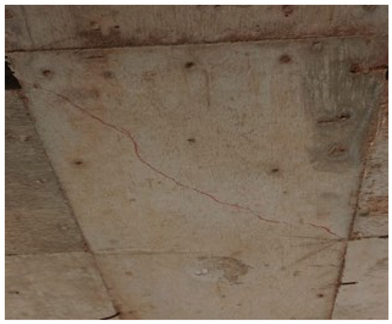
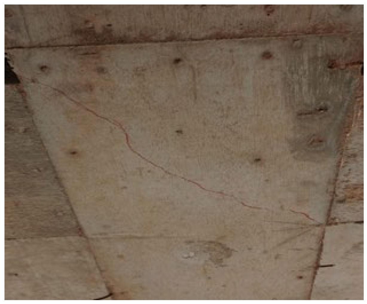
The formwork construction can be used properly, but in reality, contractors remove the formwork structure too quickly, even though the concrete is not yet ready to bear the load, causing cracks in the lower part of the concrete beams. Cracks in the beams occur due to tensile forces on the lower part of the beams, as shown in Figure 8.
Figure 8.
Cracks in beams (Source: researcher).
During project implementation, technical data related to the implementation of wooden formwork must be available and supported by strength analysis.
Author Contributions
Supervision, Validation, Conceptualization, and Methodology, M.N.A.; Data curation and Formal analysis, V.; Writing—original draft, M.F.F.; Writing—review & editing, Formal analysis and Validation, A.H.; Project administration, Investigation, and Methodology, I.P. All authors have read and agreed to the published version of the manuscript.
Funding
This research received no external funding.
Institutional Review Board Statement
Not applicable.
Informed Consent Statement
Not applicable.
Data Availability Statement
The data presented in this study are available on request from the corresponding author.
Acknowledgments
The authors would like to express their sincere gratitude to the Faculty of Science and Technology, Universitas Muhammadiyah Kalimantan Timur, for the continuous support, facilities, and guidance provided throughout this research.
Conflicts of Interest
The author declares no conflicts of interest.
References
- Asnan, M.N.; Khoirulliyah, A.A.; Noor, R.; Vebrian, V. Assesing compressive strength variations of galam wood in construction: A study of different sections and ratios. Tek. J. Sains Teknol. 2023, 19, 136–144. [Google Scholar] [CrossRef] [Scilit]
- Pitaloka, H.I. Analisis Kekuatan Dan Metode Bekisting Pada Tower Intake Blok 8 Bendungan Gondang Karanganyar PT. Waskita Karya (Persero) Tbk. Doctoral Dissertation, Universitas Gajah Mada, Yogyakarta, Indonesia, 2017. [Google Scholar]
- Wang, L.; Yang, Y.; Yao, L.; Ma, G. Interfacial bonding properties of 3D printed permanent formwork with the post-casted concrete. Cem. Concr. Compos. 2022, 128, 104457. [Google Scholar] [CrossRef] [Scilit]
- Li, W.; Lin, X.; Bao, D.W.; Xie, Y.M. A review of formwork systems for modern concrete construction. Structures 2022, 38, 52–63. [Google Scholar] [CrossRef] [Scilit]
- Perwitasari, D.; Susanti, J.E.; Mashur, A.R. Analisa Perbandingan Metode, Biaya Dan Waktu Penggunaan Bekisting Aluminium Dengan Bekisting Konvensional, Semi Konvensional Dan Sistem (PERI); Research Repository—ITERA: South Lampung, Indonesia, 2012; pp. 1–12. [Google Scholar]
- Shrivastava, A.; Chourasia, D.; Saxena, S. Planning of formwork materials. Mater. Today Proc. 2021, 47, 7060–7063. [Google Scholar] [CrossRef] [Scilit]
- Devi, K.; Yadav, T. Cost Comparison of Different Types of Formworks. J. Build. Mater. Sci. 2023, 5, 32–38. [Google Scholar] [CrossRef] [Scilit]
- Wahyudi, I.; Sitanggang, J.J. Kualitas Kayu Meranti Merah (Shorea leprosula Miq.) Hasil Budi Daya. J. Ilmu Pertan. Indones. (JIPI) 2016, 21, 140–145. [Google Scholar]
- Agussalim, A. Peningkatan Mutu Kayu Pinus Yang Terserang Bluestain. J. Perenn. 2018, 14, 28–31. [Google Scholar] [CrossRef] [Scilit]
- Christina, W.Y.; Djakfar, L.; Thoyib, A. Pengaruh Budaya Keselamatan Dan Kesehatan Kerja (K3) Terhadap Kinerja Proyek Konstruksi. J. Rekayasa Sipil 2012, 6, 83–95. [Google Scholar]
- Asnan, M.N.; Vebrian Sunaryo, S.; Ramadhan, R.F. Analisis Hubungan Antara Tinggi dan Diameter Benda Uji Kayu Galam Terhadap Kuat Tekan. In Proceedings of the Konferensi Nasional Teknik Sipil (KonTekS) Ke-16, Bali, Indonesia, 27–28 October 2022; Volume 16, pp. 407–414. [Google Scholar]
- Asnan, M.N.; Arha, A.A.; Yatnikasari, S.; Agustina, F.; Vebrian. The analysis study of strength on concrete formwork wood construction. Ann. Chim.—Sci. Matér. 2023, 47, 17–23. [Google Scholar] [CrossRef] [Scilit]
- Arman, U.D.; Melasari, J.; Suwanda, A.R. Identifikasi Penyebab Kecelakaan Kerja Konstruksi Menggunakan Accident Root Cause Tracing Model (ARCTM) dan Fault Tree Analysis (FTA). Cantilever J. Penelit. Kaji. Bid. Tek. Sipil 2022, 11, 17–28. [Google Scholar] [CrossRef] [Scilit]
- Asnan, M.N.; Vebrian, V. Study of the effect of the bark on the compression strength of galam wood (Melaleuca Cajaputi). AIP Conf. Proc. 2024, 2927, 030013. [Google Scholar] [CrossRef] [Scilit]
- Arifin, N.F.R.; Nahdiyah, N.E.; Efrein, C.; Hidayat, M.F.; Wardhana, R.D.; Fakhruddin, F. The Utilization of Geopolymer Mortar as Permanent Formwork in Reinforced Concrete Beam. Mater. Sci. Forum 2023, 1091, 143–149. [Google Scholar] [CrossRef] [Scilit]
- Zarmihan, R.P.; Pratiwi, V.; Krisnadi, S. Studi Perbandingan Kekuatan Profil IWF, Hexagonal Beam dan Octagonal Beam dengan Perhitungan Manual dan Metode Elemen Hingga. Cantilever J. Penelit. Kaji. Bid. Tek. Sipil 2022, 11, 129–140. [Google Scholar] [CrossRef] [Scilit]
- Terzioglu, T.; Polat, G.; Turkoglu, H. Analysis of formwork system selection criteria for building construction projects: A comparative study. Buildings 2021, 11, 618. [Google Scholar] [CrossRef] [Scilit]
- SNI 2847-2013; Persyaratan Beton Struktural Untuk Bangunan Gedung. Badan Standarisasi Nasional: Jakarta, Indonesia, 2013.
- SNI 7973-2013; Spesifiksai Desain Untuk Konstruksi Kayu. Badan Standarisasi Nasional: Jakarta, Indonesia, 2013.
- NI-5 PKKI 1961; Peraturan Konstruksi Kayu Indonesia. Departemen Pekerjaan Umum Direktorat Jenderal Ciptakarya Direktorat Penyelidikan Masalah Bangunan: Bandung, Indonesia, 1961.

Disclaimer/Publisher’s Note: The statements, opinions and data contained in all publications are solely those of the individual author(s) and contributor(s) and not of MDPI and/or the editor(s). MDPI and/or the editor(s) disclaim responsibility for any injury to people or property resulting from any ideas, methods, instructions or products referred to in the content. |
© 2026 by the authors. Licensee MDPI, Basel, Switzerland. This article is an open access article distributed under the terms and conditions of the Creative Commons Attribution (CC BY) license.