


Abstract
Europe’s global liquid hydrogen production share remains limited at 7%, while research institutions face an inadequate supply chain for laboratory-scale procurement. The Department of Energy at Politecnico di Milano addresses this gap through the procurement of Italy’s first laboratory-scale LH2 liquefaction system, designed with 70 L/day capacity, a 200 L ATEX-classified storage tank, and a 50 L mobile transport tank for investigations into heat transfer, cryogenic valve and sensor testing, superconducting electronics, and material compatibility. The absence of Italian standards and limited European precedents necessitated a comprehensive review of relevant European safety projects and industrial guidelines. Regulatory compliance is ongoing under ATEX directives, with safety consultants defining critical parameters via leakage simulations. The project requires around three years from conception to commissioning; this paper aims to accelerate similar implementations by sharing the experience at Politecnico di Milano for future laboratory-scale facilities. Systematic coordination among engineering design, safety consultation, and regulatory authorities remains essential for viable LH2 infrastructure implementation.
1. Introduction
Hydrogen has emerged as a pivotal energy vector in transitioning towards decarbonized energy systems, with its role expanding within climate mitigation frameworks aligned with net-zero emissions. Among the pure forms of hydrogen storage, liquid hydrogen (LH2) offers significantly enhanced volumetric energy density—approximately 80% higher than that of gaseous hydrogen stored at ambient temperature and 70 MPa [1]. This enables LH2 to be particularly suited for decarbonizing energy-intensive and weight-sensitive mobile sectors, including trucks, trains, ships, airplanes, and drones. Global liquid hydrogen capacity, however, remains constrained, currently estimated at 380 tons per day. Table 1 shows Europe’s liquefaction capacity, which accounts for merely 7% of the global total [2]. This capacity imbalance creates severe procurement challenges across Europe, particularly for research institutions, limiting the experimental validation essential for aerospace and clean energy advancements. Consequently, LH2 technology development remains constrained, relying heavily on mid-twentieth-century programs focused on space applications.
Table 1.
European overview of industrial-scale hydrogen liquefaction plants in operation [2].
Contemporary research appears dominated by modeling-based studies, with sparse experimental campaigns conducted at very few dedicated facilities across Europe. This is justified by the fact that procurement of laboratory-scale quantities of LH2 remains economically inefficient through existing channels; conventional tanker deliveries—typically ranging from 2500 to 3500 kg—prove operationally and financially prohibitive for research institutions requiring only kilogram quantities [3]. Table 2 provides an outlook of the existing European LH2 research landscape.
Table 2.
European laboratory-scale hydrogen liquefaction facilities known to the authors.
This paper aims to address this gap by sharing the experience of acquiring a lab-scale hydrogen liquefaction system at Politecnico di Milano—Italy’s first LH2 system designed to support the development of clean energy technologies. This work is in synergy with Politecnico’s role in the European project EFACA—Environmentally Friendly Aviation for All Classes of Aircraft—a Horizon Europe initiative funded by the European Commission, with the goal of decarbonizing the aviation sector by 2050 [9]. The system is co-funded by the Hydrogen Joint Research Partnership (JRP), a strategic platform created by Fondazione Politecnico di Milano, tailored for all companies willing to support Italy’s research and development of hydrogen products and services [10].
2. Hydrogen Liquefaction at Politecnico di Milano
The hydrogen liquefaction system will be employed to conduct multifaceted experimental research. The facility enables investigation of heat transfer at cryogenic temperatures, where liquid hydrogen serves simultaneously as refrigerant and test medium. Material-hydrogen interactions will be studied under extreme conditions—testing metals and polymers at −253 °C to assess compatibility for cryogenic storage and transfer. The system will potentially support the testing of superconducting motors and power electronics through direct cooling of high-temperature superconducting magnets.
Preliminary Design of the System and Installation Site
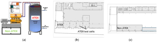
The design methodology was aided by an Italian gas company from Hydrogen JRP, combining site inspections and technical consultations to align the system with building constraints. Initial site visits examined the BL25A building at the Department of Energy—located at Via Lambruschini 4A, Milan—and identified feasible locations. After receiving several quotations from potential suppliers, a targeted liquefaction capacity of 70 L/day of LH2 (equivalent to 600 MJ/day) has been identified. As shown in Figure 1a, the system is set to be architecturally divided into two distinct operational zones for safety compliance: an ATmosphères EXplosibles (ATEX) part and a non-ATEX part.
Figure 1.
(a) SPC-1T cryocooler, vacuum-jacketed helium line (3 m), and integrated heat exchanger targeting 70 L/day of LH2; (b) Ground floor ATEX Zone: 200 L fixed tank, and 50 L mobile tank. Hydrogen inlet from electrolyzer at 30 bar progressively cooled and liquefied; (c) First floor non-ATEX zone: helium cryocooler, glycol-water circulation, instrumentation, and control electronics.
The ATEX part comprises the fixed storage tank (200 L capacity), which embeds the hydrogen-helium heat exchanger. This part is installed within the ATEX-classified cylinder room located at ground level in the BL25A building (see Figure 1b)—a potentially explosive atmosphere environment, where hydrogen release and ignitable vapor-air mixtures may occur. All components within this space—sensors, valves, and electrical equipment—must carry ATEX certification, ensuring no ignition in the presence of hydrogen. The fixed tank operates from 1 to 3.5 bar, providing full refill capacity in less than three days at nominal load, storing approximately 1700 MJ of energy. Hydrogen feed from the on-site electrolyzer enters at around 30 bar and is progressively cooled through the helium-based heat exchanger, liquefied, and collected within the fixed tank.
The non-ATEX part houses the helium cryocooler and associated control systems, intentionally positioned indoors on the first floor of the BL25A building (see Figure 1c) to isolate active machinery from hydrogen presence. The cryocooler—based on the Stirling cycle—operates at 15 kW electrical power and requires cooling glycol-water circulation (1200 L/h at 15 °C, ∆P 2.5 bar). This separation eliminates the possibility of mechanical failure or any event triggering hydrogen ignition within the confined ATEX zone.
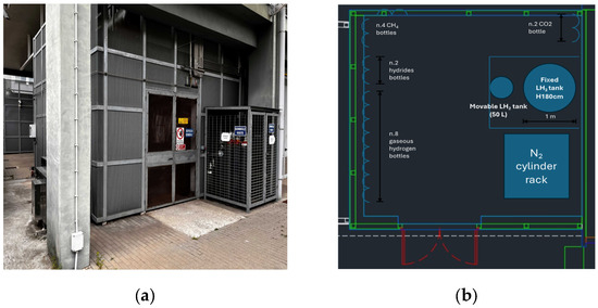
A vacuum-jacketed helium transfer line (3 m nominal length) connects the non-ATEX to the ATEX part, conveying cold helium gas through a loop to the liquefying heat exchanger integrated in the fixed tank. The line design minimizes parasitic heat loss, ensuring cryogenic efficiency. Liquid hydrogen is transferred from the fixed tank to the movable 50 L tank via bayonet quick-disconnect couplings with hand valves, allowing rapid, secure connection during filling operations. The movable tank, when parked in proximity to the fixed tank within the cylinder room, rests on a designated pad; upon filling, it is transported via an external pathway to the two ATEX test cells (see Figure 1b), ensuring hydrogen never enters the building interior. Figure 2a shows the exterior of the ATEX zone, i.e., the cylinder room, and Figure 2b shows the interior of the ATEX zone.
Figure 2.
(a) External entrance: Controlled-access portal with restricted entry to authorized personnel. Passive ventilation architecture comprises a grated door (2 m × 3 m, 70% porosity) and lateral windows (2.5 m × 0.5 m, 70% porosity) for continuous background dilution; (b) Internal layout: 200 L fixed tanks sited on an insulated pad with a drip basin, and a designated pad for the 50 L mobile tank. A ceiling-mounted hydrogen sensor with a 1% vol. threshold, equal to 25% of 4% Lower Flammability Limit (LFL) [11], activates the forced extraction hood (50 cm × 50 cm) and alarms.
3. Regulatory Framework Basis for Experimental Safety Protocols
Establishing a university-based liquid hydrogen infrastructure requires a rigorous safety validation framework prior to active experimentation. As the facility is currently in the construction phase, the primary research focus is to define the operational protocols derived from a synthesis of guidelines and pre-normatives. This analysis is particularly critical given the absence of specific Italian safety standards regulating liquid hydrogen systems. While the current absence of on-site liquid hydrogen precludes the presentation of experimental data, this regulatory analysis establishes the starting point for future testing on heat transfer, materials, and superconducting electronics previously cited.
3.1. European Projects
Prenormative Research for Safe Use of Liquid Hydrogen (Horizon 2020, grant 779613, 2018–2021), known as PRESLHY, conducted experimental and theoretical investigation into liquid hydrogen safety phenomena, including release behavior, cryogenic dispersion, and combustion characteristics. The project validated computational models for hazard assessment and produced engineering correlations predicting minimum ignition energy, flame characteristics, and thermal radiation distances from hydrogen combustion [12].
HyResponder (2020–2023, Clean Hydrogen JU, grant 875089) developed—for the first time in European history—four stratified training programs for hydrogen emergency responders: firefighter, crew commander, incident commander, specialist adviser. Practical scenario-based training addressed liquid hydrogen incidents: liquid spreading, cryogenic cloud dynamics, tank fires, trailer overturn scenarios [13].
3.2. Industrial Guidelines
European Industrial Gases Association (EIGA) Doc 06/19 provides comprehensive guidelines for the safe storage, handling, and distribution of liquid hydrogen, defining tank design, pressure relief systems, vent stack requirements, hazardous area classification, and separation distances. The document is grounded in experimental data and serves as a core reference for regulatory compliance in hydrogen installations [14].
Asian Industrial Gases Association (AIGA) Doc 129/25, adopted from the Compressed Gas Association standard (CGA) G-6, characterizes physiological hazards from cryogenic exposure: frostbite, asphyxiation, and hypothermia. The standard specifies insulation design, material compatibility, boiling rates, and cooling water requirements [15].
EIGA Doc 250/24, originally published by the CGA H-7, establishes mandatory commissioning, purging, maintenance, and decommissioning procedures for bulk hydrogen systems. The document addresses hazard analysis, nitrogen displacement purging to low oxygen concentrations, grounding resistance, and personnel training [16].
4. Project Outlook: Status and Next Steps
In this chapter, the project spanning from Q1 2024 to Q3 2026 is outlined, referring to the actual status at mid-Q4 2025. The hydrogen liquefaction system involves parallel procurement and safety authorization activities. In the final section of this chapter, the project delays and mitigation strategies adopted are presented.
4.1. Design, Procurement, and Commissioning Status
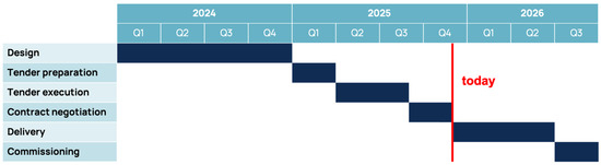
The design, procurement, and commissioning process consists of structured phases, represented in the Gantt chart in Figure 3. The first task was the design phase—assessed in Chapter 2—carried out in 2024: during this time, the installation site inside building BL25A was identified along with all technical requirements—capacity, ATEX/non-ATEX zones, transfer logistics, and integration with the existing green hydrogen supply.
Figure 3.
Gantt chart of the design, procurement, and commissioning process of the system.
Tender preparation began in Q1 2025 and relied on a formal structure compliant with public procurement regulations. In fact, the tender document outlined specific, quantifiable technical requirements. The technical evaluation formed 70% of the overall score, while the economic offer covered the remaining 30%. Only proposals compliant with every mandatory criterion underwent price evaluation. These included:
- Minimum continuous liquefaction rate of at least 5 kg/day,
- Fixed cryogenic storage vessel not less than 200 L,
- Full ATEX certification for all equipment installed in the ATEX zone,
- Delivery and installation timeline not exceeding 12 months from contract signature,
- Training of a minimum of five technical staff, with at least 8 h of classroom,
- Warranty covering two years of operation, extendable by annual agreement,
- Maintenance service guaranteed within 72 h of any reported issue,
- Comprehensive documentation and Conformité Européenne (CE) markings.
At last, the acceptance test will require the system to demonstrate achievement of 100% of the specified 5 kg/day liquefaction rate over two consecutive operating days, as well as safe venting, emergency stop response, and hydrogen detection.
Tender execution began in Q2 2025—with the launch of a public European call—and concluded in Q3 2025 with the final evaluation of the bids performed by a nominated commission. The tender has been awarded to the supplier that scored the highest according to the evaluation grid of the tender document. The successful supplier was notified by Q3 2025, and contract discussions are now (mid-Q4 2025) underway between them and the university legal office. These formalities define responsibilities for transport, commissioning, training, warranty, and support, along with anti-money laundering clauses. Capital expenditure is approximately allocated as follows: liquefaction system 50%; storage tanks 20%; safety and site preparation 20%; installation and commissioning 10%.
System delivery is scheduled for Q3 2026, with the main equipment arrival and on-site commissioning. The same Italian gas company that contributed expertise during the design phase will participate directly in the installation and acceptance testing.
4.2. Safety Authorization Status
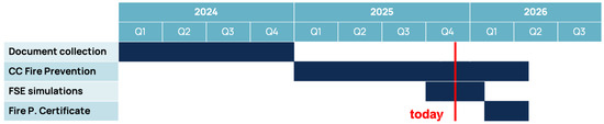
Safety authorization follows a structured timeline (see Figure 4) coordinated with the procurement activities. The process began in 2024 with the collection of existing safety guidelines—presented in Chapter 3—requested by the university safety office. This foundational documentation served to frame safety requirements before formal authorization.
Figure 4.
Gantt chart of the safety authorization process of the system.
In Q1 2025, the safety office initiated the Commencement Certificate (CC) for the Fire Prevention procedure to update all safety measures applicable to the BL25A cylinder room. This formal notification to Italian fire authorities signals institutional intent to operate the hydrogen liquefaction system and triggers regulatory review.
At the beginning of Q4 2025, external safety consultants were engaged to conduct Fire Safety Engineering (FSE) analysis. This phase involves Computational Fluid Dynamics (CFD) simulations focused on the cylinder room. The simulations address external consultants’ primary concern: unplanned liquid hydrogen leakage. Some boundary conditions were required for simulation modeling, such as the LH2 tank locations, movement routes, and operating pressures. The external consultants suggested simulating liquid hydrogen dispersion directly from the fixed tank under a defined worst-case condition: leak through a 1 mm diameter hole, driven by a pressure differential of 1 bar (2 bar internal minus 1 bar ambient), with an outflow rate estimated at 2.5 g/s.
Preliminary CFD simulations validated the cylinder room design (5.5 m × 5.5 m), confirming that a 50 cm × 50 cm forced extraction hood (1.52 m3/s) is critical. Without ventilation, flammable concentrations exceeding the 4% LFL form within a 1.5 m radius. However, forced ventilation triggered at 1% concentration (25% LFL) via a ceiling-mounted detector effectively contains the cloud, limiting the flammable mass to 50 g and maintaining safety beyond 2 m from the source. Explosion overpressure simulations yield a maximum overpressure of <25 mbar. This remains well below the 30 mbar threshold for human injury, confirming that the present walls (20 cm reinforced concrete) require no blast relief panels. The final ATEX classification for the cylinder room is “improbable/short-duration explosive atmosphere”. Lastly, during filling operations and the movement of the 50 L mobile tank, forced ventilation must be activated to maintain continuous hydrogen dilution, persisting for at least 15 min post-operation.
Final regulatory approval via the Fire Prevention Certificate is scheduled for Q1–Q2 2026, enabling system commissioning in alignment with procurement completion.
4.3. Critical Analysis of Project Delays and Mitigation Strategies
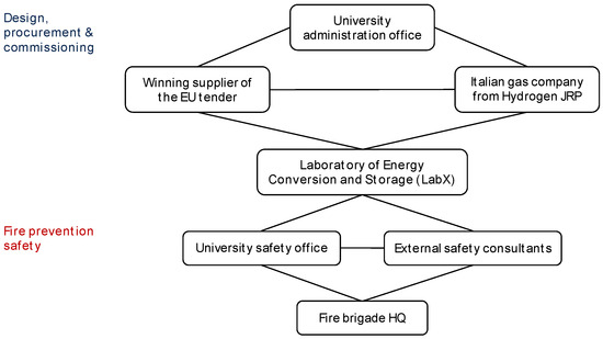
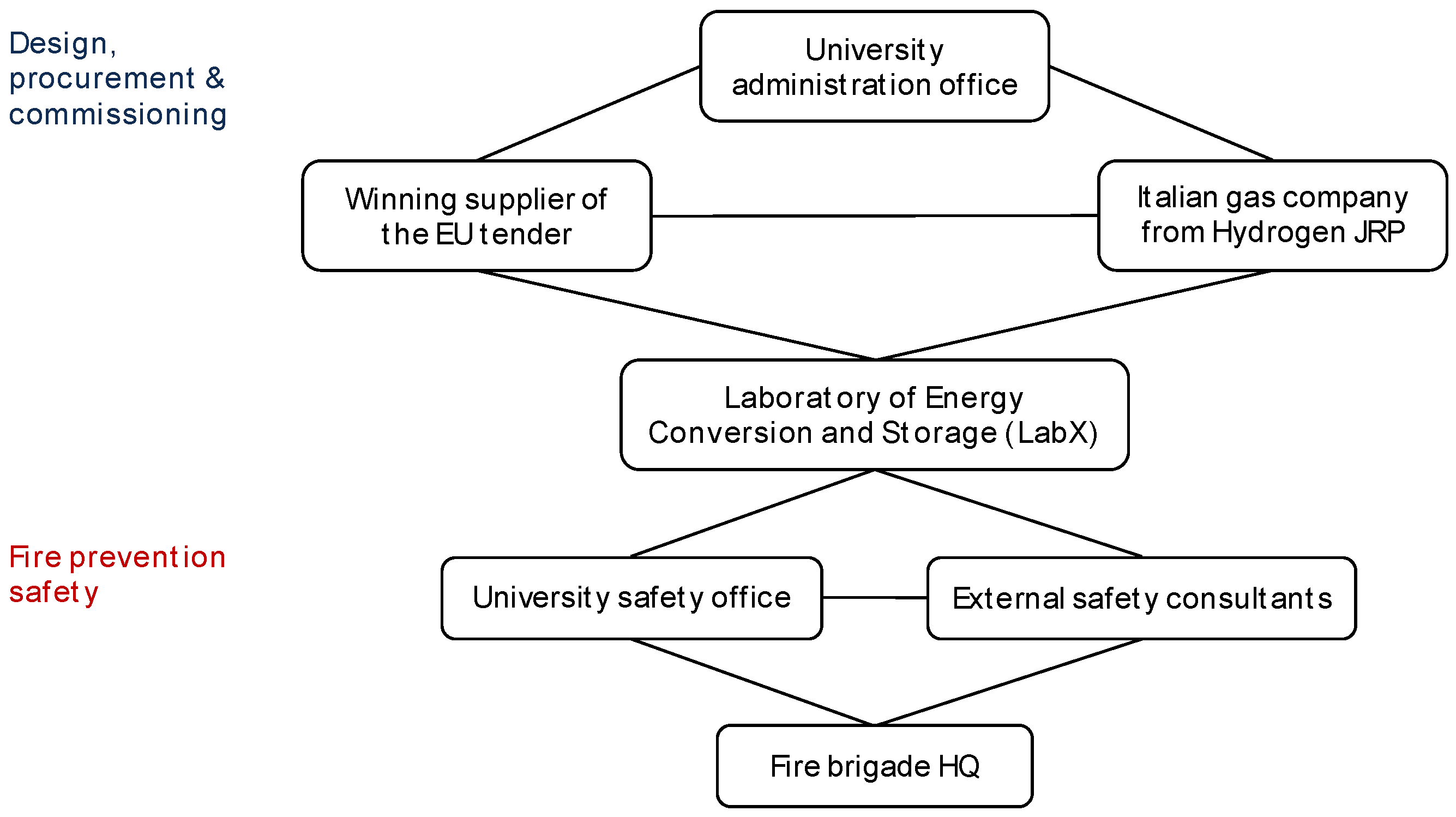
Implementing a first-of-a-kind LH2 lab facility introduces unique management challenges beyond standard engineering. While Figure 3 and Figure 4 outline the plan, actual execution revealed significant friction points. Delays primarily stemmed from regulatory inertia, as the lack of LH2 standards required an iterative approval process that added 4–6 months. Procurement was similarly complicated by public tender rules conflicting with the nature of the cryogenic equipment, necessitating extended market consultation. Stakeholder interdependence was also critical. As shown in the stakeholder map (Figure 5), sequential validation across administrative, technical, and safety bodies meant that bottlenecks in one node stalled the entire network. To mitigate this, the project adopted a parallel execution model. Safety reviews began pre-tender using “worst-case” design envelopes, decoupling regulatory approval from supplier negotiations. Additionally, our research group—Laboratory of Energy Conversion and Storage, LabX—served as the coordinator, bridging the gap between administrative frameworks and project realities.
Figure 5.
Stakeholder map: design, procurement, and commissioning (in blue) and fire prevention safety (in red)—LabX represents the central linking agent between the two workstreams.
5. Conclusions
The following conclusions have been drawn from this work:
- Europe’s liquefaction capacity accounts for merely 7% of the global total. Laboratory-scale procurement remains unfeasible through industrial channels, where minimum delivery volumes (2500 kg) vastly exceed academic research requirements.
- The system at Politecnico di Milano represents Italy’s first laboratory-scale LH2 infrastructure (70 L/day capacity). The design separates the helium cryocooler (non-ATEX zone) from the hydrogen liquefaction and storage (ATEX zone), which features a 200 L fixed tank and a 50 L mobile tank for internal transfer.
- The absence of specific Italian safety standards for research-scale LH2 systems necessitated a compliance framework derived from European pre-normative projects (PRESLHY, HyResponder) and industrial guidelines (EIGA, AIGA).
- A European public tender was successfully executed in Q3 2025, mandating strict technical criteria, full ATEX compliance, and extended maintenance warranties.
- Preliminary Fire Safety Engineering (FSE) analysis (Q4 2025) validated the cylinder room design. CFD simulations confirmed that active mechanical extraction effectively manages the worst-case LH2 leakage scenario (2.5 g/s), maintaining safety margins without requiring structural blast relief panels.
- The project highlighted significant friction from regulatory inertia and stakeholder interdependence. Success relied on adopting a parallel execution model—decoupling safety authorization from procurement—and establishing a centralized technical coordination role to bridge administrative and engineering requirements.
Author Contributions
Conceptualization, D.T., A.B. and G.V.; methodology, D.T. and G.V.; writing—original draft preparation, D.T.; writing—review and editing, D.T. and G.V.; project administration, G.V.; funding acquisition, G.V. All authors have read and agreed to the published version of the manuscript.
Funding
This work is framed in the Environmentally Friendly Aviation for All Classes of Aircraft (EFACA) project. This project is funded by the European Union Horizon Europe research and innovation program (HORIZON-CL5-2021-D5-01-05) under grant agreement no.101056866.
Data Availability Statement
No new data were created or analyzed in this study. Data sharing is not applicable to this article.
Conflicts of Interest
The authors declare no conflicts of interest.
References
- National Institute of Standards and Technology (NIST). Thermophysical Properties of Fluid Systems. Available online: https://webbook.nist.gov/chemistry/fluid/ (accessed on 17 November 2025).
- Zhang, T.; Uratani, J.; Huang, Y.; Xu, L.; Griffiths, S.; Ding, Y. Hydrogen Liquefaction and Storage: Recent Progress and Perspectives. Renew. Sustain. Energy Rev. 2023, 176, 113204. [Google Scholar] [CrossRef] [Scilit]
- Edwards, H.; Clarke, H.; Cuss, L. Aerospace Technology Institute: Cryogenic Hydrogen Future Test Infrastructure and Supply Landscape. Available online: https://www.ati.org.uk/publications/ (accessed on 18 November 2025).
- TU Dresden: Schaufler Chair of Refrigeration, Cryogenics and Compressor Technology. Available online: https://tu-dresden.de/ing/maschinenwesen/iet/kkt?set_language=en (accessed on 4 February 2026).
- Karlsruhe Institute of Technology: Hydrogen Integration Platform (HIP). Available online: https://www.elab.kit.edu/english/hip.php (accessed on 4 February 2026).
- TU Delft Reactor Institute. Available online: https://www.tudelft.nl/en/faculty-of-applied-sciences/business/facilities/tu-delft-reactor-institute (accessed on 4 February 2026).
- IFE Hynor Hydrogen Technology Center. Available online: https://ife.no/en/laboratory/ife-hynor-hydrogen-technology-center-ife-hynor/ (accessed on 4 February 2026).
- Vijulie, M.; Brad, S.; Lazăr, A.; Vasut, F.; Oubraham, A.; Sirosh, A. Preliminary Tests on a Hydrogen Isotope Separation Cryogenic Facility, from ICSI Rm. Valcea. Prog. Cryog. Isot. Sep. 2019, 22, 5–12. [Google Scholar]
- Environmentally Friendly Aviation for All Classes of Aircraft|EFACA|Project|Fact Sheet|HORIZON. Available online: https://cordis.europa.eu/project/id/101056866 (accessed on 17 November 2025).
- Fondazione Politecnico Di Milano: JRP Hydrogen. Available online: https://www.fondazionepolitecnico.it/en/our-work/jrp/jrp-hydrogen (accessed on 17 November 2025).
- Alekseev, A.; Arndt, T.; Haberstroh, C.; Jordan, T.; Lindackers, D.; Palacios Vera, J.S.; Pundt, A.; Saß, P.; Schulz, C.; Weiss, K.-P.; et al. Hydrogen Liquefaction, Storage, Transport and Application of Liquid Hydrogen. Available online: https://publikationen.bibliothek.kit.edu/1000168281 (accessed on 18 November 2025).
- Verfondern, K.; Cirrone, D.; Molkov, V.; Makarov, D.; Coldrick, S.; Ren, Z.; Wen, J.; Proust, C.; Friedrich, A.; Jordan, T. Prenormative Research for Safe Use of Liquid Hydrogen: Chapter on LH2 in Hydrogen Safety Handbook. Available online: https://preslhy.eu/wp/wp6/chapter-lh2-safety/ (accessed on 18 November 2025).
- Brennan, S.; Brauner, C.; Davis, D.; De Backer, N.; Dyck, A.; García-Hernández, C.; Gaathaug, A.V.; Kupka, P.; Grand-Clement, L.; Havret, E.; et al. European Hydrogen Train the Trainer Framework for Responders: Outcomes of the HyResponder Project. Int. J. Hydrog. Energy 2024, 79, 448–455. [Google Scholar] [CrossRef] [Scilit]
- EIGA Publications: DOC 6/19—Safety in Storage, Handling and Distribution of Liquid Hydrogen. Available online: https://www.eiga.eu/uploads/documents/DOC006.pdf?v=1777298512 (accessed on 18 November 2025).
- AIGA Publications: DOC 129/25—Guideline for Safe Handling of Cryogenic and Refrigerated Liquids. Available online: https://asiaiga.org/uploaded_docs/en_AIGA_129_25_Guide_on_Safe_Handling_of_Cryogenic__Refrigerated_Liquids_Final.pdf (accessed on 18 November 2025).
- EIGA Publications: DOC 250/24—Standard Procedures for Hydrogen Supply Systems. Available online: https://www.eiga.eu/uploads/documents/DOC250.pdf?v=1777298512 (accessed on 18 November 2025).

Disclaimer/Publisher’s Note: The statements, opinions and data contained in all publications are solely those of the individual author(s) and contributor(s) and not of MDPI and/or the editor(s). MDPI and/or the editor(s) disclaim responsibility for any injury to people or property resulting from any ideas, methods, instructions or products referred to in the content. |
© 2026 by the authors. Licensee MDPI, Basel, Switzerland. This article is an open access article distributed under the terms and conditions of the Creative Commons Attribution (CC BY) license.