


Abstract
As origami-inspired solutions become more mature in spacecraft structures and applications, new alternatives are arising for traditional designs, allowing for creative and innovative answers to common problems. In this work, we look into space telescopes, one of the most feasible applications for new tubular solutions, using origami structures to propose the design of a self-retractable baffle. An element needed for mitigating both in-field and out-of-field stray light and helping to improve the image quality of the optical system. This baffle is rethought as a tubular, origami-inspired structure, built over a Kresling origami pattern. This choice can be traced back to the properties such structure has to offer: bi-stability, packaging ratio and controllability. Thus, it is becoming a promising alternative to standard baffles and helping to reduce key factors in spacecraft design, such as weight and complexity of the optomechanical mechanism. To demonstrate its effectiveness in an optical system, the professional software ASAP (Advanced System Analysis Program) is utilised to assess the optical performance of the new baffle design. As a result, we verify the applicability of these patterns and, therefore, the whole structure from an optical point of view, confirming the interest of its application as a telescope baffle. This solution also allows moving and modifying the inclination, shape or size of the baffle, selecting the amount of screening and light incidence into the telescope in a controlled manner depending on the orbit and attitude of interest.
1. Introduction
As the optical design of space telescopes becomes more and more sophisticated, new design problems arise for each of their components, calling for their in-depth analysis, optimisation, and, to reach even further, the search for out-of-the-box solutions. In this work, we will focus on a critical yet simple element, the baffle of such telescopes, and how different structural configurations and designs can carry on the improvement of the whole system in terms of weight, simplicity, and optical performance.
Baffles can be identified as one of the optical protection systems of the telescope, ensuring that the light that reaches the inner optical path of the instrument does not include any stray component, i.e., any light source from non-desired measured objects. This is translated into a physical barrier that controls the incident light directionality and, at the same time, can be used to improve contrast in the inner sensors: by eliminating stray light, baffles improve the contrast of celestial objects, making them appear sharper and more defined.
As a result, their configuration is usually chosen as cylindrical, with inner vanes that both define the structural shape and serve as supports for inner optical elements such as mirrors, lenses or even additional baffles to enhance even more the quality of the measured light. We will refer to these cylindrical baffles as conventional ones because of their wide range of use and application. These conventional geometries, while simple in design, involve some drawbacks that are continuing with the increasing optical requirements of newer telescopes [1], the most critical being their fixed size. As wider and longer baffles are required, their weight, volume and stowing complexity considerably limit the inner space of the launcher’s nacelle.
In this direction, new baffle design proposals appear [2], which present deployable mechanisms that allow the launch size to be reduced. The main drawback of this option lies in the deployment process, which is usually active with a high complexity level. Additionally, a telescopic deployment reduces the available inner deployed volume of the baffle. At the same time, it generates impact charges that will require additional attenuation for the inner elements, even if they are properly distributed in the folded configuration.
Hence, this work presents an alternative deployment mechanism: an origami-inspired baffle that folds and deploys following a tubular shape by rotation in a controlled manner. This solution allows for efficient solving of the volume limitation while avoiding the increase in complexity or reducing the available inner space. Indeed, as a follow-up of previous work [3], we study the optical behaviour of an origami-inspired deployable structure, the proposed baffle, with a final tubular shape and two stable positions: folded and deployed, based on the Kresling Origami Pattern [4,5].
To do so, we will explore the performance of this origami-like shape under the two main requirements of a deployable baffle: the structural size in both folded and deployed positions and its capability as a stray-light barrier. We will therefore compare this solution with the conventional one, following possible stray-light beams at different incident angles throughout both structures by means of a numerical simulation. The telescopic solution has not been considered for the optical analysis, as we will only focus on characterising the optical origami baffle, setting the cylindrical one as the ground floor for its performance. Finally, we will discuss the viability of the proposed origami baffle and its comparison with the cylindrical one, setting the key elements for future in-depth optimisation of the geometry.
2. Materials and Methods
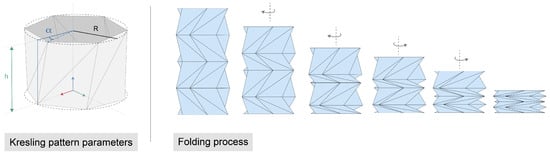
For this optical study, we perform an analysis based on the stray light inside a Kresling origami pattern (see Figure 1).
Figure 1.
Proposed origami representation. Kresling origami parameters (left) and folding process illustration (right).
Through this section, we will introduce both the specifications of the proposed origami deployable baffle, a geometry adapted from previous works [3], focusing on its peculiarities in terms of materials, structural behaviour and, more importantly, volume (or, as we will define, packaging ratio) and deployment process.
Then, we will present the details of the optical analysis that will be performed for both conventional and origami configurations: hypothesis, geometry configuration, and boundary conditions and expected results.
This whole analysis has been done numerically: the geometry was obtained by Python 3.11 scripting optimisation, then imported through Rhino [5] as an input for ASAP NextGen 2021 V2 optical software, the software for the optical stray-light analysis. Nonetheless, the geometry being used as well as their materials are obtained from previous works’ structural [3] and volumetric studies [6], where experimental testing validated these choices.
2.1. Origami Solution
An origami tubular shape is defined by a limited number of geometrical parameters that are constrained by the folding pattern: the origami pattern [7]. Among all available patterns for tubular folding, the Kresling one offers several advantages compared with, for example, the Miura or Yoshimura patterns. These advantages are, from a structural point of view, bi-stability and controlled rotational deployment, advantages that have been explored in [8].
The first one means that our pattern offers a dual stable configuration in a position completely deployed and another one stowed. This property allows the structure to withstand the required loads while it is deployed and stay deployed without any big external load. It is important to mention here that this property appears depending on the geometry and the materials used in the pattern.
On the other hand, the second property is about the independence of each ring of the pattern; see Figure 1 for the folding and deployment process. A process that involves rotation, allowing this extra degree of freedom to have a more contro.
Moreover, for these kinds of tubular structures, the Kresling pattern provides the best packaging ratio [5], i.e., the ratio between deployed and folded volumes.
Finally, in terms of manufacturing, this pattern allows constructing a tubular structure in two defined ways: conforming a flat surface with the folding lines that will be folded into a tube or by means of additive manufacturing with an elastic material; the structure is produced as a whole block that already allows folding and deployment.
It is important to take into account in this analysis that a tubular origami pattern like the one defined here has inner faces that will affect the bouncing lights inside the baffle and, consequently, the stray light analysis. Then, it is required to predict the behaviour of the light and what is going to be detected in the sensor area for different incident angles.
2.2. Optical Analysis
The main purpose of this analysis is to compare the effectiveness of blocking the stray light of the origami baffle versus a regular cylindrical baffle. These baffles are commonly used in optical space instruments to block unwanted out-of-field light and scattered light inside an optical system. To this end, optical simulations in ASAP were performed, as explained in this article. We assume the inner region of the baffles that will be simulated to be covered in black paint in order to compare accurately how the geometrical shape of the baffle behaves without adding extra complexity.
The optical analysis presented in this section is performed on ASAP, an optical software from the Breault Research Organization. ASAP is an optical simulation software that allows for non-sequential ray tracing over imported geometries. This means that the light interacts with every surface (optical or mechanical) defined in an optical or opto-mechanical model in a way such that the optical and physical properties of these surfaces are relevant and affect how the light propagates and scatters through the system without any predefined order.
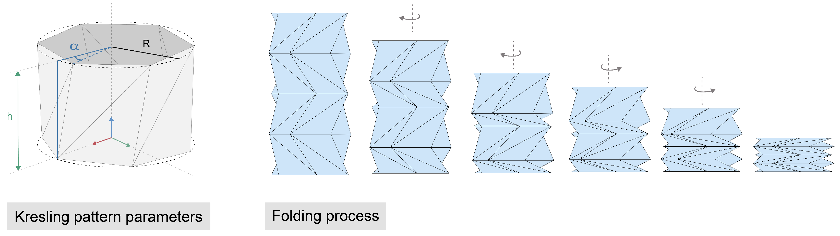
For the proper development of the proposed simulations, every surface in an opto-mechanical model shall be defined as close as possible to how it behaves in the real world. BSDF, which stands for Bidirectional Scattering Distribution Function, is the most accurate and extended method of defining how light behaves upon hitting an optical or mechanical surface from a radiometric perspective. This function is especially relevant for this analysis since we are using a standard black paint commonly used for blackening of optical baffles. Furthermore, BSDF is the way ASAP understands how light behaves after hitting an optical or mechanical surface covered with coatings, paints, etc. Commonly, the BSDF is presented with one or several inputs in terms of the angles of the incident light and the outputs (see Figure 2), which are the responses to that incident light presented in the chart with lines 1 through 4. These lines represent the angles at which the light is scattered for every angle of incident light and the energy related to that angle.
Figure 2.
BDSF model for CHEM306M obtained from ASAP software.
For the purpose of this analysis, we use CHEM306M BSDF over the origami baffle’s internal face as the black treatment that will produce the pertinent scattering effects that we want to compare against the conventional cylindrical baffle.
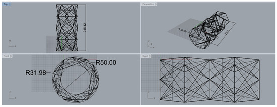
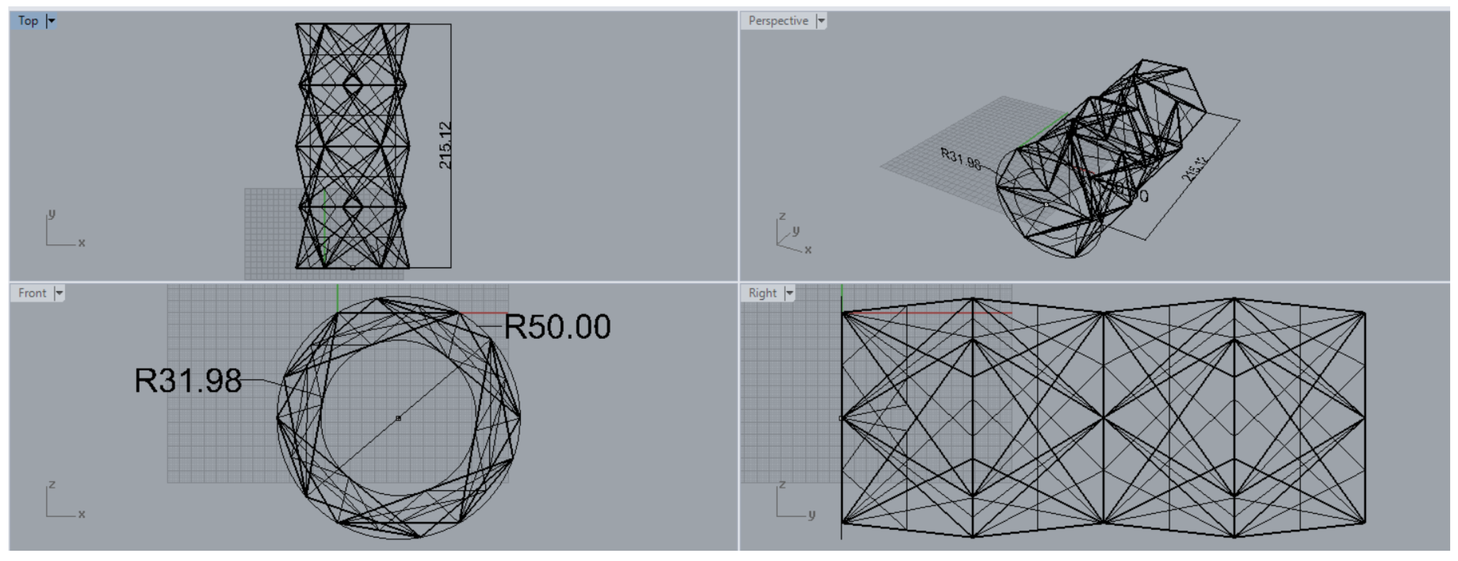
Rhino 6 was used to determine basic parameters of the origami baffle (see Figure 3), such as length and apertures, and to estimate the FOV limitation, which is approximately 16.9 (), where d stands for detector diameter, and f stands for focal length of the system, as well as to seamlessly import it to ASAP.
Figure 3.
Kresling model with measurements in Rhino 6 (2018) software.
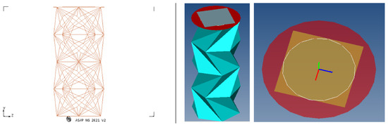
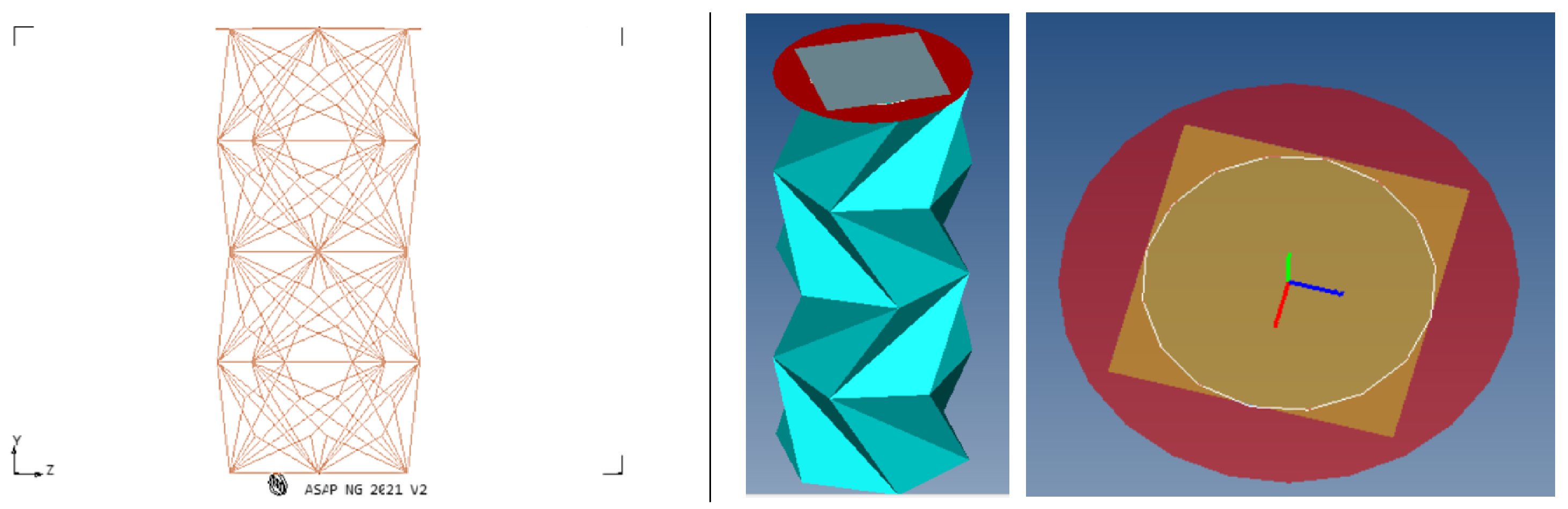
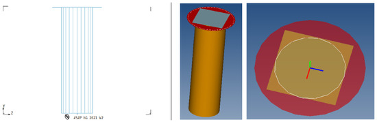
The model for the origami baffle simulations, see Figure 4 right, can be composed by a support surface (in red), an edge (in white), the detector (in gray/orange) and the CHEM306M blackening treatment in the internal faces. The white edge included is a feature from ASAP that forces scattered light to go through it, which enhances the scattering effects. Scattering effects are also enhanced by LEVEL 3, another ASAP feature, which allows a single ray to be re-scattered up to three times.
Figure 4.
ASAP model for Kresling origami model (left) and ASAP analysis features (right).
On the other end of the origami baffle, we place an extended incoherent source with a collimated beam. The main idea is to rotate this source and collect all the light, both scattered and straight from the source, on the other end, in the detector.
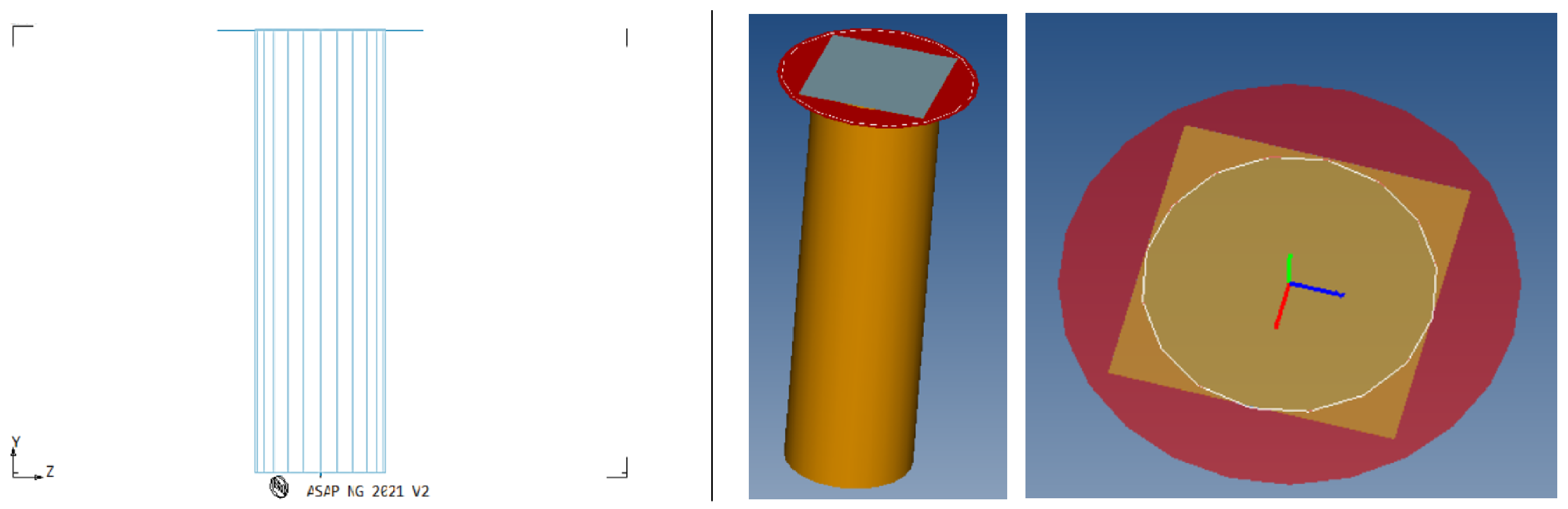
The procedure for the conventional cylindrical baffle was identical to the one already introduced (see Figure 5). Built from the CAD model, composed by a cylinder with the same FOV limitation as the origami baffle, a support surface (in red), an edge (in white), the detector (in grey/orange), and the black paint in the internal face of the cylinder. In addition, the incoherent extended source was located at the other end of the baffle and was rotated the same angles.
Figure 5.
ASAP model for conventional tubular model (left) and ASAP analysis features (right).
3. Results
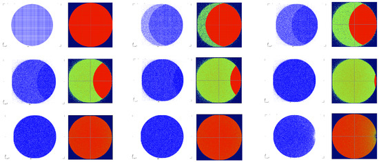
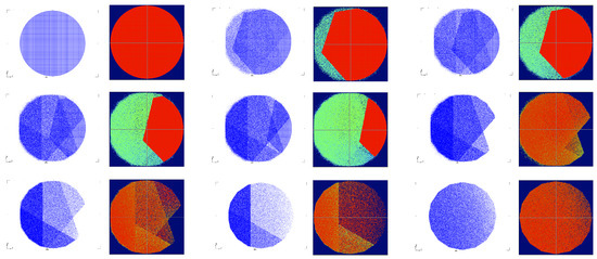
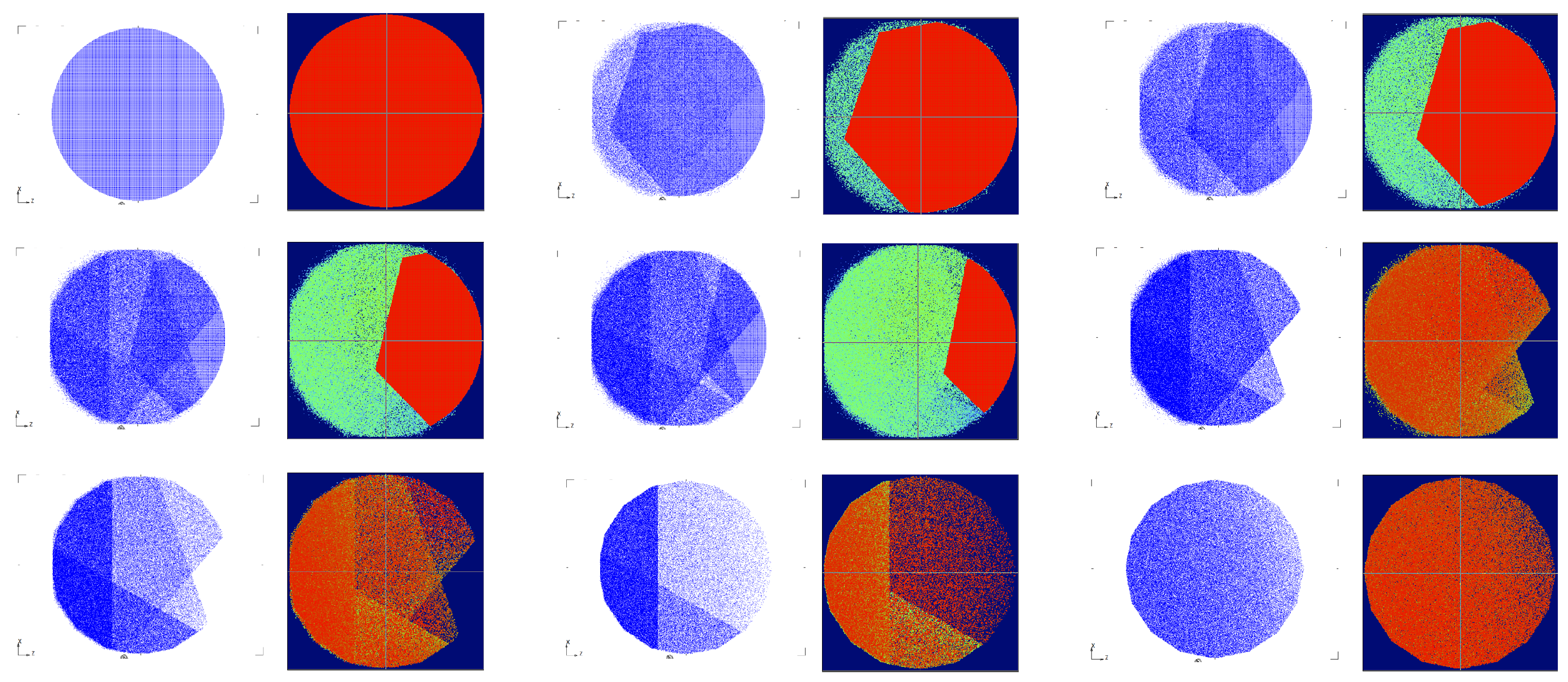
For both proposed baffle models, we obtained from the simulations the Impact Diagram Capture and the detector image (in a red to blue diagram), where flux geometry and intensity are obtained, respectively (see Figure 6 and Figure 7). As the results are acquired by rotating the light source in the azimuth angle, we therefore compare the evolution for the conventional and origami proposed baffles.
Figure 6.
Tubular baffle Impact diagram capture (blue geometry) and detector image (red to blue diagram).
Figure 7.
Kresling baffle Impact diagram capture (blue geometry) and detector image (red to blue diagram).
The conventional tubular baffle shows a light pattern evolving as represented in Figure 6, where the rotation of the light source can be traced in a straightforward manner: a crescent moon shape appears over the light received by the sensor as the angles increase. From 0 to 60 degrees the impact diagram and intensity are obtained and represented here.
On the other hand, the proposed origami geometry in its deployed shape modifies the light pattern in both shape and magnitude. Nonetheless, the light mostly follows a similar path as it did in the conventional baffle: the inclination angle traces the shape of the external border of the cylinder at the sensor, creating a hexagonal shape instead of the crescent moon shape from before. At the same time, there are some percentage of rays that are reflected and bounce between the different flat surfaces appearing inside the origami baffle, i.e., at the oris or triangles. Hence, the sensor receives stray light in a non-linear way, being mostly shielded by the shape of the baffle after a beam angle of 20°.
In Figure 7 we can see this evolution by varying the rotation angle, obtaining the described geometric shades and patterns. Due to all the inner flat faces of the pattern, the diagram inherit triangle-shaped shades, caused by light strikes in any of the faces and bounces towards the detector area. In the same manner, light can be repelled towards the exterior by the very same faces depending on their angle and inclination, thus the non-linear evolution of the percieved light intensity at the sensor.
From the angle variation analysis we can conclude how stray light is shielded by the origami shape and the patterns it forms when it reaches the sensor. The final analysis will be in terms of light intensity (radiated flux or irradiance, in W/mm2).
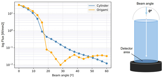
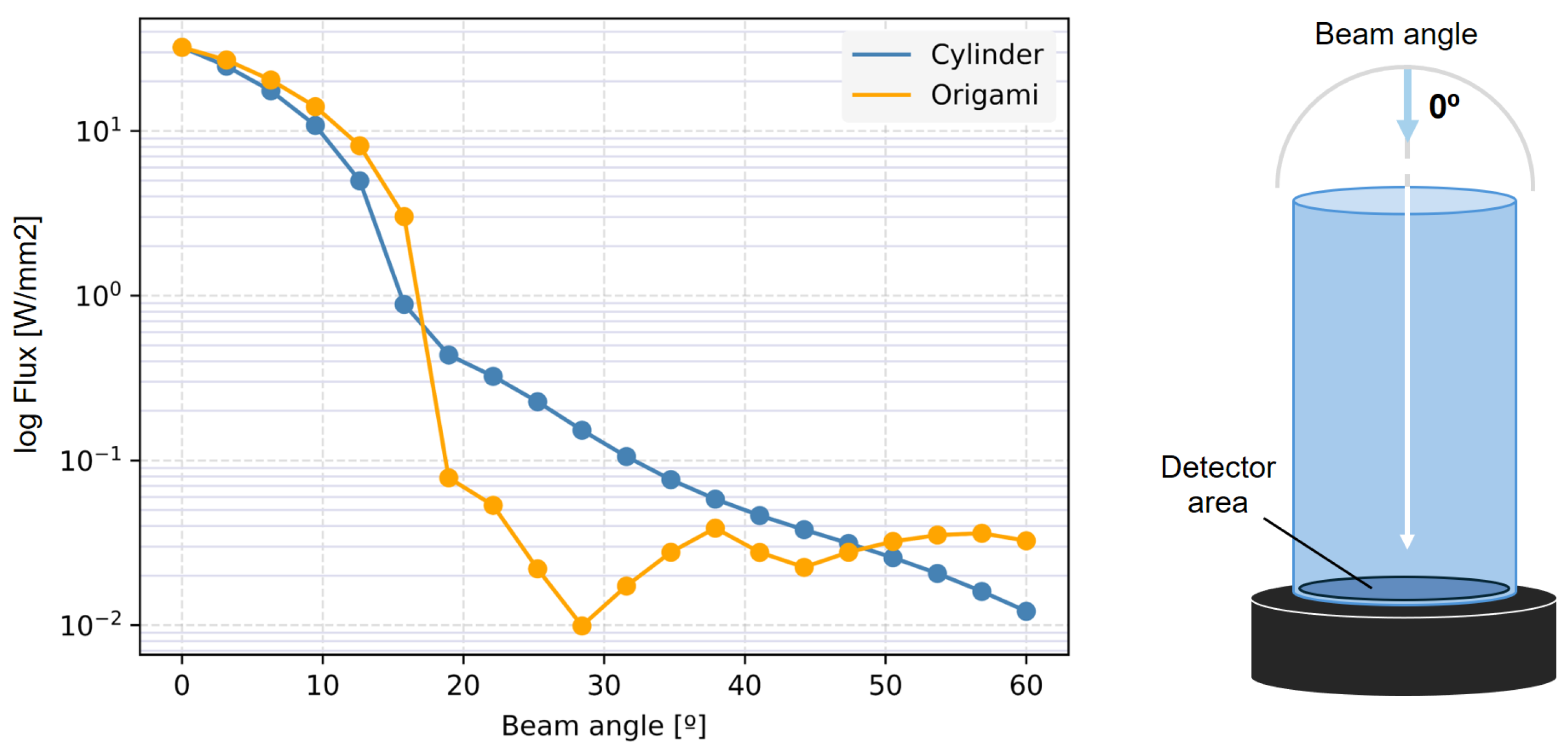
In order to obtain this value, we integrate the light collected by the sensor for each of the beam angles, for each of the baffles (conventional and origami), as presented in Figure 8. It is important to note that the results illustrated here are shown in logarithmic scale, in order to clearly show the angles for which the stray light is fully shielded and the order of magnitude of that shielding.
Figure 8.
Flux intensity in front of beam angle for conventional baffle (blue) and Kresling origami baffle (yellow) and graphic representation of the beam angle rotation.
In Figure 8 we can see the expected non-linear, irregular drop presented by the Origami shape. This behavior is caused by the inner shapes and their reflections, that allow for a higher, sudden, shielding once a certain angle is passed. Hence, the sensor is shielded from stray light that enters the baffle at angles higher than 15º. This non-linear, irregular behaviour is recovered also for higher angles, indeed, the more inclined the stray light is, the more it will bounce and reflect on the inner shapes. As a result, it can be concluded that, after this initial study, behaves better for fields close to FOV (10° to 20°), with a higher drop than the conventional baffle.
Overall, the origami baffle with the Kresling pattern shows an optical performance comparable to the conventional geometry, showing an irregular, non-linear drop and behavior in terms of light shielding. And this irregularity is directly caused by the shape of the oris, showing an improvement path of the pattern distribution: the geometry can be rethought to enhance the shielding in some specific angles without a mayor penalty on structural response or volume packaging. And, from this exploratory optical analysis, it can be concluded that the pattern and the overall structure is suitable for the design of a deployable telescopic baffle. Indeed, as an analogy, the patterned inner faces within the geometrical origami behave in a similar way as the conventional vanes, reducing the stray light for some angles.
4. Conclusions
An optical and structural comparison between a conventional and an origami deployable baffle has been performed, in order to assess the performance of the latter. While simple and robust, it has been shown that the conventional shape behaviour can be matched with an origami-like shape, that improves shape and volume. Moreover, the studied configuration presents an irregular, non-linear stray light shielding, showing that non only a similar optical performance than the conventional baffle is possible but also to enhance it. This can be achieved by modifying the geometrical origami parameters that define the pattern in a similar manner as the addition of vanes in the conventional one.
Hence, a coupled parametric optical and geometric analysis is required to see the optimal shapes for the stray light problem. This parametric analysis should also include a final validation stage where structural and deployment are studied, proving that it can be suitable for a spacecraft structural element. Therefore, the final configuration will be a trade-off between optimal optical, volumetric and structural performance.
All of the analyses described in this study have been obtained through numerical models assuming an ideal geometry without clear joints or manufacturing inhomogeneities. Thus, for further analysis, uncertainty quantification and the inclusion of more realistic models are required. At the same time, an experimental validation is being designed for a more complete study. This test campaign will be performed in an optical test bench replicating the conditions implemented in the simulation software for different geometries, materials, and inner coatings.
Author Contributions
Conceptualization, E.V.-N., P.S.-L. and R.S.; methodology, T.B. and D.R.-D.; software, T.B. and D.R.-D.; formal analysis, T.B.; investigation, E.V.-N. and P.S.-L.; resources, R.S. and T.B.; data curation, D.R.-D.; writing—original draft preparation, E.V.-N., P.S.-L. and D.R.-D.; writing—review and editing, R.S.; visualization, E.V.-N. and D.R.-D.; supervision, P.S.-L. and R.S.; project administration, P.S.-L. and R.S.; funding acquisition, R.S. All authors have read and agreed to the published version of the manuscript.
Funding
This research was funded by FICS-1, founded by PID2020-115325GB-C31 MCIN/AEI/10.13039/501100011033.
Institutional Review Board Statement
Not applicable.
Informed Consent Statement
Not applicable.
Conflicts of Interest
The authors declare no conflicts of interest. The funders had no role in the design of the study; in the collection, analyses, or interpretation of data; in the writing of the manuscript; or in the decision to publish the results.
Abbreviations
The following abbreviations are used in this manuscript:
| BSDF | Bi-directional Scattering Distribution Function |
| FOV | Field of view |
References
- Hu, X.; Wang, W.; Hu, Q.; Lei, X.; Wei, Q.; Liu, Y.; Wang, J. Design of CASSEGRAIN telescope baffles with honeycomb entrance. Chin. Opt. Lett. 2014, 12, 072901. [Google Scholar] [CrossRef] [Scilit]
- Yalagach, A.; Honeth, M.; Gandhi, R.; Aglietti, G.S.; Ingram, C.; Saxena, A. Development of a deployable mechanism for a conical optical baffle for a small satellite. Adv. Space Res. 2024, 73, 870–884. [Google Scholar] [CrossRef] [Scilit]
- Velázquez-Navarro, E.; Solano-López, P.; Uriol-Balbin, I. Preliminary Design and Optimization of a CubeSat Demonstrator for an Origami-inspired Deployable Structure. In Proceedings of the AIAA SciTech Forum and Exposition, Orlando, FL, USA, 8–12 January 2024. [Google Scholar] [CrossRef] [Scilit]
- Guest, S.D.; Pellegrino, S. The Folding of Triangulated Cylinders, Part I: Geometric Considerations. J. Appl. Mech. 1994, 61, 773–777. [Google Scholar] [CrossRef] [Scilit]
- Sachithanandan, J.; Uriol-Balbin, I.; Solano-Lopez, P. Preliminary Design of a CubeSat Demonstrator for an Origami-inspired Deployable Structure. In Proceedings of the 74th International Astronautical Congress, IAC, Baku, Azerbaijan, 2–6 October 2023. [Google Scholar]
- Uriol-Balbin, I.; Solano-López, P. Preliminary Study of An Origami-inspired Deployable Structure for a Small-Scale Demonstrator. In Proceedings of the 73rd International Astronautical Congress, IAC, Paris, France, 18–22 September 2022. [Google Scholar]
- Yang, M.; Grey, S.W.; Scarpa, F.; Schenk, M. Large impact of small vertex cuts on the mechanics of origami bellows. Extrem. Mech. Lett. 2023, 60, 101950. [Google Scholar] [CrossRef] [Scilit]
- Kempenaers, M.; Vandepitte, D. Deployable structure for a CubeSat-based Cassegrain telescope. J. Astron. Telesc. Instrum. Syst. 2025, 11, 024002. [Google Scholar] [CrossRef] [Scilit]
Disclaimer/Publisher’s Note: The statements, opinions and data contained in all publications are solely those of the individual author(s) and contributor(s) and not of MDPI and/or the editor(s). MDPI and/or the editor(s) disclaim responsibility for any injury to people or property resulting from any ideas, methods, instructions or products referred to in the content. |
© 2026 by the authors. Licensee MDPI, Basel, Switzerland. This article is an open access article distributed under the terms and conditions of the Creative Commons Attribution (CC BY) license.