


Abstract
Safety is the most critical asset in the aerospace industry, and emerging technology domains like hybrid-electric distribution systems present new challenges. In this context, digitalization plays a crucial role in analyzing and managing different safety aspects within and across companies. This study shows that tools and methods can integrate seamlessly by interfacing safety data throughout aircraft development stages, using standardized representations of digital artifacts. We further argue that the approach can be utilized to provide evidence of regulatory compliance to third parties, such as certification authorities, thereby supporting the certification process and investigations into the certifiability of disruptive technologies.
1. Introduction
Safety is the most fundamental asset in the aerospace industry, serving as the foundational principle that underpins all its engineering activities. With advancements towards new disruptive technologies, like hybrid-electric distribution systems, the quest for safety requires engineering practices to consider aspects that go beyond traditional processes, accounting for ever more complex system interactions and coping with the challenges posed by limited domain experience and historical know-how of novel contexts. For this reason, development processes of aircraft systems shall follow standard safety practices coherently, ensuring an integral approach from the initial phases of development, through implementation, and into operation and maintenance.
With the ongoing trend towards digitalization, it is anticipated that various tools be required by different teams across different development phases, possibly supporting interactions between supply chain actors like aircraft integrators and system developers. For these tools to function properly in a digital thread [1], a clear definition of interfaces and activities at every stage of the development lifecycle is needed, so that inputs and outputs are well defined and users can rely on well specified contracts of use.
In the realm of safety analyses, digital methods such as Model-Based Safety Analysis (MBSA) have a well-documented history, both in the academic literature and industrial practice, and numerous tools and methodologies are available based on different process needs [2,3]. To make this effective, methods require development processes to be standardized, requiring similar inputs, such as systems architectures, and producing similar outputs, such as fault trees or Failure Mode and Effects Analysis (FMEA) tables. We therefore advocate for a standardized approach that can handle different types of safety artifacts, with varying levels of specificity based on different use cases, phases of development, and safety processes. While doing this, we contextualize our approach with respect to existing modeling standards, such as the OMG RAAML (Risk Analysis and Assessment Modeling Language) [4].
While considering different actors requiring the exchange of artifacts, we maintain that the definition of their lifecycle should be defined with loose dependence on internal company processes, since they may own lifecycle activities to support internal digital thread workflows. Correspondingly, the identification of safety artifacts to be exposed at the collaboration boundary, as well as their lifecycle and the platform for the exchange, is left to the involved companies’ engagement arrangements.
Following the tradition of the commonly referred digital thread technologies [1], we aim to integrate safety data and information throughout the design cycle. Advancing the previous literature, we propose a method that positions safety artifacts at the center of the engineering method, enabling robust digital system engineering where different safety artifacts and views can help inspect and support the end-to-end development of aircraft systems at different levels.
The contribution of this paper is twofold. First, it proposes the use of an extensible set of artifacts relevant for safety analyses, accounting for their relationships, drawn from real industry use cases. Second, it proposes the notion of a Digital Safety Thread (DST) to connect the use of different tools for specific safety activities, and ensure seamless data exchange between them, using standard artifacts as interfaces between development steps. As we discuss below, the implementation of the DST enables a common interpretation of the interchanged artifacts, by a consensus on the appropriate method for orchestrating these artifacts within the development process and by seamless tool integration to represent, manage, version, and exchange them effectively. By centering this effort on safety aspects integral to development, our approach introduces a novel perspective.
We illustrate the proposed approach using the process of ARP4754B/ARP4761A [5,6] as a reference, showing how interfaces between aircraft integrator, system supplier, and subsystem supplier are defined to support the subsequent safety analyses. As we define the approach, we propose to link different safety analysis tools and methods in the DST. The generated links can thus support the traceability between artifacts and assist in activities beyond safety analysis, such as impact assessment.
We further argue that the approach can be employed in contexts where the generated artifacts need to be vetted as compliance data by third parties, such as certification authorities, thus supporting the certification process. Additionally, it can be applied in scenarios where the generated artifacts are used to investigate the certifiability of disruptive technologies. As an application for future developments, we discuss the role of digital twins to reinforce the validity of the generated artifacts.
2. Definition of the Method
We define the Digital Safety Thread (DST) as a digital asset to create and evolve safety artifacts within the boundaries of a company and across companies, enabling collaboration with external parties. The DST is intended to be integral to product development, in a sense similar to what is defined as integral by regulatory standards such as ARP4754B/ARP4761A [5,6]. It is thus intended to span across the design lifecycle of end-to-end systems, providing digital links between internal practices of individual companies.
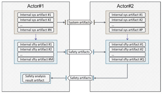
The proposed method builds on the concepts represented in Figure 1, which show how different actors can interact using a standard schema. This schema is part of our method, and it builds on the observation that in the context of a DST, each actor may hold internal processes and toolchains to implement an internal position of the DST, then expose selected or protected subsets of artifacts to be exchanged with other parties.
Figure 1.
Abstract conceptualization of Digital Safety Thread (DST) interactions (static view).
Artifacts in the light-brown shading in Figure 1 are associated with system-level activities. These artifacts could be requirement representations, models, legacy systems, analysis reports, traceability relationships, and others. Artifacts in the light-blue shading are associated with safety activities. Examples could be reliability models, fault trees, and FMEA tables. Safety activities may use system artifacts belonging to that actor’s scope to create the safety artifacts (represented as purple dashed arrows).
At the interface between actors, system artifacts and safety artifacts are exposed, informing the corresponding system or safety activities. The involved actors shall define formal agreements regarding the scope and format for the exchanged artifacts. In order to efficiently implement the DST, interfaces between parties should be clearly defined and ideally be formatted according to data representation standards, so as to make them amenable for exchange reuse, configuration management, and Long-Term Archival and Retrieval (LOTAR) [7,8]. On the other hand, artifacts maintained within the scope of individual companies need not comply with the standard formats, as they will lay outside the context of the cross-company portion of the DST.
We note that the indicated pattern of Figure 1 does not include the time dimension and thus it does not consider (a) evolutions of the same system or safety artifacts during the engineering process with relative dependencies and (b) exchange of diverse sets of system or safety artifacts throughout time. We call the corresponding view “static” because the actual exchanges may happen at different points in time and not necessarily in synchronous ways. The involved actors are responsible for determining the evolution of the involved artifacts and the frequency for their exchange.
The final DST is represented by the full set of product design data, with enabled traceability across virtual space and time and among all involved actors. This allows for seamless, access-controlled inspection of safety information, integral with respect to system design.
3. Application Example
3.1. Applicability to Standard Processes
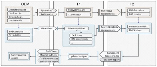
To demonstrate the instantiation of the method using a concrete example, we provide a setup where three companies interact: an aircraft integrator (hereafter named OEM for “Original Equipment Manufacturer”), an aircraft system supplier (hereafter named T1 for “Tier1”), and an aircraft subsystem provider (hereafter named T2 for “Tier2”). The corresponding static view of the DST is represented in Figure 2, showing a non-exhaustive set of artifacts exchanged between OEM, T1, and T2.
Figure 2.
Instantiation of the DST involving three actors using the ARP4761A processes (static view).
In this study, only a few of all of the system and safety artifacts exchanged between the parties above are used to illustrate the ideas of our work while keeping the scope self-contained. These are described as follows:
1. Failure Conditions, from the OEM to T1. Failure conditions are developed by the OEM according to an internal SFHA (System Functional Hazard Assessment) process. They are part of an OEM-internal DST and kept consistent with other artifacts such as the aircraft function list and the system function list and with PASA (Preliminary Aircraft Safety Assessment) artifacts. For this example, we assume that T1 has no involvement in the definition of SFHA tables.
2. Safety requirements, from T1 to T2. The derivation of safety requirements is based on the execution of the PSSA (Preliminary System Safety Assessment) process. This process makes use of artifacts that are part of the Digital Safety Thread of T1. The safety requirements are in fact derived from the PSSA process and then passed on to T2 to build the cross-company portion of the DST.
3. Component failure modes and FMEA (Failure Mode and Effect Analysis)/FMES (Failure Mode and Effect Summary) tables, from T2 back to T1. These are derived from standard practices and can be supported by safety analysis tools. Once received, this information is used by T1 and fed into fault trees for the PSSA process, later to be evolved into fault trees of the SSA (System Safety Assessment) process.
4. Fault trees and minimal cut sets, from T1 back to OEM. This information, created during the PSSA process and later refined to the SSA process, will be provided to the OEM as part of the safety objective satisfaction report. The OEM will use this material to inform fault trees and safety artifacts of their internal DST, sustaining the ASA (Aircraft Safety Assessment) process and preparing the final report to be vetted by certification authorities.
3.2. Custom Profile for Safety Artifacts Modeling
A custom SysML profile was built on top of OMG RAAML, with extensions to support the formalization of all safety artifacts required for running the DST concept and workflow on internal company examples. Table 1 outlines the SysML profiles used to model the safety artifacts exchanged in Figure 2. Although the approach is general, we focus on the artifacts at the interface between actors and their format, since those typically require consensus between parties.
Table 1.
Representation of safety artifacts for demonstrating DST concepts and workflow.
We focus on five safety artifacts in Table 1, two of which, i.e., Safety Requirement and Fault Trees, are directly supported by the OMG RAAML profile and used as is. The other three artifacts required an extension of the standard by using a custom profile, which we next describe.
The SFHA summary table, provided by the OEM to T1 as shown in Figure 2, is modeled as a custom table in which each row is represented as an FHA Item in SysML using a custom extension built on OMG RAAML. Each FHA Item is characterized by the following attributes: Failure condition, Failure Effect, Flight phase, and Classification. This modeled safety artifact can support traceability of fault tree top-level events created by T1 during PSSA or SSA, and the failure conditions created by OEMs in the SFHA process.
The component failure modes are represented using an FMES table that is composed of Id, Failure Mode, Failure Rate, Cause of Failure, and Detection Control. Using toolset capabilities, the Failure Rate value can be displayed automatically as an attribute of Failure Mode. We remark that despite the concept of Failure Mode being supported by OMG RAAML, modeling the concept of an FMES table and its attributes required the creation of a custom table and an extension of the failure mode concept, by introducing the attributes required to represent the table, such as that of failure rate. The information about FMES from T2 enables T1 to refine the FTA (Fault Tree Analysis).
The minimal cut sets (MCSs) are often presented as part of the results of an FTA and are used to support evidence for safety processes. In this extension, we defined the construction for MCSs with lists of basic events (readily taken as defined by OMG RAAML) and relative cut set probabilities. Under the assumption of basic event independence, these probabilities are calculated by custom scripts, by multiplying the probability values of the basic events in individual cut sets. We note that by representing the concept of cut set to be independent of that of fault tree, we could also define independent aggregations of MCSs, of which summed values could be taken to compute the total probability relative to the occurrence of any of them. Moreover, with an independent concept of cut sets, additional features like importance measures (e.g., Birnbaum, Fussel–Vesely measures [9]) could be defined.
We note that within the above setting, the use of a standard representation for the exchanged artifacts becomes critical. Moreover, the exchange of the above safety artifacts and their traceability should evolve with development and should happen at pre-defined program milestones during development, in agreement with program plans.
4. Discussions
4.1. Applicability and Extension of the Approach
We have shown a simple expository application of the approach using a workflow inspired by ARP4761A processes. The pilot application of this process highlighted the challenges associated with integrating diverse tools and processes, which lead us to emphasize the use of standards, as discussed in Section 3.2. We also noted the critical need to adhere to internal company processes to ensure an effective deployment of the DST. In this context, adapting to standard formats agreed upon with sharing partners emerges as an essential requirement. For novel digital approaches or internal artifact formats not tied to legacy processes, we recommend aligning with standardized formats to preemptively eliminate challenges due to artifact adaptation.
We plan to extend the basic principles of the DST in several ways.
First, additional artifacts could be included, considering those related to Cascading Effect Analysis, Common Mode Analysis, Zonal Safety Analysis, Particular Risk Analysis, and others. For these types of extensions, understanding the aspects to be included as part of the DST requires identifying their scope and a suitable representation, as well as to understand how they fit into the overall design cycle.
Second, the approach could be broadened by considering data and relational representations of safety artifacts beyond a self-contained (set of) modeling environment(s), by extensions to full digital data platforms integrated with other systems and business needs.
Third, the approach could be extended towards aspects of manufacturing and production, as well as maintenance, operations, and continued airworthiness until dismissal. This would require tracking the evolution of the product and its safety footprint for its entire lifecycle, which would require a strong and robust digital infrastructure, as well as alignment of team skills throughout the development.
Finally, it would be interesting to find the applicability of the DST concept to other industry domains which may need to follow different safety standards, such as ISO26262 for the Automotive domain and Safety Of The Intended Functionality (SOTIF) extensions [10], and to investigate the safety impact of human factors when given in the context of a DST.
4.2. Application to Certification Processes and Digital Twin Extensions
There is a concerted effort within the aerospace industry to digitalize the certification process. In Europe, this effort is being undertaken by the EASA Stakeholders Advisory Body (SAB) group AG.002, among others. DSTs can support one of the main objectives of this initiative, which is to transition from document-centric exchanges to data-centric exchanges for a digital certification process. Safety artifacts are required to be shared with the safety regulators to demonstrate compliance with Certification Specification (CS) requirements (MoC 3) in a certification program. This exchange is traditionally done through documents. In the future, this could be achieved by directly sharing digital artifacts with the safety regulators, or by reporting selected views of the DST and traceability links.
It shall also be noted that safety artifacts play a significant role in the pre-application phase of an aeronautical product, as highlighted in the Certification Readiness Level (CRL) scale [11]. The CRL scale provides a structured approach to evaluate and track the progression of an innovative product’s readiness for certification. The CRL guidelines are particularly beneficial during the pre-application phase, as they help applicants identify and mitigate potential risks in the certification program by engaging with relevant stakeholders, including the safety regulator. During this phase, safety artifacts can be shared with the safety regulator to reach an agreement on the primary risks associated with new technologies or concepts of operation incorporated in the innovative product.
We argue that the use of DSTs in the pre-application phase for the type certificate can be beneficial for two main reasons: (1) It can facilitate the exchange of artifacts between the integrator and the safety regulator. (2) It can support the evolution of safety artifacts throughout the product lifecycle and the product certification maturation by efficiently evaluating design changes and incorporating them into updates to the safety artifacts.
We envision that during the pre-application phase, an integrator may use digital twin technologies [12] to support the certifiability assessment. In this context, safety artifacts can enrich a digital twin by providing information about failure modes and their impact on system behavior [13]. With this information, a digital twin can be used to explore the system’s operational domain and gain insights that could trigger a reassessment of safety artifacts. For example, identifying new failure propagation paths in the digital twin could impact fault trees or FMEA tables, leading to a reassessment of the design against the criticalities of failure conditions. This allows for the validation and re-evaluation of failure condition criticalities, which need to be agreed upon with the certification authority.
We thus outline two approaches for using a digital twin in this context: (1) the integrator performs a virtual integration of digital twin solutions provided by suppliers and (2) the integrator requires supplier digital twin data to autonomously create the digital twin. In this latter case, the integrator needs to track the type of information shared with the supplier. Maintaining information traceability and performing a data quality assessment are essential to establish a credibility framework for the digital twin.
Both approaches can present challenges when considered in the context of a certification process. One significant challenge is to effectively communicate relevant information between parties while ensuring the protection of intellectual property. In fact, depending on the intended use of the digital twin and the effort required for its validation, the integrator, or even the certification authority, may need to access specific information that a supplier would need to protect. Therefore, it is crucial for the parties to collaboratively identify the full set of information required to support the certification. The presence of standardized artifacts in a DST, although unlikely to completely resolve this issue given the wide range of possible uses for a digital twin, could nonetheless serve as a starting point to facilitate discussions between integrators and suppliers.
5. Conclusions
In this paper, we described an approach to formalize safety artifacts within company boundaries and at the interface between companies, relying on the concept of a Digital Safety Thread (DST). We discussed how this approach can support the end-to-end development of aircraft systems, placing the safety aspects in a central position with respect to digital engineering practices.
As future work, we argued that the approach can be extended to account for additional types of artifacts, extended product lifecycles, and supporting technological platforms, as well as for possibly supporting the existence of digital artifacts in the certification process. As future work, we also plan to derive precise requirements to effectively support these processes and to ensure the validity of the safety artifacts with a level of rigor appropriate to the criticality of their use.
Author Contributions
Conceptualization, L.D.L., M.D., L.D.G., and V.P.; methodology, L.D.L.; writing—original draft preparation, L.D.L., M.D., and V.P.; writing—review and editing, L.D.L., M.D., L.D.G., and V.P.; visualization, M.D. All authors have read and agreed to the published version of the manuscript.
Funding
This research was funded by the European Union under GA no 101101961—HECATE. The views and opinions expressed are however those of the author(s) only and do not necessarily reflect those of the European Union or Clean Aviation Joint Undertaking. Neither the European Union nor the granting authority can be held responsible for them. The project is supported by the Clean Aviation Joint Undertaking and its Members.
Institutional Review Board Statement
Not applicable.
Informed Consent Statement
Not applicable.
Data Availability Statement
No new data were created or analyzed in this study.
Conflicts of Interest
Author Loris Dal Lago, Marco Donnarumma, Luigi Di Guglielmo, and Vincenzo Petrella were employed by the company Collins Aerospace.
Abbreviations
The following abbreviations are used in this manuscript:
| ASA | Aircraft Safety Assessment |
| CAD | Computer-Aided Design |
| CRL | Certification Readiness Level |
| CS | Certification Specification |
| DAL | Development Assurance Level |
| DST | Digital Safety Thread |
| FMEA | Failure Mode and Effects Analysis |
| FTA | Fault Tree Analysis |
| HW | Hardware |
| MBSA | Model-Based Safety Analysis |
| MCS | Minimal Cut Set |
| MoC | Means of Compliance |
| OEM | Original Equipment Manufacturer |
| OMG RAAML | Object Management Group—Risk Analysis and Assessment Modeling Language |
| PASA | Preliminary Aircraft Safety Assessment |
| PSSA | Preliminary System Safety Assessment |
| SFHA | System Functional Hazard Assessment |
| SOTIF | Safety Of The Intended Functionality |
| SSA | System Safety Assessment |
| T1 | Tier-1 supplier |
| T2 | Tier-2 supplier |
References
- Singh, V.; Willcox, K.E. Engineering design with digital thread. Aiaa J. 2018, 56, 4515–4528. [Google Scholar] [CrossRef] [Scilit]
- Lisagor, O.; Kelly, T.; Niu, R. Model-based safety assessment: Review of the discipline and its challenges. In Proceedings of the 2011 9th International Conference on Reliability, Maintainability and Safety, Guiyang, China, 12–15 June 2011. [Google Scholar]
- Sun, M.; Gautham, S.; Ge, Q.; Elks, C.; Fleming, C. Defining and characterizing model-based safety assessment: A review. Saf. Sci. 2024, 172, 106425. [Google Scholar] [CrossRef] [Scilit]
- OMG. RAAML—Risk Analysis and Assessment Modeling Language v1.1. 06 2024. Available online: https://www.omg.org/spec/RAAML (accessed on 1 June 2025).
- ARP4754B; Guidelines for Development of Civil Aircraft and Systems. SAE International: Warrendale, PA, USA, 2023.
- ARP4761A; Guidelines for Conducting the Safety Assessment Process on Civil Aircraft, Systems, and Equipment. SAE International: Warrendale, PA, USA, 2023.
- Coïc, C.; Murton, A.; Mendo, J.C.; Williams, M.; Tummescheit, H.; Woodham, K. Modelica, FMI and SSP for LOTAR of Analytical mBSE models: First Implementation and Feedback. In Proceedings of the 14th Modelica Conference 2021, Linköping, Sweden, 20–24 September 2021. [Google Scholar]
- Frechette, S.; Paul, H.; Mark, C. Model Based Enterprise Technical Data Package Requirements; National Institute of Standards and Technology, US Department of Commerce, NIST: Gaithersburg, MD, USA, 2011. [Google Scholar]
- Modarres, M.; Kaminskiy, M.P.; Krivtsov, V. Reliability Engineering and Risk Analysis: A Practical Guide; CRC Press: Boca Raton, FL, USA, 2016. [Google Scholar]
- Pimentel, J. Safety of the Intended Functionality; SAE International: Warrendale, PA, USA, 2019; Volume 3. [Google Scholar]
- EASA. Innovation Services—‘Certification Readiness Level’ Scale. Available online: https://www.easa.europa.eu/en/document-library/application-services/innovation-services#goodtoknow (accessed on 5 June 2025).
- ISO 23247-1: 2021; Automation Systems and Integration–Digital Twin Framework for Manufacturing–Part 1: Overview and General Principles. ISO: Geneva, Switzerland, 2021.
- Aievola, R.; Cumbo, R.; Di Guglielmo, L.; Donnarumma, M.; Iovino, S.; Lazzara, L.; Petrella, V.; Sinisi, S.; Ulisse, A. Reducing the Risk Associated with Certifiability of New Technologies Through Safety-Informed Scenarios for Aircraft Design Validation. In Proceedings of the TSAS 2025—Towards Sustainable Aviation Summit, Toulouse, France, 28–30 January 2025. [Google Scholar]

Disclaimer/Publisher’s Note: The statements, opinions and data contained in all publications are solely those of the individual author(s) and contributor(s) and not of MDPI and/or the editor(s). MDPI and/or the editor(s) disclaim responsibility for any injury to people or property resulting from any ideas, methods, instructions or products referred to in the content. |
© 2026 by the authors. Licensee MDPI, Basel, Switzerland. This article is an open access article distributed under the terms and conditions of the Creative Commons Attribution (CC BY) license.