


Abstract
The weight of battery modules keeps hindering them from being commercially attractive as the sole power supply for short-range electric passenger flights. Furthermore, the challenging requirements for aerospace applications limit the range of options for module elements and complicate the implementation of lightweight solutions. Hence, the objective of this study is to elaborate and evaluate concepts for battery modules to identify promising solutions for electrified aircraft propulsion systems. For that purpose, a house of quality is compiled to assess the relations between options for module elements and module requirements, as well as correlations between options. Potential concepts are elaborated by combining suitable elements. Finally, the concepts are evaluated to highlight the most preferable and compatible ones for aircraft battery modules.
1. Introduction
Within the scope of the Flightpath 2050, the ACARE has set goals to reduce the climate impact of the aircraft industry. One promising concept to achieve these objectives is the transition to All-Electric Aircraft (AEA) powered solely by batteries [1]. However, current solutions cannot provide the energy required for the propulsion of a large AEA even for a short-range flight. To overcome this challenge, significant advancements are required for the energy density of the cells and the mass overhead at the module and pack levels [2].
This study provides an overview of module elements contributing to the mass overhead of battery modules. Based on that overview, a house of quality (HoQ) is compiled to elaborate and evaluate promising lightweight module concepts that integrate compatible elements.
2. Overview of State-of-the-Art Module Elements
Battery modules consist of various elements which can be summarised into the following groups: the battery as a stack of cells, structural elements for the protection from environmental factors and the fire insulation of the module, elements for the thermal management of the battery, mechanical elements for high strength, control elements for monitoring and regulation of the battery, and electrical elements for power transmission [3]. In the upcoming sub-sections, potential options for the module elements are explored.
2.1. Battery
In order to select a battery cell, it is necessary to define the cell type, size, and chemistry. Within the context of the module arrangement, the chemistry is neglected. However, it has to be considered in relation to the module requirements, given the variation in energy density and thermal behaviour across different chemistries [4].
2.1.1. Cell Type
Only cylindrical and pouch cells are considered, as prismatic cells are projected to offer comparatively low energy densities in the near-term future [4]. For integration into an AEA, at least 450 Wh/kg and 900 Wh/l are required at the cell level according to de Vries et al. [2] to enable a short-range flight of 800 km.
2.1.2. Cell Size
Common types of cylindrical cells are 18650 and 21700. The first two digits stand for the diameter (e.g., 18 mm) and the remaining digits for the height (e.g., 65.0 mm) of the cylindrical cells. The 4680 cell is an alternative variant characterised by increased height and thickness [5]. In contrast, pouch cell sizes range currently between 0.04 L [6] and 0.80 L [7]. Even though the cell size has been discussed in a prior publication [4], the thermal behaviour with regard to cell dimensions is of special interest and has been investigated by Pesaran et al. [8].
Their results demonstrate that the average temperature of cylindrical cells can decrease by ∼5 °C by reducing the volume. Using a larger base area while maintaining a constant volume for pouch cells is also advantageous, as the cooling surface increases and the thermal diffusion length in the thickness direction becomes shorter [9]. The positive impact of taller and thinner cylindrical cells is relatively low. Furthermore, smaller cells produce less heat during a thermal runaway (TR) event [8]. In summary, small cells are preferable compared to large cells, with regard to the thermal behaviour.
2.2. Structural Elements
Rothgang et al. [10] have highlighted the mass distribution of module elements for automotive applications. The elements with the greatest proportion, apart from the cells accounting for ∼70% of the total weight, are the cooling system and the encasing with ∼10% each. It should be noted that both of these elements play a critical role in TR mitigation.
2.3. Thermal Elements
2.3.1. Thermal Runaway Propagation Mitigation and Containment
Strategies for passive mitigation of TR propagation and TR containment include heat spreaders [11], phase-change material (PCM), and aerogel [12]. A heat spreader can distribute the heat from a single cell to the module to avoid hot spots [11]. PCMs are promising due to their ability to absorb a large amount of heat during TR, which is attributed to their high latent heat. An aerogel can serve as an additional insulation layer between cells, delaying the propagation of TR [12].
2.3.2. Cooling System
The selection of an appropriate coolant is necessary and it must be determined whether direct or indirect contact with the cells is preferred. The location of the cooling hardware can vary, being at the top, bottom, or sides of the cell stack, between the cells, or at the cell tabs. Furthermore, cooling strategies are divided into active and passive methods [4].
A common approach for cylindrical cells involves the utilisation of a cold plate, typically placed at the bottom face of the cell stack. Alternatively, a meander structure can be considered as well [13]. Moreover, Lai et al. [14] have introduced a novel approach in which the coolant flows from an upper reservoir on top to a bottom reservoir at the bottom of the cell stack, passing through a thermal conductive structure (TCS), which is aligned to the lateral area of the cells. In contrast, the thermal behaviour of pouch cells depends on the cell cooling coefficient (CCC) [15]. Pouch cells with a high CCC generate more heat in the base area, while a low CCC indicates hot spots at the cell tabs. Therefore, the optimal contact area of the cooling system is dependent on the cell type and size [15].
The cooling system also plays a critical role in meeting the TR requirements of the EASA [16]. Although a direct cooling system may seem appealing due to its simplicity, the use of natural convection by air is not sufficient at a C-rate above 1 C [17], which is an operating condition required for a short-range flight of a large AEA [18]. In comparison to direct air cooling systems, immersion cooling systems, which have been successfully tested at TR conditions, currently demonstrate a far too high mass penalty [19]. Two-phase cooling systems, such as those using PCM, are promising for mitigating TR as well. It has been proven that a hybrid cooling system consisting of a cold plate between adjacent cells and a PCM in contact with the base area of the cells can successfully prevent TR propagation [20]. However, the viability during normal operation must be analysed. Moreover, that hybrid cooling system resulted in a high mass penalty as well. An option may be to use a vapour cycle system which offers a potential for further weight reduction by replacing the single-phase cold plate of the aforementioned hybrid cooling system.
2.4. Mechanical Elements
2.4.1. Fixation
Pouch cells can be integrated into frame structures which can be glued to each other [21]. Alternatively, each cell with its frame can be stacked in a form-fit connection in a gap pad, allowing for compensation of cell expansion during operation [22]. In contrast, cylindrical cells are typically fixed using cell holders. Further options are heat-shrink tubing [11] and particle foam surrounding the lateral surface area of the cells [23].
2.4.2. Pressure Control
While pressure control is not necessary for cylindrical cells, given that the cell can is already providing compression, pouch cells require compression and compensation as they expand during operation [24]. One option for compensation is to utilise flexible adhesives, which also offer a range of benefits including the compensation of manufacturing tolerances for uniform compression and the protection against dust and moisture. Structural adhesives, in particular, stand out due to their high strength and uniform stress distribution, as well as enhanced thermal conductivity which improves heat transfer from the cell [25]. They can be placed between adjacent cells or between the base area of the cell and the cold plate, indicating their suitability for integration with all three cooling options mentioned earlier [24]. Pressure pads between adjacent cells are an alternative option for compensation, to maintain a pre-defined pressure range against the base area of the cell [17]. Flexible compression is hereby identified as a key factor, to increase the cycle life of the cells [26]. To achieve uniform compression, a pair of stiff compression plates connected with flexible tie rods or bolts can be used [27].
2.4.3. Venting
Even though cylindrical cells do have safety measures, such as a positive temperature coefficient and a current interruption device, to be used in case of TR, an additional venting channel is suggested to guide the gases from a harmed cell to the environment without affecting neighbouring cells. For pouch cells, a more sophisticated design is necessary as they do not have these inherent safety features [28]. At the cell level, the inner design of a pouch cell can be adjusted by intentionally adding a weak spot into the sealing region of the cell, from which the gases can be guided to prevent uncontrolled behaviour in case of TR [17]. At the module level, a concept has been proposed in which break valves are placed on top of a cell stack that open in case of overpressure to release the gases to a venting channel [29]. The options at the cell and module levels can be combined to increase safety.
2.5. Control Elements
The battery management system (BMS) is divided in distributed and nondistributed topologies. For the latter topology, which includes centralised, master–slave, and modular configurations, a central element manages multiple modules, while in the distributed topology, a BMS board is assigned to each cell, necessitating coordination between them. The fully centralised topology, where all cells are connected to one central element, has been waived, as it is impractical for this use case due to its high wiring complexity [11].
2.6. Electrical
Cell interconnection options are distinguished in the following joining technology categories: interlocking, chemical bonding, and force fitting. Generally, soldering should be avoided as it can cause localised heat damage, creation of debris, and suboptimal joint strength under vibration [30].
3. Methodology
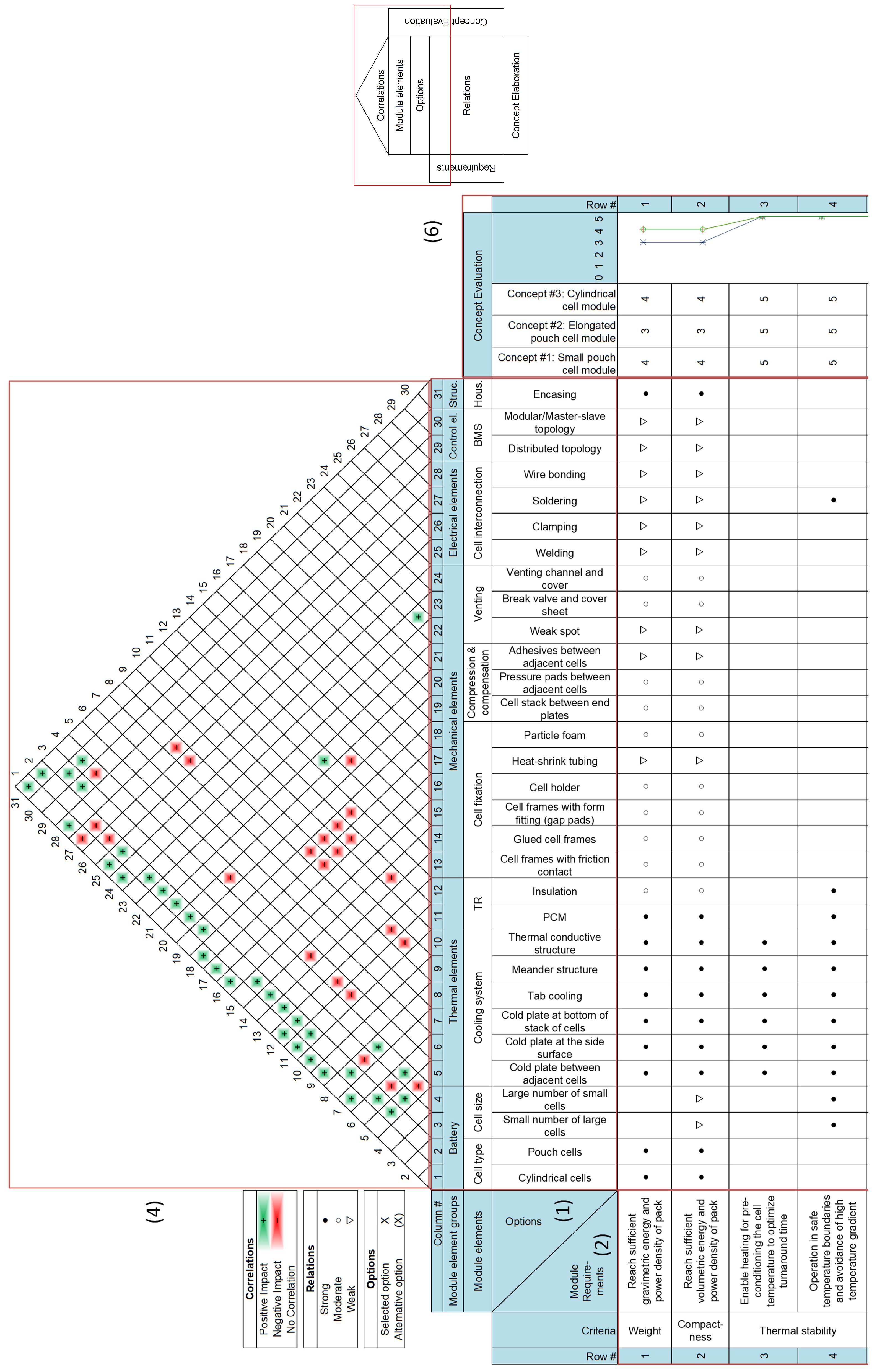
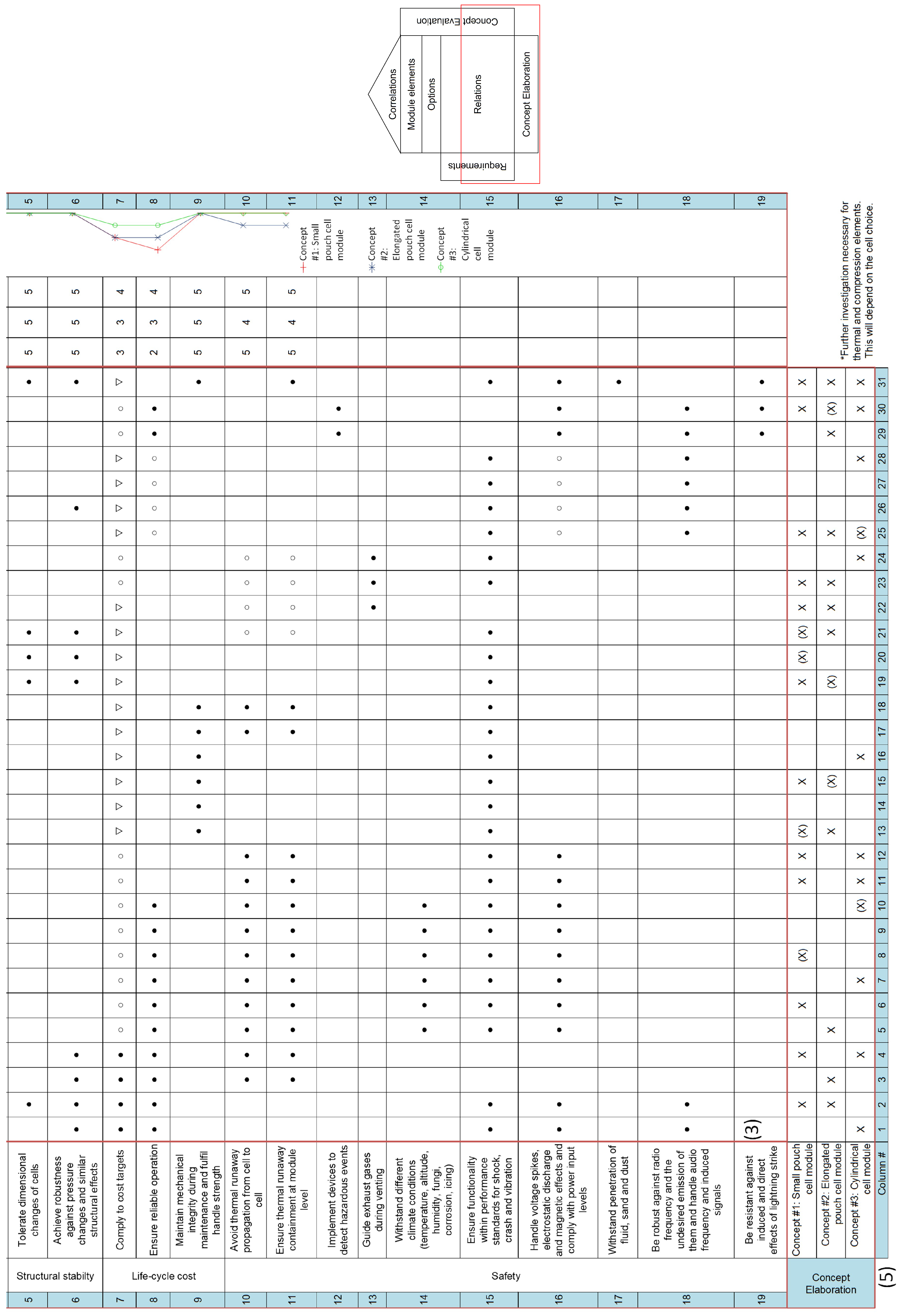
For the identification of promising module concepts, the HoQ is applied. It is an implementation of the quality function deployment and serves as a process to compare customer requirements with technical options to derive optimal and competitive solutions [31]. The resulting HoQ of this study is shown in Figure A1 of the appendix and compiles
- (1)
- The options of elements described in Section 2;
- (2)
- The requirements named in Section 2 and the criteria;
- (3)
- The relations between requirements and options;
- (4)
- The correlations between the options;
- (5)
- The concept elaboration of Section 4;
- (6)
- The concept evaluation of Section 5.
The following criteria are derived from the module requirements and must be respected during the selection of options for module elements in part (2) of the HoQ [9]:
- Weight: It is essential to consider the flight range and passenger capacity when determining a minimum energy and power density requirement. These specifications must be met, while respecting the maximum battery weight, considering the structural loading and strength of the aircraft.
- Compactness: Given the limited space of the aircraft, module elements must be densely packed, while maintaining a minimum cell-to-cell distance to prevent TR propagation.
- Thermal stability: Operation within a temperature range between 0 and 40 °C, as well as a temperature gradient below 5 °C, has to be adhered to.
- Structural stability: Adequate measures, such as compression and compensation for expanding pouch cells, have to be implemented, as well as robustness to pressure changes.
- Life-cycle cost: The production and maintenance costs as well as the reliability of the elements must be considered.
- Safety: The module design must respect the requirements for non-propagation and containment in case of TR according to the EASA [16] to avoid a chain reaction during operation and to guide the venting gases. Moreover, different environmental conditions must be respected [32].
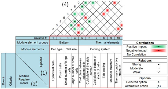
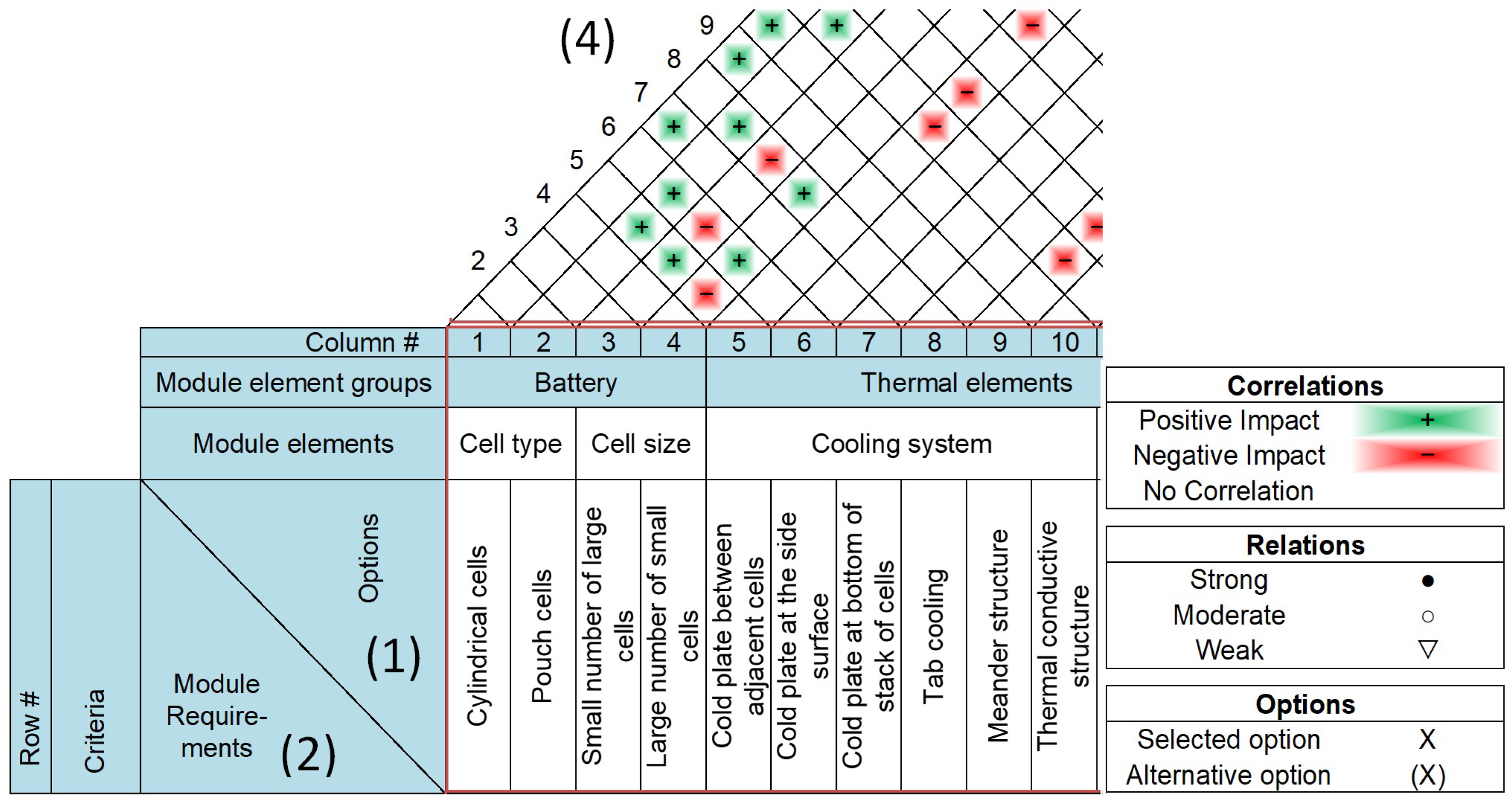
In the framework of this process, the relations between the requirements and the technical options are assessed in part (3) of the HoQ, as well as the correlations between the technical options themselves in part (4). For instance, the correlations between the battery and the cooling system are shown in Figure 1. It must be emphasised here that the cooling system is, in particular, dependent on the cell size, highlighted with specific colours in the figure. While surface cooling can result in a high number of cold plates for small pouch cells, side cooling can lead to a higher thermal gradient for elongated pouch cells. Tab cooling is an alternative for pouch cells, as the majority of the heat is concentrated in the tabs, but it is not appropriate for elongated pouch cells due to their high CCC. Moreover, the application of a TR strategy becomes more challenging for elongated pouch cells.
Figure 1.
Excerpt of the resulting HoQ of this study.
Based on the relations and correlations, the elaborated and evaluated concepts from part (5) and (6) of the HoQ will be described in the upcoming two sections.
4. Elaboration of Concepts
Three concepts are derived in part (5) of the HoQ, which are described below.
4.1. Small Pouch Cell Module (Concept 1) and Elongated Pouch Cell Module (Concept 2)
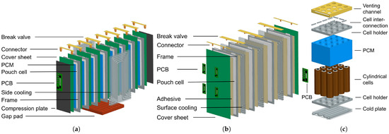
The designs of the pouch cell modules are shown in Figure 2a,b. The cells, or rather the cell frames, can be connected with glue or adhesives, resulting in a lightweight and compact design. In contrast, the use of gap pads would result in an easier disassembly process but can also reduce the distance between adjacent cells, as no adhesives or pressure pads are placed in between. The gap pads would also complicate the use of a cold plate or PCM between adjacent cells. In order to ensure structural stability in terms of compensation of the expansion of soft-packaged pouch cells, compression plates with flexible tie rods can be inserted at the end plates of the module, resulting in a compact design, while pressure pads and adhesives between adjacent cells are alternative options. The former option is the preferred choice in case of concept 1 to ensure direct contact between PCM and base area of the cells. Pressure pads are neglected for concept 2 so that the heat transfer of the cold plate does not deteriorate. One of the most preferred welding technologies is currently laser welding, where the tabs of two adjacent pouch cells can be welded. Alternative welding technologies have to be investigated in terms of process stability and joint characteristics. Although clinching may be applied to pouch cells to interlock two adjacent tabs, the structural integrity of the cells may be affected. Consequently, tab welding is currently the preferred choice for pouch cells [30]. Finally, a distributed BMS may be better suited for a small number of large cells. With decreasing cell size, the number of cells increases, leading to a greater coordination complexity between them. Despite the fact that wiring complexity will increase, the master–slave or modular topology seems to be the preferable choice for small cells [11].
Figure 2.
(a) Concept 1: small pouch cell module; (b) concept 2: elongated pouch cell module; (c) concept 3: small cylindrical cell module.
4.2. Cylindrical Cell Module (Concept 3)
In case of cylindrical cells, the design of the module is less dependent on the cell size compared to the pouch cell modules discussed in the previous sub-section. Therefore, a small-cell concept as shown in Figure 2c is favoured due to the reduced thermal gradients. A cell holder is the preferred choice for the cylindrical cell concept. While a heat-shrink tubing on the one hand would result in a reduced distance between cells, increasing the probability of TR propagation, the use of particle foam on the other hand would limit design options, particularly for the utilisation of PCM to mitigate TR. However, it may be possible to produce the cell holder from the material of the particle foam which demonstrates a lower density. The cooling system is based on a cold plate placed at the bottom of a cell stack, as the heat transfer in the axial direction is multiple times higher than in the radial direction for cylindrical cells [4]. Alternatively, the TCS and meander structure have demonstrated a reduction in the overall temperature and temperature gradient with a low weight ratio of the cooling system to the cells [13,14]. However, a combination of the meander structure with a PCM may be challenging as both of them require contact with the majority of the lateral area of the cells. A reasonable joining method for cylindrical cells besides laser welding is wire bonding, which has been chosen here due to its high technological maturity [30]. As for the small pouch cell module, a master–slave or modular topology seems to be the preferable choice, considering that concept 3 can result in a higher number of cells than shown in the exemplary design of Figure 2c.
5. Evaluation and Conclusions
The evaluation is conducted in part (6) of the HoQ. The results demonstrate that the small cylindrical cell module is the preferred option and outperforms the small pouch cell module with regard to reliability and life-cycle cost. Both of these concepts have a higher rating than the elongated pouch cell module in terms of TR strategy as well as module weight and compactness. It must be noted that the resulting chart of this work can be further expanded by taking more options into consideration, such as elements for humidity control or electrical elements like high-voltage connectors. A critical aspect for the preferred choice is the applicability of a hybrid cooling system as a proven successful measure against TR propagation. For the pouch cell, a hybrid cooling system may be more challenging due to the design complexity when including mechanical elements. Further analyses are required to understand the differences in temperature course, pressure drop, and weight of the cooling system. Therefore, the effectiveness of a hybrid cooling system must be investigated in subsequent work. Moreover, the HoQ elaborated in this study can serve as a baseline for future battery module design studies to enable short-range electric passenger flights and contribute to the aviation sustainability goals set by the ACARE.
Author Contributions
Conceptualisation, A.O.A., F.F. and S.K.; methodology, A.O.A.; formal analysis, A.O.A.; investigation, A.O.A.; writing—original draft preparation, A.O.A. and F.F.; writing—review and editing, A.O.A., F.F. and S.K.; visualisation, A.O.A.; supervision, F.F. and S.K.; project administration, A.O.A. and F.F.; funding acquisition, S.K. All authors have read and agreed to the published version of the manuscript.
Funding
This research received no external funding.
Institutional Review Board Statement
Not applicable.
Informed Consent Statement
Not applicable.
Data Availability Statement
A detailed explanation of the results can be made available on request.
Conflicts of Interest
The authors declare no conflicts of interest.
Abbreviations
The following abbreviations are used in this manuscript:
| AEA | All-Electric Aircraft |
| BMS | Battery management system |
| CCC | Cell cooling coefficient |
| EASA | European Union Aviation Safety Agency |
| HoQ | House of quality |
| PCM | Phase-change material |
| TCS | Thermal conductive structure |
| TR | Thermal runaway |
Appendix A
Figure A1.
Exemplary house of quality of this study considering (1) the options of elements described in Section 2, (2) the requirements named in Section 2 and the criteria, (3) the relations between requirements and options, (4) the correlations between the options, (5) the concept elaboration of Section 4 and (6) the concept evaluation of Section 5.
References
- ACARE. Strategic Research and Innovation Agenda. Available online: https://open4aviation.at/resources/pdf/ACARE-Strategic-Research-Innovation-Volume-1.pdf (accessed on 24 June 2025).
- de Vries, R.; Wolleswinkel, R.E.; Rosen Jacobsen, D.; Bonnema, G.M.; Thiede, S. Battery Performance Metrics for Large Electric Passenger Aircraft. In Proceedings of the 34th Congress of the International Council of Aeronautical Sciences, Florence, Italy, 9–13 September 2024. [Google Scholar]
- Arora, S.; Kapoor, A. Mechanical Design and Packaging of Battery Packs for Electric Vehicles. In Behaviour of Lithium-Ion Batteries in Electric Vehicles; Pistoia, G., Liaw, B., Eds.; Springer: Cham, Switzerland, 2018; pp. 175–200. [Google Scholar]
- Altun, A.O.; Franke, F.; Kazula, S. Overview of the State of the Art in Battery Packaging and Elaboration of a Safe Design Process for Battery Packs in Large Electric Aircraft. In Proceedings of the Deutscher Luft- und Raumfahrtkongress 2024, Hamburg, Germany, 30 September–2 October 2024. [Google Scholar] [CrossRef]
- Michaelis, S.; Schütrumpf, J.; Kampker, A.; Heimes, H.; Dorn, B.; Wennemar, S.; Scheibe, A.; Wolf, S.; Smulka, M.; Ingendoh, B.; et al. Roadmap Battery Production Equipment 2030. Technical Report, VDMA Battery Production, 2023. Available online: https://vdma-branchenfuehrer.de/fileadmin/battprod/downloads/VDMA_Batterieproduktion_Roadmap_2023_EN__1_.pdf (accessed on 24 July 2025).
- Stefan, I. Silicon Enabled Energy Storage with Extreme Energy and Power Density. Available online: https://www.nasa.gov/wp-content/uploads/2024/01/amprius-technologies-for-nasa-2023.pdf (accessed on 24 June 2025).
- Peng, Y.; Zhou, X.; Hu, Y.; Ju, X.; Liao, B.; Yang, L. A new exploration of the fire behaviors of large format lithium ion battery. J. Therm. Anal. Calorim. 2020, 139, 1243–1254. [Google Scholar] [CrossRef] [Scilit]
- Pesaran, A.A.; Kim, G.H.; Keyser, M. Integration Issues of Cells into Battery Packs for Plug-in and Hybrid Electric Vehicles. In Proceedings of the EVS-24 International Battery, Hybrid and Fuel Cell Electric Vehicle Symposium, Stavanger, Norway, 13–16 May 2009. [Google Scholar]
- Arora, S.; Kapoor, A.; Shen, W. Application of Robust Design Methodology to Battery Packs for Electric Vehicles: Identification of Critical Technical Requirements for Modular Architecture. Batteries 2018, 4, 30. [Google Scholar] [CrossRef] [Scilit]
- Rothgang, S.; Baumhöfer, T.; van Hoek, H.; Lange, T.; de Doncker, R.W.; Sauer, D.U. Modular battery design for reliable, flexible and multi-technology energy storage systems. Appl. Energy 2015, 137, 931–937. [Google Scholar] [CrossRef] [Scilit]
- Andrea, D. Lithium-Ion Batteries and Applications: A Practical and Comprehensive Guide to Lithium-Ion Batteries and Arrays, from Toys to Towns, Volume 1, Batteries; Artech House: Norwood, MA, USA, 2020. [Google Scholar]
- Weng, J.; Ouyang, D.; Yang, X.; Chen, M.; Zhang, G.; Wang, J. Alleviation of thermal runaway propagation in thermal management modules using aerogel felt coupled with flame-retarded phase change material. Energy Convers. Manag. 2019, 200, 112071. [Google Scholar] [CrossRef] [Scilit]
- Zhao, J.; Du, W.; Xiang, H.; Gu, L. Heat transfer characteristics of liquid cooling system for lithium-ion battery pack. Proc. Inst. Mech. Eng. D 2025, 239, 1108–1121. [Google Scholar] [CrossRef] [Scilit]
- Lai, Y.; Wu, W.; Chen, K.; Wang, S.; Xin, C. A compact and lightweight liquid-cooled thermal management solution for cylindrical lithium-ion power battery pack. Int. J. Heat Mass Transf. 2019, 144, 118581. [Google Scholar] [CrossRef] [Scilit]
- Dondelewski, O.; Szemberg O’Connor, T.; Zhao, Y.; Hunt, I.A.; Holland, A.; Hales, A.; Offer, G.J.; Patel, Y. The role of cell geometry when selecting tab or surface cooling to minimise cell degradation. eTransportation 2020, 5, 100073. [Google Scholar] [CrossRef] [Scilit]
- European Union Aviation Safety Agency (EASA). Third Publication of Proposed Means of Compliance with the Special Condition VTOL. Available online: https://www.easa.europa.eu/sites/default/files/dfu/MOC-3_SC-VTOL_-_Issue_2_-_21_Jun_2023_-_FINAL.pdf (accessed on 24 June 2025).
- A123 Energy Solutions. Battery Pack Design, Validation, and Assembly Guide using A123 Systems AMP20 M1 HD-A Nanosphate Cells. Available online: https://www.buya123products.com/uploads/vipcase/b24d4f5b63934c59d43e93b3bb4db60a.pdf (accessed on 24 June 2025).
- Vetterlein, A.; Franke, F.; Kazula, S. Review and Evaluation of Strategies for Mitigation of Degradation and Failure Effects of Batteries in Electric Aircraft Propulsion. In Proceedings of the Deutscher Luft- und Raumfahrtkongress 2025, Augsburg, Germany, 23–25 September 2025. in print. [Google Scholar]
- Zhao, L.; Song, G.; Yang, X.; Pan, R. Experiments on the effects of liquid immersion cooling on the thermal runaway (TR) behaviors of 280 Ah lithium-ion batteries subjected to different TR-triggering conditions. J. Energy Storage 2025, 121, 116358. [Google Scholar] [CrossRef] [Scilit]
- Zhang, W.; Liang, Z.; Yin, X.; Ling, G. Avoiding thermal runaway propagation of lithium-ion battery modules by using hybrid phase change material and liquid cooling. Appl. Therm. Eng. 2021, 184, 116380. [Google Scholar] [CrossRef] [Scilit]
- Aiello, L.; Hanzu, I.; Gstrein, G.; Ewert, E.; Ellersdorfer, C.; Sinz, W. Analysis and Investigation of Thermal Runaway Propagation for a Mechanically Constrained Lithium-Ion Pouch Cell Module. Batteries 2021, 7, 49. [Google Scholar] [CrossRef] [Scilit]
- Kampker, A.; Wessel, S.; Fiedler, F.; Maltoni, F. Battery pack remanufacturing process up to cell level with sorting and repurposing of battery cells. J. Remanuf. 2021, 11, 1–23. [Google Scholar] [CrossRef] [Scilit]
- AsahiKASEI. Technischer Partikelschaum SunForce. Available online: https://www.asahi-kasei-plastics.com/de/products/sunforce/ (accessed on 15 June 2025).
- Scott, S.; Islam, Z.; Allen, J.; Yingnakorn, T.; Alflakian, A.; Hathaway, J.; Rastegarpanah, A.; Harper, G.D.J.; Kendrick, E.; Anderson, P.A.; et al. Designing lithium-ion batteries for recycle: The role of adhesives. Next Energy 2023, 1, 100023. [Google Scholar] [CrossRef] [Scilit]
- da Silva, L.F.M.; Öchsner, A.; Adams, R.D. Introduction to Adhesion Technology. In Handbook of Adhesion Technology; da Silva, L.F.M., Öchsner, A., Adams, R.D., Eds.; Springer: Cham, Switzerland, 2018; pp. 1–7. [Google Scholar] [CrossRef] [Scilit]
- Aufschläger, A.; Durdel, A.; Kraft, L.; Jossen, A. Optimizing mechanical compression for cycle life and irreversible swelling of high energy and high power lithium-ion pouch cells. J. Energy Storage 2024, 76, 109883. [Google Scholar] [CrossRef] [Scilit]
- Dai, F.; Cai, M. Best practices in lithium battery cell preparation and evaluation. Commun. Mater. 2022, 3, 64. [Google Scholar] [CrossRef] [Scilit]
- Link, S.; Neef, C.; Wicke, T.; Hettesheimer, T.; Diehl, M.; Krätzig, O.; Degen, F.; Klein, F.; Fanz, P.; Burgard, M.; et al. Development Perspectives for Lithium-Ion Battery Cell Formats. Technical Report, Fraunhofer Institute for Systems and Innovation Research ISI, 2022. Available online: https://www.isi.fraunhofer.de/content/dam/isi/dokumente/cct/2022/Development_perspectives_for_lithium-ion_battery_cell_formats_Fraunhofer_2022.pdf (accessed on 3 April 2025).
- John, L.S.; De Keyser, H.; Dekeyser, A.; Berg, L.F.; Tübke, J.; Doppelbauer, M. Fire protection design concepts in a composite battery module housing. In Proceedings of the 16th International Symposium and Exhibition on Sophisticated Car Safety Systems (Airbag 2024), Mannheim, Germany, 25–27 November 2024. [Google Scholar] [CrossRef]
- Das, A.; Li, D.; Williams, D.; Greenwood, D. Joining Technologies for Automotive Battery Systems Manufacturing. World Electr. Veh. J. 2018, 9, 22. [Google Scholar] [CrossRef] [Scilit]
- Hauser, J.; Clausing, D. The House of Quality. In Harvard Business Review; Springer: Berlin/Heidelberg, Germany, 1988. [Google Scholar]
- Radio Technical Commission for Aeronautics Environmental (RTCA). Environmental Conditions and Test Procedures for Airborne Equipment; DO-160G: Washington DC, USA, 2010. [Google Scholar]
Disclaimer/Publisher’s Note: The statements, opinions and data contained in all publications are solely those of the individual author(s) and contributor(s) and not of MDPI and/or the editor(s). MDPI and/or the editor(s) disclaim responsibility for any injury to people or property resulting from any ideas, methods, instructions or products referred to in the content. |
© 2026 by the authors. Licensee MDPI, Basel, Switzerland. This article is an open access article distributed under the terms and conditions of the Creative Commons Attribution (CC BY) license.