Proceeding Paper

Overall Design and Technology Integration for a Nine-Seater Hydrogen-Electric Commuter Aircraft Concept †
1
Institute of System Architectures in Aeronautics, German Aerospace Center (DLR), Hein-Saß-Weg 22, 21129 Hamburg, Germany
2
Institute of Electrified Aero Engines, German Aerospace Center (DLR), Lieberoser Straße 13a, 03046 Cottbus, Germany
*
Author to whom correspondence should be addressed.
Presented at the 15th EASN International Conference, Madrid, Spain, 14–17 October 2025.
Eng. Proc. 2026, 133(1), 19; https://doi.org/10.3390/engproc2026133019
Published: 20 April 2026

Abstract

New propulsion technologies not only allow reducing the climate effect of aircraft, but also enable new architectures and integration options. To make use of this increased design space variety, new design methods need to be developed. In this work, an existing design process for CS-23 hydrogen-electric aircraft is expanded with the capability to design various powertrain options. These methods are used to evaluate the designs of two different concepts for small commuter aircraft with centralized and distributed fuel cell (FC) systems, respectively. The results show that the overall mass and performance of both concepts are very similar. However, the concept with distributed FC systems has a lower energy consumption, better FC cooling, and improved maintainability. Thus, the distributed concept is chosen. The final design has the powertrain components distributed among 10 engine pods. To transport nine passengers over 600 km without exceeding the targeted Maximum Take-off Mass (MTOM) of 5700 kg, the propulsion system’s power-to-weight ratio needs to be improved by 1.2% from the current technology level.

1. Introduction

One of the biggest challenges of the global aviation industry is the reduction in the climate effect of air traffic. Due to the continuously growing demand for flexible and fast mobility, it is necessary to drastically reduce the negative effects on airplane level [1]. New propulsion technologies, such as hydrogen-electric propulsion, could enable significant improvements in efficiency and emissions. However, the financial and technological risks for introducing such technologies in large CS-25 aircraft are considerable, as shown by the delay of the Airbus ZEROe program [2]. In contrast, smaller aircraft in the CS-23 category are more suitable for implementing novel technologies, because of the less strict certification requirements [3,4] and the smaller scale, both of which reduce costs and complexity.
To evaluate a possible application of a hydrogen-electric powertrain, a nine-seater commuter aircraft is designed and analyzed. Based on an existing design [5], the concept is refined and additional disciplines are taken into account in greater detail. The focus lies on the integration of the powertrain components and the hydrogen tanks, primarily considering the aspects of performance and safety.

2. Overall Design

As a starting point, the “D-Light” aircraft design is used [5]. Changes to the propulsion system are made, specifically the fuel cell type and tank integration.

2.1. Requirements

The design is aimed at a typical commuter role, i.e., flights between small regional airports or from smaller to larger airports. The Top-Level Aircraft Requirements (TLARs), such as Take-off Field Length (TOFL), reflect the intended use case and are mostly identical to the initial concept [5]. The selected values are shown in Table 1.

2.2. Configuration

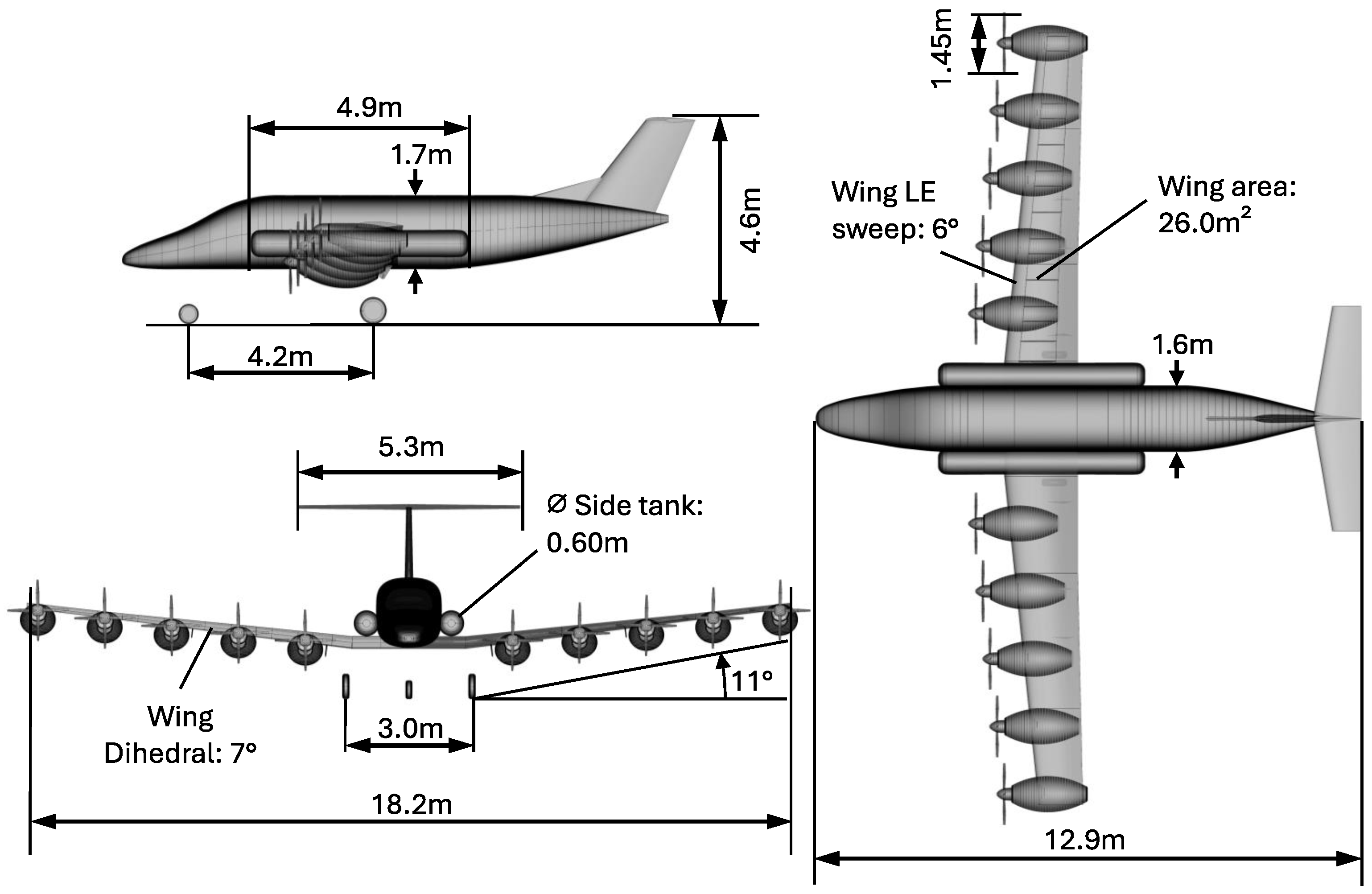
The overall aircraft configuration is generally unchanged from the initial concept [5]. A conventional tube-and-wing configuration is used with a low-mounted wing. A Distributed Electric Propulsion (DEP) system is used, which consists of 10 engine pods mounted under the wing. The overall configuration is illustrated in Figure 1.

2.3. Propulsion System

In the initial concept, an air-cooled Proton Exchange Membrane (PEM) fuel cell system was used. The reason for that design choice was to reduce complexity, thus reducing cost and improving maintainability [5]. However, the air-cooled fuel cell technology is currently not sufficiently mature to be entered into service. To be operated in transport aircraft, the technology needs to be significantly upscaled and undergo expansive demonstration and certification processes.
Therefore, a liquid-cooled PEM fuel cell system will be used instead. This technology is already demonstrated as a propulsion system in-flight [9]. The liquid cooling system enables separating the fuel cell stack and the cooling system. Thus, new propulsion architectures and integration options are possible. The design methods and decision process for the propulsion architecture and integration are further described in Section 3 and Section 4.

2.4. Hydrogen Tank Integration

For hydrogen storage, a pressure tank with 700 bar is used. While the structural efficiency of a pressure tank is lower compared to cryogenic tanks, the complexity of the on-board systems and of the ground infrastructure is much lower. Due to the operation from smaller airports with limited ground infrastructure, reducing complexity is given a higher priority.
In the previous concept, the tanks were placed above the cabin [5]. However, further investigations regarding crash safety showed that heavy tanks above the cabin can compromise its structural integrity in case of a crash with vertical loads and pose a significant danger to the passengers. Thus, a new integration concept is selected.
Following an evaluation of different concepts, two tanks located to the side of the fuselage directly above the wing root are chosen. As they are outside of the cabin, the tanks offer good safety and are favorable in terms of structural integration and Center of Gravity (COG). The tank integration is also shown in Figure 1.

2.5. Technology Factors

The tools used in the aircraft design process, described in more detail later in Section 3.1, are based on existing technology and aircraft. Technology factors are utilized to include expected improvements for some disciplines and to enable the design to meet the TLARs.
The following assumptions are therefore applied:
  • The hydrogen tank mass is reduced by 10%. This is justified by available carbon fibers with an 18% higher tensile strength compared to the fibers used in the tank sizing tool [10].
  • The masses of the airframe components—fuselage, wing and tail—are reduced by 20%. This is due to the fact that most existing commuter aircraft designs date back to the 1960s and 70s, and further improvements can be expected with better calculation methods and the use of Carbon Fiber-Reinforced Polymer (CFRP).
  • The drag increase due to the cooling drag of the fuel cell system is estimated based on the Computational Fluid Dynamics (CFD) results of comparable configurations [11]. The drag forces are scaled with respect to heat flow, cruise speed, and reference area. For the centralized fuel cell system, a drag increase of 90 drag counts is assumed. For the distributed fuel cell system, an increase of 10% of the viscous drag component is used.
  • The fulfillment of the 5700 kg MTOM limit is critical and largely depends on the powertrain mass. Therefore, the mass of the fuel cell system and electric motor are adjusted such that the MTOM limit is met. The required powertrain mass reduction factor is a result of the design process and is used as an evaluation metric.

3. Powertrain Integration

The hydrogen-electric powertrain is the most important innovation of this aircraft concept. Due to its significance in both propulsion efficiency and mass contribution, it has a high impact on aircraft performance. Therefore, it is necessary to consider its integration into the overall aircraft with a high level of detail.

3.1. Design Methods

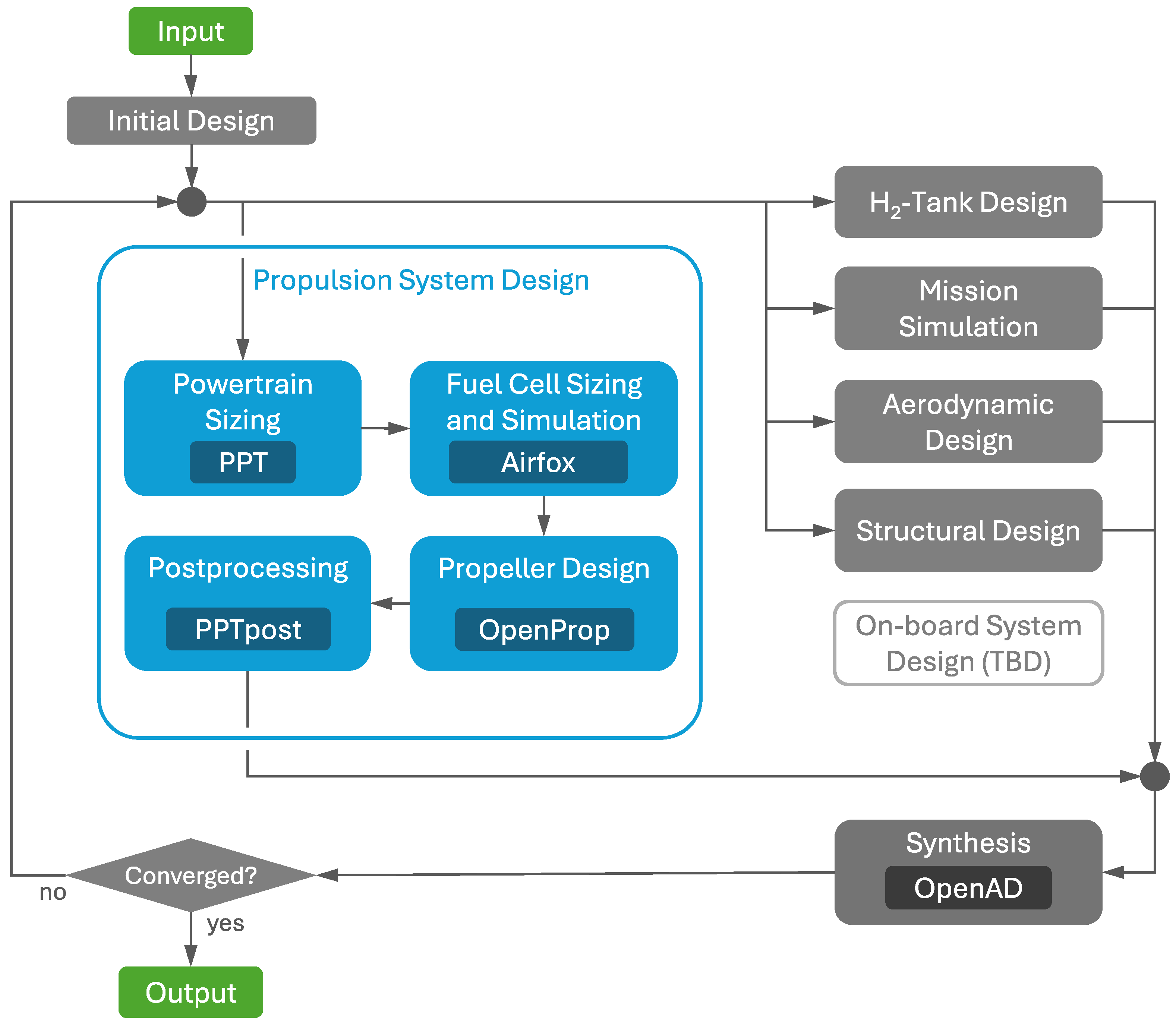
Based on the methods introduced in the D-Light project [5], existing tools are refined and new tools are included. The design process is fully automated, which allows the flexibility to quickly design and evaluate different configurations. An overview of the design workflow is shown in Figure 2.
For the design of the propulsion system, the following tools are used:
  • The Python Powertrain Tool is based on the method and models described in [12,13,14] and is used for the components responsible for producing propeller shaft power from electric DC power. It takes the whole mission shaft power requirements as well as environmental conditions into account, sizes the components, and handles the operating strategy by calculating the electric power demand for the fuel cell system or batteries in each step. Furthermore, it includes a thermal management system for its components as well as the battery sizing. Version 0.6 was used.
  • Airfox [15] is used to design and size the FC system and to simulate its performance over the entire envelope. Its capability includes the design of air-cooled open-cathode, air-cooled closed-cathode, and liquid-cooled FC systems. The underlying models are obtained from experimental testing of commercially available fuel cell stacks. The additional FC system components, such as the heat exchanger, compressor, humidifier, and cooling system, are sized from balance of plant requirements. Version 0.2 was used.
  • OpenProp [16] is used to simulate the propeller. The tool reads the propeller geometry from the overall design and simulates the propeller performance using blade-element momentum theory in the design point and for off-design phases. Version 2.0 was used.

3.2. Powertrain Architecture

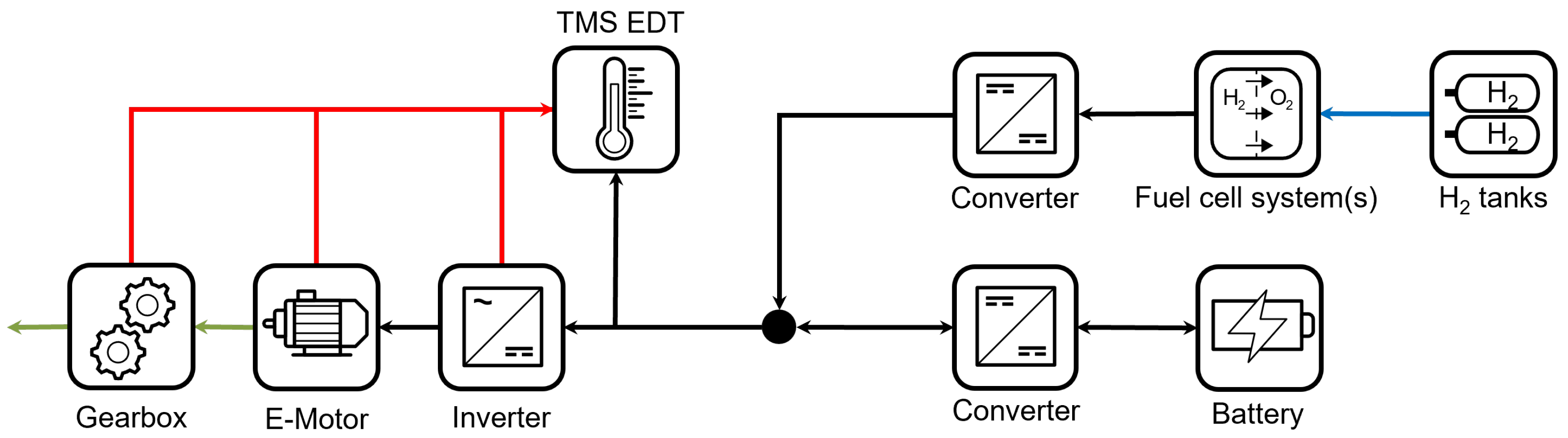
The basic powertrain architecture that is modeled by these tools is shown in Figure 3. A single-stage gearbox with a fixed transmission ratio of 1:5 is used to increase the shaft rotational speed of 2250 rpm at the propeller and decrease the required torque from the motor to allow for a more lightweight motor design. The gearbox, motor, and inverter are liquid-cooled via a shared thermal management system (TMS). Electric direct-current power at system voltage level is provided from the fuel cell system(s) or batteries, depending on the degree of hybridization.

3.3. Integration Concepts

Keeping in line with the overall configuration and TLARs, two main integration concepts are analyzed. The gearbox, inverter, and propeller are in each nacelle for both concepts. The main difference is the number and location of the FC systems:
  • Ten smaller FC systems distributed among all nacelles.
  • Two large FC systems integrated within the rear fuselage (for redundancy, at least two independent FC systems are necessary).
These concepts are implemented in the design process, taking into account the impact on disciplines, such as mass and mass distribution, systems architecture, aerodynamics, and structure. However, not all effects can currently be represented with the design methods. For example, the aerodynamic interactions between the propeller slipstream and the cooling system are too complex to be modeled with a sufficient level of detail at the preliminary design stage. Therefore, assumptions have to be made for several aspects.

4. Results

To find the most suitable powertrain architecture and integration concept, the results of the design process, as well as the qualitative aspects of both integration concepts, are evaluated.

4.1. Powertrain Architecture Selection

An overview of the design results is given in Table 2.
The results show that the overall results are very similar for both concepts. The difference of the powertrain mass reduction factor is 1.2 percentage points, which certainly lies within the accuracy of the design methods. A notable difference is that the distributed concept has a higher FC system mass, which is attributed to the negative scaling effects of using 10 individual FC systems. On the other hand, the centralized concept has a higher mission fuel mass, thus increasing energy consumption and consequently requiring heavier H 2 tanks. This is due to the increased drag of the FC cooling system.
In addition to the design results, a qualitative analysis of the two concepts was done. The integration of the centralized concept is facilitated by the large amount of space available in the rear fuselage and results in much smaller pods. On the other hand, the distributed concept has several advantages, mainly improved cooling performance due to the propeller slipstream. The accessibility and maintainability are improved due to pod integration (the distributed concept allows the exchange of the entire pod for maintenance, similar to the procedure for turbofan engines). Furthermore, on a broader scope, the propulsion system is more modular. By varying the number of pods, it can be flexibly applied to larger or smaller aircraft without the need to redesign the engine pods.
Overall, the quantitative and qualitative results indicate that the distributed concept is favorable on the overall aircraft level for this type of aircraft.

4.2. Final Design

Using the design process, the final design with the selected propulsion architecture is generated. Figure 4 shows the overall geometry and important dimensions. Notably, the powertrain integration in the nacelles results in large engine pods. To store the required fuel, voluminous H 2 tanks are required. The H 2 tank integration on the side of the fuselage limits the space available for windows and exits. As a consequence, the exit door and emergency exit have the minimum required size and are located in the very back of the fuselage. Important powertrain properties and overall performance are listed in Table 3.
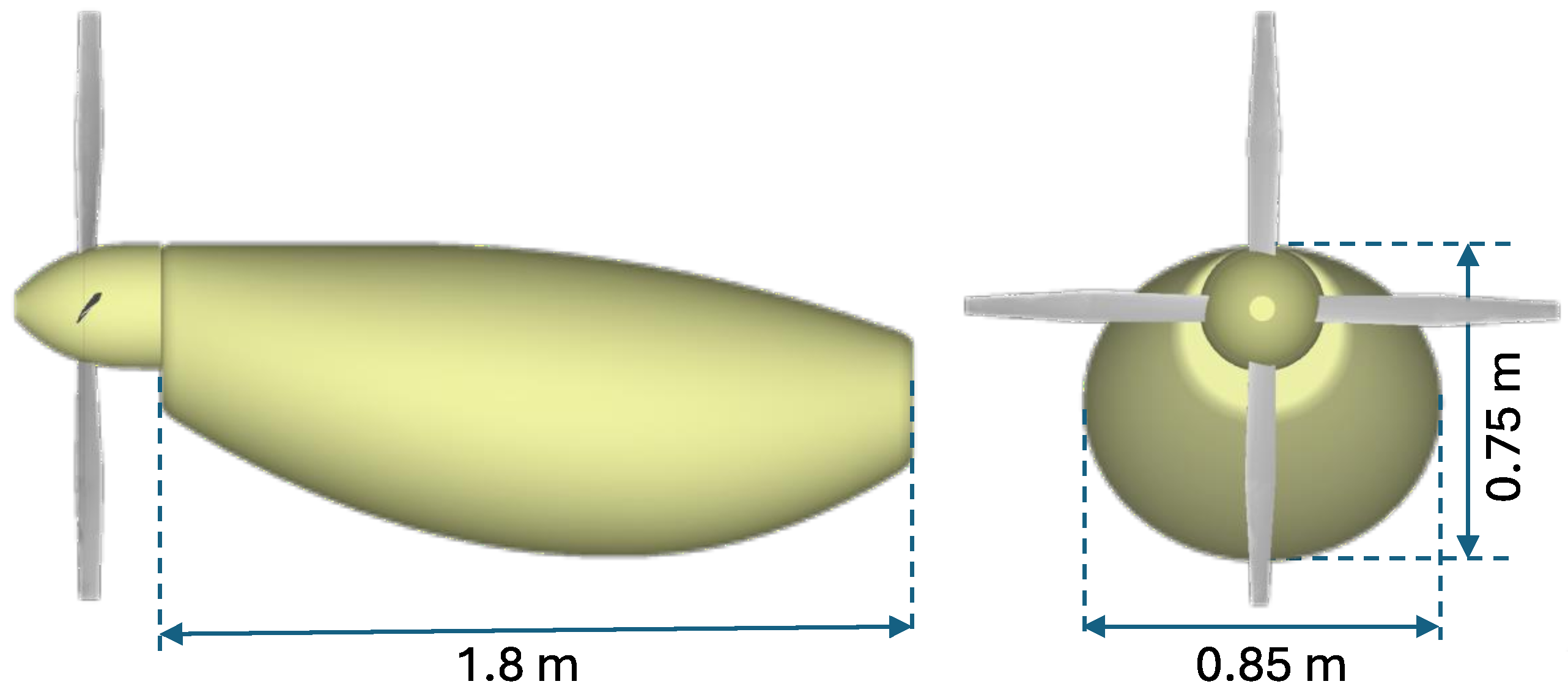
Because almost all powertrain components are distributed among the engine pods, the component masses and integration into the pod are critical design results. The FC system including TMS has the largest impact, contributing almost 2/3 of the total mass; see Table 4. The packaging of the components within the pod is not performed in the current state of the design process. Therefore, the pod is sized preliminarily by estimating internal geometry and the component arrangement. The resulting pod dimensions are shown in Figure 5.

5. Discussion

The presented results suggest that a hydrogen-powered nine-seater commuter aircraft is generally feasible. At the considered detail level and with the assumed technology factors, the targeted mission performance can be achieved. The heavy powertrain and H 2 tank significantly contribute to the overall mass. To keep the MTOM below the imposed limit of 5700 kg, minor mass reductions are still necessary. Improving the power-to-weight ratio of the propulsion system by 1–2% is sufficient, which is considered to be feasible until the EIS.
The evaluation of different powertrain architectures shows that the overall mass of both distributed and centralized FC system integration concepts is similar. The major difference is in fuel consumption, with the distributed concept requiring a 15% lower mission fuel mass. In terms of qualitative considerations, the distributed concept shows further advantages, such as cooling performance, maintenance, or transferability to other aircraft configurations. Consequently, the distributed concept is selected.
Although many dependencies and interactions are represented in the design methods, some gaps with potentially significant impacts on the overall results were identified. Most importantly, to understand the effect of the propeller slipstream on aerodynamics and cooling performance, more detailed investigations are required. This also includes the effect of the engine pods on the overall lift distribution. The cooling system performance is particularly relevant in high temperatures and flight phases with high power demand, such as a go-around. These aspects will be focused on in the further course of this work, improving the accuracy and certainty of the design methods and enabling a more dependable conceptual design.

Author Contributions

Conceptualization: S.K.-G.; methodology: S.K.-G. and J.L.; software: S.K.-G. and J.L.; validation: S.K.-G. and J.L.; formal analysis: S.K.-G. and I.Z.; writing—original draft preparation: S.K.-G.; writing—review and editing: all; supervision: T.Z.; project administration: S.K.-G. All authors have read and agreed to the published version of the manuscript.

Funding

This research received no external funding.

Institutional Review Board Statement

Not applicable.

Informed Consent Statement

Not applicable.

Data Availability Statement

The datasets presented in this article are not readily available because they are part of an ongoing study. Requests to access the datasets should be directed to the corresponding author.

Conflicts of Interest

The authors declare no conflicts of interest.

Abbreviations

The following abbreviations are used in this manuscript:
A/CAircraftICAOInternational Civil Aviation Organization
CFDComputational Fluid DynamicsISAStandard Atmosphere Conditions
CFRPCarbon Fiber-Reinforced PolymerLFLLanding Field Length
CoGCenter of GravityMTOMMaximum Take-Off Mass
CSCertification SpecificationOEMOperating Empty Mass
DEPDistributed Electric PropulsionPEMProton Exchange Membrane
DLRGerman Aerospace CenterTASTrue Airspeed
EASAEuropean Aviation Safety AgencyTLARsTop-Level Aircraft Requirements
EISEntry into ServiceTMSThermal Management System
FCFuel CellTOFLTake-off Field Length

References

  1. ICAO. 2025 Environmental Report; ICAO: Montréal, QC, Canada, 2025. [Google Scholar]
  2. Tim Hepher. Airbus Postpones Development of New Hydrogen Aircraft. Available online: https://www.reuters.com/business/aerospace-defense/airbus-postpones-development-new-hydrogen-aircraft-2025-02-07/ (accessed on 11 November 2025).
  3. EASA. Certification Specifications for Normal-Category Aeroplanes: CS-23Amendment 6; EASA: Cologne, Germany, 2023. [Google Scholar]
  4. EASA. The New CS-23–Smart and Flexible Rules that Support Innovation. Available online: https://easa.europa.eu/en/domains/general-aviation/general-aviation-road-map/new-cs-23-%E2%80%93-smart-and-flexible-rules-support-innovation (accessed on 11 November 2025).
  5. Kolb-Geßmann, S.; Atanasov, G.; Zill, T. Conceptual Design of a Hydrogen-Powered 9-Seater Commuter Aircraft. In Proceedings of the Deutscher Luft- und Raumfahrtkongress; Deutsche Gesellschaft für Luft- und Raumfahrt—Lilienthal-Oberth e.V.: Bonn, Germany, 2023. [Google Scholar] [CrossRef]
  6. Will, F.; Flüthmann, N.; Eschmann, C. Derivation of Top-Level Aircraft Requirements for Small Aircraft Transport by Modelling Demand in Europe. IOP Conf. Ser. Mater. Sci. Eng. 2022, 1226, 012091. [Google Scholar] [CrossRef] [Scilit]
  7. DFS Deutsche Flugsicherung. Luftfahrthandbuch Deutschland VFR. Available online: https://aip.dfs.de/BasicVFR/pages/C00001.html (accessed on 11 November 2025).
  8. ICAO. Annex 14 to the Convention on International Civil Aviation: Aerodromes—Volume 1: Aerodrome Design and Operations; ICAO: Montréal, QC, Canada, 2018. [Google Scholar]
  9. Rathke, P.; Kallo, J.; Schirmer, J.; Stephan, T.; Waiblinger, W.; Weiss-Ungethüm, J. Antares DLR-H2—Flying Test Bed for Development of Aircraft Fuel Cell Systems. ECS Trans. 2013, 51, 229–241. [Google Scholar] [CrossRef] [Scilit]
  10. Cui, Y.; Yin, Z. Size Effect on the Mechanical Properties of CF Winding Composite. IOP Conf. Ser. Mater. Sci. Eng. 2017, 274, 012021. [Google Scholar] [CrossRef] [Scilit]
  11. Kirz, J.; Hübner, A.R.; Spinner, S. Systematic Numerical Investigations of Heat Exchangers integrated behind Propellers of Hybrid-Electric Propulsion Aircraft Configurations. In Deutscher Luft- und Raumfahrtkongress; Deutsche Gesellschaft für Luft- und Raumfahrt—Lilienthal-Oberth e.V.: Bonn, Germany, 2023. [Google Scholar] [CrossRef]
  12. Ludowicy, J.; Bahrs, V.J.; Staggat, M. Feasibility study for a medium-range regional aircraft retrofit with battery powered propulsion system. In Proceedings of the Aerospace Europe Conference 2023—10th EUCASS–9th CEAS; EUCASS: Bruxelles, Belgium, 2023. [Google Scholar] [CrossRef]
  13. Bahrs, V.J.; Staggat, M.; Enghardt, L. Analytical model for electric machine sizing in electrified aviation. In Proceedings of the Deutscher Luft- und Raumfahrtkongress 2022; Deutsche Gesellschaft für Luft- und Raumfahrt—Lilienthal-Oberth e.V.: Bonn, Germany, 2022. [Google Scholar] [CrossRef]
  14. Link, A.; Staggat, M.; de Graaf, S. Characterisation of thermal management system specific heat rejection for electric propulsion architectures. In Proceedings of the Aerospace Europe Conference 2023—10th EUCASS—9th CEAS; EUCASS: Bruxelles, Belgium, 2023. [Google Scholar] [CrossRef]
  15. Schröder, M.; Albrecht, P.; Juschus, D.; Fischer, S.; Gentner, C. Fuel cell system design and optimization: The airfox tool. In Proceedings of the Architecting Future Aviation, Hamburg, Germany, 1–2 April 2025; Available online: https://elib.dlr.de/213448 (accessed on 28 November 2025).
  16. Atanasov, G.; Wehrspohn, J.; Kühlen, M.; Cabac, Y.; Silberhorn, D.; Kotzem, M.; Dahlmann, K.; Linke, F. Short-Medium-Range Turboprop-Powered Aircraft as a Cost-Efficient Enabler for Low Climate Impact. In Proceedings of the AIAA Aviation; AIAA: Reston, VA, USA, 2023. [Google Scholar] [CrossRef] [Scilit]
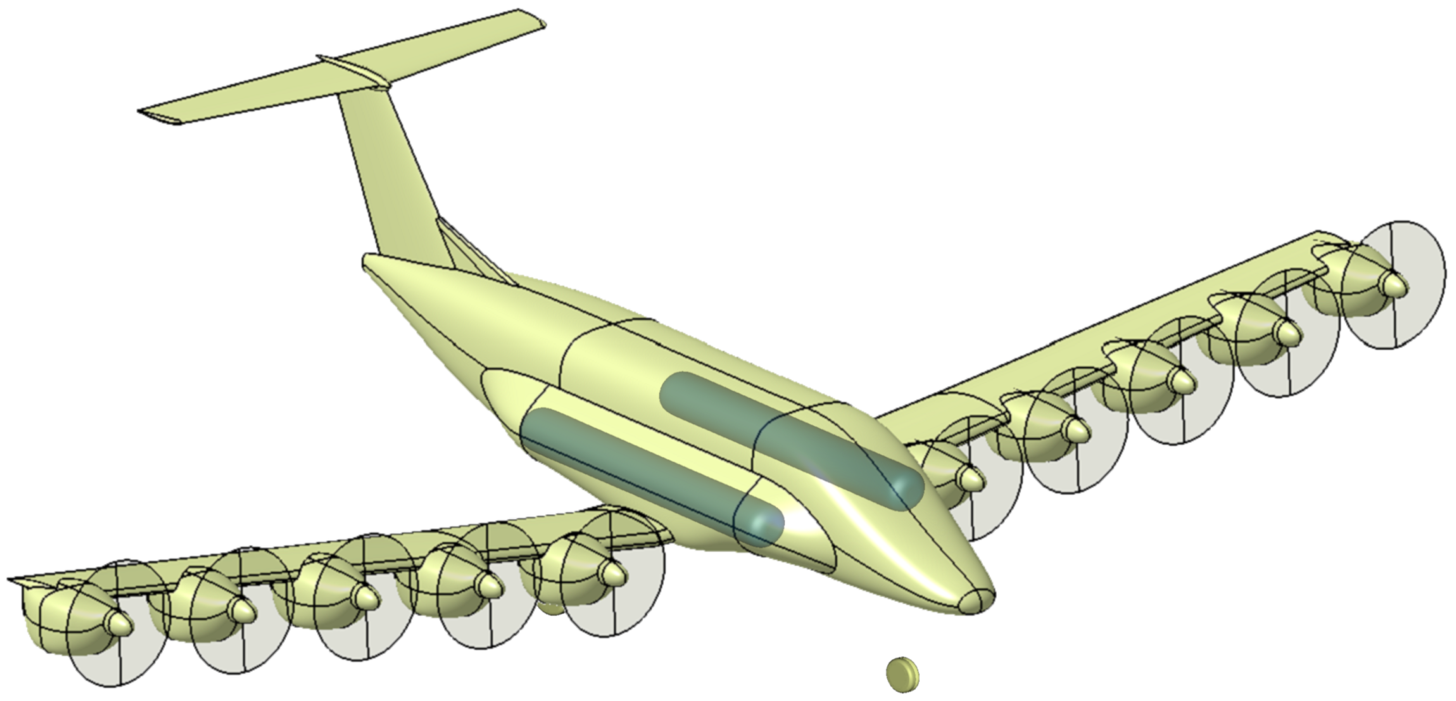
Figure 1. Visualization of the overall aircraft configuration and the tank integration concept.
Engproc 133 00019 g001
Figure 2. Overall structure of the design workflow. The propulsion system design subprocess is highlighted.
Engproc 133 00019 g002
Figure 3. Powertrain architecture overview. Blue lines: hydrogen; Black lines: electrical energy; Red lines: thermal energy; Green lines: mechanical energy.
Engproc 133 00019 g003
Figure 4. Dimensions of the overall aircraft, not showing the H 2 tank fairings and wing fairing.
Engproc 133 00019 g004
Figure 5. Dimensions of engine pod (pod shape is not representative).
Engproc 133 00019 g005
Table 1. TLARs and criteria.
TLARValueComment
Passengers9Project requirement
Design payload855 kg95 kg per pax
Design range600 kmMarket analysis, demand model [6]
Cruise altitude10,000 ftFC performance, cabin pressure
Cruise speed, True Airspeed (TAS)300 km/hAnalysis of flight data of similar A/C
TOFL, 0 ft, standard atmosphere conditions (ISA) aaaaa≤800 mAnalysis of airfield data (Germany) [7]
TOFL (6600 ft, ISA+15)≤1200 mAssumption
Landing Field Length (LFL), 0 ft, ISA≤800 mAnalysis of airfield data (Germany) [7]
MTOM≤5700 kgRunway limit of many small airfields [7]
Wing span≤24 mICAO Aerodrome Classification [8]
Entry into Service (EIS)2035Project-defined requirement
Table 2. Comparison of design results.
DistributedCentralized
MTOM, kg56925696
Operating Empty Mass (OEM), kg47534741
Powertrain mass, kg1100920
 incl. fuel cell system mass, kg958742
Hydrogen tank mass, kg801930
Hydrogen tank diameter, m0.60.62
Fuselage length, m12.313.6
Mission fuel mass, kg84.6100.0
Powertrain mass reduction factor, %1.22.4
Table 3. Key aircraft parameters.
ParameterValueUnit
H2 tank gravimetric efficiency9.5%
Fuel cell efficiency (cruise)54.6%
Required specific power of FC system0.81kW/kg
L/D max.15.4
Wing loading219kg/ m 2
Power loading0.11kW/kg
Installed power680kW
Cruise power396kW
Block energy consumption1.29MJ/Pkm
Block fuel mass58.1kg
Table 4. Masses of engine pod.
Mass per Pod, kg
FC + TMS94
E-motor5.2
Inverter5.1
Powertrain TMS1.9
Gearbox2.9
Nacelle structure29
Propeller13
Total155
Disclaimer/Publisher’s Note: The statements, opinions and data contained in all publications are solely those of the individual author(s) and contributor(s) and not of MDPI and/or the editor(s). MDPI and/or the editor(s) disclaim responsibility for any injury to people or property resulting from any ideas, methods, instructions or products referred to in the content.