


Abstract
Inter-Satellite Link (ISL) technology in GNSS constellations improves Monitoring and Control (M&C), data dissemination, and accuracy of ODTS products. ISL-enabled networks can distribute data via Single (SH) or Multiple Hop (MH) routing logics: this work analyzes the performance and robustness of a MH RTR (Real-Time Ring) network both in nominal conditions and in the presence of ISL payloads failures (e.g., due to aging). The KPIs are assessed under no ground intervention upon failure detection and with ground-initiated mitigation actions like contact replanning and satellite isolation. Performance is measured by data dissemination time from generation to target satellites. Recommendations for improving network strategies and future work are discussed.
1. Introduction
The Inter-Satellite Link (ISL) is one of the key enabling technologies for the current and next generation of large constellations. ISL enable satellite-to-satellite connections and therefore communication and ranging functions within the constellation through RF or Optical links (OISL). For MEO satellites, ISL can be paramount in enhancing monitoring and control data dissemination capability by largely reducing end-to-end latencies and in improving orbit determination accuracy by exploitation of inter-satellite ranging measurements.
Direct access to any satellite in the constellation by means of inter-satellite links can further lighten the need for ground-to-space links and therefore help to reduce the size of the ground control segment.
Considering large MEO constellations such as GNSS ones, Beidou is currently using RF ISL technology [1] and GPS Block III is deemed to enhance the existing cross-links in the UHF band already providing autonomous navigation capabilities [2], while Galileo will be equipped with K-band ISL from the 2nd generation [3]. GLONASS is also provided with ISL payloads as stated in [4] but details on the equipped technology are not available.
A standardization of the ISL communication protocols paired with OISL with high throughput and resilience [5] is also paving the way for Secure Connectivity and Quantum Key Distribution (QKD) technologies [6], as well as inter-operability between constellations in a System of Systems concept.
2. Inter-Satellite Link Network
2.1. Network Elements
Every network is composed of nodes. The definition of nodes and interfaces, through which they exchange data, fully define the network behaviour.
An ISL-enabled constellation is a full-fledged network constituted by nodes communicating to each other in a predictable way through the definition of specific protocols.
A MEO ISL network is composed of two types of nodes: Ground Hubs (GH) and ISL-capable satellites; the latter can either be Gateways (GW) or Non-Gateways (NG).
GHs serve as entry-points, providing GWs with data for dissemination and receiving telemetry from the constellation. A satellite connected to a GH is referred to as a GW. GWs will therefore distribute and collect data by connecting with the NGs at a dedicated timeslot as described in Section 3.3. The number of links that each node can establish is a fundamental property of the network. For the purpose of this study, one link per GH and two links per satellite have been considered.
2.2. Routing Logics
The distribution of data within an ISL network can follow different routing schemes, characterized by the number of hops (i.e., node-to-node direct communications) allowed.
In Single Hop (SH), data is passed from the GH to the GW and thence only to the target NG (i.e., the final recipient of the data), when connected.
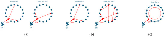
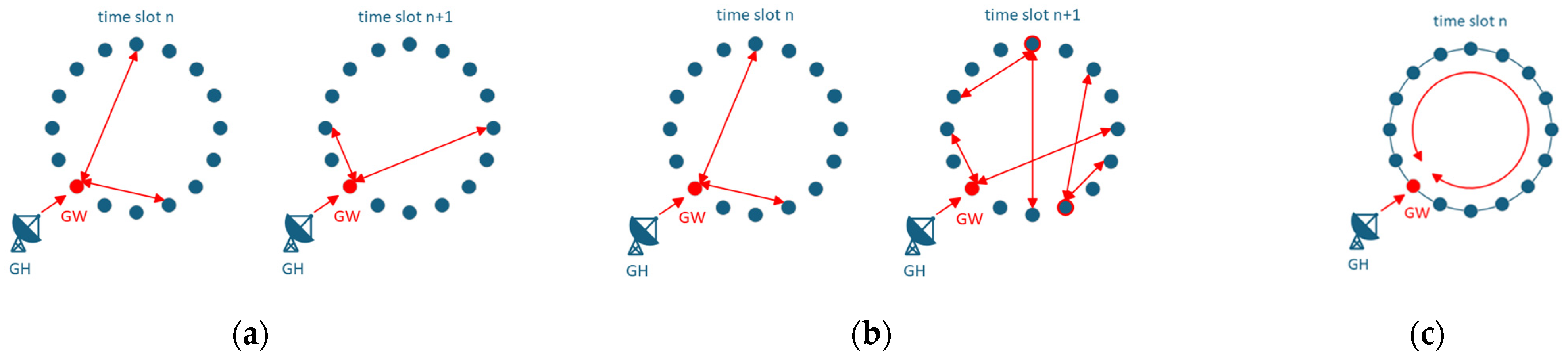
In Multiple Hop (MH) schemes, data sent from the GH to the GW is further broadcast through several satellites until the data reaches the intended target or its defined expiration. In a MH flooding scheme, the satellite will store and (re-)forward data to all satellites at each timeslot, as long as the data is valid. In contrast, in a Real-Time Ring (RTR) scheme, the data is passed through several satellites within the same timeslot (see Figure 1).
Figure 1.
(a) SH network configuration; (b) MH network configuration; (c) RTR network configuration. Each arrow represents a node-to-node connection.
For the RTR to work, during each timeslot the set of all established satellite-to-satellite connections must form closed network rings. These rings that form the network will change at every timeslot (Section 3.4).
2.3. Failure Conditions
As with every satellite payload, ISL payloads can be subject to failures resulting from either nonspecific (with respect to the ISL payload) or specific causes, including:
- Failed acquisition or loss of lock during communication with another satellite;
- Mechanical breakdown of the antennae due to wearing of the moving parts;
- Radiation damage due to prolonged exposure to space (total radiation dose) or Single-Event Upsets (SEUs);
- Physical damage incurred during launch or by in-orbit collisions with debris [7];
- Software anomalies in data management or control algorithms [8].
These failures can either be permanent, if no recovery action can be successfully carried out, or temporary, if nominal operations can still be established. For the purpose of the present paper, all failures are considered non-recoverable within the timeframe of the simulations, i.e., they are treated as permanent.
3. System Design and Network Simulator
3.1. Objective of the Study: RTR Robustness
As pointed out in Section 1 and Section 2, ISL is capable of monitoring and controlling a constellation by making it a network with predictable behaviour through a set of rules. ISL technology is nonetheless complex and subject to failures, as identified in Section 2.3.
It is therefore paramount to assess the robustness of the selected network rules in advance of the operational procedures and to identify possible recovery action when the network deviates from the nominal benchmark behaviour. The purpose of this study is to characterize the Real-Time Ring performance in terms of Time To Disseminate (Section 3.6) in nominal conditions and when multiple failures occur on GW and NG satellites.
The final aim is to demonstrate the robustness of this routing logic and the possibility of its sustaining failures with limited performance degradation even without any intervention from the Ground Segment. Failure isolation and mitigation actions are also characterized.
In this regard, the next sub-chapters present the network simulator set-up, the communication schemes, the contact plans selected and the failure scenarios analysed. The results are reported within the next chapter.
3.2. Software Implementation
An ad hoc simulator developed in C++ emulates ISL network behaviour, focusing on data dissemination from ground stations to satellites. The simulator architecture comprises:
- a Ground Emulator module: simulates ground stations, generates data traffic, and handles transmissions via TT&C link to GW satellites; it also receives telemetry and acknowledgments;
- 36 Satellite Node modules: emulate satellites with two ISL interfaces for inter-satellite connections and one TT&C interface for ground communication (active only for GW satellites);
- a Master Module: manages simulation coordination, satellite-ground station interactions and monitors progress.
Simulation inputs include constellation configuration, link states and data volumes, operating in discrete timeslots. GWs manage TT&C links for uplink and downlink data, while ISL modules operate in half-duplex mode. The simulator dynamically updates ISL configurations including GW satellite roles as per connection matrices. It simulates network scenarios, considering transmission capacity and latency influenced by link availability and failures. Outputs include Time-To-Disseminate (TTD) (see Section 3.6) statistics for analysing network efficiency and optimizing future system developments.
3.3. Connection Matrices Design
The satellites in the network will establish connections that will change over time. This evolution can be described through one or multiple connection matrices [9].
An example of such a matrix for a constellation of four satellites with two ISL payloads each is provided in Table 1, where each row corresponds to a timeslot as described in Section 3.4, during which the indicated satellites will connect. The satellites appearing first in the pairs are the ones transmitting first in the timeslot.
Table 1.
Connection Matrix.
Every network of N nodes can be described by a N × N/2 matrix for every ISL payload.
The design of these matrices is essentially a system trade-off. Maximization of geometrical diversity in the connections over time is a driver for ODTS needs while the reduction of GW–NG revisit times is necessary to minimize M&C data dissemination latencies.
For the purpose of this work, matrices are designed in such a way that maximum geometrical diversity is obtained through a round robin scheme and by exploiting the capability of each satellite to establish two ISL connections at a time.
Essentially, if each satellite has M ISL payloads, the number of timeslots required to contact all the others once is N/M (e.g., for a constellation of 30 Satellites with two payloads each, every 15 timeslots all the possible connections will take place).
Additional flexibility can be introduced by separating the concepts of Nodes and Spacecrafts, i.e., by defining a matrix containing the association between the two with respect to time [10]. This allows the communication scheme to remain synchronized across the constellation while simplifying updates to specific parameters, such as changing satellite roles without altering the number of satellites. Less data to be distributed and updated translate into less complex synchronization to the changes.
3.4. Communication Scheme
The communication between satellite nodes follows a coordinate-timeslot approach where data is transmitted and received according to a time-division duplexing scheme. For every satellite pair defined in a connection matrix (Section 3.3) the transmission and reception of data is performed sequentially.
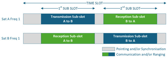
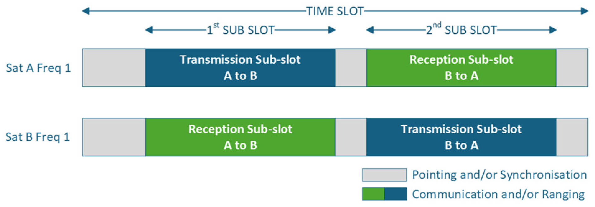
Figure 2 depicts a simplified version of the communication between two satellites at one frequency, e.g., not including a dedicated sub-slot to exchange acknowledgement. Only the time coordinated communication sub-slots are of relevance for this study.
Figure 2.
Timeslot structure.
Each of the two satellite ISL links operates at different frequencies, to reduce mutual interference. For any given satellite, one link is transmitting while the other link is receiving. In a synchronous connectivity scheme, it is mandatory that all satellite nodes of the ISL network be configured with identical slot settings. For this study a slot duration of 40 s and an according sub-slot duration of 15 s for communication have been analysed.
As outlined in Section 2.2, in the RTR dissemination scheme with both links operational, data is forwarded as soon as it arrives within the current timeslot, meaning data received at the interface in reception is sent immediately through the transmitting interface to pass the data through the ring.
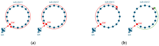
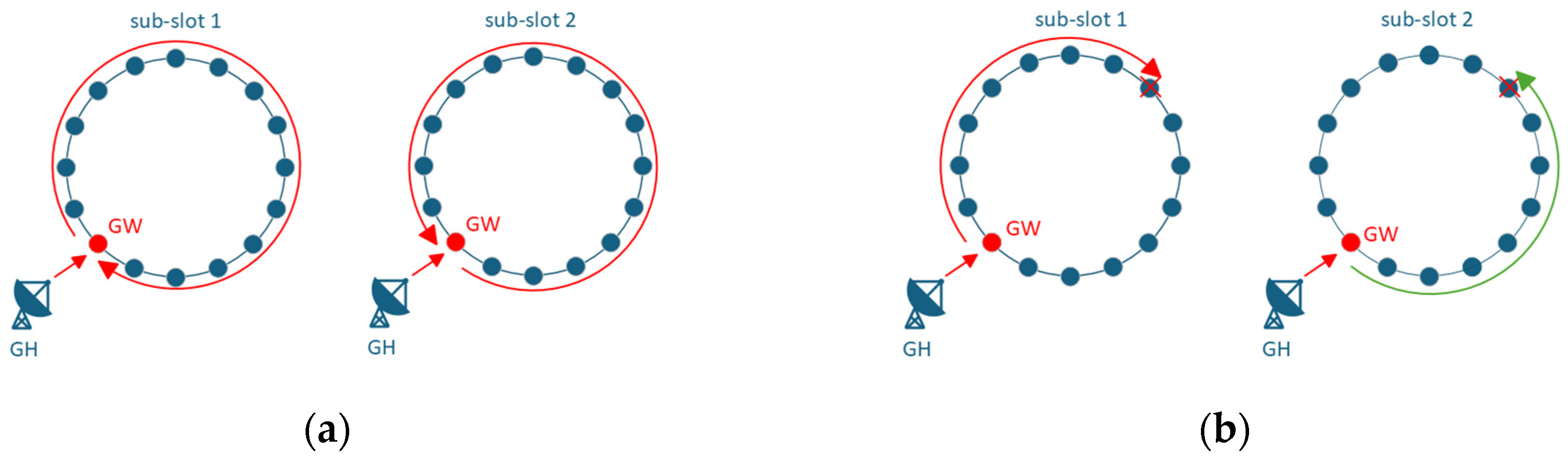
Figure 3a illustrates the data flow in a closed RTR, in the first sub-slot the data passes through the ring in one direction and at the second sub-slot in the opposite direction. Data which cannot be transmitted within the sub-slot, will be transmitted at the next sub-slot either within the same slot or the next slot, as long as the data is valid.
Figure 3.
(a) Data flow in nominal RTR; (b) Data flow in RTR under failure. The arrows represent the direction of the flow of data in the different sub-slots.
The time-division of the information exchange already guarantees some degree of robustness in case one link is not available. In case of a link failure (Section 2.3), one or more satellites, sequentially connected as part of a logical ring, may not be available at a certain time. The data transfer in the ring would be interrupted and need a different path to reach its destination. Once the link unavailability is detected by ground and reflected within the connection matrices, inverting the data flow direction allows, within the same timeslot, the flow of data, i.e., counter clockwise within the first sub-slot (left picture in Figure 3b), through an alternative path during the second sub-slot to the target satellite (right picture in Figure 3b).
3.5. Identification of Scenarios
The RTR dissemination simulations consider nominal (fault-free) and failure scenarios for a constellation of 36 MEO satellites, with four satellites acting as GWs changed every hour. The following assumptions are applicable to all the scenarios:
- Failures last from the start of the simulation (T0) to its end (Tfinal);
- Up to four satellites at a time can be in failure, among which at most two can be GWs;
- Each satellite can fail at most on one of the two payloads;
- Even in presence of failures and with contact replanning, the node roles (GWs, NGs) do not change faster than once per hour;
- The RTR dissemination simulations consider nominal (fault-free) and failure scenarios for a constellation of 36 MEO satellites, with four satellites acting as GWs changed every hour;
- Upon the occurrence of a failure, three different reactions from the ground segment are considered and analysed:
- No intervention (no re-planning) from Ground: the failed SCs can still be selected as GWs for the rest of the simulation, i.e., the Ground Segment does not change the contact plan based on the failed links;
- Re-planning: the failed SC are not selected as GWs for the rest of the simulation, i.e., the Ground Segment only updates the satellites’ roles but not the connectivity scheme;
- Isolated Single-Hop Subnetwork: the failed SCs are not selected as GWs for the rest of the simulation, and they are isolated in a Single-Hop sub-network, eventually with a non-failed SC to reach an even number of satellites.
Given these constraints, the summary of the identified scenarios is hereafter presented in Table 2.
Table 2.
Simulated Scenarios.
Every failure scenario has been simulated with the aforementioned network reaction strategies.
3.6. Key Performance Index
Several KPIs can be used to characterize the behaviour of a network depending on the outcomes of interest. For the purpose of this work, since the identified scenarios consist in failures preventing the correct dissemination of data, the Time to Disseminate (TTD) is considered as pivotal KPI for the comparison and final assessment.
The TTD is defined as the time between the generation of a Telecommand and its complete reception onboard the destination satellite.
The main contributions to TTD are:
- Uplink scheduling: time between the Telecommand generation and the next scheduled GW–NG contact (eventually via other NGs);
- Communication scheme: transmission from GW to final NG (≤timeslot duration);
- On board data handling: processing latency from reception to availability on-board.
All the simulation results are expressed in terms of this parameter and its percentiles. For instance, TTD = 2 min at 99.9% indicates that, throughout the whole simulation, 99.9% of the time any generated telecommand was disseminated in less than two minutes. The average TTD (TTD Avg) is calculated as the 50th percentile.
4. Simulation Results
4.1. Simulations Common Assumptions
All the scenarios were analysed over a 10-day period by using the simulator described in Section 3.2, with the connection matrices designed as described in Section 3.3 and the communication scheme from Section 3.4. It is further assumed that the size of each exchanged frame is 1 kB and ISL payloads exchange data at around 100 kbit/s. Also, every telecommand is considered to be transmitted within one frame.
4.2. Case 1: Fault-Free Benchmark
The results presented in Table 2 represent the baseline performance of the fault-free scenario (i.e., Scenario 1). The TTD 99.9% is always less than two minutes, while the TTD Avg is only 10 s. These metrics represent the performance benchmark of the system when operating in nominal conditions, i.e., in the absence of failure. The results in Section 4.3, Section 4.4 and Section 4.5, representing the failure scenarios mentioned in Table 3, are compared to this benchmark to assess how the network reacts under different stress conditions.
Table 3.
Fault-free benchmark, i.e., Scenario 1.
4.3. Case 2: Failure with No Ground Intervention
Table 4 reports the result from the three failures scenarios, when the ground segment does not intervene on the contact plan as described in Section 3.5.
Table 4.
No-replanning scenario results.
Details of the network behaviour in this case are reported in Table 5, where the performance of both a faulty SC (SC ID 23) and a healthy SC (SC ID 20) are depicted.
Table 5.
Fault-free (H) and faulty (F) SC details for no-replanning scenarios.
4.4. Case 3: Ground Intervention with GWs Replacement
Table 4 reports the results from the three failure scenarios, when the ground segment does not intervene on the contact plan as described in Section 3.5. Table 6 reports the result from the three failures scenarios, when the ground segment implements a simple contact re-planning to avoid failed SCs being used as GWs, as described in Section 3.5.
Table 6.
Re-planning scenario results.
As for the previous case, a useful insight in the results is obtained by observing separately the behaviour of a faulty (SC ID 23) and a healthy SC (SC ID 20), as reported in Table 7.
Table 7.
Fault-free (H) and faulty (F) SC details for re-planning scenarios.
4.5. Case 4: Isolated Single-Hop Sub-Network Strategy
Table 8 reports the results from the three failure scenarios, when the ground segment implements a contact re-planning by isolating the failed SCs into a SH sub-network operating independently from the rest of the constellation, as described in Section 3.5.
Table 8.
Isolated Single-hop subnetwork scenario results.
An insight into the results is provided for this case as well in Table 9, observing the behaviour of a faulty (SC ID 23) and a healthy SC (SC ID 20).
Table 9.
Fault-free (H) and faulty (F) SC detail for Isolated SH sub-network scenarios.
4.6. Results Summary and Discussion
The comparison between a “fault-free” scenario, in Table 3, with the ones for the “no re-planning” failure scenario, in Table 4, shows performance deterioration by nearly two minutes for TTD 99.9% and 10 s for the TTD Avg. Such limited deterioration in performance indicates that RTR is a rather robust routing strategy even in presence of disruptions, ensuring operations within acceptable tolerance even when facing adverse conditions and without ground intervention.
From the comparison between fault-free and faulty SCs in Table 5, it can be seen that:
- Faulty SCs perform worse than the healthy ones in terms of TTD;
- Healthy SCs’ performance also decrease as a consequence of interrupted links. Indeed, results for these SCs deteriorate by approximately one minute for the TTD 99.9% and 10 s for TTD Avg from the fault-free overall ones in Table 3.
The comparison between the “fault-free” benchmark scenario with the “re-planning” case in Table 6 shows performance deterioration aligned with the ones showed by the “no re-planning” scenario in Table 4.
From the comparison between the average performance of the “re-planning” scenarios, in Table 7, with the “no re-planning” ones in Table 4, it can be observed that scenarios “3” and “4” have very similar results, while scenario “2” shows better performance by almost 15 s in terms of TTD 99.9%.
When considering the detailed results per satellite, scenarios “3” and “4” still have very similar results, while scenario “2” shows interesting behaviour: TTD 99.9% of fault-free satellites improves by nearly one minute, while the faulty ones experience an additional one-minute degradation: this indicates that the “re-planning” technique further benefits the healthy nodes and penalizes those already impacted by failures.
The results in Table 4 show that in spite of scenarios 2, 3 and 4 being different in the assumptions (e.g., roles of failed satellites), these differences are not enough to create a consistent variance of the results: when a GW is under failure it still connects to different satellites at every timeslot (Section 2.2), therefore the failure effect (only half bandwidth available for data transmission) is evenly spread among all the nodes that belongs to the same ring as the failed GW. The same applies when a NG satellite is failed and it interrupts the flow of data within the ring. Note also that GW and NG roles change every hour. This is applicable also to results in Table 6.
The comparison between “no re-planning”, in Table 4, and “re-planning”, in Table 6, shows almost no difference: the network ring composition (i.e., the satellites belonging to a certain ring and therefore the GW providing data to that ring) change every timeslot (Section 2.2), therefore the nodes that were affected by a failure at a certain timeslot will be very likely put in a healthy ring (no failures) in the next timeslot. On the other hand, if the GW is in failure, its bandwidth capacity is halved, causing a performance drop.
Finally, since rings change every timeslot, this logic is not applicable to the “SH sub-network” failure cases, because the failed satellites form a dedicated SH network. Considering this mitigation strategy, the overall performance shown in Table 8 is aligned with the previous failure scenarios.
The detailed analysis on the fault-free and faulty SCs performance in Table 9 shows that this scenario yields the best performance for fault-free nodes compared to all previous cases, while performance of faulty satellites remains consistent with the degradation observed in the previous cases. Essentially, in this scenario the failed spacecrafts are isolated from the rest of the constellation and their performance becomes independent.
Indeed, in this scenario, the healthy SCs average and maximum TTD are aligned to the constellation-wise ones of the fault-free scenario in Table 3, indicating this strategy as the best one to tackle ISL network single payload failure. This clearly comes at the cost of a higher workload in the ground segment operations, that need to be justified considering the other cases show rather robust behaviour and limited degradation in performance.
5. Conclusions
A comprehensive analysis of the performance of an ISL network composed of 36 MEO satellites has been carried out in a fault-free scenario and under different failure conditions. Three different reactions to failures were implemented and compared to assess the robustness of the network and the best reaction to unexpected failures.
In spite of the necessity of having two active ISL links for the Real-Time Ring to work, this routing logic has shown to be robust to permanent failures even in the case of limited actions from the Ground Segment to mitigate the network outage.
From a system point of view, although the half-duplex links cannot rely on real-time transmission feedback to identify a failure, the Ground Segment will notice the failures either through the lack of reception acknowledgements or through dedicated telemetries received from the failed satellites reporting the status of the ISL payloads.
The performance comparison among the three mitigation strategies highlights that the “Isolated Single-Hop Subnetwork” is the most effective since it delivers the best performance for fault-free SC, ensuring latencies (TTD) aligned with the baseline fault-free scenario. The re-planning actions needed to inform the satellites of the new configuration—including the dissemination of a new connection matrix—can be executed fast enough to limit disruptions, bounding the time window when the worst performance is experienced. The benefits offered by RTR in terms of low latencies and the half-duplex scheme reverting the data transmission direction after half a timeslot in case of a broken node in the rings still ensures TTD good enough to outmatch the drawbacks caused by the interruption of the rings and possible loss of data in the first moments following the failures.
This demonstrates the Real-Time Ring logic ability to maintain network efficiency and reliability, making it the preferred choice for ensuring robust performance in fault-tolerant environments.
The follow-up of this work will explore the behaviour of an ISL network for a multi-orbit constellation (LEO, MEO, GEO) and the possibility of exploiting full-duplex Optical links (OISL) and evaluating the potential improvement in performance when traded-off with the increase in system complexity.
Author Contributions
Conceptualization, E.E.Z., C.W. and P.C.N.; methodology, C.W., and E.E.Z.; software, A.M.; validation, C.W.; formal analysis, E.E.Z. and P.C.N.; investigation, P.C.N. and A.M.; resources, C.W.; data curation, C.W. and E.E.Z.; writing—original draft preparation, E.E.Z., C.W. and P.C.N.; writing—review and editing, C.W., E.E.Z., and P.C.N.; visualization, E.E.Z.; supervision, C.W.; project administration, C.W. All authors have read and agreed to the published version of the manuscript.
Funding
This research received no external funding.
Institutional Review Board Statement
Not applicable.
Informed Consent Statement
Not applicable.
Data Availability Statement
Data are available in this manuscript.
Conflicts of Interest
A contract for the execution of a project exists between the European Space Agency, from which author an is employed and Thales Alenia Space Italia, from which author Enrico Edoardo Zini is employed. Telespazio Belgium, from which author Pasquale Christian Neto is employed and Wiser Srl, from which author Andrea Morelli is employed, are both sub-contractor of Thales Alenia Space Italia within the framework of the mentioned project. The authors declare that the research was conducted in the absence of any commercial or financial relationships that could be construed as a potential conflict of interest.
References
- InsideGNSS. BeiDou Completes Inter-Satellite Link Testing; Only GNSS with This Accuracy-Improving Feature. Available online: https://insidegnss.com/beidou-completes-inter-satellite-link-testing-only-gnss-with-this-accuracy-improving-feature/ (accessed on 22 October 2024).
- Rajan, J.A.; Orr, M.; Wang, P. On-Orbit Validation of GPS IIR Autonomous Navigation. In Proceedings of the 59th Annual Meeting of The Institute of Navigation and CIGTF 22nd Guidance Test Symposium (2003), Albuquerque, NM, USA, 23–25 June 2003. [Google Scholar]
- ESA. Galileo Second Generation Satellites Take Shape. 5 December 2023. Available online: https://www.esa.int/Applications/Satellite_navigation/Galileo/Galileo_Second_Generation_satellites_take_shape (accessed on 21 September 2024).
- About GLONASS. Available online: https://glonass-iac.ru/en/about_glonass/ (accessed on 22 October 2024).
- Motzigemba, M.; Zech, H.; Biller, P. Optical Inter Satellite Links for Broadband Networks. In Proceedings of the 2019 9th International Conference on Recent Advances in Space Technologies (RAST), Istanbul, Turkey, 11–14 June 2019. [Google Scholar]
- Vergoossen, T.; Loarte, S.; Bedington, R.; Kuiper, H.; Ling, A. Modelling of satellite constellations for trusted node QKD networks. Acta Astronaut. 2020, 173, 164–171. [Google Scholar] [CrossRef] [Scilit]
- Pechkis, D.L.; Pacheco, N.S.; Botting, T.W. Statistical approach to the operational testing of space fence. IEEE Aerosp. Electron. Syst. Mag. 2016, 31, 30–39. [Google Scholar] [CrossRef] [Scilit]
- Hastings, D.E.; Garrett, H.B. Spacecraft-Environment Interactions; Cambridge University Press: Cambridge, UK, 2004. [Google Scholar]
- Zini, E.; Rana, N.; Mortellaro, A. Use of MEO-LEO Inter-Satellite Link Measurements for on-Board Autonomous ODTS of GNSS Satellites. In Proceedings of the 75th International Astronautical Congress (IAC), Milan, Italy, 14–18 October 2024. [Google Scholar]
- Li, Y.; Wu, J.; Kang, G.; Chen, L.; Qiu, Y.; Zhou, W. A Flexible Topology Control Strategy for Mega-Constellations via Inter-Satellite Links Based on Dynamic Link Optimization. Aerospace 2024, 11, 510. [Google Scholar] [CrossRef] [Scilit]

Disclaimer/Publisher’s Note: The statements, opinions and data contained in all publications are solely those of the individual author(s) and contributor(s) and not of MDPI and/or the editor(s). MDPI and/or the editor(s) disclaim responsibility for any injury to people or property resulting from any ideas, methods, instructions or products referred to in the content. |
© 2026 by the authors. Licensee MDPI, Basel, Switzerland. This article is an open access article distributed under the terms and conditions of the Creative Commons Attribution (CC BY) license.