


Abstract
Seismic performance evaluation of existing buildings is essential for defining effective mitigation strategies in earthquake-prone regions. This study investigates the seismic performance of low-rise unreinforced masonry (URM) residential buildings located in several cities in the Albanian territory. Material properties were obtained from experimental tests conducted on representative samples and subsequently adopted in the development of analytical models. Three-dimensional finite element models were generated based on the collected geometric data and experimentally determined material characteristics. Nonlinear static (pushover) analyses were carried out to assess the seismic capacity and identify the potential failure mechanisms of the buildings. The numerical results showed significant variation in performance depending on the building typology, with some cases reaching the near-collapse limit state under design-level earthquakes. The capacity curves and performance points obtained from the models demonstrate the pronounced influence of construction techniques, boundary conditions, and material properties on the seismic response. The results indicated that URM residential buildings exhibit distinctive seismic performance characteristics influenced by their construction techniques and material properties. Based on the findings, recommendations for retrofit strategies are proposed to enhance the seismic resilience of such structures.
1. Introduction
1.1. Albania Building Stock After November 2019 Earthquake
The devastating effects of recent earthquakes worldwide, such as the 2023 Türkiye–Syria, the 2016 Central Italy, and the 2015 Nepal events, have demonstrated the catastrophic impact of seismic activity on vulnerable building stock. These disasters caused widespread collapses and loss of life, particularly among older unreinforced masonry buildings, highlighting the urgent need for preventive measures such as structural assessment and retrofitting.
On 26 November 2019, a magnitude Mw 6.4 earthquake struck central-western Albania, causing severe damage in Durrës, Tirana, and nearby settlements. Albania’s building stock mainly consists of structures with massive load-bearing walls, reinforced-concrete frames, or non-load-bearing infill walls made of bricks or concrete blocks, while mixed systems are also common.
Most buildings in Albania were designed according to the national seismic codes (KTP-63, KTP-78, KTP-89) [1], which offered limited consideration of earthquake loads. As a result, many existing structures exhibit inadequate seismic safety, similar to conditions observed in other European countries with aging building stocks.
1.2. Literature Review
The Eurocodes forming the basis of this study include EN 1990 Basis of Structural Design [2], EN 1991 Actions on Structures [3], EN 1992 Design of Concrete Structures [4], EN 1993 Design of Steel Structures [5], EN 1996 Design of Masonry Structures [6], and EN 1998 Design of Structures for Earthquake Resistance [7].
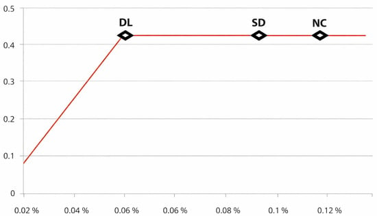
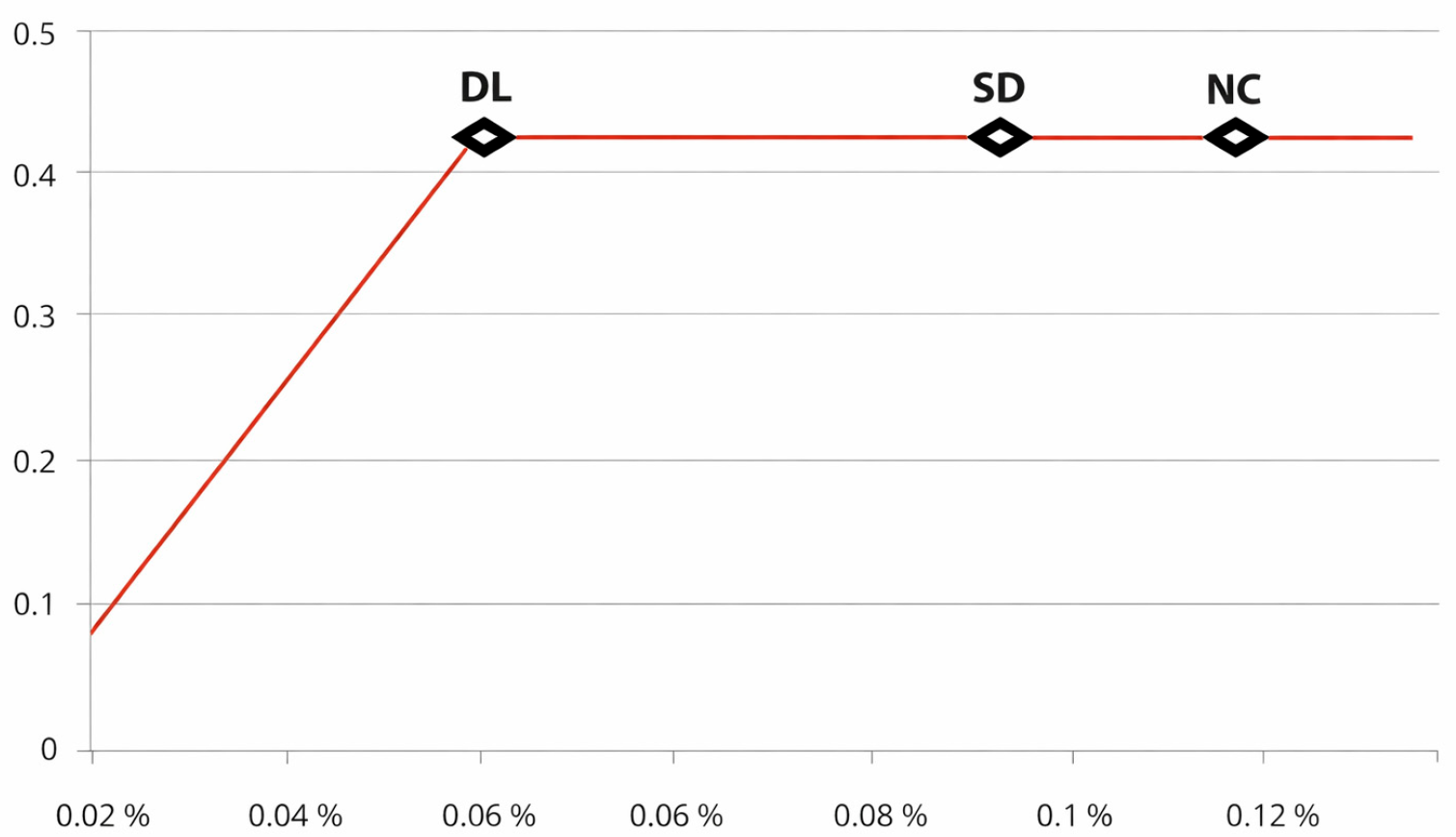
Eurocode 8 defines the fundamental principles of seismic design, relating seismic force to the maximum ground acceleration and soil characteristics, which together determine the elastic spectrum used for design. The structural capacity—defined as the maximum horizontal force sustained without collapse—is evaluated through nonlinear pushover analysis, represented by a force–displacement curve at the control node. For simplicity, this capacity curve is typically idealized as bilinear, distinguishing the elastic and plastic response phases, shown below in Figure 1.
Figure 1.
Capacity curve of the object [7].
Eurocode 8 (EC-8) categorizes the performance level of a structure based on the anticipated degree of damage following a specific earthquake. These classifications are as follows:
- DL—Damage Limitation: At this level, the structure sustains no structural damage, though non-structural elements may be affected.
- SD—Significant Damage: This phase entails structural damage to the building, which is reparable and does not jeopardize the safety of occupants.
- NC—Near Collapse: At this critical level, the structure incurs severe structural damage, potentially endangering the lives of occupants.
In addition to empirical and macro-modeling approaches, recent studies have also employed advanced finite element methods to capture the complex behavior of masonry structures under seismic loading. These works provide valuable insight into cracking patterns, energy dissipation, and collapse mechanisms, serving as a reference for analytical validation [8]. The integration of experimental material testing, detailed geometric surveys, and nonlinear spectrum-based assessment provides a comprehensive evaluation of their seismic capacity. The approach not only identifies failure mechanisms but also proposes retrofit strategies, thereby offering practical recommendations for enhancing the seismic resilience of the Albanian masonry building stock.
2. Study Case, Investigation and Laboratory Testing
2.1. Building Description and Damage Investigation
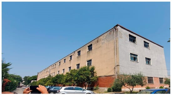
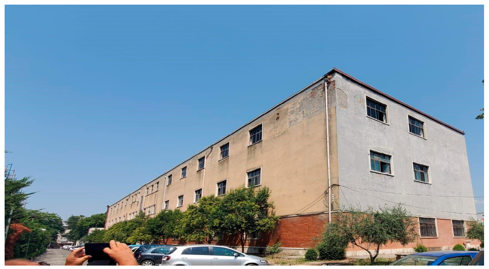
Constructed around the 1940s, the studied building features a load-bearing solid wall structure composed of concrete blocks without seismic reinforcements. The building, situated on Dibra Street in Tirana, possesses a regular geometric plan and dimensions, with a total area of 5062.8 m2. Originally conceived as a load-bearing solid wall structure with concrete blocks—a hallmark of Italian architecture prevalent during its era of construction—the building underwent modifications in the early 1990s. During this period, a third floor was added, constructed as a load-bearing solid wall structure using clay bricks. These bricks, however, exhibit relatively lower resistance compared to concrete blocks. Consequently, the third floor features a lower floor height and incorporates different materials in its construction, diverging from the original design. The condition of the building was assessed based on a thorough on-site inspection, taking into consideration modern seismic construction codes such as EC-6 and EC-8. Below in Figure 2 is shown the view of the building.
Figure 2.
The inspected building in the field.
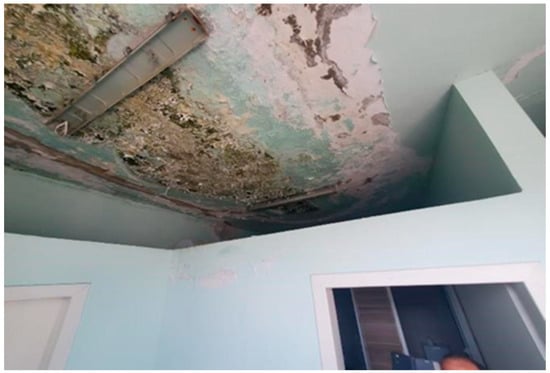
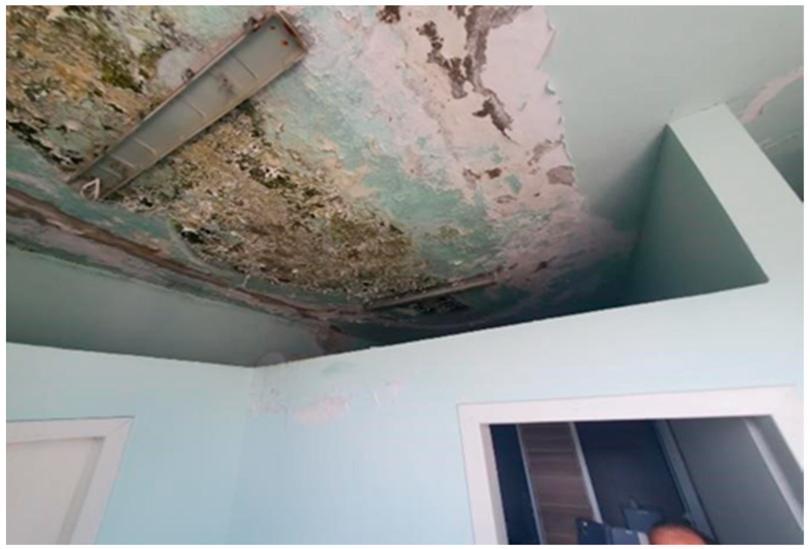
The building includes a 5 m high ground floor, a 5 m high first floor, and a 3 m high second floor, each covering about 1897.6 m2. Load-bearing walls—0.38 m thick at the ground floor and 0.25 m on the upper levels—run in both longitudinal and transverse directions, ensuring good continuity between stories. The third floor that was added later retains the same plan but differs in height and material, using weaker clay brick masonry that reduces overall stiffness and strength. The slabs are generally undamaged, except for minor moisture-related deterioration observed in the second-floor ceiling slab, as shown in Figure 3.
Figure 3.
Damage to floor slabs and perimeter walls on the top floor.
Various areas of damage are evident throughout the building, predominantly in the form of cracks and small-to-medium-sized openings. This damage is primarily concentrated in corners, particularly at the connections between walls and between the slab and wall interfaces. Due to its longitudinal dimension being larger than its transverse dimension (105.54 m compared to 17.96 m), the building exhibits torsional behavior during seismic movements. This collision has resulted in significant damage, particularly evident on the second floor in this section of the building. Building plan is shown in Figure 4.
Figure 4.
The floor plan of the building.
2.2. Laboratory Tests and Material Properties
Material properties were obtained from on-site laboratory tests conducted by Altea & GeoStudio2000 and used directly in this assessment. In the absence of original project data, the mechanical characteristics adopted in the analytical models are derived from these results. Compression tests on the floor slabs were performed in accordance with EN 1204-1 [9]. Cores were extracted with height-to-diameter ratios of 1:1 (cubic) and 2:1 (cylindrical), leveled by grinding, and tested under compression. The slabs consist of C30/37 concrete with a thickness of 15 cm, which provides sufficient strength and durability. Tests on the masonry components indicated that the first two floors are built with C12/15 concrete blocks (≈12 MPa), while the third floor uses solid clay bricks with a compressive strength of fb = 7.5 MPa—both acceptable for load-bearing masonry per KTP-89 and EC-8. The mortar in all levels exhibits fm = 2.5 MPa, below the EC-8 minimum (5 MPa), indicating a weak bond and reduced tensile capacity. The average parameters derived from the tests, are given in Table 1 below and were used in the numerical model, with masonry properties correlated from brick and mortar strength in accordance with Eurocode provisions.
Table 1.
Mechanical properties of masonry.
3. Analytical Modeling and Seismic Analysis
3.1. Analytical Modelling and Pushover Analysis
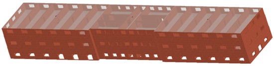
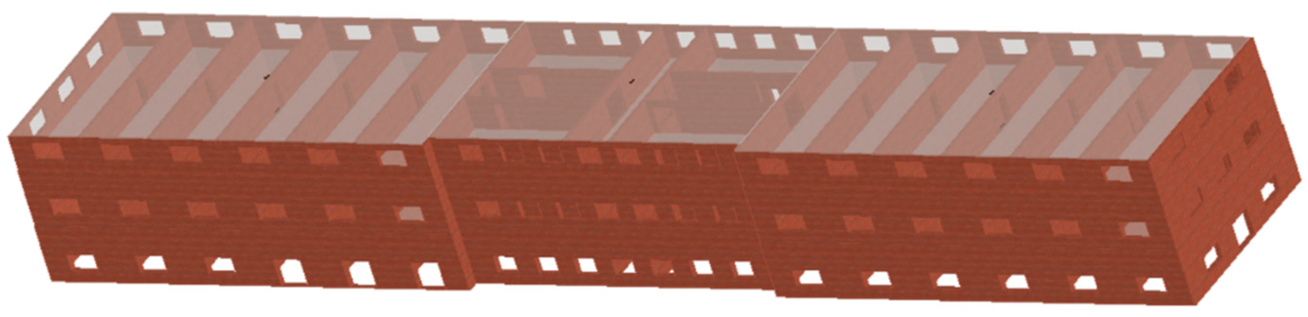
The assessment of the TREMURI structure involves two main stages: automated generation of the equivalent frame model and subsequent nonlinear static (pushover) analysis to define the capacity curve representing the force–displacement relationship at the control node [10]. The three-dimensional model incorporates the main load-bearing walls, diaphragms, and openings, based on in situ geometric data and experimental material properties. The equivalent frame approach accurately captures both global and local mechanisms while remaining computationally efficient. The generated model is visually represented through its structural components—piers, lintels, beams, tie rods, and columns—which can be manually adjusted for specific conditions. Model is shown in Figure 5 below.
Figure 5.
Three-dimensional mathematical model of the structure.
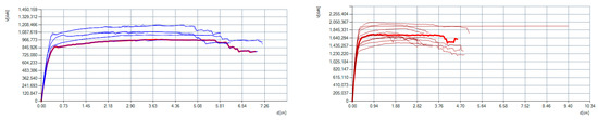
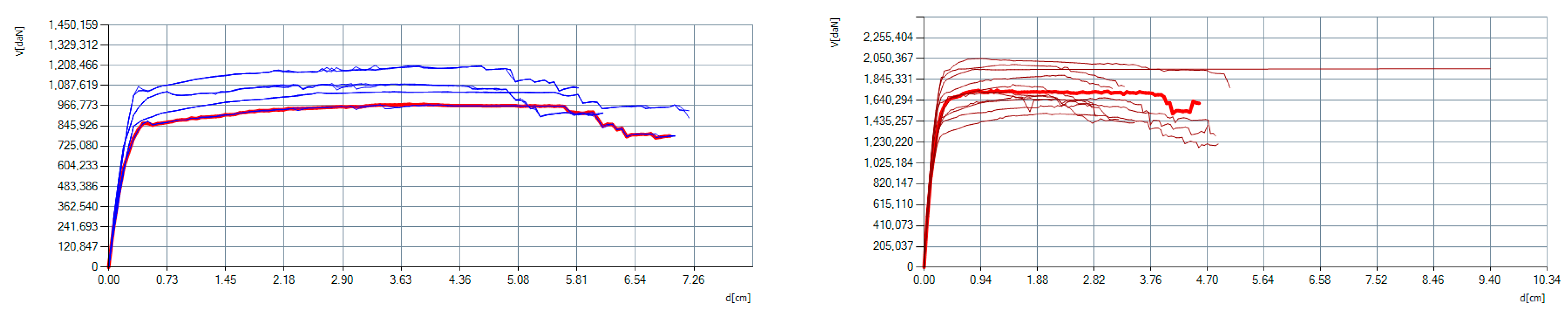
In nonlinear analyses, loads are incrementally increased to produce the horizontal displacement of the structure [11]. The analysis continues until a predefined displacement—automatically calculated—indicates structural collapse, generating the capacity curve that describes the building’s behavior under increasing lateral loads. In total, 24 analyses were performed, accounting for different load scenarios, directions, and eccentricities, shown in Figure 6 below.
Figure 6.
Pushover analysis 12 cases in x-direction (left) and 12 cases in y-direction (right).
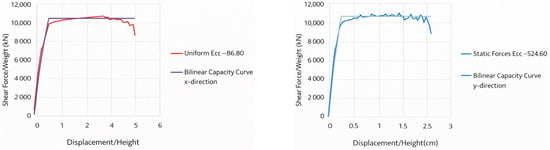
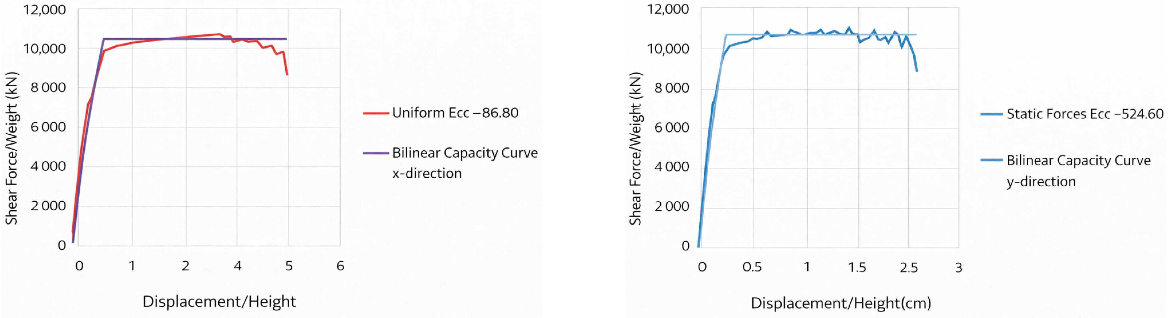
For each of the 12 curves, the worst-case scenario—or the situation with the least amount of energy dissipation—is selected as the representative capacity curve in each direction (x and y), shown in Figure 7 below. The building was assumed to be founded on stiff soil (EC8 soil class B), with fixed support conditions at the foundation level. A damping ratio of 5% was adopted in the analyses, consistent with common practice for masonry buildings.
Figure 7.
Capacity curve in x-direction (left) and y-direction (right).
The capacity curve is then bilinearized using the N2 method, which combines nonlinear static and dynamic analyses in three steps. First, stiffness, strength, and ductility are obtained from the pushover analysis of the multi-degree-of-freedom (MDOF) system. Second, an equivalent single-degree-of-freedom (SDOF) system is defined, assuming a constant deflected shape during seismic loading, with its nonlinear properties derived from the base shear–top displacement curve. Finally, the maximum displacement of the equivalent SDOF system is determined through nonlinear dynamic analysis.
3.2. Spectrum-Based Assessment
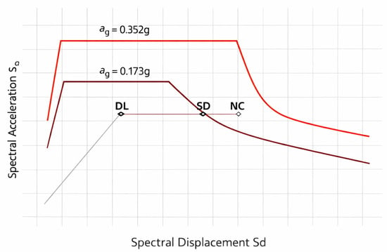
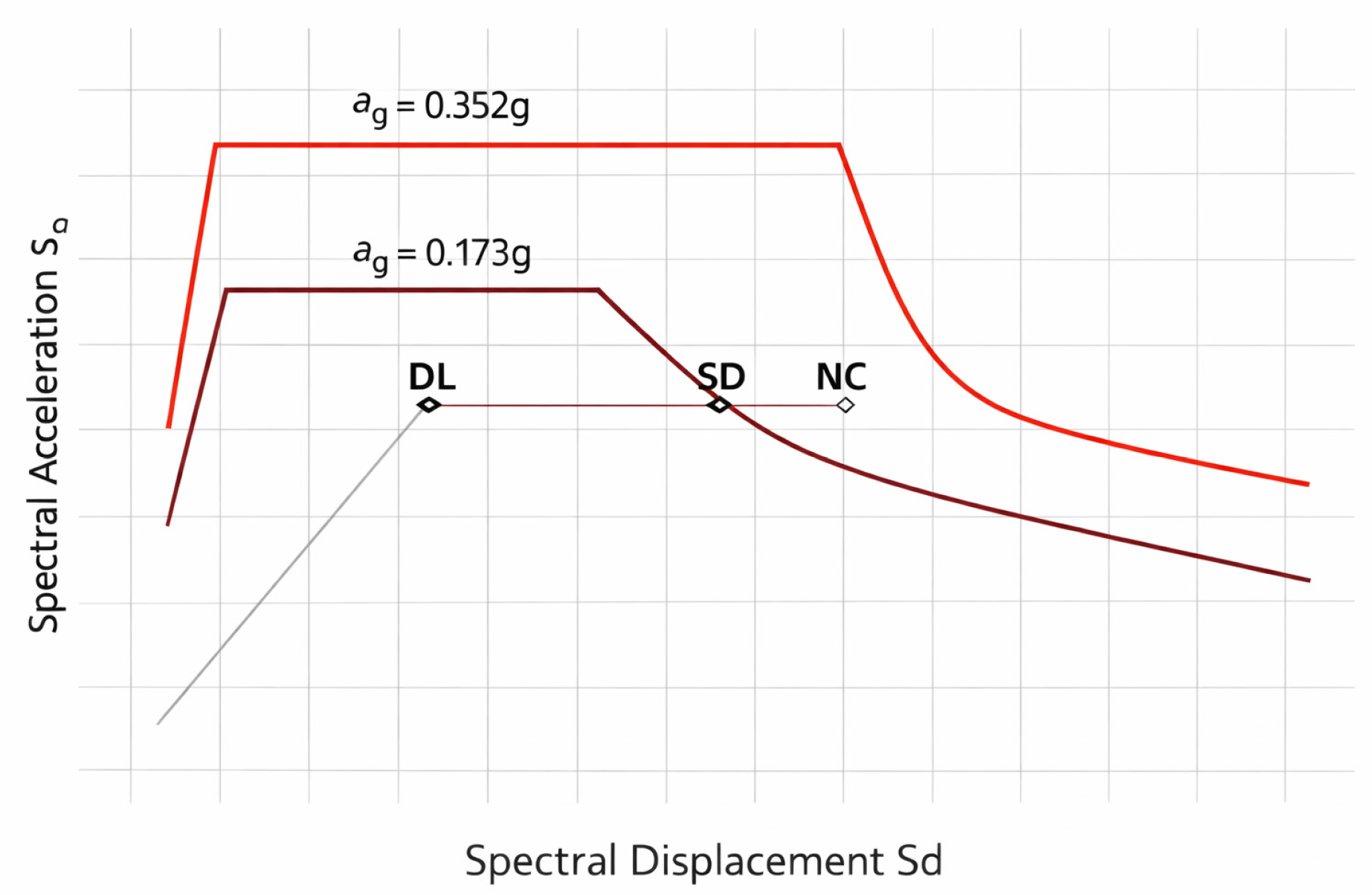
Peak Ground Acceleration (PGA) was calculated considering Type B soil (Vs = 450.9 m/s) for two return periods in accordance with Eurocode 8: 95 years (10% in 10 years) and 475 years (10% in 50 years). For the 475-year event (non-collapse condition), the PGA at the foundation level is 0.352 g; with soil factor S = 1.20, the design acceleration is derived. For the 95-year event (Damage Limitation condition), PGA = 0.173 g, adjusted by the same soil factor [12]. The structural capacity is then compared with the design spectrum (Sa–Sd format), verifying performance at the DL level for 0.173 g and SD level for 0.352 g, with analysis focused on the weaker y-direction, as shown in Figure 8 below.
Figure 8.
Capacity vs demand of the studied building model.
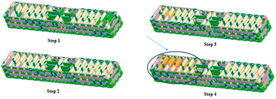
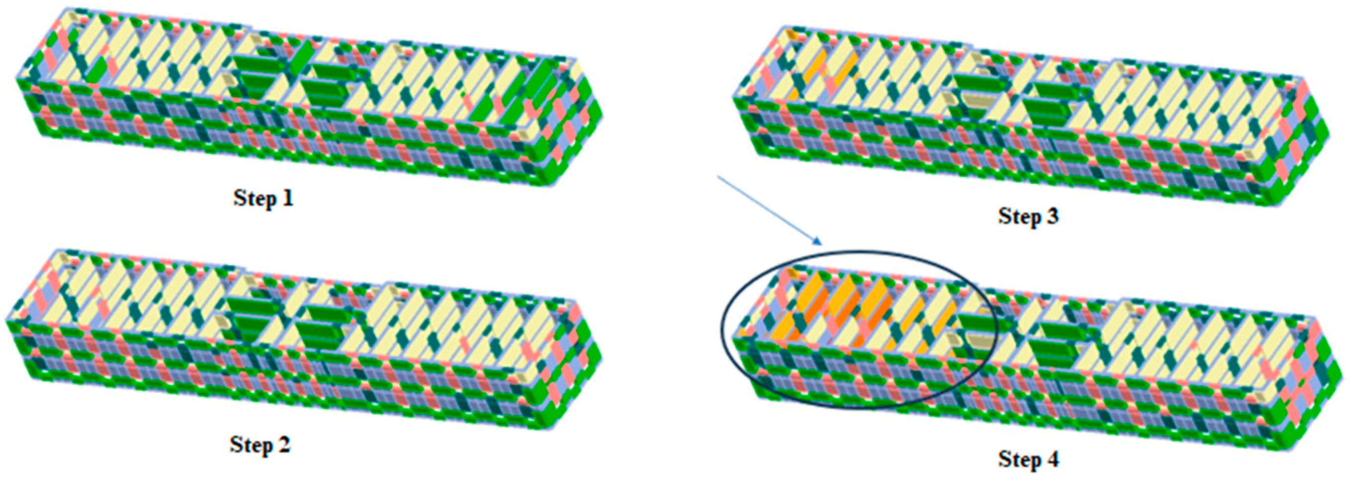
The comparison shown in the figure indicates that for the 95-year return period (ag = 0.173 g), the structure exceeds the Damage Limitation (DL) level and enters the Significant Damage (SD) phase, meaning it does not satisfy EC-8 requirements [13]. For the 475-year earthquake (ag = 0.352 g), the response surpasses the Near-Collapse (NC) threshold, showing that even the non-collapse condition is not met and the building would be at serious risk during strong shaking. In Figure 9 are shown step by step damage patterns and failure mechanism of the building model.
Figure 9.
Step-by-step damage patterns of the building.
4. Conclusions
The analyses show that the structure fails to meet the Damage Limitation and Non-Collapse performance levels defined by Eurocode 8, confirming the need for strengthening to achieve adequate energy dissipation and deformation capacity.
Based on these results, the expert group recommends the following retrofit measures, designed in accordance with Albanian and Eurocode provisions:
- -
- Reinforced Concrete Columns: Add new RC columns from foundation to roof, fully connected to existing beams and walls.
- -
- Floor Slabs and Beams: Strengthen with Carbon Fiber-Reinforced Polymer (CFRP) to increase stiffness and load-bearing capacity.
- -
- Load-Bearing Walls: Apply concrete or steel jacketing to improve strength and ductility in damaged walls.
- -
- Foundations: Reconstruct and extend foundations to accommodate new vertical and lateral loads.
The proposed retrofitting strategy can also serve as a reference for similar low-rise masonry buildings across the Balkan region, where comparable construction typologies and deficiencies are observed.
Author Contributions
Conceptualization, M.H. and H.B.; methodology, M.H.; software, M.H.; validation, M.H., H.B. and A.B.; formal analysis, M.H.; investigation, A.B.; resources, A.B.; data curation, M.H.; writing—original draft preparation, M.H.; writing—review and editing, M.H.; visualization, M.H.; supervision, H.B. All authors have read and agreed to the published version of the manuscript.
Funding
This research received no external funding.
Institutional Review Board Statement
Not applicable.
Informed Consent Statement
Not applicable.
Data Availability Statement
The data presented in this study are available upon request from the corresponding author.
Conflicts of Interest
The authors declare no conflict of interest.
References
- KTP-N.2-89; Technical Conditions for the Design of Anti-Seismic Constructions. Academy of Sciences: Tirana, Albania, 1989.
- EN 1990:2002/A1:2005; Eurocode 0: Basis of Structural Design. European Union: Brussels, Belgium, 2005.
- EN 1991-1-1:2002; Eurocode 1: Actions on Structures. European Union: Brussels, Belgium, 2002.
- EN 1992-1-1:2004; Eurocode 2: Design of Concrete Structures—Part 1-1: General Rules and Rules for Buildings. European Union: Brussels, Belgium, 2004.
- EN 1993-1-1-2005; Eurocode 3: Design of Steel Structures—Part 1-1: General Rules and Rules for Buildings. European Union: Brussels, Belgium, 2005.
- EN 1996-1; Eurocode 6: European Masonry Design Code. “Design of Masonry Structures. Part 1: General Rules for Reinforced and Unreinforced Masonry Structures”. European Union: Brussels, Belgium, 2005.
- EN 1998-1; Eurocode 8 European Seismic Design Code. “Design of Structures for Earthquake Resistance. Part 1: General Rules, Seismic Actions and Rules for Buildings”. European Union: Brussels, Belgium, 2004.
- Lourenço, P.B. Computations on historic masonry structures. Can. J. Civ. Eng. 2007, 34, 1465–1477. [Google Scholar] [CrossRef] [Scilit]
- EN 12004-1; Adhesives for Ceramic Tiles—Part 1: Requirements, Assessment and Verification of Constancy of Performance, Classification and Marking. European Committee for Standardization, CEN: Brussels, Belgium, 2017.
- Lagomarsino, S.; Penna, A.; Galasco, A.; Cattari, S. TREMURI Program: An equivalent frame model for the nonlinear seismic analysis of masonry buildings. Eng. Struct. 2013, 56, 1787–1799. [Google Scholar] [CrossRef] [Scilit]
- Harmonization of Seismic Hazard Maps for the Western Balkan Countries; ORFEUS; NATO SfP Project No. 983054; Institut d’Estudius Catalanas: Barcelona, Spain, 2008.
- IGJEUM. The Earthquake in Durrës on November 26, 2019; IGJEUM: Tirana, Albania, 2020. [Google Scholar]
- INGV. Characteristics of Adriatic Sea Earthquake 26.11.2019; National Intitute of Geo-Physics and Vulcanology: Rome, Italy, 2019. [Google Scholar]



Disclaimer/Publisher’s Note: The statements, opinions and data contained in all publications are solely those of the individual author(s) and contributor(s) and not of MDPI and/or the editor(s). MDPI and/or the editor(s) disclaim responsibility for any injury to people or property resulting from any ideas, methods, instructions or products referred to in the content. |
© 2026 by the authors. Licensee MDPI, Basel, Switzerland. This article is an open access article distributed under the terms and conditions of the Creative Commons Attribution (CC BY) license.