


Abstract
Friction stir spot welding (FSSW) is a novel variant of Friction Stir welding (FSW), developed by Mazda Motors and Kawasaki Heavy Industries to join similar and dissimilar materials in a solid state. It is an economic and environmentally friendly alternative to resistance spot welding (RSW). The FSSW technique, however, includes some structural defects imbedded within the weld joint, such as keyhole formation, hook crack, and bond line oxidation challenging the joint strength. The unique properties of nanomaterials in the reinforcement of metal matrices motivated researchers to enhance the FSSW joints’ strength. Previous studies successfully fabricated nano-reinforced FSSW joints. At different volumetric ratios of nano-reinforcement, nanoparticles may agglomerate due to inefficient stirring of the welding tool pin, forming stress concentration sites and brittle phases, affecting tensile and fatigue strength under static and cyclic loading conditions, respectively. This work investigated how the welding tool pin affects stirring efficiency by controlling the distribution of a nano-reinforcing material within the joint stir zone (SZ), and thus the tensile and fatigue strength of the FSSW joints. Sheets of AA6061-T6 of 1.8 mm thickness were used as a base material. In addition, graphene nanoplatelets (GNPs) with lateral sizes of 1–10 µm and thicknesses of 3–9 nm were used as nano-reinforcements. GNP-reinforced FSSW specimens were prepared and successfully fabricated. Optical microscope (OM) and field emission scanning electron microscope (FE-SEM) methods were employed to visualize the GNPs’ incorporation into the SZs of the FSSW joints. Micrographs of as-welded specimens showed lower formations of scattered, clustered GNPs achieved by the threaded pin tool compared to continuous agglomerations observed when the cylindrical pin tool was used. Tensile test results revealed a significant improvement of about 30% exhibited by the threaded pin tool compared to the cylindrical pin tool, while fatigue test showed an improvement of 46–24% for the low- and high-cycle fatigue, respectively.
Keywords:
FSSW; hook crack; GNP-reinforcement; tool pin; fatigue behavior; stirring effect; lap joint; joint strength 1. Introduction
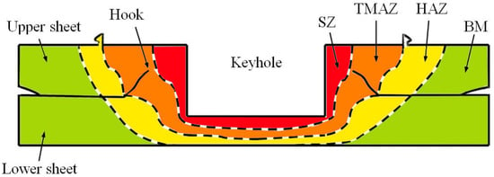
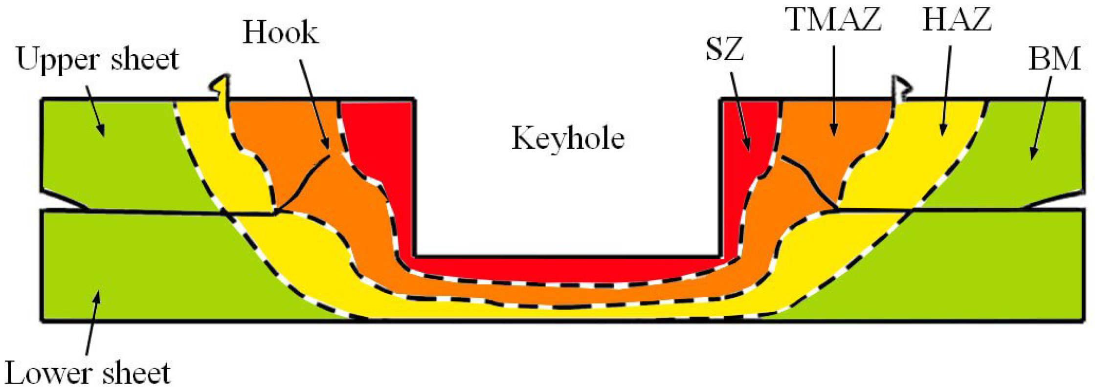
Friction stir spot welding technique (FSSW) is a solid state welding method, developed as a feasible alternative to resistance spot welding, and employed for light-weight materials, such as aluminum, magnesium, titanium, etc. FSSW has many economic, environmental, and operational advantages, as it makes it possible to weld similar and different metals and alloys, including those previously classified as non-weldable [1]. FSSW has become an integral part of various fields of modern industries in automobiles, aircraft, aerospace, shipbuilding, trains, etc. The FSSW joint microstructure is characterized by four distinct neighboring zones around the joint keyhole, namely stir zone (SZ), thermomechanically affected zone (TMAZ), heat-affected zone (HAZ), in addition to the base material (BM), as shown in Schematic Figure 1. Depending on the frictional heat experienced and material flow induced during welding, these zones have different microstructures. In addition, the joint cross-section includes an upwardly curved crack, extending from the joint interface. Welding process parameters, such as tool rotation speed, dwell time, tool plunge rate, and tool plunge depth, mainly govern the FSSW joint strength.
Figure 1.
Schematic illustration of the FSSW joint cross-section showing the joint features.
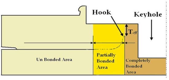
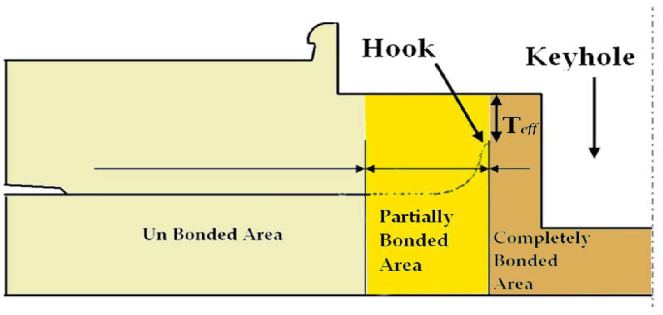
Despite the economic and environmental feasibility achieved, FSSW joints still include challenging structural defects that affect their quality and durability, such as keyhole formation, the characteristic hook defect, and the joint bond line oxidation [2], as illustrated in schematic Figure 2. Researchers and industrialists have introduced many additives to improve the mechanical properties of this technique under different operating and loading conditions. Light materials have also undergone additional techniques to increase the strength-to-weight ratio to reduce the weight of structures and means of transportation, reducing the cost of fuel consumed and the environmental impact of using fossil fuels.
Figure 2.
Schematic illustration of the FSSW joint cross-section showing the joint bond line and the structural defects included.
Many previous studies have diagnosed, analyzed, and characterized some of these defects and investigated the feasibility of employing some techniques to address their implications on the durability of the FSSW welded joints under static and cyclic loading conditions. Alkhafaji et al. [3] significantly improved the mechanical properties by optimizing the most dominant welding process parameters. In another study [4], they investigated the role of the welding tool geometry in determining the joint quality and strength. Zou et al. [5] investigated the effect of refilling the FSSW joints’ keyhole on the mechanical properties and microstructure. They achieved refilled joints with a tensile-shear strength improved by nearly 26% compared to the conventional ones at identical conditions. However, no significant improvement was achieved in the hook crack morphology. In another research endeavor, Suresh et al. [6] compared FSSWed AA5083-H116 joints, reinforced by SiC of micro and nano scales, to investigate the effect of the filler material size on the microstructural and mechanical characterization. The authors concluded that the nano-SiC-reinforced joints exhibited improvement of 29.3%, 23.3%, and 26.3% in tensile strength, hardness, and wear resistance, respectively, compared with joints reinforced by SiC particles of the micro scale. Mohan et al. [7] successfully incorporated graphene nano-platelets (GNPs) into the SZs of FSSW joints of AA7075 aluminum alloy. They reported significant grain refinement in the joint SZ, which was attributed to the GNPs acting as grain growth barriers during welding. Their reinforced FSSW joints exhibited an improvement in tensile strength of 52.6% compared to those without reinforcement.
Meanwhile, Fereiduni et al. [8] fabricated Fe2O3 nanoparticles into a matrix of Al 5083 FSSW joints. They observed three patterns of the nanomaterial distribution within the joints SZs, only one of which is uniform. In a previous study conducted by our research team, Alkhafaji et al. [9], the authors studied the static and fatigue behavior of FSSW joints reinforced by GNPs. The experimental results revealed significant improvement in the static strength of the joint, despite detecting GNP agglomerations within the SZs of the welded joints. This phenomenon is attributed to the lower stirring efficiency in SZ away from the tool pin, and thus the non-uniform distribution of the GNPs within the joint matrix. In all studies [6,7,8,9], the same phenomenon was diagnosed. These agglomerations are considered as regions of stress concentration and brittle phases that are typical sites for cracks to initiate and extend, in addition to converting the joint failure from ductile to brittle behavior, resulting in static and fatigue failure under static and cyclic loads, respectively [9].
This work aims to demonstrate the role of the welding pin geometry on the distribution of the GNPs within the joint matrix and thus prevent the formation of brittle phases resulting from nano-agglomerates that deteriorate the fatigue strength.
2. Materials and Methods
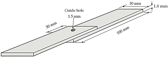
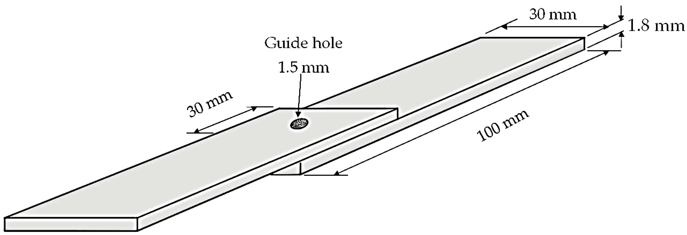
During this work, lap-shear specimens were prepared from AA6061-T6 aluminum of 1.8 mm thick, with dimensions of 100 mm × 30 mm and a lap area of 30 mm × 30 mm, as shown in schematic Figure 3. A guide hole of 1.5 mm in diameter and 2.5 mm in depth was created at the center of the lap area of each specimen. GNPs of 1 to 10 µm lateral sizes and 3 to 9 nm thicknesses, from the Sixth Element (Changzhou) Materials Technology Co., Ltd. (Changzhou, China) were used as nano-reinforcement particles. Considering the guide hole volume of a 4.4 mm3 filled with fully compacted GNPs, added to each lap-shear specimen and the geometry of the SZ obtained from cross-sectional images of performed joints, the volume fraction of the produced composites in the SZ of welds was calculated to be about 18.5%.
Figure 3.
Schematic of the FSSW lap-shear specimen, including the created guide hole that was filled with GNPs.
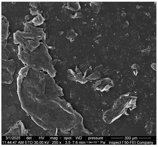
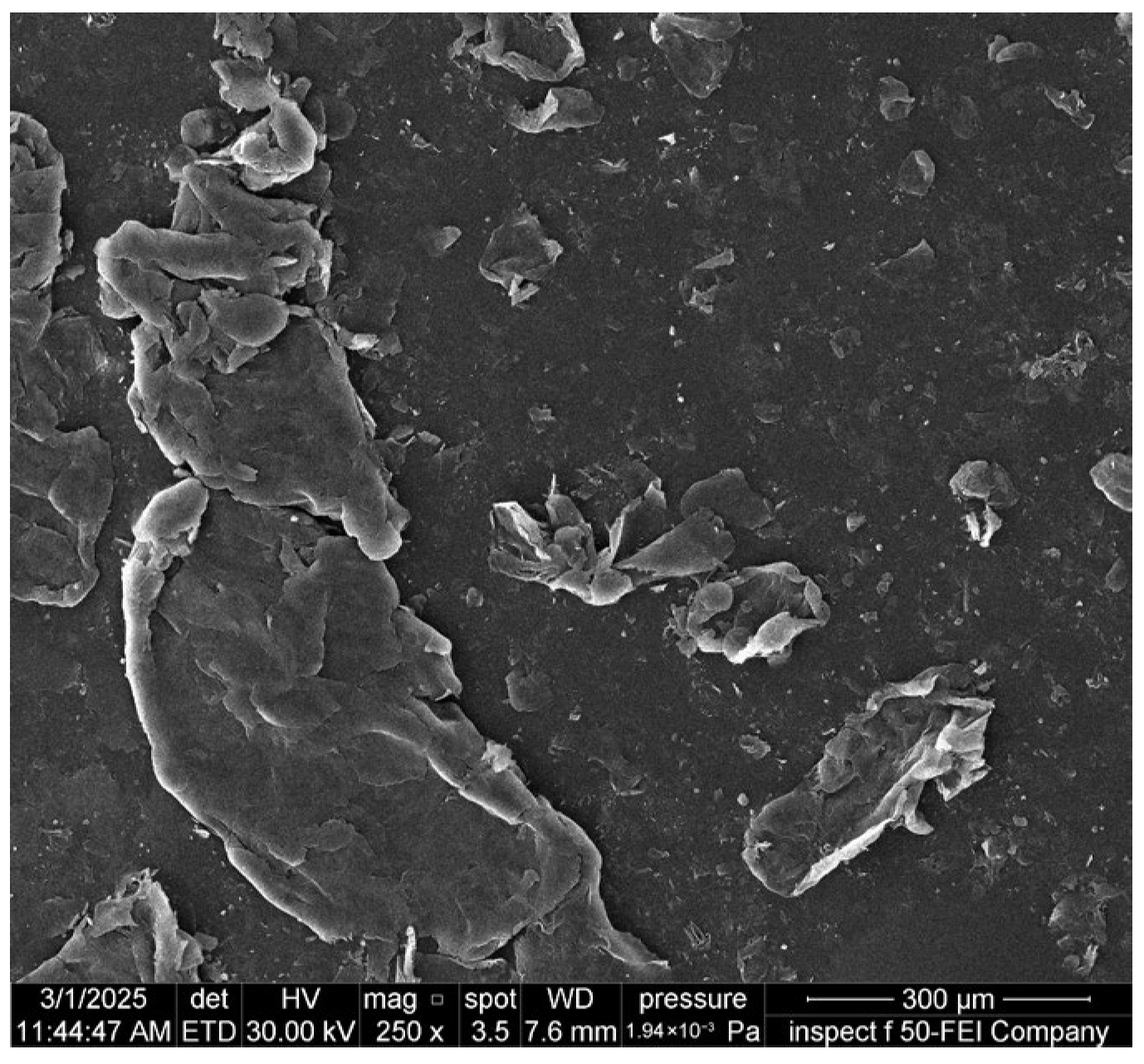
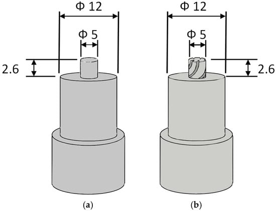
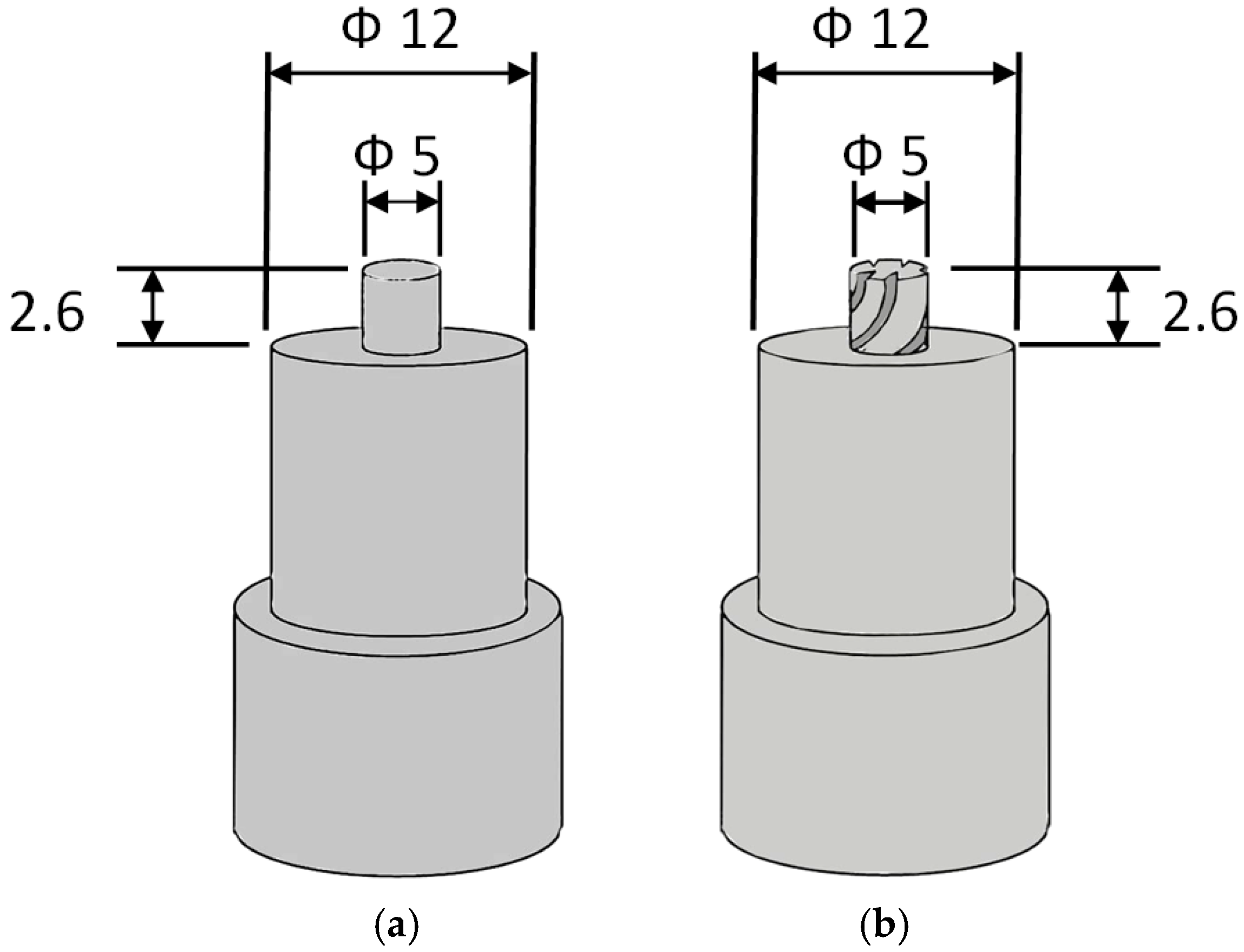
Metallographic observations were conducted using ZEISS Merlin field-emission scanning electron microscope (FE-SEM) from Carl Zeiss Microscopy GmbH, Oberkochen, Germany. Figure 4 shows FE-SEM micrograph of as-received GNPs. Two welding tools made of H13 tool steel were prepared and hardened to 48–50 HRC. The tools were machined to an identical shoulder diameter of 12 mm and different pin profiles, cylindrical and threaded pins, as shown in schematic Figure 5. The MAHO MH 400T, CNC milling machine (Germany, Bavaria) was used to conduct the welding processes. The Taguchi method was employed to determine a set of welding process parameters, which were identical throughout the experiment. The welding tool was rotated at 600 rpm with a dwell time of 16 s, a plunge depth of 0.3 mm, and a tool plunge rate of 10 mm/min. Two sets of lap-shear specimens were performed at the center of the lap area. Tensile test was conducted at room temperature with a 1 mm/min loading rate using a QUASAR 25, Cardano al Campo (VA), Italy, tensile testing device. The average of three tensile-tested joints from each welding condition was used to evaluate the tensile strength (TS). A standard fatigue test was conducted to determine the number of cycles to failure (Nf) of each specimen. A maximum fatigue test load corresponding to 80% of the tensile strength (TS) was applied [1,2,9,10]. Four load levels were applied with a 10% decrement between each level. The test was conducted on an MST 809 Axial/Torsional Test System (Eden Prairie, MN, USA) at a sinusoidal stress ratio of R = 0.1 and a frequency controlled from 10 to 30 Hz, depending on the test load ranges. A fatigue life of 104 is considered as a dividing limit between low- and high-cycle fatigue conditions. This categorization is specific to this study and is intended to facilitate understanding of fatigue behavior at different load levels of the fatigue test. The results of three fatigue-tested specimens were averaged to evaluate the fatigue life at each individual load level.
Figure 4.
FE-SEM of as-received GNPs.
Figure 5.
Schematic illustration of the FSSW tools employed during this study: (a) cylindrical pin tool; (b) threaded pin tool.
3. Results and Discussion
3.1. Micrograph
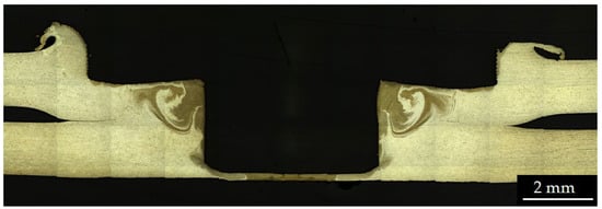
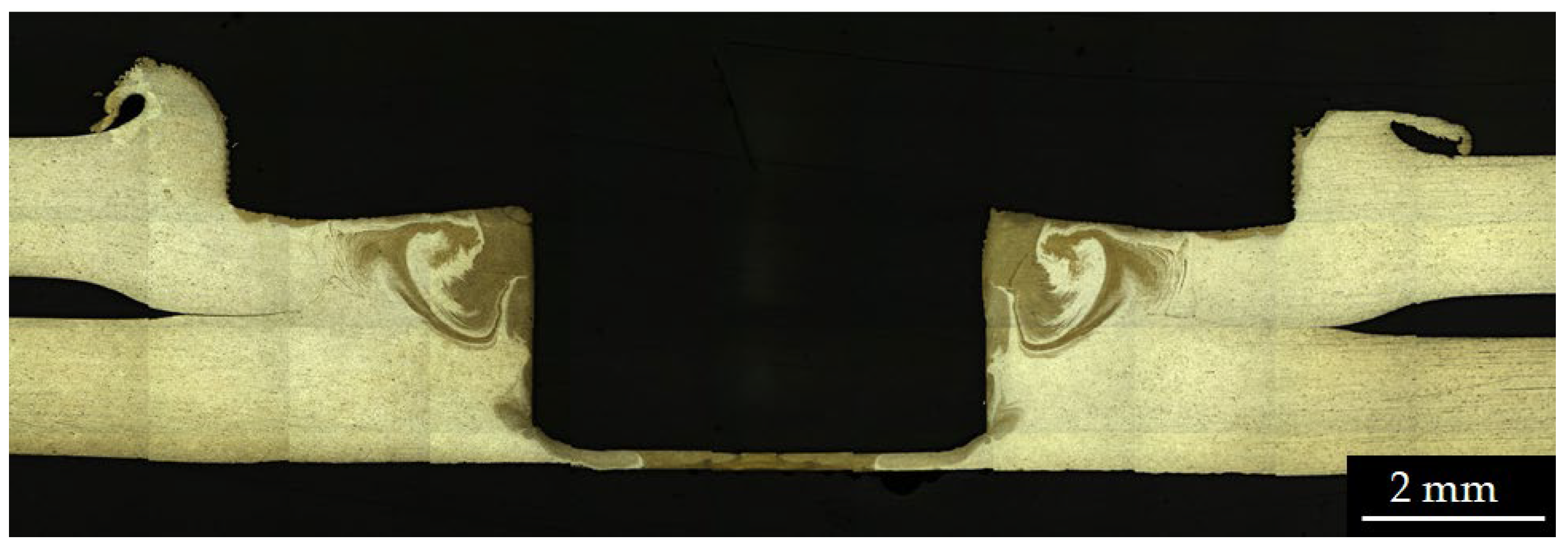
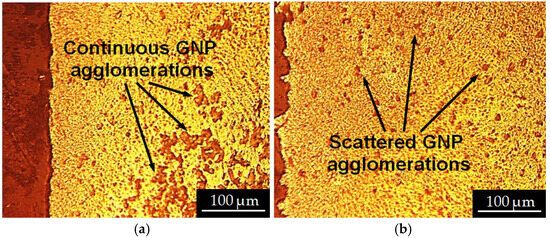
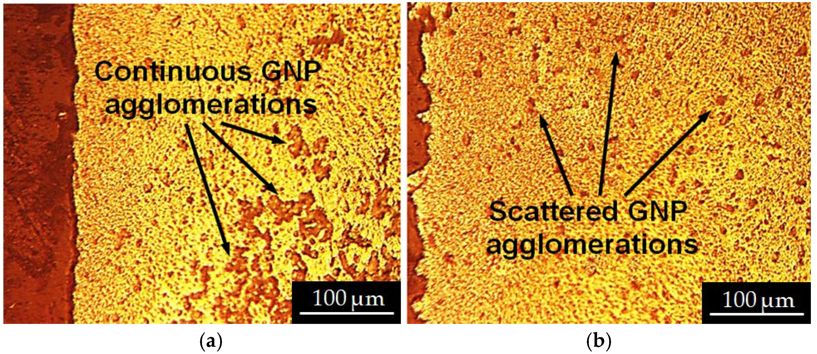
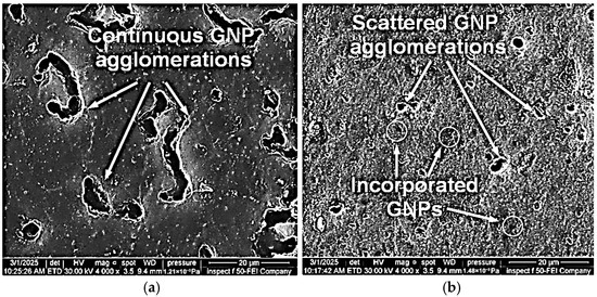
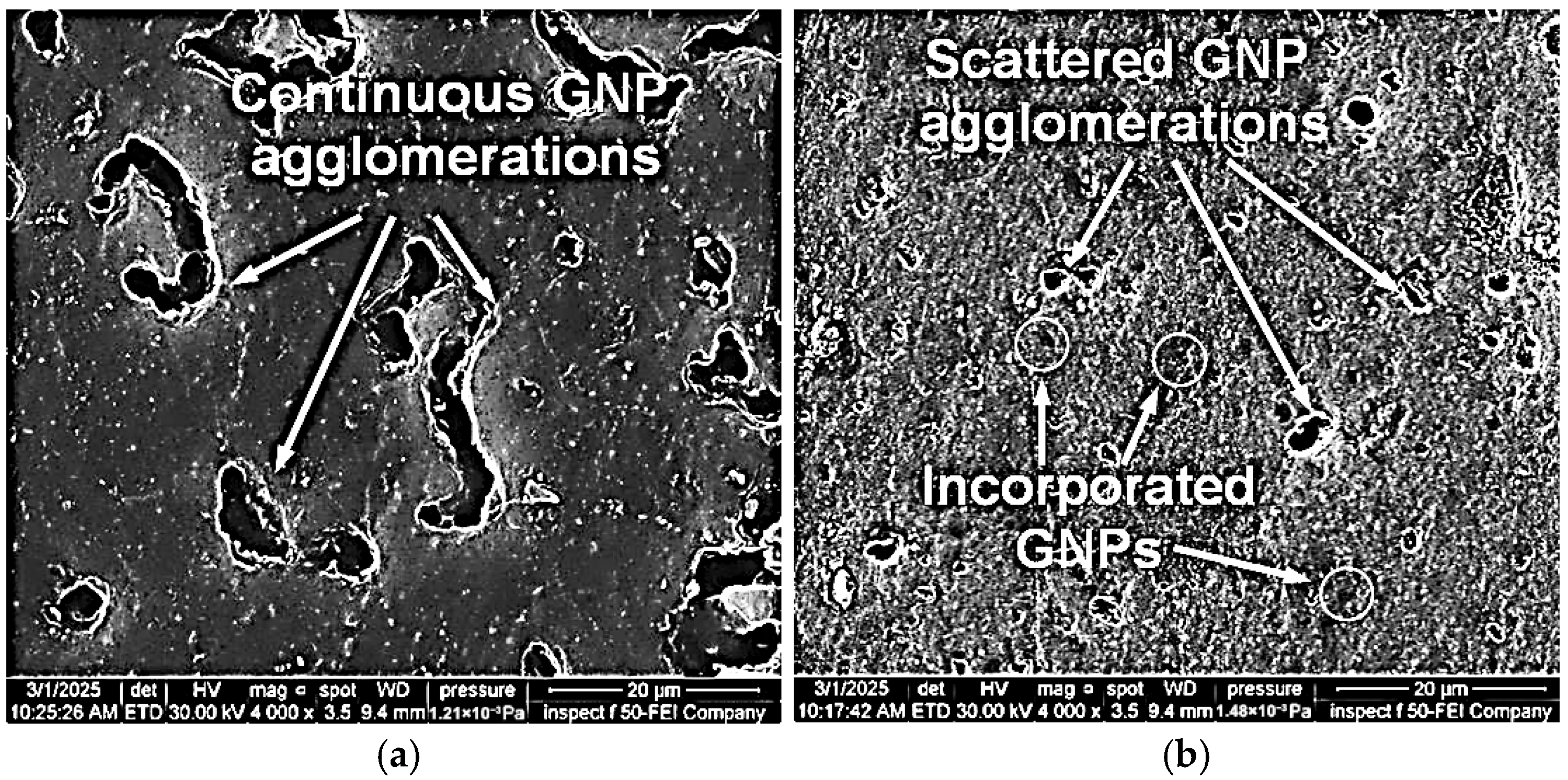
Figure 6 shows a cross-section of a typical GNP-reinforced FSSW lap joint, while Figure 7a,b and Figure 8a,b show OM and FE-SEM micrographs of SZs of FSSW joints performed using cylindrical and threaded pin tools, respectively.
Figure 6.
Typical GNP-reinforced FSSW joint.
Figure 7.
OM micrographs of cross-sectioned FSSW joints illustrating the formation and distribution of GNP agglomerations: (a) performed using cylindrical pin tool; (b) performed using threaded pin tool.
Figure 8.
FE-SEM micrographs of cross-sectioned FSSW joints, illustrating the GNPs distribution and agglomeration within the joints: (a) performed using cylindrical pin tool; (b) performed using threaded pin tool.
Figure 8 shows typical incorporation of GNPs within the joint SZ. However, continuous and scattered GNP agglomerations were observed in the SZs of joints produced by the cylindrical and threaded pin tools, respectively. Figure 7a and Figure 8a illustrate spatial distribution of the GNP agglomerations within the SZs. The figures visualize uniformly dispersed agglomerations almost observed at the core of the SZs, associated with the increased stirring effect and higher material flow closer to the tool pin [7,8,9] compared with relatively large-sized and continuous agglomerations of 20–60 µm clustered at the periphery. On the other hand, micrographs of Figure 7b and Figure 8b show smaller and more uniformly distributed agglomerates, typically below ~5–15 µm in size, reflecting a significantly improved stirring efficiency within the joints’ SZs, achieved by employing the threaded pin tool compared to the cylindrical pin tool. It is worth mentioning that micrographs and their scale bars were used to estimate sizes of the GNP agglomerations by taking multiple locations within the SZ.
3.2. Tensile Strength
An average TS of 6.130 kN was exhibited by the FSSW joints welded by the threaded pin tool compared to 4.650 kN for the cylindrical pin tool. This improvement is attributed to the more uniform distribution of the GNPs, resulting in low-content scattered agglomerations associated with the higher stirring efficiency achieved. Therefore, tensile strength is related to morphological purity in the SZ and lower content of voids, which are typical sites for stress concentration and potential sources for developing and propagating shear cracks [2,9].
3.3. Fatigue Strength and Failure Modes
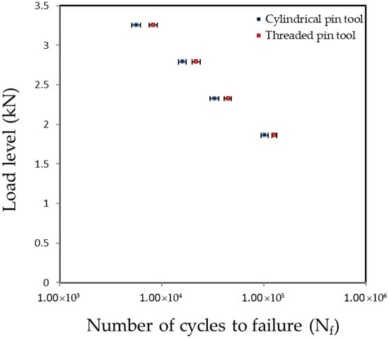
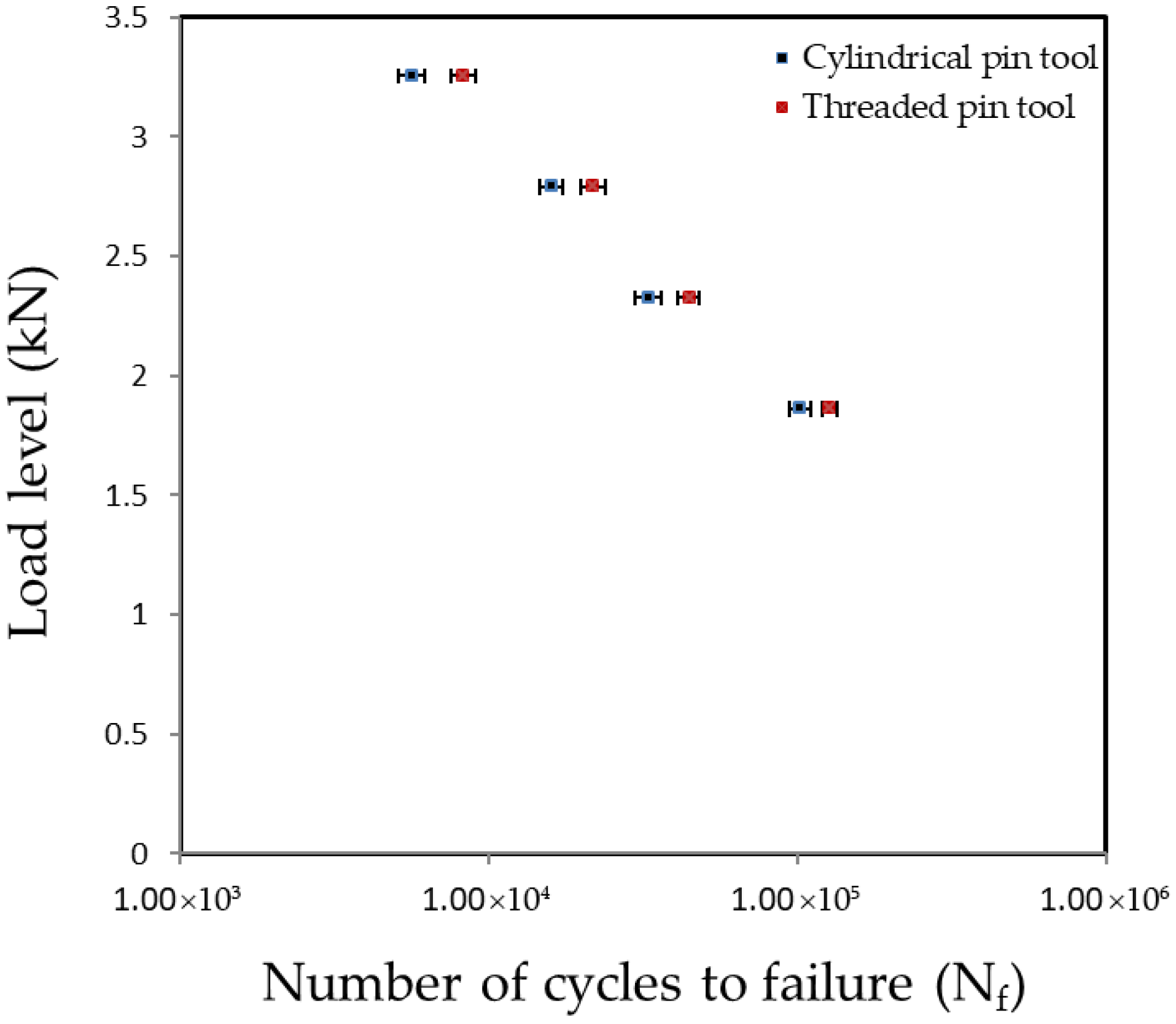
A step-by-step, detailed fatigue failure mechanism has been demonstrated in a previous study, conducted by our research team at Alkhafaji et al. [2]. The fatigue mechanism involved crack initiation and the most probable crack propagation paths under cyclic loading, leading to the complete separation of the joint sheets and the corresponding expected failure mode, in addition to the corresponding expected failure modes. Figure 9 shows fatigue test results of two sets of FSSW joints, performed using cylindrical and threaded pins welding tools. Although the fatigue test was carried out under exactly identical welding conditions, the error bars of standard deviation shown in the figure demonstrate some dispersion in the test results due to slight differences in the distribution of the GNPs within the joint matrix, local voids, and porosity.
Figure 9.
Experimental results of fatigue test in number of cycles to failure (Nf) at four test load levels.
The experimental fatigue test results revealed 8.25 × 10³ cycles and 1.27 × 10⁵ cycles exhibited by the threaded pin tool compared to 5.65 × 10³ and 1.02 × 10⁵ at low- and high-cycle fatigue conditions, respectively. This improvement in fatigue strength is attributed to the lower inclusion of scattered GNPs agglomerations, compared to the high content of continuous agglomerations in the SZ induced by the cylindrical pin tool, as shown in the OM and FE-SEM micrographs of Figure 8. The improved fatigue strength is associated with the structural integrity achieved by morphology improvement in the SZ in the form of lower inclusions of micro-voids and brittle phases, which are typical origins of fatigue cracks [9].
Various modes of failure were observed at different load levels. Shear fracture mode is observed in both welding conditions at low-cycle fatigue conditions. However, the nugget pull-out mode is observed at the end of the fatigue test for joints performed by the threaded pin tool, whereas at high-cycle fatigue conditions, specimens from both welding conditions exhibited a circumferential failure mode, and a lower sheet transverse fracture was observed while testing joints welded by the threaded pin tool. Table 1 summarizes different failure modes observed during this study, corresponding to their welding conditions and fracture surfaces. It is worth noting that shear fracture mode is associated with lower strength joints, while joints of higher strength usually exhibit circumferential failure mode and lower sheet transverse fracture. A similar trend of failure modes is commonly observed in previous studies [1,2,9,10].
Table 1.
Summary of failure modes observed during the fatigue test corresponding to the welding condition.
4. Conclusions
This work investigated the effect of stirring efficiency on fatigue durability of GNP-reinforced AA6061-T6 FSSW joints by utilizing cylindrical and threaded pin tools. The study was conducted based on experimental methods and visual observations, and the following conclusions and findings were made:
- (1)
- GNPs are successfully incorporated within the SZ of the FSSW welded joints by utilizing both cylindrical and threaded pin tools.
- (2)
- Experimental results revealed significant improvement in both tensile and fatigue strength achieved using the threaded pin tool. This improvement is attributed to the lower inclusion of scattered GNPs agglomerations, compared to the high content of continuous agglomerations in the SZ induced by the cylindrical pin tool, and thus lower brittle phases and stress concentration sites included within the joints SZs.
- (3)
- The FSSW joints performed by the threaded pin tool exhibited tensile strength of 32% compared with the cylindrical pin tool.
- (4)
- On the other hand, an improvement varying between 46 and 24% was achieved in fatigue strength by using the threaded pin tool at low- and high-cycle conditions over that of the joints performed by the cylindrical pin tool.
Author Contributions
Conceptualization, A.A. and D.C.; methodology, A.A. and D.C.; data curation, A.A.; investigation, A.A. and D.C.; writing—original draft preparation, A.A.; writing—review and editing, A.A. and D.C.; visualization, A.A.; supervision, D.C.; project administration, A.A. All authors have read and agreed to the published version of the manuscript.
Funding
This research received no external funding.
Data Availability Statement
Data are available upon request from the corresponding author.
Conflicts of Interest
The authors declared no conflict of interest.
References
- Shahani, A.R.; Farrahi, A. Effect of Sheet Thickness on Fatigue Behavior of Friction Stir Spot Weld of Al 6061-T6 Lap-Shear Configuration. J. Stress Anal. 2018, 3, 61–68. [Google Scholar]
- Alkhafaji, A.; Camas, D.; Al-Asadi, H. Effect of Inert Gas Cover on the Static and Fatigue Behavior of AA6061-T6 Aluminum Alloy Friction Stir Spot Lap-Shear Welds. Materials 2025, 18, 256. [Google Scholar] [CrossRef] [Scilit] [PubMed]
- Alkhafaji, A.; Camas, D. Effect of Tool Rotational Speed and Dwell Time on the Joint Strength of Friction Stir Spot Welded AA6061-T6 Sheets. Eng. Proc. 2023, 56, 215. [Google Scholar]
- Alkhafaji, A.; Camas, D.; Lopez-Crespo, P.; Al-Asadi, H. The influence of tool geometry on the mechanical properties and the microstructure of AA6061-T6 aluminum alloy friction stir spot welding. Materials 2023, 16, 4135. [Google Scholar] [CrossRef] [Scilit] [PubMed]
- Zou, Y.; Li, W.; Yang, X.; Su, Y.; Chu, Q.; Shen, Z. Microstructure and mechanical properties of refill friction stir spot welded joints: Effects of tool size and welding parameters. J. Mater. Res. Technol. 2022, 21, 5066–5080. [Google Scholar] [CrossRef] [Scilit]
- Suresh, S.; Natarajan, E.; Franz, G.; Rajesh, S. Differentiation in the SiC filler size effect in the mechanical and tribological properties of friction-spot-welded AA5083-H116 alloy. Fibers 2022, 10, 109. [Google Scholar] [CrossRef] [Scilit]
- Mohan, A.E.; Sajuri, Z.; Baghdadi, A.H.; Jamadon, N.H.; Abbasi, M. Influences of graphene nano-platelet addition and pin lengths on the microstructure and mechanical properties of 7075 aluminum alloy under friction stir spot welding. J. Mater. Res. Technol. 2024, 31, 3436–3452. [Google Scholar] [CrossRef] [Scilit]
- Fereiduni, E.; Movahedi, M.; Baghdadchi, A. Ultrahigh-strength friction stir spot welds of aluminum alloy obtained by Fe3O4 nanoparticles. Sci. Technol. Weld. Join. 2018, 23, 63–70. [Google Scholar] [CrossRef] [Scilit]
- Alkhafaji, A.; Camas, D.; Al-Asadi, H. Static and Fatigue Strength of Graphene Nanoplatelet-Reinforced AA6061-T6 Friction Stir Spot-Welded Lap Joints. J. Manuf. Mater. Process. 2025, 9, 98. [Google Scholar] [CrossRef] [Scilit]
- Shahani, A.R.; Farrahi, A. Experimental investigation and numerical modeling of the fatigue crack growth in friction stir spot welding of lap-shear specimen. Int. J. Fatigue 2019, 125, 520–529. [Google Scholar] [CrossRef] [Scilit]



Disclaimer/Publisher’s Note: The statements, opinions and data contained in all publications are solely those of the individual author(s) and contributor(s) and not of MDPI and/or the editor(s). MDPI and/or the editor(s) disclaim responsibility for any injury to people or property resulting from any ideas, methods, instructions or products referred to in the content. |
© 2026 by the authors. Licensee MDPI, Basel, Switzerland. This article is an open access article distributed under the terms and conditions of the Creative Commons Attribution (CC BY) license.