Abstract
This paper analyzes the influence of two milling tools with identical geometric features, coated with a titanium diboride (borox) coating and a polished coating, on the quality of the machined surface of a workpiece made of aluminum alloy EN AW-7075. Using the finite element method (FEM), stresses and deformations on the blade of the two tools were analyzed. The obtained stress and deformation values on the cutting edge of the tool coated with borox coating are higher, compared to the tool with polished coating. The tool coated with borox coating had a more favorable effect on the surface quality of the workpiece compared to the tool coated with a polished coating. In terms of corrosion resistance, the tool with a borox coating is more resistant than the tool with a polished coating. Therefore, maintenance of the tool with a borox coating is cheaper but the cost of production is higher.
1. Introduction
Milling is a machining technology that removes material from the raw material in layers and removes it in the form of chips, with the aim of obtaining a product of appropriate shape, high dimensional accuracy and satisfactory machined surface quality [1]. The main motion is circular and is performed by the tool. The shearing motion is continuous and is performed by the workpiece, and also can be performed by the tool.
The quality of the machined surface by milling technology is significantly influenced by the tool material, tool geometry, selection of the technological parameters and cutting conditions of machine tools [2,3,4]. Worn tools can reduce the quality of workmanship. In the milling process, increased interaction forces are generated between the workpiece and the milling cutter, which results in wear of the milling cutter, whereby downtime caused by tool wear creates economic losses that amount to 15 to 40% of the total costs [5]. Therefore, regular inspection of tools as part of corrective and preventive maintenance results in significant savings during the milling process [6]. Selecting the material from which the tool is made plays a very important role in the quality of the milling process. In this sense, two requirements can be particularly highlighted. The first requirement is that the material from which the milling cutter is made must remove a layer of material from the workpiece, aiming to remove as much material as possible per unit of time [4]. The second requirement relates to meeting the required quality of the machined surface while meeting the defined geometric and dimensional accuracy of the workpiece [4]. Tool material selection depends on the workpiece material, the operation to be performed, and the geometric features of the tool to be used. In addition to the above factors, tool material selection is also influenced by technological parameters such as milling cutter rotation frequency, shear rate, specific cutting force, cutting power, main cutting force and milling torque.
The properties required from cutting tools are primarily wear resistance, impact toughness and high-impact work for fractures. According to [7], high-speed steel and carbides (hard metals) are most commonly used today as materials for cutting tool production. High-speed steel has increased resistance to yielding and wear at temperatures from 500 to 600 °C; however, it has also introduced low toughness [7]. Carbides belong to the group of non-oxide ceramics that have increased wear resistance. Today, they are most often used to make milling tools due to their good properties such as high corrosion resistance, high melting point, high wear resistance, high compressive strength, resistance to sudden temperature changes and high thermal conductivity [8].
This paper analyzes the influence of technological parameters of the milling process and design parameters of the milling tool geometry on the quality of the machined workpiece surface, i.e., surface roughness. Face milling with linear and circular tool motion was selected. Considering the design features, milling cutters with a front tooth position, in one piece with a cylindrical shank, with threaded teeth, right-hand cutting and with right-hand flutes were selected. One milling cutter tool is made of carbide with a polished coating; the other tool is also made of carbide but is coated with a titanium diboride (borox) coating. The influence of the mentioned parameters on the stresses and deformations on the cutting edge of both milling tools was also analyzed. Through the analysis of the obtained results, conclusions were drawn indicating which of these two tools has a better impact on the quality of the machined surface and which tool is more favorable for exploitation and maintenance.
2. Materials and Methods
2.1. Design and Mechanical Characteristics of Milling Cutters
The geometric features of milling cutters belong to the group of design features. For the purposes of the numerical analysis performed in this paper, two milling cutters with identical geometric features (Table 1), made of carbide from the same manufacturer, were selected. The geometric features of the two milling cutters are identical and were modeled in a CAD system for parametric modeling (Figure 1a); Figure 1b shows the CAD model of the milling tool and workpiece.

Table 1.
Geometric features of milling cutters.
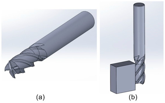
Figure 1.
CAD model of milling cutter tool (a) milling tool; (b) milling tool and workpiece.
The first cutter is polished, and the second cutter is coated with a borox coating (titanium diboride). Borox is a coating used in the processing of aluminum and magnesium alloys. The coating is light gray color, is applied to the tool in a single 1–3 µm thick layer, and can withstand temperatures up to 480 °C. One of the important properties of the borox coating, compared to other coatings, is its low friction factor of 0.35. The coating is also characterized by a reduced affinity for aluminum. Titanium diboride prevents the accumulation of aluminum on the tool edge and contributes to the extension of the tool’s life. The properties of titanium diboride are shown in Table 2.
Table 2.
Mechanical properties of titanium diboride.
2.2. Chemical and Mechanical Properties of Aluminum Alloy EN AW-7075
The analysis of the influence of technological and design parameters of milling cutter tools on the roughness properties of the machined surface was carried out on an aluminum alloy workpiece. This alloy, according to the European standard, is designated EN AW-7075 (AlZn5.5MgCu), and its chemical composition and mechanical properties are shown in Table 3 and Table 4.
Table 3.
Chemical composition of aluminum alloy EN AW-7075.
Table 4.
Mechanical properties of aluminum alloy EN AW-7075.
2.3. Analytical Calculation of Technological Parameters
The cutting speed, for milling cutters with design parameters according to Table 1 and workpiece material EN AW-7075, according to the recommendation of the manufacturer ZCC-CT, is vc = 250 m/min. The calculated value of the milling cutter rotation frequency is as follows:
In the following calculations, Dg is the milling tool diameter. The rotational frequency is rounded to n = 8000 min−1. The shear rate is determined according to the following expression:
where zc is the number of milling cutter teeth determined according to Table 1, fz is the feed per milling cutter tooth and, according to the manufacturer’s recommendation, the value fz = 0.0625 mm/z was adopted. By inserting the specified values into Expression (2), the shear rate is vf = 2000 mm/min.
The specific cutting force represents the force required to cut a particle with an area of 1 mm2. It depends on the geometry of the cutting tool and the workpiece material, and is determined by the following expression:
where kc1 is the material-dependent specific cutting force, hm is the average thickness of the separated particle and mc is the correction factor for the thickness of the separated particle. The average thickness of the separated particle is determined using the following expression:
where Ae is the radial width of the cutter, which according to the recommendation of the cutter tool manufacturer is 20% of the total cutter diameter (Dg). Therefore, it follows that Ae = 2 mm. Therefore, from Expression (4), we obtain hm = 0.028 mm. Given that for the selected tool γ0 = 0°, it follows from Expression (3) that kc = 5082.96 N/mm2. The required cutting power is determined using the following expression:
where Ap is the cutting depth, which according to [9] is Ap = 20 mm. From Expression (5) the required cutting power is Pc = 6.78 kW.
The calculation of the main cutting force (Fc), shear cutting force (Ff), cutting back force (Fp) and milling torque (Mc) is described in [9]. Their amounts are as follows: Fc = 1627.2 N, Ff = 1220.4 N, Fp = 650.88 N and Mc = 8.09 Nm.
3. Numerical Analysis of Milling Using the FEM
Numerical analysis of milling using the FEM was performed in Ansys Workbench 2025 (R1) [10]. The CAD model SolidWorks 2025 of the milling tool and workpiece was implemented in the Explicit Dynamics module (Figure 1b).
The cutters are made of hard metal, namely tungsten carbide. One cutter is coated with a polished coating, and the other cutter is coated with a borox coating. The tool and coating materials were added by the user in Ansys Workbench by defining the properties of density, Young’s modulus of elasticity and Poisson’s ratio (Figure 2). There was no need to describe the workpiece material by the user, because it was already in the Ansys Workbench material database.
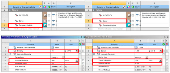
Figure 2.
Adding milling tool material and coating to Ansys Workbench.
Since the workpiece has a simple geometry, the Ansys Workbench application automatically generated a finite element mesh. Parallelepiped elements were selected for the finite elements. First-order tetrahedral finite elements were selected for the finite element mesh of the milling tool. In the contact zone of the tool and the workpiece, the finite element mesh is additionally denser and consists of elements of size 0.4 mm. The total finite element mesh consists of 107,104 elements and 40,838 nodes (Figure 3a).
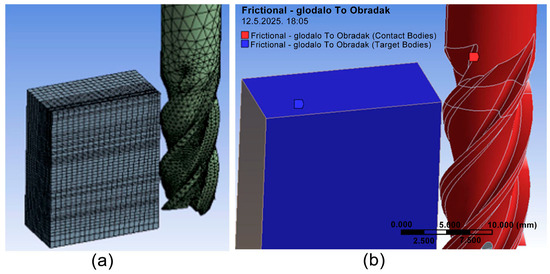
Figure 3.
Setting parameters: (a) finite element mesh; (b) friction factor on contact surfaces.
On the contact surfaces between the tool and the workpiece, a friction factor of 0.35 was defined for a milling cutter with a borox coating (Figure 3b) and 0.4 for a polished milling cutter.
In order to conduct a numerical analysis of stress and deformation for the duration of the simulation of the machining process on the milling tool and the workpiece, the duration of the simulation was defined with s and a total number of cycles. Erosion is a given effect due to the stress and material removal. In order to make the simulation of machining in Ansys Workbench possible, the yield property of the material is given.
When setting the boundary conditions, the values of the shear speeds, the main cutting forces, and the shear and back cutting forces are given with their values obtained in the analytical calculation. Before the boundary conditions, a cylindrical coordinate system is set on the milling cutter, and a Cartesian coordinate system is set on the workpiece. The first boundary condition is set on the milling cutter and defines the milling cutter displacement with respect to the number of revolutions determined according to Expression (1). The second boundary condition is set on the workpiece and defines the workpiece displacement. The defined displacement is constant and is 2000 mm/min or 33.33 mm/s.
In order to define the milling cutter coating, another finite element mesh was placed on the milling cutter. This mesh, with its element selection and density, is identical to the previously placed mesh and represents the milling cutter coating mesh. Then, the coating material and its thickness were defined. Titanium diboride was chosen as the material, and the coating thickness was 2 µm.
Figure 4 shows the maximum total deformations of both cutters. In both cases, the maximum deformation occurs at the cutter blade. The amount of the maximum deformation of the polished cutter blade is less than the amount of the maximum deformation of the cutter blade with a borox coating, 0.73 mm (Figure 4A), while the amount of maximum deformation on the cutter blade with a borox coating is 1.05 mm (Figure 4B).
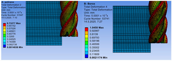
Figure 4.
Maximum total deformations: (A) polished cutter; (B) borox-coated cutter.
The equivalent Von Mises stresses are shown in Figure 5. The maximum equivalent Von Mises stresses obtained on the milling tool coated with a borox coating (Figure 5B) are significantly higher than the maximum equivalent Von Mises stresses on the milling tool with a polished edge (Figure 5A).
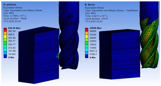
Figure 5.
Equivalent stresses according to Von Mises: (A) polished cutter; (B) borox-coated cutter.
4. Workpiece Manufacturing and Surface Roughness Analysis
Using the SolidCam 2025 SP2 software package, tool path programming and workpiece milling process simulation were performed [9]. The pre-machining of two blanks made of aluminum alloy EN AW-7075 measuring 55 × 30 × 25 mm, followed by machining, was performed on a Haas VF-2SS CNC milling machine (Haas Automation Inc., Oxnard, CA, USA), according to the technological parameters of the machining process presented in Section 2.3. of this paper. The power on the milling spindle was 22.4 kW, and the maximum speed was 12,000 min−1. The machining of the workpieces was carried out using the same machining process parameters for the polished milling cutter and the milling cutter with a borox coating.
Surface Roughness Testing
Surface roughness measurements on a workpiece machined using a polished milling cutter and a workpiece machined using a borox-coated milling cutter were performed using the MarSurf PS 10 roughness meter (Mahr GmbH, Göttingenu, Germany) (Figure 6a). This device uses the contact profilometry method (contact method) of surface roughness measurement using a needle [11]. Measurements of the arithmetic mean deviation of the profile (Ra) and the maximum profile height (Rz) were performed in the machining direction of the workpiece and in the direction perpendicular to the machining direction. In order to present the results more clearly, the directions of surface roughness measurement are indicated using a drawn Cartesian coordinate system with x and y axes (Figure 6b). The x axis determines the machining direction of the workpiece, and the y axis determines the direction perpendicular to the machining direction.
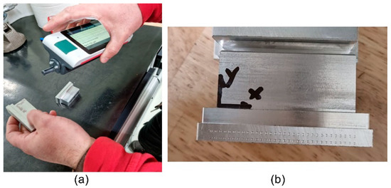
Figure 6.
Surface roughness measurement: (a) MarSurf PS 10; (b) surface roughness measurement directions.
The results of surface roughness measurements are presented in Table 5. For the polished milling cutter and milling cutter coated with borox coating, the measurement results shown for each axis are the arithmetic mean of measurements at three points on the surface in the direction of each axis.
Table 5.
Surface roughness measurement results.
The obtained measurement results show that the values of the arithmetic mean deviation of the profile (Ra) and the values of the maximum profile height (Rz) of the workpiece surface processed with a milling cutter coated with a borox coating are smaller compared to the values of the workpiece surface processed with a polished milling cutter, both in the direction of the workpiece processing and in the direction perpendicular to the processing direction. For a polished milling cutter, the values of Ra and Rz in the y-axis direction are smaller compared to the values in the x-axis direction. The same applies to the values of Ra and Rz in the y-axis direction compared to the x-axis direction for a milling cutter coated with a borox coating.
5. Conclusions
In order to contribute to a more reliable selection of appropriate tools made of appropriate materials, according to the appropriate technological parameters, this paper performed a simulation of machining using the FEM on a polished milling cutter tool and a milling cutter tool coated with borox coating. The geometric characteristics of both milling cutter tools are the same. According to the obtained numerical analysis results, when milling a workpiece made of aluminum alloy EN AW-7075, the stress values on the polished milling cutter are lower. In milling cutters with borox coating, higher stress values and deformations on the milling tool edge were obtained.
On a CNC milling machine, two workpieces were made from aluminum alloy EN AW-7075, using a milling cutter with a polished cutting surface and a milling cutter with a borox coating. Control measurements of the maximum profile height (Rz) and the arithmetic mean deviation of the profile (Ra) in the machining direction of the workpiece and in the direction perpendicular to the machining direction were made on the manufactured workpieces. The borox-coated milling cutter gave a significantly lower value of the roughness of the machined surface compared to the roughness of the machined surface of the workpiece machined with a polished milling cutter. It can be concluded that the polished milling cutter is more suitable for rough machining and removing a large amount of material from the workpiece. Contrary to the previous conclusion, the borox-coated milling cutter is suitable for fine machining and smaller milling depths.
Author Contributions
Conceptualization, T.K. and M.K.; methodology, T.K., M.K. and H.G.; software, T.K.; validation, M.K., H.G. and E.D.; formal analysis, M.K.; investigation, T.K. and M.K.; resources, T.K.; writing—original draft preparation, T.K. and M.K.; writing—review and editing, M.K., H.G., E.D. and T.K.; visualization, M.K.; supervision, M.K., E.D. All authors have read and agreed to the published version of the manuscript.
Funding
This research paper was funded by the University of Slavonski Brod through the institutional research project “Analysis of the influence of design and process parameters of FDM technology on the mechanical and vibrational properties of polyamide PA6 tooth of a cylindrical spur gear for the purpose of optimizing the hybrid infill structure design”, financed by the European Union—NextGenerationEU.
Institutional Review Board Statement
Not applicable.
Informed Consent Statement
Not applicable.
Data Availability Statement
Data are available in this manuscript.
Conflicts of Interest
The authors declare no conflicts of interest. The funders had no role in the design of the study; in the collection, analyses, or interpretation of data; in the writing of the manuscript; or in the decision to publish the results.
References
- Lokgard, M.; Grandicki, A. Parametric Cad Modeling to Aid Simulation-Driven Design an Evaluation and Improvement of Methods Used at Scania. Master Thesis, Linköping University, Linköping, Sweden, 2017. [Google Scholar]
- Zisov, H.; Milkov, D.; Cangulski, A.; Vasileska, E.; Tuteski, O.; Kusigerski, B.; Caloska, J. Effect of longitudinal and cross feed on flatness and surface roughness in flat Grniding. Adv. Eng. Lett. 2025, 4, 14–20. [Google Scholar] [CrossRef]
- Šavar, Š. Obrada Metala Odvajanjem Čestica, 1st ed.; Školska knjiga: Zagreb, Croatia, 1990; Volume 1, pp. 1–194. [Google Scholar]
- Ersvik, E.; Khalid, R. Milling in Hardened Steel—A Study of Tool Wear in Conventionaland Dynamic Milling. Master Thesis, Uppsala Universitet, Uppsala, Sweden, 2015. [Google Scholar]
- Kovač, P.; Savković, B.; Dudić, B. Modeling of cutting force relationship as a function of cutting conditions and tool wear. Adv. Eng. Lett. 2025, 4, 31–36. [Google Scholar] [CrossRef]
- BAS Engineering Solutions. Available online: https://bspengineering.co.uk/2024/04/10/how-to-use-a-cnc-machine-for-reverse-engineering/ (accessed on 10 April 2024).
- Čakić, Z. Alati za Glodanje. Bachelor’s Thesis, University of Applied Sciences, Karlovac, Croatia, 2016. [Google Scholar]
- Jakovac, F. Karakterizacija PACVD Prevlake na Tvrdom Metalu. Master’s Thesis, Faculty of Mechanical Engineering and Naval Architecture, Zagreb, Croatia, 2016. [Google Scholar]
- Kolmanić, T. Analiza Konstrukcijskih i Tehnoloških Parametara na Primjeru Alata Glodala. Master’s Thesis, University North, Varaždin, Croatia, 2022. [Google Scholar]
- Ansys Workbench. Available online: https://www.ansys.com/products/ansys-workbench (accessed on 12 May 2025).
- Zintilon. Available online: https://www.zintilon.com/blog/surface-roughness-guide/ (accessed on 30 May 2025).


Disclaimer/Publisher’s Note: The statements, opinions and data contained in all publications are solely those of the individual author(s) and contributor(s) and not of MDPI and/or the editor(s). MDPI and/or the editor(s) disclaim responsibility for any injury to people or property resulting from any ideas, methods, instructions or products referred to in the content. |
© 2026 by the authors. Licensee MDPI, Basel, Switzerland. This article is an open access article distributed under the terms and conditions of the Creative Commons Attribution (CC BY) license.