


Abstract
Methane cracking has emerged as a promising route for sustainable hydrogen production because it avoids direct carbon dioxide emissions while simultaneously enabling carbon sequestration in the form of solid carbon. In this work, a comprehensive and systematic experimental investigation of catalytic methane cracking was performed by directly comparing a commercial nickel catalyst (KATALCO™ 25-4MQ), an in-house catalyst prepared by wet impregnation using Fe(NO3)3·9H2O as the iron precursor and Puralox SCFa-160 Ce20 as the support, and non-catalytic thermal conditions under identical operating parameters. Experiments were carried out in a laboratory-scale fixed-bed reactor at atmospheric pressure by varying methane partial pressure (0.1–0.2 atm) and operating temperature (600–800 °C), while maintaining a constant methane-specific WHSV of 0.3 h−1. Continuous online gas analysis was employed to monitor reactor performance, and a dedicated post-processing methodology, including nitrogen-tracer-based carbon balance calculations, was developed to validate the experimental results. The results demonstrated the strong beneficial effects of both temperature and catalytic materials on methane decomposition. The Fe-based catalysts exhibited the highest performance, achieving average methane conversions and hydrogen yields approaching 50%, with peak values exceeding 90% under the most favorable conditions. Commercial Ni catalysts also showed promising activity, although a more pronounced deactivation tendency was observed during prolonged operation. Conversely, non-catalytic tests resulted in substantially lower performance. Overall, this work provides an experimentally assessed and integrated methodology together with benchmark performance indicators that may serve as useful guidance for researchers, process designers, and practitioners involved in the development, optimization, and future scale-up of methane cracking technologies for turquoise hydrogen production.
1. Introduction
Hydrogen is widely recognized as one of the key pillars of the global energy transition due to its potential to decarbonize sectors that are difficult to electrify, including heavy industry, long-haul transportation, and high-temperature industrial processes [1,2,3]. Growing concerns regarding climate change, energy security, and greenhouse gas emissions (37.4 Gt in 2023 [4]) have stimulated considerable interest in the development of sustainable hydrogen production pathways. According to the International Energy Agency (IEA), hydrogen demand is expected to increase substantially in the coming decades, supporting the achievement of global carbon neutrality targets and reinforcing the strategic role of hydrogen in future energy systems [3]. Depending on the route taken for decarbonization, worldwide hydrogen consumption is projected to rise from roughly 95 million metric tons in 2022 to more than 500 million metric tons in 2050.
Currently, most hydrogen is produced from fossil resources, primarily through steam methane reforming (SMR) and coal gasification [1,5].
Although these technologies are mature and economically competitive, they are associated with significant carbon dioxide emissions. According to recent estimates, these technologies are responsible for nearly 900 Mt of CO2 per year [6]. The implementation of carbon capture and storage (CCS) technologies can partially mitigate these emissions, leading to so-called “blue hydrogen” [7]. However, concerns remain regarding capture efficiency, long-term storage reliability, additional energy requirements, and overall process economics [8,9]. Alternatively, water electrolysis powered by renewable electricity represents a near-zero-carbon route for hydrogen production. To reach net-zero by 2050, electrolysis deployment must approach 3600 GW [10]. At the same time, renewable energy continues to grow at an accelerating pace. By way of reference, the WBA reports that bioenergy provides about 55 EJ per year—representing some 10% of the world’s primary energy [11].
Despite its environmental advantages (1.539 kgCO2 kgH2−1 [10]), the large-scale deployment of green hydrogen is still constrained by the high cost of renewable electricity, intermittency issues, and the substantial capital investment required for electrolyzer systems [10,12,13].
Besides electrolysis, significant research efforts have been devoted to alternative sustainable hydrogen production routes, including biomass conversion technologies and membrane-assisted processes [14]. Biomass-derived hydrogen represents a promising renewable pathway capable of valorizing agricultural residues and organic waste while contributing to greenhouse gas emission reduction targets [5,13]. In addition, membrane reactors have been extensively investigated as an effective approach to improve hydrogen production efficiency, enhance reaction yields through selective hydrogen removal, and intensify thermochemical conversion processes [15]. These approaches are increasingly integrated within circular economic frameworks, where waste valorization and resource efficiency play a central role in achieving sustainable industrial development [16,17].
Within this framework, methane cracking has emerged as a promising alternative technology capable of producing hydrogen without direct carbon dioxide emissions during the conversion process. Methane cracking represents a potentially low-carbon hydrogen production route because it intrinsically avoids direct process CO2 formation by converting methane into hydrogen and solid carbon. It offers potential environmental benefits depending on methane origin, energy supply, and the subsequent management and utilization of the produced solid carbon. The resulting hydrogen, commonly referred to as “turquoise hydrogen”, has attracted increasing attention as a potential intermediate solution between conventional fossil-based hydrogen production and fully renewable hydrogen systems [18,19,20,21,22]. Recent reviews have highlighted significant advances in catalyst development, reactor design, process intensification, and techno-economic assessment, confirming the growing interest in methane cracking as a low-carbon hydrogen production pathway [21,22]. Unlike conventional reforming technologies, methane cracking generates solid carbon rather than gaseous carbon oxides, potentially reducing the complexity and cost associated with carbon capture and storage. Furthermore, depending on catalyst composition and operating conditions, the solid carbon produced may find applications in several industrial sectors, including carbon black manufacturing, advanced carbon materials, batteries, supercapacitors, and composite materials [19,20,21,22].
Despite these advantages, several technical challenges still hinder the large-scale implementation of methane cracking technologies. The process is thermodynamically favored only at relatively high temperatures, resulting in substantial energy requirements [16]. Moreover, catalyst deactivation caused by carbon deposition remains one of the major obstacles to achieving stable and economically viable operation. Carbon accumulation on active sites can progressively reduce catalyst activity, limiting methane conversion and hydrogen productivity during extended operation [23,24]. Consequently, the identification of catalytic materials capable of combining high activity with long-term stability represents a critical research priority for the development of industrial methane cracking processes.
Among the various catalytic systems investigated, nickel-based catalysts have received significant attention due to their excellent methane activation capability, widespread availability, and relatively low cost compared with noble metals [25,26,27]. Numerous studies have demonstrated that nickel catalysts can achieve high methane conversion and hydrogen yields at temperatures significantly lower than those required for non-catalytic methane decomposition [25,26,27]. However, their practical application is often constrained by rapid deactivation associated with carbon deposition, sintering phenomena, and structural modifications occurring under reaction conditions [28,29].
Iron-based catalysts have emerged as a promising alternative due to their lower cost, environmental compatibility, and improved resistance to deactivation [30,31]. Although generally characterized by lower intrinsic catalytic activity than nickel-based systems, iron catalysts frequently exhibit enhanced durability and greater tolerance toward carbon formation, particularly under prolonged operating conditions [30,31]. In addition, iron-containing catalysts have demonstrated the ability to promote the formation of filamentous carbon structures that can partially preserve catalyst accessibility and reduce pore blockage phenomena [32]. As a result, iron-based materials are increasingly considered attractive candidates for sustainable methane cracking applications.
An additional aspect contributing to the growing interest in methane cracking is the potential valorization of the solid carbon co-product. Unlike carbon dioxide generated in conventional reforming processes, solid carbon can be recovered, handled, transported, and potentially utilized in a variety of industrial applications. Depending on catalyst composition and operating conditions, methane cracking may yield carbon materials with different morphologies and properties, including carbon black, filamentous carbon, carbon nanofibers, and graphitic structures [19,20,21]. The possibility of integrating hydrogen production with carbon valorization pathways may significantly improve process economics while reducing the overall environmental footprint. Consequently, methane cracking is increasingly regarded not only as a low-carbon hydrogen production technology but also as a potential platform for the development of integrated carbon utilization value chains within future circular and zero-waste industrial systems [16,19,20,21,22].
Several recent investigations have explored the performance of nickel- and iron-based catalysts for methane cracking, highlighting the inherent trade-off between catalytic activity and operational stability [33,34,35,36,37]. Recent reviews have further emphasized the need for comparative studies performed under identical operating conditions to facilitate catalyst screening, improve process understanding, and support future scale-up activities [21,22,37]. Nevertheless, direct comparisons between commercial nickel- and iron-based catalysts under the same operating conditions remain relatively limited in the available literature. Differences in catalyst formulation, reactor configuration, feed composition, and operating parameters often make it difficult to establish clear performance benchmarks and identify the most suitable catalyst systems for industrial implementation.
Work and Contribution
Despite the extensive literature available on catalytic methane cracking, direct comparisons among different catalyst families remain difficult because experimental investigations are frequently conducted under substantially different operating conditions, including variations in reactor configuration, catalyst loading, methane concentration, residence time, and post-processing methodologies. Consequently, establishing reliable performance benchmarks and identifying suitable catalyst systems for future industrial implementation remain challenging.
In this context, the present work proposes a systematic and integrated experimental methodology for the assessment of methane cracking technologies from a hydrogen production perspective. The originality of the study does not rely solely on the investigated catalytic materials themselves but rather on the development of a comprehensive framework capable of simultaneously evaluating methane conversion, hydrogen productivity, catalyst stability, and carbon balance closure under fully comparable operating conditions.
Specifically, commercial nickel catalysts, in-house synthesized Fe/CeO2–Al2O3 catalysts, and purely thermal methane cracking were investigated under identical reactor configurations, methane feed rates, and operating procedures. The experimental campaign involved a substantial number of long-duration tests, enabling the generation of a validated dataset suitable for identifying catalyst performance trends and performance decay mechanisms.
Furthermore, the proposed methodology integrates:
- ▪
- Standardized catalyst activation procedures;
- ▪
- Continuous online gas analysis;
- ▪
- Validated carbon balance calculations using nitrogen as an inert tracer;
- ▪
- Systematic post-processing of experimental data;
- ▪
- Comparative assessment of catalyst activity.
The resulting framework provides practical guidelines for catalyst screening and selection, enabling the identification of suitable materials and operating conditions for methane cracking applications.
Beyond the immediate experimental findings, the generated dataset constitutes a valuable basis for future developments, including kinetic modeling, reactor design, process intensification, scale-up studies, and techno-economic analyses accounting for both hydrogen production and carbon valorization pathways.
Therefore, the main original contribution of this work consists of establishing an experimentally validated and reproducible methodology for the comparative assessment of methane cracking technologies, while simultaneously providing benchmark performance indicators and practical recommendations for the future development of turquoise hydrogen production systems.
In addition, the methodology proposed in this work may serve as a general framework for future investigations on methane cracking, allowing different catalyst formulations and reactor concepts to be assessed on a common basis. Such standardization is particularly important because the absence of harmonized experimental procedures currently represents one of the main obstacles to the comparison of literature results and to the identification of optimal catalyst systems for industrial deployment.
2. Materials and Methods
2.1. Theory and Calculations
Methane cracking, also referred to as methane pyrolysis, is an attractive route for hydrogen production because it avoids direct carbon dioxide emissions, while simultaneously promoting the formation of solid carbon, which is inherently separated from the gaseous phase owing to its deposition within the reactor and on the catalyst surface. The overall reaction can be expressed as reported in (1).
Although methane cracking is thermodynamically a reversible reaction, the operating conditions investigated in this work (as will be seen later: 600–800 °C, absence of oxidizing species, and progressive separation of carbon as a solid phase) considerably shift the equilibrium toward hydrogen and solid carbon formation. Consequently, reverse methanation and carbon gasification reactions were assumed to be negligible.
Under these boundaries, the reaction is mildly endothermic, with a standard enthalpy change equal to , compared with steam methane reforming, which requires approximately 206 kJ mol−1.
The thermodynamic equilibrium of methane cracking shifts toward hydrogen formation as temperature increases. However, because of the high dissociation energy of the C–H bond (approximately 439 kJ mol−1), significant methane conversion under non-catalytic conditions generally requires temperatures above 1000–1200 °C.
Methane conversion—Methane conversion is calculated from inlet and outlet methane concentrations measured by the online gas analyzer, as illustrated in (2).
where and are the molar flow rates of methane entering and leaving the reactor, respectively.
Hydrogen yield—Hydrogen yield is evaluated according to the stoichiometric maximum production obtainable from methane decomposition, as in (3).
Here, the denominator accounts for the theoretical production of two moles of hydrogen per mole of methane converted.
Carbon yield—The carbon yield may be estimated with Equation (4), assuming that all carbon generated remains in the solid phase.
Figure 1 illustrates the overall methane cracking process together with the methodology adopted for the determination of the carbon balance and the associated relative error. As will be observed, methane is fed to the reactor together with nitrogen, which is employed as an inert tracer gas owing to its chemical stability and non-participation in the cracking reactions. Assuming complete conservation of nitrogen throughout the process, the total outlet molar flow rate can be determined from the measured outlet gas composition. Subsequently, the molar and mass flow rates of the individual gaseous species (CH4, H2 and N2) are calculated. Since methane is the sole carbon-containing species at the reactor inlet and carbon monoxide or carbon dioxide are not detected in appreciable amounts during such experiments, the carbon balance can be established by considering the carbon remaining in the unconverted methane and the carbon deposited inside the reactor as solid carbon (due to cracking).
Figure 1.
Schematic representation of the methane cracking process and methodology adopted for the calculation of the carbon balance and associated relative error using nitrogen as an inert tracer gas (The term indicates the solid carbon formed and deposited inside the reactor and on the catalyst surface, whereas refers to the carbon remaining in the gaseous phase, as unconverted methane; The total outlet carbon flow used in the carbon balance is therefore expressed as ).
The comparison between the inlet carbon flow and the sum of gaseous and deposited carbon enables the estimation of the relative carbon balance error. This procedure provides an important validation tool for assessing the reliability of the experimental measurements and the consistency of the calculated methane conversion and hydrogen yield values.
It should be emphasized that no dedicated carbon separation unit was employed in the present experimental setup. The term “carbon separation” refers exclusively to the phase transformation occurring during methane cracking, where carbon is generated as a solid product and therefore becomes naturally separated from the gaseous stream. Most of the produced carbon remains deposited inside the reactor and on the catalyst particles. Consequently, denotes the mass of carbon deposited during the experiment, whereas represents the carbon still leaving the reactor in gaseous form, mainly associated with unconverted methane. The total outlet carbon flow used in the carbon balance is therefore expressed as .
Outlet molar flow rates—The outlet molar flow rates were determined using nitrogen as an inert internal tracer. Assuming nitrogen conservation throughout the reactor (5).
The portable gas analyzer used in this study does not include a dedicated nitrogen detector. Instead, it provides the nitrogen mole fraction as a software-calculated value based on the measured dry-gas composition. The total dry outlet molar flow rate () was therefore calculated as in (6) accordingly.
where is the inlet nitrogen molar flow rate determined from the controlled inlet gas flow, and is the analyzer-generated nitrogen mole fraction automatically computed and displayed by the instrument.
The outlet molar flow rate of each gaseous species () was subsequently determined according to (7).
where is the mole fraction of species (CO, CO2, CH4, higher hydrocarbons, H2, O2) directly measured by the gas analyzer.
Because is not directly measured but is instead calculated by the analyzer from the measured gas composition; it does not represent an independent analytical measurement. The corresponding outlet flow and performance indicators are therefore based on the analyzer-generated nitrogen value.
Other KPIs (mass-based indicators)—Specific hydrogen production () and specific carbon production () are calculated as in (8) and (9).
where is the specific hydrogen production, expressed as kg H2 per kg CH4 fed. The factor 2 accounts for the stoichiometric formation of two moles of hydrogen per mole of methane according to the methane cracking reaction.
where is the specific carbon production, considering that all converted methane is assumed to form solid carbon.
Weight hourly space velocity—In the catalytic methane cracking tests, the operating conditions were expressed in terms of weight hourly space velocity (WHSV), defined as the methane mass flow rate () per unit mass of catalyst (), as reported in (10).
For the purposes of this study, WHSV was selected as the primary operating parameter to ensure a consistent basis for comparing the performance of different catalytic systems under controlled methane feeding conditions. The methane mass flow rate was kept constant, while the nitrogen flow was adjusted to obtain the target methane partial pressure. Hence, the analysis focused on the effect of methane partial pressure while maintaining identical methane-specific feed rates to the catalyst.
Accordingly, WHSV was calculated considering only the methane feed, as it represents the reacting species. Keeping the methane WHSV constant ensured that each catalyst was exposed to the same methane mass flow per unit catalyst throughout the experiments, enabling a direct and meaningful comparison of catalytic performance. As anticipated, nitrogen was employed as an inert diluent to adjust the methane partial pressure and was therefore not included in the WHSV calculation. Variations in nitrogen flow rate changed the total gas flow rate and therefore affected GHSV (Q/Vr), superficial velocity, and residence time. For this reason, the observed trends should be interpreted as the combined effect of feed dilution and hydrodynamic conditions rather than as the isolated effect of methane partial pressure. Variations in nitrogen flow rate inherently modify the total gas flow rate, influencing parameters such as GHSV and residence time. These variations are a direct consequence of adjusting the methane partial pressure via dilution while preserving a constant methane-specific operating condition.
A blank (non-catalytic) test was performed as a reference for assessing the intrinsic contribution of the catalyst to methane conversion and hydrogen production. The blank experiment was performed without catalysts to quantify the reactive background of the system, including any wall effects and thermal cracking reactions.
The WHSV adopted in the catalytic tests was 0.3 h−1, in line with values commonly reported in laboratory-scale methane cracking studies. For example, Mirkarimi et al. [38] indicate that temperatures above 800 °C combined with relatively low space velocities (below 1 L g−1 h−1 for pure methane) are generally required to achieve methane conversions exceeding 50%.
Background on Reaction Mechanisms and Kinetic Interpretation
Three different methane cracking processes are investigated in this work, namely, catalytic decomposition over a commercial nickel catalyst, catalytic decomposition over an in-house developed iron-based catalyst, and non-catalytic thermal decomposition.
The detailed mechanism of methane cracking is extremely complex and involves adsorption, dissociation, hydrogen desorption, carbon nucleation, and carbon diffusion phenomena. The following kinetic expressions are reported solely to provide the theoretical background commonly adopted in the literature for describing methane cracking under thermal and catalytic conditions. The present work does not aim to determine intrinsic kinetic parameters, activation energies, or reaction orders (since this is beyond the scope of the paper). Rather, these formulations are introduced to facilitate the interpretation of the experimental observations and to qualitatively explain the different behaviors observed for nickel- and iron-based catalysts.
Non-catalytic methane cracking—Under purely thermal conditions, methane decomposition can be described by a first-order Arrhenius-type expression [39], as reported in (11) and (12), where is the methane partial pressure, and other parameters have known meanings.
Typical activation energies reported for thermal methane decomposition range between 240 and 400 kJ mol−1, explaining the need for very high temperatures.
Nickel-catalyzed methane cracking—For nickel catalysts, methane cracking generally follows Langmuir–Hinshelwood kinetics, where methane adsorption and surface reactions occur on metallic Ni active sites.
A commonly adopted expression is (13), where is the apparent rate constant; is the hydrogen adsorption constant; is the methane partial pressure; is the hydrogen partial pressure [40].
The temperature dependence follows Arrhenius behavior, as in (14).
Nickel catalysts exhibit high activity at temperatures between 600 and 800 °C, although catalyst deactivation due to carbon deposition remains a major limitation.
Iron-catalyzed methane cracking—The iron catalyst employed in this study consists of Fe species dispersed over a CeO2-Al2O3 support. Following reduction, metallic Fe active sites catalyze methane decomposition according to the simplified model [41], reported in (15).
In the equation, n is the apparent reaction order, generally approaching a near unity number, with respect to methane concentration, generally reported in the literature within the range of approximately 0.5–1, depending on catalyst formulation and operating conditions. The Arrhenius equation remains valid: . Previous studies have suggested that the presence of CeO2 may improve oxygen mobility and redox properties, while Al2O3 provides a high-surface-area support, enhancing metal dispersion and partially mitigating catalyst deactivation phenomena.
2.2. Test Rig Configuration
Figure 2 illustrates the experimental apparatus employed for methane cracking tests. The experimental setup consists of a fixed-bed continuous-flow stainless steel reactor electrically heated by an external thermocontrolled furnace. Methane and nitrogen are supplied from dedicated gas cylinders equipped with pressure regulators and needle valves to control the inlet flow rates and adjust the desired methane partial pressure.
Figure 2.
Test rig configuration.
The reactor temperature is controlled through an electric heating system operating within the range of 600–800 °C for this specific scope.
The methane cracking experiments were carried out in a tubular fixed-bed reactor made of stainless steel, consisting of a straight vertical tube with an internal diameter of 2.5 cm. The catalytic bed was obtained by stacking the catalyst particles inside the tube, and its height varied according to the amount of catalyst loaded to reach the desired mass. Two catalyst morphologies were employed in this work: nickel-based cylindrical pellets, which were loaded as stacked cylinders to form the packed bed, and an iron-based catalyst in the form of tabs, which were loaded as regular particles. The characteristics of the catalysts are described in Section 2.4. Catalyst preparation and activation. In both cases, the total bed height in the reactor depended on the catalyst mass introduced and thus differed between experiments carried out with nickel cylinders and those carried out with iron tabs. Approximately 17 g of catalyst was loaded for each experiment, corresponding to the selected methane-based WHSV of 0.3 h−1.
The catalyst bed is positioned at the center of the reactor-furnace to ensure uniform temperature distribution.
The gaseous products exiting the reactor are continuously monitored by an online gas analyzer connected to a computer-based data acquisition system for real-time recording and processing of the experimental data.
According to the scheme shown in Figure 2, the setup therefore comprises four main subsystems:
- Gas feeding section;
- Thermocontrolled fixed-bed reactor;
- Electrical heating and temperature control system;
- Online gas analysis and data acquisition system.
2.3. Experimental Settings
Methane cracking tests are conducted by varying methane partial pressure and reaction temperature while comparing two catalytic formulations with purely thermal conditions. The feed consists of methane diluted in nitrogen. Methane flow rate is maintained constant throughout the campaigns, whereas nitrogen flow is adjusted to obtain the desired methane partial pressure.
The investigated operating conditions are summarized in Table 1.
Table 1.
Settings and operating conditions.
The present experiments are performed at a WHSV of approximately 0.3 h−1, favoring longer residence times and enhanced methane conversion. The adopted value falls within the lower range commonly reported for methane cracking processes. CH4 flow was kept constant, whereas N2 was varied to set the desired CH4 partial pressure. This changed the total flow rate almost twofold, so GHSV and residence time also changed. The observed trend should therefore be interpreted as a combined effect of dilution and hydrodynamics, not as a pure partial-pressure effect.
Effect of pressure: All methane cracking experiments were performed at atmospheric pressure. The reactor was equipped with a pressure transmitter that continuously monitored the operating pressure throughout each experimental run. As carbon progressively accumulated inside the reactor and downstream tubing, a slight pressure increase was occasionally observed. However, this increase remained limited and did not produce reactor blockage or unstable reactor operation under the investigated operating conditions.
2.4. Catalyst Preparation and Activation
2.4.1. Commercial Nickel Catalyst
KATALCO™ 25-4MQ is a nickel-based catalyst supported on calcium aluminate, lightly alkalized with potassium, presenting a QUADRALOBE pellet geometry, whose image is shown in Figure 3 [42]. Its main properties are reported below.
Figure 3.
KATALCO 25-4MQ.
- -
- Active metal: nickel oxide (NiO) finely dispersed on a ceramic calcium aluminate support.
- -
- Typical NiO content (25-series): about 18 wt%.
- -
- Alkaline promoter: K2O (“lightly alkalized”), approximately 1.8 wt%, which increases the margin against carbon formation and accelerates its removal during operation and steaming cycle.
- -
- Controlled impurities: very low silica (≈1.5 wt% SiO2) and sulfur (≈0.05 wt% as SO3), in order to minimize silica migration phenomena and catalyst poisoning.
Shape: QUADRALOBETM pellet (cylindrical, 4-hole, 4 external flutes, domed edges).
Length: 13 mm. External diameter: 10.5 mm. Internal hole diameter: 2.7 mm. Typical loaded bulk density: ~950 kg/m3.
The QUADRALOBE geometry is designed to combine high catalytic activity (large external surface area, favorable internal gas flow) with low pressure drop and excellent tube wall–gas heat transfer, which is particularly critical near the tube outlet but also beneficial at the inlet to control tube wall temperatures.
Before methane cracking experiments, the KATALCO™ 25-4MQ catalyst bed was subjected to a preliminary activation step in pure hydrogen. The catalyst was heated to 400 °C under flowing H2 and maintained at this temperature for a sufficient time to promote the reduction of a significant fraction of the NiO phase dispersed on the calcium aluminate support [43]. The effectiveness of this activation step was confirmed by the immediate onset of methane conversion, hydrogen formation and solid carbon deposition once CH4 was introduced, indicating that a catalytically active Ni phase had been generated under these reduction conditions.
2.4.2. Nickel Catalyst Characterization
The KATALCO 25-4MQ catalyst, consisting of lightly alkalized nickel on a calcium aluminate support, is designed to operate under more severe conditions, particularly in the inlet section of the tube, where the risk of carbon laydown is higher. In this context, post-reaction deactivation is mainly attributed to carbon deposition on the active surface and within the support porosity, with different effects on catalytic functionality. Alkali promotion increases resistance to coke formation and facilitates its removal during steaming, but it does not completely prevent activity loss due to pore blockage and progressive coverage of nickel sites [42,44,45].
A comprehensive post-reaction characterization of spent Ni/CaAl2O4 catalysts is essential to clarify the deactivation pathways and assess the operational stability of the system. Thermogravimetric analysis is particularly useful for quantifying the total carbon deposit, since controlled oxidation of the spent catalyst allows the amount of coke to be measured directly and, in many cases, enables a distinction between less ordered carbon species and more structured filamentous carbon based on their oxidation behavior. X-ray diffraction provides complementary information on the metallic phase, allowing changes in Ni crystallite size to be estimated and potential sintering phenomena to be detected through peak broadening analysis [46]. In addition, SEM and TEM offer direct evidence of the morphology and spatial distribution of the deposited carbon, making it possible to identify carbon nanofilaments, nanotubes, and encapsulating shells around nickel particles.
Although these characterization analyses were not directly performed in this work, the interpretation of catalytic performance and deactivation behavior strongly suggests that similar mechanisms are occurring under the investigated conditions, in agreement with what is widely reported in the literature for Ni-based catalysts.
Encapsulation of the active particles by more ordered carbon leads to a more pronounced and essentially irreversible deactivation, whereas the accumulation of filamentous or amorphous carbon within the pores mainly causes diffusion limitations and an increase in pressure drop. Consequently, the residual catalytic performance depends not only on the total amount of coke but also on its morphology and distribution within the catalyst bed: filamentous structures may coexist with a reasonable residual activity, while more compact or encapsulating deposits can rapidly degrade performance. From the deactivation mechanism perspective, two main phenomena can therefore be distinguished: encapsulation of the active particles and pore plugging of the support. Encapsulation occurs when carbon, often more ordered and graphitic in nature, surrounds the nickel particles and isolates the active surface from the reactants; this mechanism is generally associated with a marked and poorly reversible loss of activity and can be readily identified by TEM through the presence of compact carbon shells around the metal particles. Pore plugging, on the other hand, results from the accumulation of amorphous or filamentous carbon in the interparticle voids and within the support porosity, leading to increased diffusional resistance and pressure drop; in this case, performance decay may be more gradual and, to some extent, recoverable by controlled oxidation of the carbon deposit.
The correlation between residual activity and coke amount is not linear, since the total carbon mass does not fully describe the impact on catalyst functionality [47]. Extensive filamentous carbon deposits may coexist with a moderate loss of performance, because filaments often tend to grow away from the formation site without immediately choking it; by contrast, even limited amounts of compact, graphitic, or encapsulating carbon can cause a rapid decline in activity by blocking access to nickel sites. In practical terms, this means that the catalyst may still show a reasonable residual conversion despite a high coke content or, conversely, a strong deactivation even with a relatively small but unfavorably distributed deposit.
2.4.3. Preparation of the Fe/CeO2-Al2O3 Catalyst
The catalyst was prepared by wet impregnation using Fe(NO3)3·9H2O as the iron precursor and Puralox SCFa-160 Ce20 as the support. The support is a ceria-doped alumina material composed of 81.5% Al2O3 and 18.5% CeO2, supplied in tablet form with a mean diameter of 3.08 mm and a mean length of 3.14 mm. Its textural and mechanical properties include a specific surface area of 158 m2/g, a total pore volume of 0.505 mL/g, a packed bulk density of 0.84 g/mL, and a crush strength of 13 N [48]. Figure 4 illustrates the stage of preparation.
Figure 4.
Catalyst preparation of the iron-based catalyst.
Wet impregnation was selected because the targeted iron loadings (2.5 and 5 wt%) were below the threshold generally considered suitable for precipitation methods (15–20 wt%). Under these conditions, precipitation may promote rapid nucleation and growth within the bulk solution, resulting in non-uniform deposition concentrated on the external surface of the support particles.
The preparation procedure involved four sequential steps:
(i) Impregnation. The support was contacted with the iron nitrate solution for a predetermined time to promote precursor diffusion and homogeneous distribution.
(ii) Drying. Excess solvent was removed using a rotary evaporator operating at approximately 70 °C and 150 mbar.
(iii) Calcination. The dried catalyst was calcined in air at 600–650 °C for 4 h. This treatment removed residual volatile compounds, converting iron nitrate into iron oxides (thus generating the iron oxide precursor phases), and stabilized the mechanical properties of the support. The selected calcination temperature was supported by preliminary thermogravimetric analysis of the CeO2-Al2O3 support.
(iv) Reduction. Prior to the reaction, the calcined catalyst was activated under a hydrogen atmosphere to reduce iron oxides into catalytically active metallic iron species. Reduction was performed at 600 °C under a hydrogen flow of approximately 2 g h−1 for about 2 h.
The preparation methodology and activation conditions were selected according to literature procedures reported by Yang et al. [49] and Yan et al. [50], which demonstrated that Ce-promoted Fe catalysts exhibit enhanced redox properties, improved metal dispersion, and superior catalytic stability during methane cracking.
Detailed physicochemical characterization of the synthesized Fe(NO3)3·9H2O/Puralox Ce20 catalyst before and after methane cracking was not experimentally performed due to the temporary unavailability of advanced characterization facilities. Nevertheless, the expected catalyst evolution can be inferred from previous investigations reported in the literature on similar Fe-based systems.
In particular, Yan et al. [50] extensively characterized Fe2O3-derived catalysts under methane decomposition conditions by means of XRD, FTIR and thermogravimetric analyses. Since the catalyst employed in the present work is also based on iron oxides dispersed over an alumina–ceria support, these results provide useful indications regarding the possible structural transformations occurring during the reaction.
2.4.4. Fe/CeO2-Al2O3 Catalyst—Characterization Before Reaction
Prior to reaction, the catalyst is expected to consist predominantly of highly dispersed Fe2O3 species supported on γ-Al2O3 and CeO2 phases [50]. The addition of ceria is known to increase oxygen storage capacity, improve iron dispersion and enhance metal–support interactions. Similar catalysts generally exhibit hematite diffraction peaks together with broad alumina reflections and CeO2 fluorite peaks in XRD analyses.
Furthermore, CeO2 may generate oxygen vacancies capable of facilitating methane activation and reducing catalyst deactivation phenomena.
2.4.5. Fe/CeO2-Al2O3 Catalyst—Characterization After Reaction
After methane cracking at 600–800 °C, substantial catalyst restructuring is expected. Based on literature findings [50], methane acts as a reducing agent, promoting the progressive transformation:
Fe2O3 → Fe3O4 → FeO → Fe0 → Fe3C
The formation of metallic Fe and iron carbide phases is generally accompanied by the deposition of graphitic or turbostratic carbon species.
Iron carbide (Fe3C) has frequently been identified as one of the catalytically active phases during methane decomposition and hydrogen generation. Simultaneously, carbon filaments or carbon nanotube structures may nucleate on metallic iron particles.
In the present catalyst, the presence of CeO2 in the Puralox Ce20 support is expected to enhance oxygen mobility and improve dispersion of iron particles, partially mitigating sintering and carbon encapsulation phenomena. Consequently, the catalyst may preserve catalytic activity for longer times compared with conventional Fe2O3-Al2O3 formulations.
Considering the operating temperatures employed in this work (600–800 °C), the catalyst operating at 800 °C is expected to exhibit a higher degree of reduction and a larger fraction of Fe3C and graphitic carbon species than the catalyst operated at 600 °C.
2.5. Gas Analysis
The composition of the gaseous products generated during methane cracking is continuously monitored using an online gas analysis system connected downstream of the reactor. The reactor effluent is directed to the analyzer after appropriate conditioning to ensure stable operating conditions and minimize potential interferences associated with temperature fluctuations, moisture, or particulate matter.
The specific characteristics of the analytical instrument, including the detection principle, measurable species, analytical ranges, and measurement uncertainty, are reported together with the model and manufacturer details of the gas analyzer employed in the experimental setup. The gaseous products generated during the experimental campaigns are analyzed using a GEIT 3100 portable gas analyzer (Pollutek Gas Analysis, Pellenberg, Belgium), specifically designed for online monitoring of process streams. This instrument is equipped with individual non-dispersive infrared (NDIR) detectors for carbon monoxide, carbon dioxide and methane, each operating over a measurement range of 0–100% v/v, as well as an NDIR channel for higher hydrocarbons (CnHm) in the range 0–20% v/v. Hydrogen is quantified by means of a thermal conductivity detector (TCD) with a measurement range of 0–100% v/v, while oxygen is measured using an electrochemical detector (ECD) covering the range 0–25% v/v. According to the manufacturer’s operating manual, the analyzer also calculates and displays the nitrogen concentration (N2) in real time as an internal software function. Consequently, the nitrogen concentration reported by the instrument is a software-generated parameter derived from the measured dry-gas composition and not the output of a dedicated nitrogen detector.
Prior to entering the analyzer, the gas stream is conditioned through a dedicated purification line containing silica gel, which removes water vapor by adsorption and, together with mechanical filtration, retains any entrained solid particles, thereby preventing condensation and dust deposition inside the measurement cells. The conditioned gas is then fed to the analyzer at a controlled flow rate of approximately 0.5 L/min, ensuring stable detector response and minimizing fluctuations associated with flow disturbances. The gas composition is recorded continuously, and the instrument stores averaged readings at 30 s intervals in its internal memory, providing a time-resolved profile of the outlet gas during each experimental run. At the end of each test, the complete dataset is downloaded via the proprietary acquisition software supplied with the analyzer, which is used for data export and subsequent processing.
The experimental data obtained from the gas analyzer are subsequently used to calculate methane conversion, hydrogen yield, and the other performance indicators, such as those reported in Section 2.1.
At the present stage of the research activity, a detailed physicochemical characterization of the produced solid carbon was not performed due to the temporary unavailability of the analytical instrumentation dedicated to carbon characterization, including Raman spectroscopy, SEM/TEM analyses, XRD, and elemental analyses. Nevertheless, this limitation does not affect the main objectives of the present study. Indeed, the primary scope of this work was the assessment of the feasibility of methane cracking as a route for the simultaneous production of low-carbon hydrogen and permanent carbon sequestration in the form of solid carbon, rather than the comprehensive valorization of the carbonaceous by-product itself. Consequently, the experimental campaign was principally directed toward evaluating methane conversion, hydrogen production, process monitoring, and carbon balance closure.
Planned activities will specifically address the detailed characterization of the produced carbon, including its morphology, crystallinity, graphitization degree, and potential industrial applications. Such investigations are particularly relevant because the valorization of solid carbon as a marketable by-product may substantially improve the overall process economics. In fact, revenues associated with carbon commercialization may contribute to partially offsetting both the operational and energy expenditures of the methane cracking process. Consequently, future techno-economic analyses will consider not only hydrogen production metrics but also the contribution of carbon valorization to the reduction of the specific energy consumption, the levelized cost of hydrogen (LCOH), and the overall process cost. Therefore, the simultaneous production of hydrogen and valuable carbon materials may further enhance the attractiveness and sustainability of methane cracking technologies.
3. Results and Discussion
As anticipated, the experimental campaign comprised tests performed under different operating conditions, including variations in methane partial pressure, reaction temperature, and catalyst formulation. The adopted post-processing procedure consisted of collecting the experimental measurements from the gas analysis system, recording the resulting datasets through the acquisition software, and subsequently importing the raw data into a dedicated mathematical environment for further elaboration. The acquired signals were processed to calculate the relevant performance indicators, including methane conversion and hydrogen yield, which are subsequently represented in graphical form to facilitate interpretation of the reactor behavior and comparison among the investigated operating conditions.
The experimental campaign was conducted over an extended period due to the large number of operating conditions investigated. Each experimental test required a dedicated day to prepare the setup, set the operating conditions, conduct the experiment, verify the process parameters, and ensure the correct acquisition and storage of the measured data. The subsequent post-processing activities were performed separately, only after the completion and validation of each experimental run.
Regarding the presentation of the results, it was deemed appropriate to use ‘sample time’ on the x-axis. Each sample corresponds to a time interval of 30 s, and is the same for all tests. Time-on-stream could also be used; however, because of the constant acquisition interval and the large number of data points, the sample number representation was retained to improve figure readability and maintain homogeneous formatting among all experimental campaigns. The experimental campaign results in an overall duration of 10–140 min for each test (depending on the operating condition and catalyst behavior). The sample number is directly proportional to the elapsed experimental time according to .
The validated datasets were processed to calculate the relevant performance indicators, such as: molar outlet compositions, methane conversion, hydrogen yield and carbon balance. Finally, a dedicated aggregated chart reports the performance altogether to be quickly compared and assessed.
Figure 5 reports the temporal evolution of the outlet gas composition for all methane cracking experiments. Nitrogen remained relatively constant in all tests, generally accounting for approximately 75–92 mol.%, confirming its inert behavior and validating its use as a tracer gas for the determination of total outlet flow rates and carbon balances.
Figure 5.
Outlet molar composition for all tests.
For the catalytic tests performed at 600 °C and pCH4 = 0.1 atm, hydrogen concentrations initially reached approximately 11.8 mol.%, before gradually decreasing to about 5.6 mol.%, with an average value of 6.46 mol.%. Simultaneously, the outlet CH4 concentration increased from 2.8 mol.% to about 7.6 mol.%, indicating progressive decay of the activity of the catalyst due to carbon deposition.
Increasing the methane partial pressure to 0.2 atm at 600 °C substantially enhanced hydrogen production. H2 concentrations reached a maximum of 22.9 mol.%, with an average value of 14.5 mol.%, whereas CH4 concentrations varied between 4.9 and 12.8 mol.%. This behavior demonstrates that a higher methane availability promotes cracking reactions, although activity decay phenomena remain evident.
The experiments at 800 °C showed a marked improvement in catalytic performance. At pCH4 = 0.2 atm, the maximum hydrogen concentration increased to approximately 28.9 mol.%, while unconverted methane remained relatively low, reaching minimum values of only 1.6 mol.%. The average H2 concentration increased to 17.0 mol.%, confirming the beneficial effect of temperature on methane activation kinetics.
The synthesized iron-based catalysts exhibited the highest performance. The 2.5 wt.% Fe catalyst reached peak hydrogen concentrations of approximately 32 mol.%, with average values around 18.5 mol.%, while the 5 wt.% Fe catalyst produced hydrogen concentrations up to 30.1 mol.%, averaging 18.2 mol.%. Both catalysts maintained relatively low outlet methane concentrations, generally below 10 mol.%, indicating significantly higher methane conversion than the uncatalyzed tests.
By contrast, non-catalytic experiments exhibited considerably poorer performance. At 600 °C, hydrogen concentrations remained below 1.5 mol.%, demonstrating that purely thermal methane decomposition is negligible under these conditions. Increasing the temperature to 800 °C slightly improved the process, yielding average H2 concentrations of approximately 4.3 mol.% (pCH4 = 0.1 atm) and 6.7 mol.% (pCH4 = 0.2 atm). Nevertheless, these values remain substantially lower than those obtained in the presence of catalysts.
Figure 6 presents the temporal evolution of methane conversion for all investigated operating conditions and catalyst formulations. The trends observed are fully consistent with the outlet gas compositions previously discussed in Figure 5 and further highlight the strong influence of catalyst formulation, operating temperature, and methane partial pressure on process performance.
Figure 6.
CH4 conversion for all tests.
For the commercial catalyst operating at 600 °C and pCH4 = 0.1 atm, methane conversion initially reached values close to 70–75%, followed by a gradual decrease to approximately 25–30% at the end of the test. The average conversion, observed during the tests, remained around 40–45%, indicating an initially active catalyst that progressively lost its catalytic performance during operation. This behavior is coherent with the simultaneous decrease in hydrogen concentration and increase in outlet methane concentration reported in Figure 5, suggesting progressive deactivation of active sites due to carbon deposition.
Increasing the methane partial pressure to 0.2 atm slightly improved the initial performance, with conversions approaching 75–80%, although a similar deactivation pattern was observed. The higher methane availability initially promotes cracking reactions; however, it also accelerates carbon formation, leading to a progressive decline in catalytic activity.
A significant enhancement was observed at 800 °C. Under these conditions, methane conversion reached maximum values exceeding 90%, particularly for the Fe-based catalysts, confirming the beneficial role of temperature in promoting methane dissociation kinetics and reducing activation energy limitations. Nevertheless, despite the higher initial activity, a progressive decline was still observed during prolonged operation, with conversion decreasing toward 25–35% at the end of some experiments. The observed activity decay may be consistent with deactivation mechanisms commonly reported in the literature for analogous methane cracking catalysts, including carbon deposition, active-site blockage, catalyst restructuring, and possible carbide formation.
The experiments performed in the absence of a catalyst exhibited substantially lower performance. Methane conversion generally remained below 15–20% at 600 °C, confirming that thermal methane cracking is extremely limited under these conditions. Increasing the temperature to 800 °C slightly improved the process, with conversions stabilizing around 25–35%, although still considerably lower than those achieved under catalytic conditions.
The synthesized Fe-containing catalysts exhibited the highest initial conversions among all investigated materials. Their superior activity may reasonably be attributed to the formation of active metallic iron and iron carbide phases (Fe3C), which are widely recognized as highly active species for methane decomposition. However, the rapid decrease in conversion observed in some experiments also suggests a higher susceptibility to deactivation, likely caused by the formation of carbonaceous deposits on the catalyst surface.
Figure 7 presents the evolution of hydrogen yield for all investigated methane cracking experiments. The observed trends are fully consistent with the methane conversion profiles reported in Figure 6 and with the outlet gas compositions shown in Figure 5.
Figure 7.
H2 yield for all tests.
For the catalytic tests conducted at 600 °C, hydrogen yield initially exhibited relatively high values, ranging between approximately 60–75%, depending on the catalyst formulation and methane partial pressure. However, a progressive decrease was observed during operation, with final values typically stabilizing between 20% and 35%. This reduction closely follows the decline in methane conversion previously discussed and is indicative of catalyst activity decay phenomena. The simultaneous increase in unconverted methane concentration observed in Figure 5 strongly suggests that carbon deposition progressively reduces the number of active catalytic sites available for methane dissociation.
Increasing the methane partial pressure from 0.1 atm to 0.2 atm generally led to higher initial hydrogen yields, reaching values approaching 80–90% in some cases. The larger methane availability promotes the formation of hydrogen during the early stages of operation; nevertheless, the higher carbon formation rate also accelerates catalyst deactivation, resulting in a gradual decline of hydrogen productivity with increasing time-on-stream.
The most remarkable performance was achieved at 800 °C, particularly for the Fe-based catalytic systems. Under these conditions, initial hydrogen yields exceeded 90%, demonstrating the strong beneficial effect of temperature on methane activation and carbon diffusion kinetics. Such high yields are in excellent agreement with the elevated methane conversions reported in Figure 5 and the larger hydrogen concentrations measured in the outlet gas. However, despite the superior initial performance, hydrogen yield progressively decreased during prolonged operation, eventually stabilizing around 25–40% in the most severe conditions.
The non-catalytic experiments exhibited substantially poorer performance. Hydrogen yield generally remained below 10% at 600 °C, confirming that purely thermal methane cracking is highly limited at these temperatures. At 800 °C, a moderate improvement was observed, with hydrogen yields approaching 20–30%, although these values remain significantly lower than those achieved in the presence of catalytic materials.
The superior performance of the Fe-containing catalysts may be attributed to the formation of active metallic iron and iron carbide phases (Fe3C), which are widely recognized as highly active sites for methane decomposition. In addition, the presence of ceria in the support likely contributes to improving iron dispersion and limiting severe sintering phenomena, thereby enhancing hydrogen production.
Hybrid determination of time-resolved deposited carbon—The total mass of deposited carbon was experimentally determined at the end of each run from the net gravimetric increase in the reactor/catalyst assembly. Since direct measurement of solid carbon at each 30 s acquisition interval was not technically possible, the final measured carbon mass was temporally allocated using the hydrogen production profile as a weighting function. This approach is supported by the stoichiometry of methane cracking, according to which one mole of carbon is formed per two moles of hydrogen, corresponding to approximately 3 kg of C per kg of H2.
The deposited carbon assigned to the -th sampling interval was calculated as reported in (16):
where is the final gravimetrically measured deposited-carbon mass. In this way, intervals characterized by higher hydrogen production were assigned a proportionally larger fraction of the total deposited carbon. The interval-specific deposited carbon was then added to the carbon leaving the reactor as unconverted methane and compared with the theoretical carbon associated with the methane converted during the same interval.
This hybrid method does not constitute an independent time-resolved measurement of carbon formation, because the temporal distribution is inferred from hydrogen production. Its purpose is to combine the experimentally measured final carbon mass with the observed reaction-rate profile and thereby avoid the less realistic assumption of a constant carbon deposition rate. Consequently, the pointwise carbon balance error should be interpreted as an internal consistency indicator, while the final cumulative carbon balance provides the principal gravimetric verification.
Within this scope, Figure 8 presents the relative error associated with the carbon balance for all investigated methane cracking experiments. Overall, the obtained results demonstrate a satisfactory closure of the carbon balance, with most experimental points exhibiting relative errors generally below 5%, thereby supporting the consistency of the experimental methodology, gas analyses, and post-processing procedures adopted in this work.
Figure 8.
Carbon balance: assessment of the error of the measured value from the theoretical one.
The observed deviations from the theoretical carbon balance are primarily attributed to the intrinsic difficulties associated with accurately quantifying the amount of solid carbon produced during methane cracking. Unlike gaseous species, whose concentrations can be directly measured through online gas chromatography, the determination of deposited carbon requires indirect methodologies and is therefore affected by uncertainties.
In particular, the net (total) amount of deposited carbon was estimated from the difference between the reactor mass measured before and after each experiment. Such an approach inevitably introduces uncertainties arising from balance resolution, thermal effects, adsorption of moisture, and the possible presence of residual particles adhering to reactor walls and fittings. Moreover, complete recovery of all carbonaceous species formed during the reaction is particularly challenging. Fine carbon particles and soot may remain dispersed inside the reactor, deposited within dead volumes, entrained through the gas outlet, or retained in tubing and filtration systems, leading to an underestimation of the actual amount of produced solid carbon.
Conversely, the theoretical carbon balance may also be affected by uncertainties associated with the determination of outlet gas compositions. Small measurement inaccuracies in the quantification of unconverted methane may propagate through the calculations of total outlet molar flow rates, methane conversion, hydrogen yield, and carbon production rates. Since methane is the sole carbon-containing species at the reactor inlet and outlet, even relatively small uncertainties in CH4 concentration measurements can produce variations in the calculated carbon balance error.
The evolution of the carbon balance error also appears to be associated with catalyst behavior and carbon deposition phenomena. Experiments characterized by higher methane conversions and hydrogen yields, particularly those employing Fe-based catalysts at elevated temperatures, generally exhibit slightly larger fluctuations in the carbon balance. This behavior is consistent with the significantly larger rates of carbon formation under these conditions, which inherently increase the difficulty of accurately collecting and quantifying all deposited carbon species.
Furthermore, some experiments show a gradual increase in the relative error with increasing time-on-stream. This tendency may indicate progressive accumulation of carbon inside the reactor and a corresponding increase in the fraction of carbon particles that cannot be fully recovered after testing.
Figure 9 summarizes the overall performance achieved under all investigated operating conditions by reporting the mean methane conversion and hydrogen yield together with their respective minimum and maximum values. It should be emphasized that the average, minimum, and maximum values reported in Figure 9 are intended solely as descriptive indicators of the performance ranges observed during each individual experiment. Thus, they are not results of a statistical analysis.
Figure 9.
Aggregated experimental results. Average, minimum, and maximum methane conversion and hydrogen yield observed during each experimental campaign. The reported ranges are descriptive indicators of the performance evolution during each test and do not represent statistical confidence intervals or experimental repeatability.
A clear correlation between CH4 conversion and H2 yield can be observed, with both indicators exhibiting very similar trends under all experimental conditions. This behavior is physically consistent with the methane cracking stoichiometry (CH4 → C + 2H2), confirming the reliability of the experimental measurements and the adopted post-processing methodology.
Among the investigated systems, the best performance was achieved using the Fe-based catalysts at 800 °C and pCH4 = 0.2 atm, where average methane conversions of approximately 49–50% and hydrogen yields slightly exceeding 50% were obtained. Furthermore, peak values approached 93% conversion and 93% hydrogen yield, demonstrating the excellent capability of Fe-containing materials to promote methane decomposition. The superior activity of these catalysts may reasonably be attributed to the formation of active metallic iron and iron carbide phases, together with the beneficial role of the ceria-containing support in improving iron dispersion and limiting severe deactivation phenomena.
The commercial Ni catalyst also exhibited promising performance, particularly at elevated temperatures and methane partial pressures, reaching average methane conversions close to 47% and hydrogen yields around 48%. However, larger variations between maximum and minimum values indicate a more pronounced progressive deactivation during long-term operation.
Conversely, non-catalytic experiments resulted in considerably poorer performance, with average methane conversions and hydrogen yields generally below 30%, even at 800 °C. This finding clearly highlights the crucial role played by catalytic materials in enhancing methane activation and hydrogen production.
To complete the assessment, two more charts are presented. Figure 10 presents the specific hydrogen production expressed as kilograms of hydrogen produced per kilogram of methane fed to the reactor. Figure 11 reports the specific production of solid carbon per unit mass of methane fed to the reactor. The trends observed are fully consistent with the methane conversion and hydrogen yield results previously discussed. The Fe-based catalysts exhibited the highest performance, achieving average values of approximately 0.127–0.128 kgH2 kgCH4−1, with peak values reaching 0.22–0.23 kgH2 kgCH4−1 under the most favorable conditions (800 °C and pCH4 = 0.2 atm). These results confirm the higher capability of Fe-containing catalytic systems to promote methane dissociation and hydrogen generation, likely due to the formation of highly active metallic Fe and Fe3C phases.
Figure 10.
Aggregated KPIs: hydrogen produced per methane fed (kgH2/kgCH4.in). Average, minimum, and maximum values.
Figure 11.
Aggregated KPIs: solid carbon produced per methane fed (kgC/kgCH4.in). Average, minimum, and maximum values.
The commercial Ni catalyst also showed promising performance, with average hydrogen productions ranging between approximately 0.085 and 0.120 kgH2 kgCH4−1, increasing with temperature and methane partial pressure. Conversely, purely thermal methane cracking exhibited significantly lower performance, producing only 0.01 kgH2 kgCH4−1 at 600 °C, while increasing to approximately 0.05–0.07 kgH2 kgCH4−1 at 800 °C.
As expected from the stoichiometry of methane cracking, the trends closely mirror those observed for methane conversion and hydrogen production, further confirming the consistency of the experimental methodology and carbon balance calculations.
The highest average carbon productions were obtained using the Fe-based catalysts, reaching approximately 0.38 kgC kgCH4−1, with maximum values approaching 0.66–0.69 kgC kgCH4−1. These results directly reflect the high methane conversions and hydrogen yields previously discussed and demonstrate the strong capability of Fe-containing catalysts to simultaneously produce hydrogen and permanently sequester carbon in solid form.
The commercial Ni catalyst exhibited intermediate performance, with average solid carbon productions ranging between 0.25 and 0.36 kgC kgCH4−1, while the non-catalytic tests generated considerably smaller amounts of carbon, particularly at 600 °C, where average values remained below 0.04 kgC kgCH4−1.
From a broader perspective, the produced carbon should not merely be regarded as a by-product or waste stream but rather as a potentially valuable co-product that may significantly improve process economics. Depending on its physicochemical characteristics, the produced carbon may find applications in advanced materials, carbon black production, energy storage systems, and catalyst supports.
Experiments performed at 600 °C with both Fe-based formulations at the investigated methane partial pressures were not included in the present work because, under these conditions, the catalytic contribution was not sufficiently distinguishable from the non-catalytic thermal cracking background. This choice is also consistent with the literature: catalytic methane cracking can occur over a temperature range of approximately 600–900 °C, but the highest conversions generally require temperatures above 800 °C and more favorable space-velocity conditions. For this reason, at 600 °C, an Fe-based catalyst may exhibit performance too close to thermal cracking to show a clear catalytic advantage, especially when compared with the same Fe catalyst tested at 800 °C. In fact, the observed methane conversion and hydrogen production were comparable to those obtained in the absence of a catalyst, so the corresponding curves largely overlapped with the thermal cracking profiles and did not provide additional insight for comparative catalyst evaluation. Therefore, the discussion was focused on the operating window where the catalytic effect of the Fe-based materials became clearly evident. Instead, the different behavior observed for Ni- and Fe-based catalysts can be attributed to the intrinsically higher methane activation ability of nickel. From a chemical perspective, nickel is generally more effective at dissociating C–H bonds and forming an active surface for methane decomposition at lower temperatures, so it can already provide a measurable catalytic contribution at 600 °C. By contrast, Fe-based catalysts typically require more severe conditions to develop comparable activity, since the formation of the active Fe/Fe3C surface and the overcoming of the initial kinetic barrier are more temperature dependent. As a result, under the present experimental conditions, nickel showed a clear catalytic effect at 600 °C, whereas iron-based formulations only became clearly distinguishable from thermal cracking at 800 °C.
3.1. Discussion
The obtained results clearly demonstrate that both increasing operating temperature and employing Fe-based catalytic formulations substantially enhance methane cracking performance, resulting in higher methane conversions, increased hydrogen production, and lower concentrations of unconverted methane in the outlet stream. The superior performance achieved by the Fe-containing catalysts may be consistent with the formation of highly active metallic Fe and Fe3C phases, which have been extensively recognized in the literature as the main active species for methane decomposition reactions. In particular, the experiments performed at 800 °C and higher methane partial pressures yielded the best performance, with mean values observed during the experimental campaign for methane conversions and hydrogen yields approaching 50%, while peak values exceeded 90%, highlighting the potential of catalytic methane cracking for efficient hydrogen generation.
The strong agreement observed between outlet gas compositions, methane conversion, and hydrogen yield further confirms the consistency and reliability of the experimental methodology and post-processing procedures. Nevertheless, all catalytic systems exhibited a progressive decline in performance with increasing time-on-stream, indicating that catalyst deactivation remains a major challenge. Such deactivation is primarily attributed to carbon accumulation on active sites and, possibly, to sintering phenomena occurring under severe operating conditions. Consequently, catalyst stability and effective carbon management strategies remain crucial aspects for the long-term implementation and scale-up of methane cracking technologies.
Despite the intrinsic difficulties associated with the quantification of deposited solid carbon, the carbon balance closure remained within acceptable limits and compared favorably with values commonly reported in the literature for similar systems. The satisfactory agreement between theoretical and experimentally determined carbon flows further validates the measured methane conversions and hydrogen yields.
The aggregated results demonstrate that catalytic methane cracking, particularly when employing Fe-based catalysts, represents a promising route for the simultaneous production of low-carbon hydrogen and valuable solid carbon products. These findings further support the potential of this technology as an attractive pathway for sustainable hydrogen production and carbon valorization, while also identifying catalyst durability and carbon handling as the main aspects requiring further investigation and optimization.
A comparison with the literature further confirms the validity and competitiveness of the present results. Studies also identify catalyst deactivation caused by carbon deposition as the principal limitation for long-term operation [51]. In the present work, average methane conversions approaching 50% and hydrogen yields exceeding 50%, with peak values above 90%, were achieved using Fe-based catalysts at 800 °C and elevated methane partial pressures. These results are in good agreement with literature findings, particularly considering the relatively moderate operating temperatures adopted.
Tang et al. [52] demonstrated that Ce-modified Fe catalysts exhibit superior performance compared to unsupported iron catalysts, owing to improved iron dispersion and oxygen mobility, which contribute to mitigating catalyst deactivation by carbon deposition. Similarly, Feng et al. [53] reported methane conversions of approximately 65–66% at 850 °C for Fe/Al2O3 systems, highlighting the beneficial role of iron carbide species and elevated temperatures in promoting methane decomposition.
Recent studies on Fe-based catalysts have also shown comparable behaviors. For example, biochar-supported Fe catalysts achieved peak methane conversions of approximately 85% at 950 °C, while maintaining stable conversions around 55% after prolonged operation, emphasizing the strong temperature dependence of methane cracking kinetics [54]. Furthermore, iron ore-derived catalysts have been reported to produce hydrogen together with highly graphitic carbon products, although generally exhibiting lower methane conversions (typically below 10%) at lower temperatures or with less optimized catalyst formulations [55].
The present findings are also consistent with recent reviews emphasizing that ceria-containing supports improve metal–support interactions, enhance catalyst reducibility, and partially suppress deactivation phenomena through increased oxygen mobility and carbon gasification capabilities [56]. Overall, the performance achieved in this work compares favorably with the state-of-the-art and confirms that Fe/Ce-containing catalysts represent highly promising candidates for catalytic methane cracking, particularly under intermediate temperature conditions (600–800 °C), where high hydrogen yields can be achieved while simultaneously producing valuable solid carbon.
3.2. Uncertainties and Limitations
As with any experimental investigation, the results presented in this work are affected by intrinsic uncertainties associated with both measurements and post-processing procedures. The main sources of uncertainty arise from the accuracy of the mass flow controllers, temperature measurements, gas analyzer response, and the determination of deposited solid carbon. In particular, the quantification of carbon formation represents the most critical aspect, since part of the carbon may remain adhered to the reactor walls, entrained within the downstream piping, or dispersed as fine particles, making complete recovery difficult. Additional uncertainties may also derive from the determination of unconverted methane concentrations and from the assumption of perfect conservation of nitrogen as an inert tracer. Overall, considering the specifications of the instrumentation employed and the adopted methodology, the uncertainty associated with methane conversion and hydrogen yield calculations is estimated to remain within approximately ±3–5%, while slightly larger deviations may affect the carbon balance determination. Nevertheless, the satisfactory carbon closure obtained confirms the reliability and consistency of the experimental methodology and the derived performance indicators.
Regarding the catalysts used, it should be emphasized that the mechanistic interpretation proposed in this work relies partially on literature evidence obtained from catalyst systems of similar composition and preparation methodology. Therefore, the presence of specific active phases, such as metallic Fe and Fe3C, as well as the morphology of the produced carbon, cannot presently be considered experimentally demonstrated for the catalyst investigated herein. Comprehensive characterization of fresh, reduced, and spent catalysts by means of XRD, Raman spectroscopy, SEM/TEM analyses, and thermogravimetric measurements will constitute an important part of future investigations. Despite the initial decline in catalyst activity observed after the activation period, the experimental results indicate that both methane conversion and hydrogen yield progressively approached a quasi-steady behavior. The tests were intentionally conducted until this pseudo-stationary regime was achieved, enabling the assessment of representative catalyst performance under stabilized operating conditions. Therefore, the present work focuses primarily on the experimental quantification of catalyst performance evolution rather than on the microscopic determination of the deactivation mechanisms.
The present work does not constitute a sustainability or lifecycle assessment of methane cracking. The actual environmental performance of the technology depends on the carbon intensity of the heat source, methane supply-chain emissions, and the final fate of the produced solid carbon. Future investigations will therefore include detailed carbon characterization, carbon valorization pathways, and comprehensive lifecycle assessments to quantify the actual decarbonization potential of the process.
4. Conclusions
This work presented a comprehensive experimental investigation of methane cracking for turquoise hydrogen production through the direct comparison of commercial nickel-based catalysts, in-house synthesized Fe-based catalysts, and purely thermal methane decomposition under identical operating conditions. The main objective of the study was to develop and validate an integrated experimental methodology capable of simultaneously assessing methane conversion, hydrogen production, catalyst performance, and carbon balance closure, while providing benchmark performance indicators useful for future catalyst screening and process development.
A laboratory-scale fixed-bed reactor system was designed and operated under atmospheric conditions by varying methane partial pressure and reaction temperature at the bounds of 600 °C and 800 °C (to assess cracking at reduced temperatures). Two catalytic systems were investigated: a commercial KATALCO™ 25-4MQ nickel catalyst and an Fe/CeO2-Al2O3 catalyst synthesized via wet impregnation using Fe(NO3)3·9H2O as the precursor and Puralox Ce20 as the support. Continuous online gas analysis was employed to monitor reactor performance, while a dedicated post-processing procedure based on nitrogen tracer methodology was developed to evaluate methane conversion, hydrogen yield, and carbon balance closure.
The results clearly demonstrated that methane cracking performance strongly depends on both operating temperature and catalyst formulation. Increasing temperature significantly enhanced methane activation kinetics, leading to higher methane conversions and hydrogen production. Likewise, increasing methane partial pressure promoted methane decomposition during the initial stages of operation, although it also accelerated catalyst activity decay due to increased carbon formation rates.
Among the systems investigated, the Fe-based catalysts exhibited the most promising performance. Under the most favorable conditions, average methane conversions and hydrogen yields approached approximately 50%, while peak values exceeded 90%, demonstrating the promising catalytic activity of iron-containing materials for methane decomposition. The superior performance of these catalysts was registered at 800 °C and may reasonably be attributed to the formation of active metallic Fe and Fe3C phases, whose beneficial role has been reported in the literature. Moreover, the presence of CeO2 in the support likely contributed to improving iron dispersion, enhancing oxygen mobility, and partially mitigating severe catalyst deactivation phenomena.
The commercial nickel catalyst also exhibited good methane activation capabilities, producing substantial hydrogen concentrations and high methane conversions. However, a more pronounced decrease in performance was observed during prolonged operation, suggesting progressive catalyst deactivation associated with carbon deposition and possible sintering phenomena. By contrast, the non-catalytic experiments exhibited significantly lower performance, confirming that thermal methane decomposition remains limited under the investigated operating conditions and highlighting the crucial role played by catalytic materials.
The developed carbon balance methodology further confirmed the reliability of the experimental results. Despite the intrinsic difficulties associated with accurately quantifying deposited solid carbon, the calculated carbon balance closure remained within acceptable limits and compared favorably with values commonly reported in the literature. The use of nitrogen as an inert tracer gas proved particularly effective for validating the consistency of the experimental measurements and the associated post-processing procedures.
Beyond the immediate experimental findings, one of the main contributions of this work lies in the establishment of a reproducible and validated methodology for methane cracking investigations. The proposed framework integrates catalyst preparation and activation procedures, controlled operating conditions, continuous gas monitoring, carbon balance calculations, and systematic post-processing methodologies, thereby providing a robust basis for future comparative studies. Such standardization may help overcome one of the major limitations currently affecting methane cracking research, namely the difficulty of comparing literature results obtained under substantially different experimental conditions.
From a broader perspective, methane cracking represents an attractive technology because of its dual environmental benefit. Unlike conventional reforming technologies, methane cracking does not directly produce carbon dioxide during hydrogen generation. Instead, carbon is produced in solid form and therefore remains physically separated from the gaseous phase, potentially enabling subsequent sequestration and/or valorization pathways. Hence, the produced carbon should not merely be regarded as a waste product but rather as a potentially valuable co-product. Depending on its morphology and degree of graphitization, solid carbon may find applications in several industrial sectors, including carbon black production, advanced materials, batteries, supercapacitors, catalyst supports, and composite materials.
The future valorization of solid carbon could substantially improve the economics of methane cracking processes. In fact, the overall energy expenditure and production costs should not be entirely attributed to hydrogen generation alone but rather distributed between hydrogen and carbon production. Consequently, revenues associated with carbon commercialization may significantly reduce the levelized cost of hydrogen (LCOH) and improve the economic competitiveness of turquoise hydrogen technologies.
Future activities will therefore focus on various aspects. First, advanced characterization techniques, including Raman spectroscopy, XRD, SEM/TEM analyses, and thermogravimetric investigations, will be employed to determine the morphology, crystallinity, and potential applications of the produced carbon materials. Second, kinetic investigations and reactor modeling activities will be performed to better understand catalyst deactivation mechanisms and optimize operating conditions. Finally, the validated experimental methodology and the benchmark dataset generated in this work will be used to perform process integration studies, techno-economic analyses, and possible scale-up assessments aimed at evaluating the industrial feasibility of methane cracking technologies.
The developed methodology and the generated experimental evidence may therefore provide useful guidance for future researchers, engineers, and technology developers working toward the large-scale deployment of sustainable turquoise hydrogen production systems.
Author Contributions
Conceptualization, A.B., O.C., R.A., U.C. and N.C.; methodology, A.B., O.C., R.A., U.C., A.V. and N.C.; software, A.B., O.C., R.A., U.C., A.V. and N.C.; validation, A.B., R.A., U.C. and N.C.; formal analysis, R.A., A.V. and N.C.; investigation, A.B., O.C. and N.C.; resources, A.B. and N.C.; data curation, O.C., R.A., U.C. and N.C.; writing—original draft preparation, A.B., O.C., R.A., U.C. and N.C.; writing—review and editing, A.B., O.C. and N.C.; visualization, N.C.; supervision, N.C.; project administration, A.B. and N.C.; funding acquisition, A.B. and N.C. All authors have read and agreed to the published version of the manuscript.
Funding
This work was supported by the Italian National Recovery and Resilience Plan (PNRR), funded by the European Union—NextGenerationEU, under the MECCA Project (CUP: F47G22000280006).
Data Availability Statement
The original contributions presented in this study are included in the article. Further inquiries can be directed to the corresponding author.
Conflicts of Interest
The authors declare no conflicts of interest.
References
- Dincer, I.; Acar, C. Review and Evaluation of Hydrogen Production Methods for Better Sustainability. Int. J. Hydrogen Energy 2015, 40, 11094–11111. [Google Scholar] [CrossRef] [Scilit]
- Abdelghany, M.B.; Shafiqurrahman, A.; Al-Durra, A.; Mohamed, M.; Hu, J.; Vaccaro, A.; Gao, F.; El Moursi, M.S. Hydrogen Energy Systems for Decarbonizing Smart Cities and Industrial Applications: A Review. Renew. Sustain. Energy Rev. 2026, 226, 116370. [Google Scholar] [CrossRef] [Scilit]
- International Energy Agency. Global Hydrogen Review 2025; International Energy Agency: Paris, France, 2025. [Google Scholar]
- International Energy Agency. CO2 Emissions in 2023: A New Record High, but Is There Light at the End of the Tunnel? International Energy Agency: Paris, France, 2023. [Google Scholar]
- Blasi, A.; Fiorenza, G.; Verardi, A. Hydrogen from Biomass. In Current Trends and Future Developments on (Bio-) Membranes; Elsevier: Amsterdam, The Netherlands, 2020; pp. 43–73. [Google Scholar]
- Vitti, M.; Facchini, F.; Mummolo, G. Assessing the Decarbonisation Potential of Waste-to-Hydrogen Routes in the Energy Transition Phase: An Environmental Analytical Model. J. Clean. Prod. 2024, 457, 142345. [Google Scholar] [CrossRef] [Scilit]
- Tabrizi, M.K.; Vitasari, C.R.; Bonalumi, D.; Campanari, S. Blue Hydrogen Can Be Low-Carbon, a Techno-Economic-Environmental Analysis. Energy Convers. Manag. 2026, 348, 120608. [Google Scholar] [CrossRef] [Scilit]
- Parkinson, B.; Balcombe, P.; Speirs, J.F.; Hawkes, A.D.; Hellgardt, K. Levelized Cost of CO2 Mitigation from Hydrogen Production Routes. Energy Environ. Sci. 2019, 12, 19–40. [Google Scholar] [CrossRef] [Scilit]
- Howarth, R.W.; Jacobson, M.Z. How Green Is Blue Hydrogen? Energy Sci. Eng. 2021, 9, 1676–1687. [Google Scholar] [CrossRef] [Scilit]
- Corigliano, O.; Fragiacomo, P. Energy-Environmental Analysis of an H2PEM Power Station Assisted by a Dynamic Simulation Tool. Sustain. Energy Fuels 2025, 9, 2433–2465. [Google Scholar] [CrossRef] [Scilit]
- World Bioenergy Association. Global Bioenergy Statistics Report 2025; World Bioenergy Association: Stockholm, Sweden, 2025. [Google Scholar]
- International Renewable Energy Agency (IRENA). Green Hydrogen Cost Reduction: Scaling Up Electrolysers; International Renewable Energy Agency (IRENA): Abu Dhabi, United Arab Emirates, 2020. [Google Scholar]
- Corigliano, O.; Cerone, N. Closed Loop Energy System for Thermochemical Hydrogen Generation from Syngas Assisted by an ORC Power Cycle: Performance Evaluation. Fuel 2027, 427, 140110. [Google Scholar] [CrossRef] [Scilit]
- Cerone, N.; Zimbardi, F.; Contuzzi, L.; Tosti, S.; Fabbiano, L.; Zito, G.D.; Carnevale, M.O.; Valerio, V. Pre-Pilot Scale Study of Hydrogen Production from Biomass Syngas via Water-Gas Shift in Pd–Ag Catalytic Membrane Reactor and Dedicated Hydrogen Permeation Unit. Int. J. Hydrogen Energy 2024, 95, 1204–1214. [Google Scholar] [CrossRef] [Scilit]
- Blasi, A.; Dimotta, A.; Verardi, A.; Fiorenza, G. Biomass Reforming Processes in Membrane Reactors. In Current Trends and Future Developments on (Bio-) Membranes; Elsevier: Amsterdam, The Netherlands, 2025; pp. 81–123. [Google Scholar]
- Blasi, A.; Verardi, A.; Sangiorgio, P. The Zero-Waste Economy: From Food Waste to Industry. In Membrane Engineering in the Circular Economy; Elsevier: Amsterdam, The Netherlands, 2022; pp. 63–100. [Google Scholar]
- Prestipino, M.; Corigliano, O.; Galvagno, A.; Piccolo, A.; Fragiacomo, P. Exploring the Potential of Wet Biomass Gasification with SOFC and ICE Cogeneration Technologies: Process Design, Simulation and Comparative Thermodynamic Analysis. Appl. Energy 2025, 392, 125998. [Google Scholar] [CrossRef] [Scilit]
- Parkinson, B.; Tabatabaei, M.; Upham, D.C.; Ballinger, B.; Greig, C.; Smart, S.; McFarland, E. Hydrogen Production Using Methane: Techno-Economics of Decarbonizing Fuels and Chemicals. Int. J. Hydrogen Energy 2018, 43, 2540–2555. [Google Scholar] [CrossRef] [Scilit]
- Muradov, N.; Vezirolu, T. From Hydrocarbon to Hydrogen—Carbon to Hydrogen Economy. Int. J. Hydrogen Energy 2005, 30, 225–237. [Google Scholar] [CrossRef] [Scilit]
- Moghaddam, A.L.; Hejazi, S.; Fattahi, M.; Kibria, M.G.; Thomson, M.J.; AlEisa, R.; Khan, M.A. Methane Pyrolysis for Hydrogen Production: Navigating the Path to a Net Zero Future. Energy Environ. Sci. 2025, 18, 2747–2790. [Google Scholar] [CrossRef] [Scilit]
- Korányi, T.I.; Németh, M.; Beck, A.; Horváth, A. Recent Advances in Methane Pyrolysis: Turquoise Hydrogen with Solid Carbon Production. Energies 2022, 15, 6342. [Google Scholar] [CrossRef] [Scilit]
- Pangestu, M.R.G.; Malaibari, Z.; Muhammad, A.; Al-Rowaili, F.N.; Zahid, U. Comprehensive Review on Methane Pyrolysis for Sustainable Hydrogen Production. Energy Fuels 2024, 38, 13514–13538. [Google Scholar] [CrossRef] [Scilit]
- Ashik, U.P.M.; Wan Daud, W.M.A.; Abbas, H.F. Production of Greenhouse Gas Free Hydrogen by Thermocatalytic Decomposition of Methane—A Review. Renew. Sustain. Energy Rev. 2015, 44, 221–256. [Google Scholar] [CrossRef] [Scilit]
- Al-Fatesh, A.S.; Kasim, S.O.; Ibrahim, A.A.; Al-Awadi, A.S.; Abasaeed, A.E.; Fakeeha, A.H.; Awadallah, A.E. Catalytic Methane Decomposition over ZrO2 Supported Iron Catalysts: Effect of WO3 and La2O3 Addition on Catalytic Activity and Stability. Renew. Energy 2020, 155, 969–978. [Google Scholar] [CrossRef] [Scilit]
- Medina, O.E.; Amell, A.A.; López, D.; Santamaría, A. Comprehensive Review of Nickel-Based Catalysts Advancements for CO2 Methanation. Renew. Sustain. Energy Rev. 2025, 207, 114926. [Google Scholar] [CrossRef] [Scilit]
- Cai, Y.; Zhang, Y.; Zhang, X.; Wang, Y.; Zhao, Y.; Li, G.; Zhang, G. Recent Advances in Ni-Based Catalysts for CH4-CO2 Reforming (2013–2023). Atmosphere 2023, 14, 1323. [Google Scholar] [CrossRef] [Scilit]
- Li, Y.; Chen, J.; Qin, Y.; Chang, L. Simultaneous Production of Hydrogen and Nanocarbon from Decomposition of Methane on a Nickel-Based Catalyst. Energy Fuels 2000, 14, 1188–1194. [Google Scholar] [CrossRef] [Scilit]
- Abdel-Fatah, M.A.; Amin, A. Catalyst Deactivation and Regeneration during Methane Catalytic Cracking over Supported Nickel Catalysts. Int. J. Hydrogen Energy 2025, 137, 236–246. [Google Scholar] [CrossRef] [Scilit]
- Snoeck, J.-W.; Froment, G.F.; Fowles, M. Filamentous Carbon Formation and Gasification: Thermodynamics, Driving Force, Nucleation, and Steady-State Growth. J. Catal. 1997, 169, 240–249. [Google Scholar] [CrossRef] [Scilit]
- Vedele, P.; Sartoretti, E.; Torretti, G.; Novara, C.; Salomone, F.; Giorgis, F.; Antonini, M.; Bensaid, S. Thermocatalytic Methane Pyrolysis over Iron-Based Catalysts for Turquoise Hydrogen Production: Activity and Kinetic Studies. Chem. Eng. J. 2025, 514, 163392. [Google Scholar] [CrossRef] [Scilit]
- Zhou, L.; Enakonda, L.R.; Li, S.; Gary, D.; Del-Gallo, P.; Mennemann, C.; Basset, J.M. Iron Ore Catalysts for Methane Decomposition to Make COx Free Hydrogen and Carbon Nano Material. J. Taiwan Inst. Chem. Eng. 2018, 87, 54–63. [Google Scholar] [CrossRef] [Scilit]
- Ermakova, M.A.; Ermakov, D.Y.; Chuvilin, A.L.; Kuvshinov, G.G. Decomposition of Methane over Iron Catalysts at the Range of Moderate Temperatures: The Influence of Structure of the Catalytic Systems and the Reaction Conditions on the Yield of Carbon and Morphology of Carbon Filaments. J. Catal. 2001, 201, 183–197. [Google Scholar] [CrossRef] [Scilit]
- Portillo, S.B.; Kosari, M.; Li, F. Supported Transition Metals for Catalytic Decomposition of Methane: Advances, Challenges, and Outlook. ACS Catal. 2026, 16, 1784–1801. [Google Scholar] [CrossRef] [Scilit]
- Gunarayu, M.R.; Patah, M.F.A.; Daud, W.M.A.W. Advancements in methane pyrolysis: A comprehensive review of parameters and molten catalysts in bubble column reactors. Renew. Sustain. Energy Rev. 2025, 210, 115197. [Google Scholar] [CrossRef] [Scilit]
- Song, J.; Park, S. Review of Methane Pyrolysis for Clean Turquoise Hydrogen Production. J. Anal. Appl. Pyrolysis 2024, 183, 106727. [Google Scholar] [CrossRef] [Scilit]
- Baharudin, L. Progress and Future Direction in Turquoise Hydrogen Production by Methane Pyrolysis Technologies: An Overview of Solid Catalyst, Plasma, Plasma–Catalyst Hybrid, and Molten Media Catalyst Systems. Fuel 2025, 401, 135837. [Google Scholar] [CrossRef] [Scilit]
- Omuboye, C.O.; Nweke-Eze, C. Economic and Technical Viability of Solar-Assisted Methane Pyrolysis for Sustainable Hydrogen Production from Stranded Gas in Nigeria. Gases 2026, 6, 8. [Google Scholar] [CrossRef] [Scilit]
- Mirkarimi, S.M.R.; Bensaid, S.; Negro, V.; Chiaramonti, D. Review of Methane Cracking over Carbon-Based Catalyst for Energy and Fuels. Renew. Sustain. Energy Rev. 2023, 187, 113747. [Google Scholar] [CrossRef] [Scilit]
- Mianowski, A.; Szul, M.; Radko, T.; Sobolewski, A.; Iluk, T. Literature Review on Thermodynamic and Kinetic Limitations of Thermal Decomposition of Methane. Energies 2024, 17, 5007. [Google Scholar] [CrossRef] [Scilit]
- Borghei, M.; Karimzadeh, R.; Rashidi, A.; Izadi, N. Kinetics of Methane Decomposition to COx-Free Hydrogen and Carbon Nanofiber over Ni–Cu/MgO Catalyst. Int. J. Hydrogen Energy 2010, 35, 9479–9488. [Google Scholar] [CrossRef] [Scilit]
- Geng, S.; Han, Z.; Hu, Y.; Cui, Y.; Yue, J.; Yu, J.; Xu, G. Methane Decomposition Kinetics over Fe2O3 Catalyst in Micro Fluidized Bed Reaction Analyzer. Ind. Eng. Chem. Res. 2018, 57, 8413–8423. [Google Scholar] [CrossRef] [Scilit]
- Johnson Matthey. Steam Reforming Catalysts Natural Gas, Associated Gas and LPG; KATALCO 23-Series, KATALCO 25-Series and KATALCO 57-Series; Johnson Matthey: London, UK, 2019. [Google Scholar]
- Kawabata, H.; Masunaga, Y.; Yamamoto, Y.; Yamashita, S.; Katayama, M.; Inada, Y. XAFS Analysis on Reduction Process of Nickel Species with Different Particle Size; Ritsumeikan University: Kusatsu, Japan, 2017. [Google Scholar]
- Li, S.; Gong, J. Strategies for Improving the Performance and Stability of Ni-Based Catalysts for Reforming Reactions. Chem. Soc. Rev. 2014, 43, 7245–7256. [Google Scholar] [CrossRef] [Scilit] [PubMed]
- Tavares, F.; Mohamed, H.O.; Kulkarni, S.R.; Morlanés, N.; Castaño, P. Decreasing the Coking and Deactivation of a Reforming Ni-Ce/Al2O3 Catalyst with Intraparticle SiC in Hydrogen Production Routes. Fuel 2023, 337, 127058. [Google Scholar] [CrossRef] [Scilit]
- Yung, M.M.; Kuhn, J.N. Deactivation Mechanisms of Ni-Based Tar Reforming Catalysts as Monitored by X-Ray Absorption Spectroscopy. Langmuir 2010, 26, 16589–16594. [Google Scholar] [CrossRef] [Scilit] [PubMed]
- Senoner, B.; Osti, A.; Glisenti, A. Enhancing Coking Resistance of Nickel-Based Catalysts for Dry Reforming of Methane via Nitric Oxide Abatement: A Support Study. Catal. Sci. Technol. 2024, 14, 6678–6691. [Google Scholar] [CrossRef] [Scilit]
- Sasol PURALOX/CATALOX. Available online: https://chemicals.sasol.com/products/puralox-catalox (accessed on 24 June 2026).
- Yang, L.; Pastor-Pérez, L.; Villora-Pico, J.J.; Gu, S.; Sepúlveda-Escribano, A.; Reina, T.R. CO2 Valorisation via Reverse Water-Gas Shift Reaction Using Promoted Fe/CeO2-Al2O3 Catalysts: Showcasing the Potential of Advanced Catalysts to Explore New Processes Design. Appl. Catal. A Gen. 2020, 593, 117442. [Google Scholar] [CrossRef] [Scilit]
- Yan, P.; Zhang, K.; Peng, Y. Study of Fe2O3-Al2O3 Catalyst Reduction Parameters and Conditions for Catalytic Methane Decomposition. Chem. Eng. Sci. 2022, 250, 117410. [Google Scholar] [CrossRef] [Scilit]
- Hantoko, D.; Khan, W.U.; Osman, A.I.; Nasr, M.; Rashwan, A.K.; Gambo, Y.; Al Shoaibi, A.; Chandrasekar, S.; Hossain, M.M. Carbon–Neutral Hydrogen Production by Catalytic Methane Decomposition: A Review. Environ. Chem. Lett. 2024, 22, 1623–1663. [Google Scholar] [CrossRef] [Scilit]
- Tang, L.; Yamaguchi, D.; Burke, N.; Trimm, D.; Chiang, K. Methane Decomposition over Ceria Modified Iron Catalysts. Catal. Commun. 2010, 11, 1215–1219. [Google Scholar] [CrossRef] [Scilit]
- Feng, D.; Wang, S.; Dong, H.; Wang, J.; Wang, F.; Shang, Q.; Zhao, Y.; Sun, S. Mechanism on CMD Reaction Regulated by Supports and Promoters of Fe-Based Catalysts. Energy 2024, 298, 131135. [Google Scholar] [CrossRef] [Scilit]
- Chen, X.; Xu, J.; Li, J.; Zhu, L.; Sun, S.; Jiang, X.; Xu, F. Study on the Effect of Temperature on Methane Catalytic Cracking over Biochar-Supported Fe. Molecules 2026, 31, 1479. [Google Scholar] [CrossRef] [Scilit] [PubMed]
- Dawkins, M.; Saal, D.; Marco, J.F.; Reynolds, J.; Dann, S. An Iron Ore-Based Catalyst for Producing Hydrogen and Metallurgical Carbon via Catalytic Methane Pyrolysis for Decarbonisation of the Steel Industry. Int. J. Hydrogen Energy 2023, 48, 21765–21777. [Google Scholar] [CrossRef] [Scilit]
- Hamdan, M.; Halawy, L.; Abdel Karim Aramouni, N.; Ahmad, M.N.; Zeaiter, J. Analytical Review of the Catalytic Cracking of Methane. Fuel 2022, 324, 124455. [Google Scholar] [CrossRef] [Scilit]
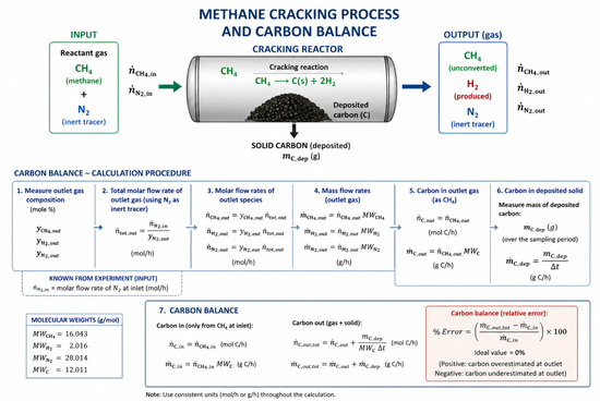
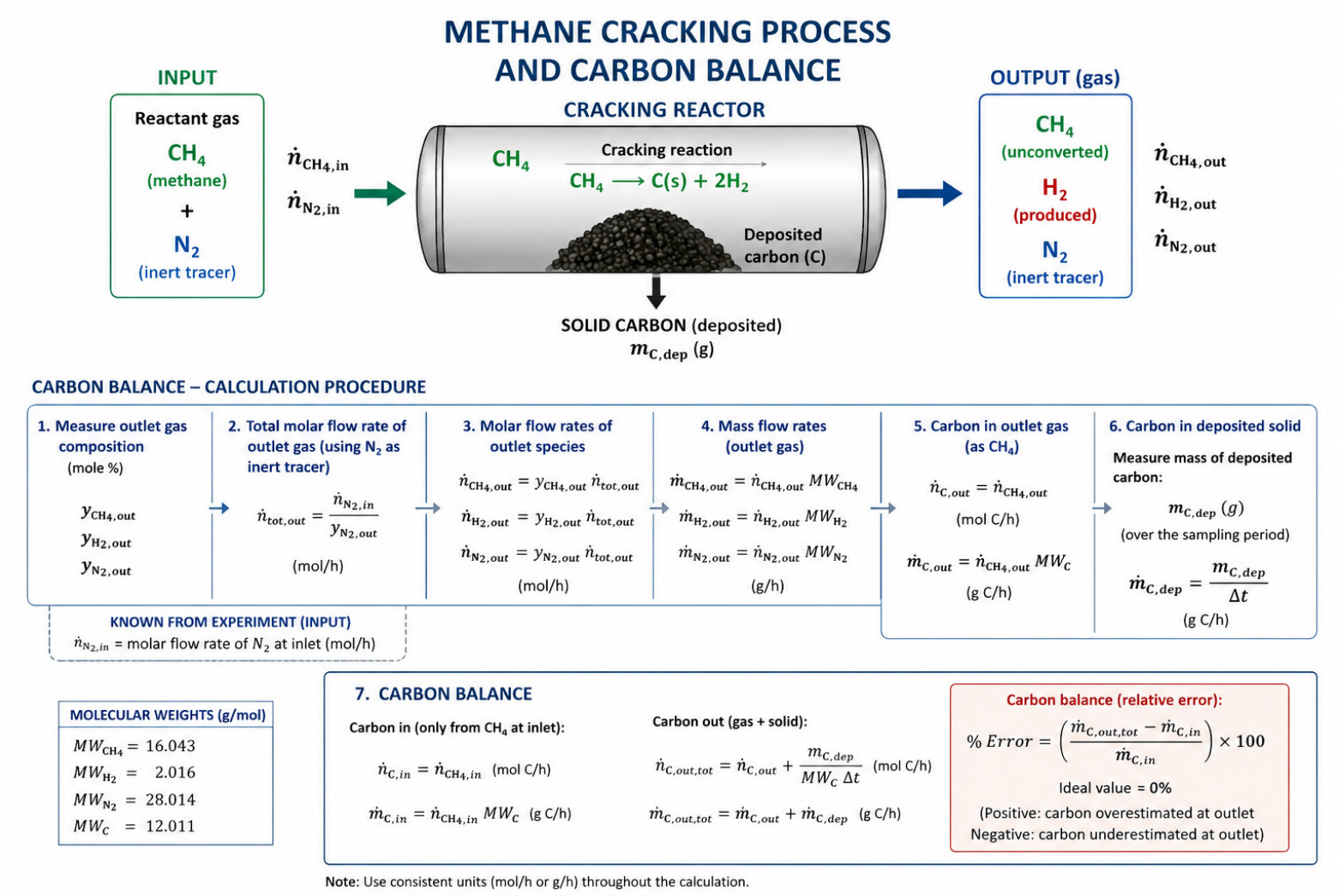
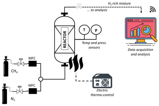
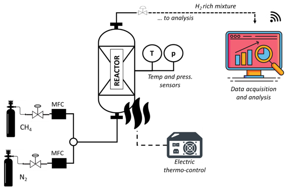
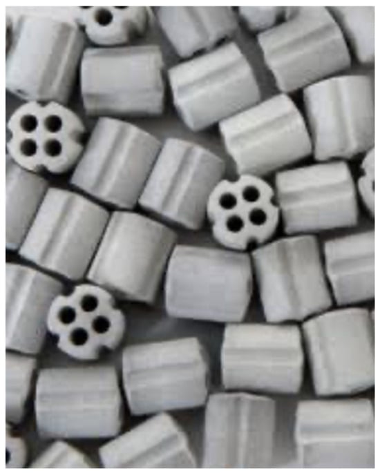
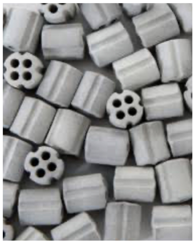
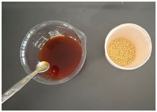
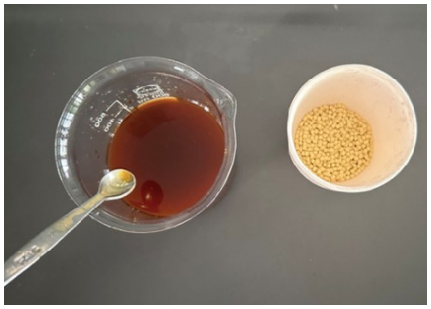
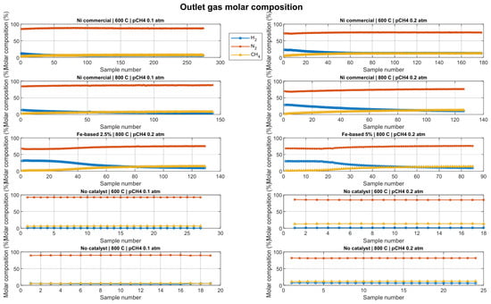
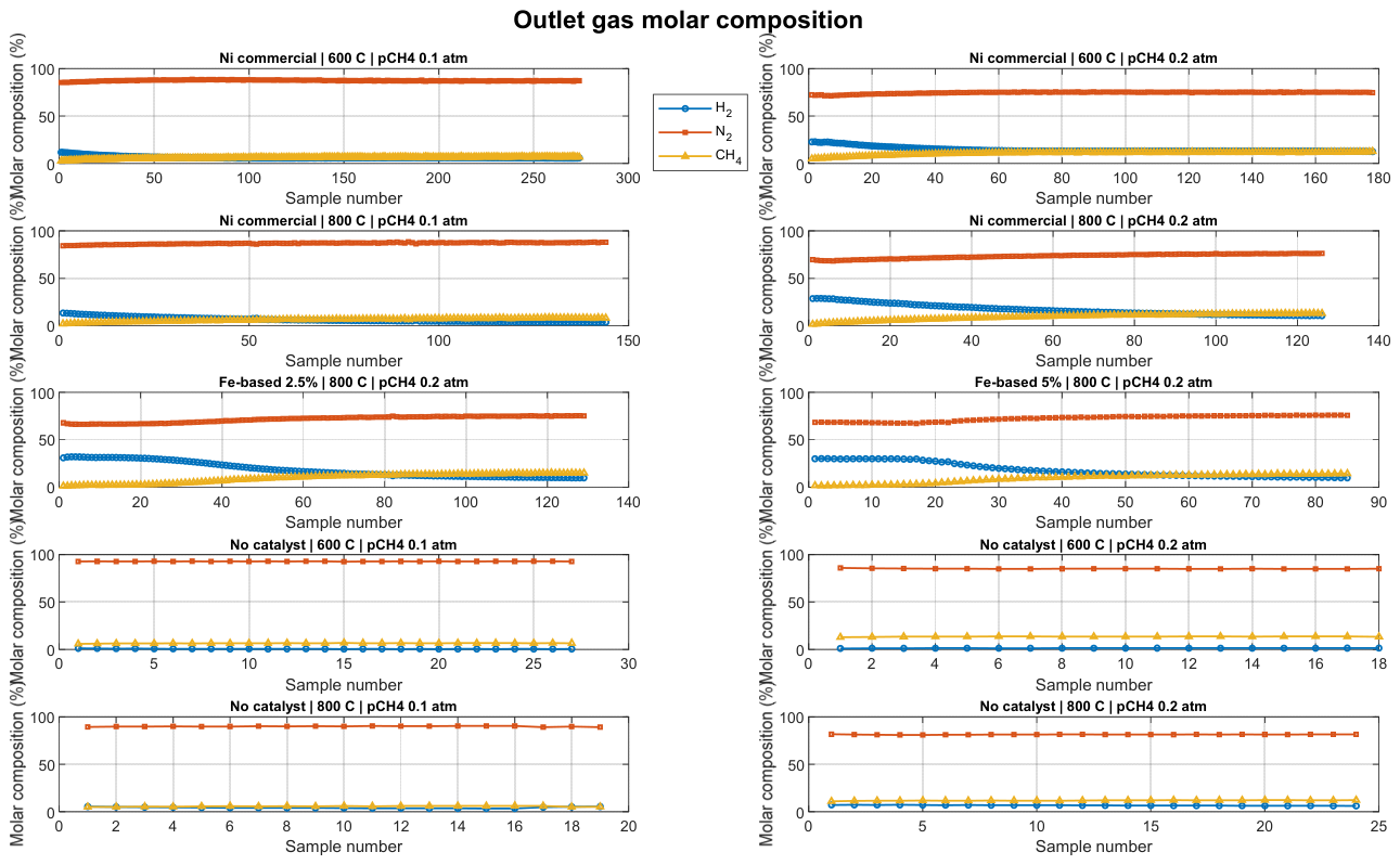
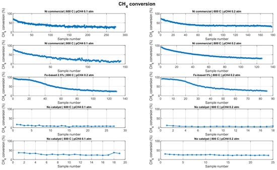
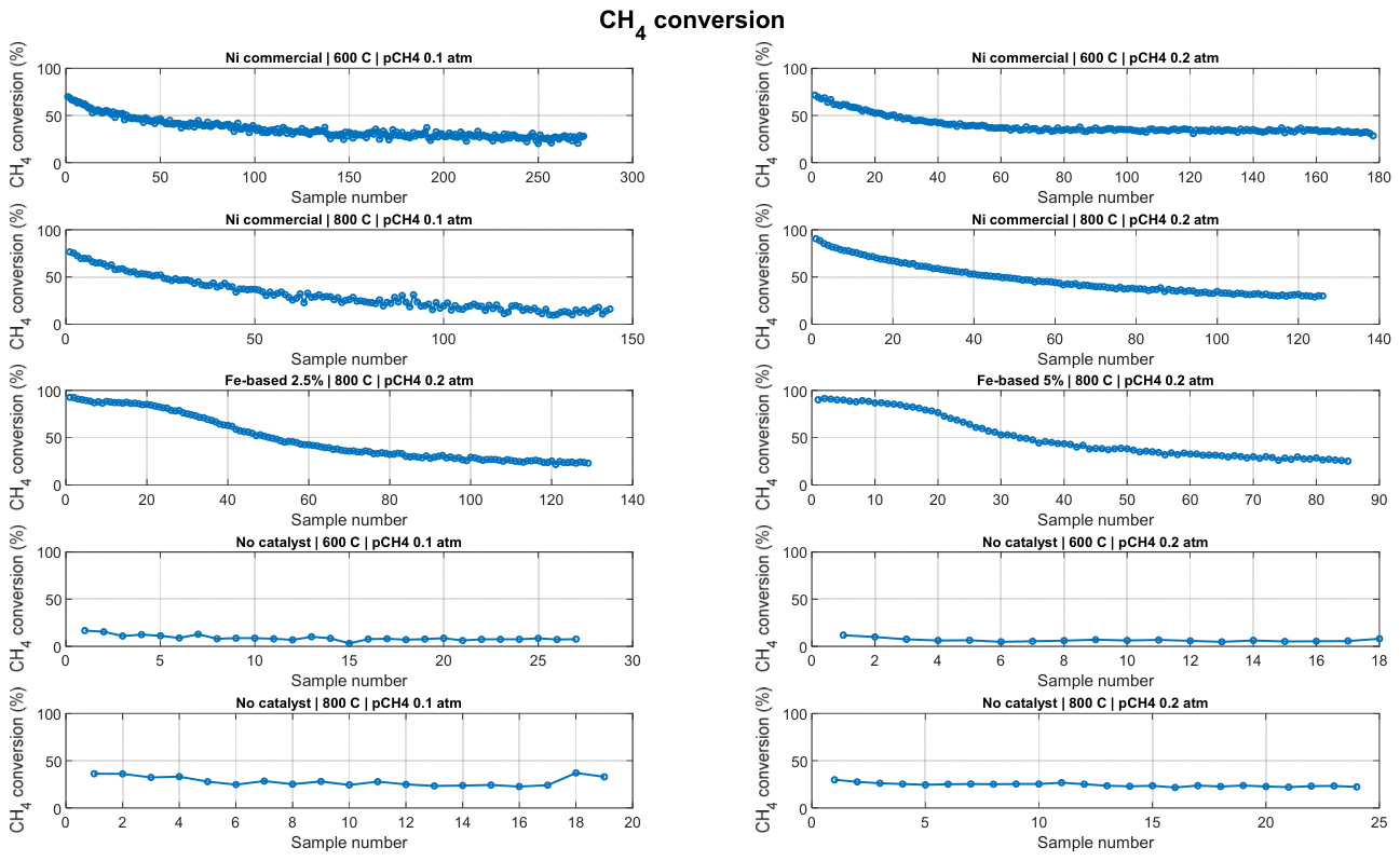
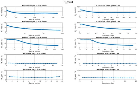
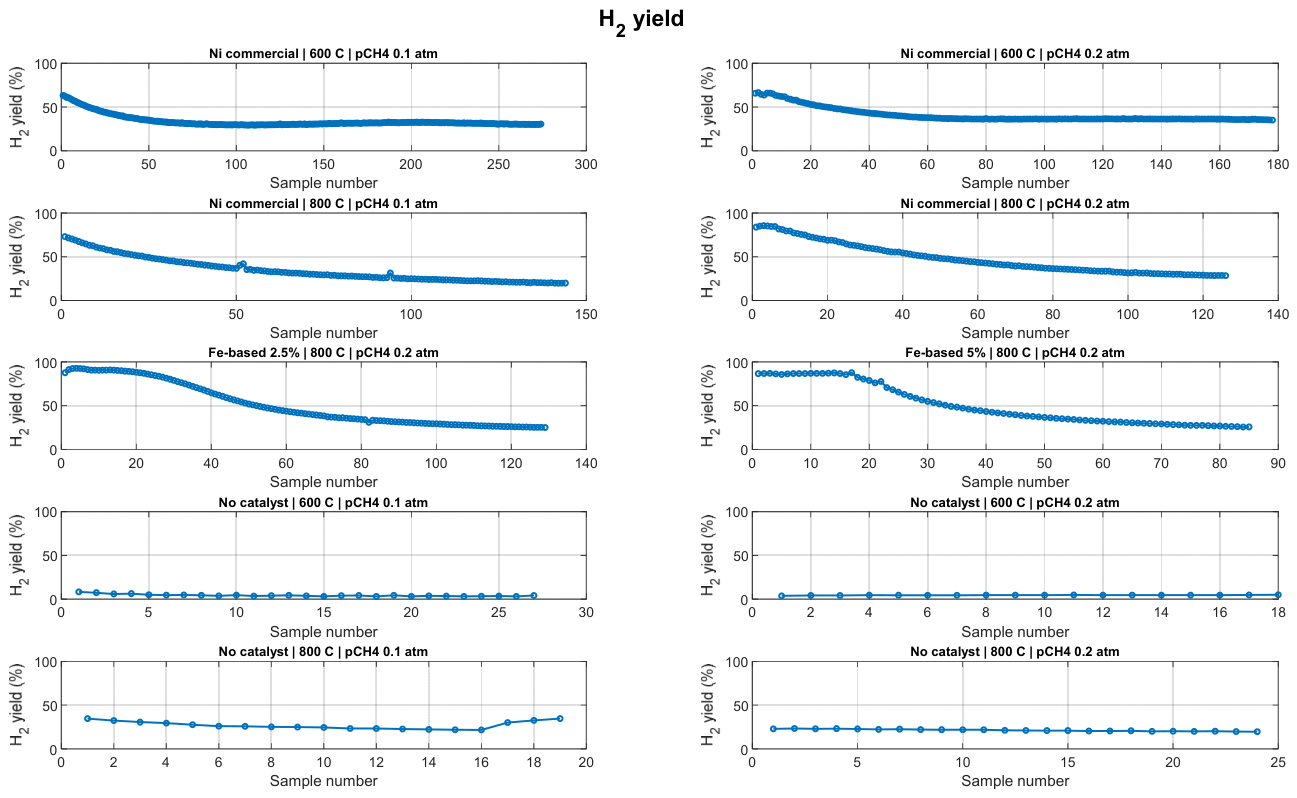
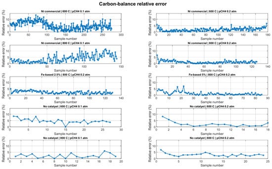
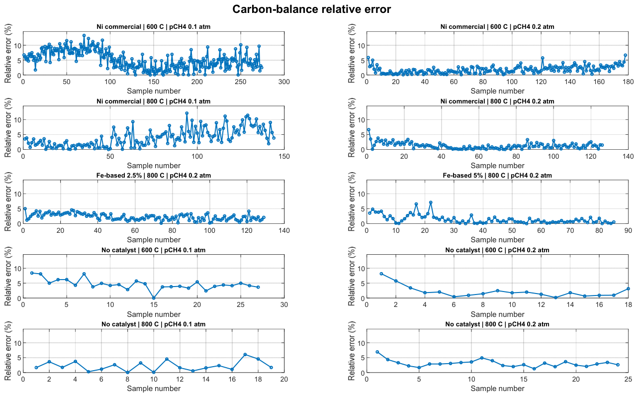
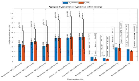
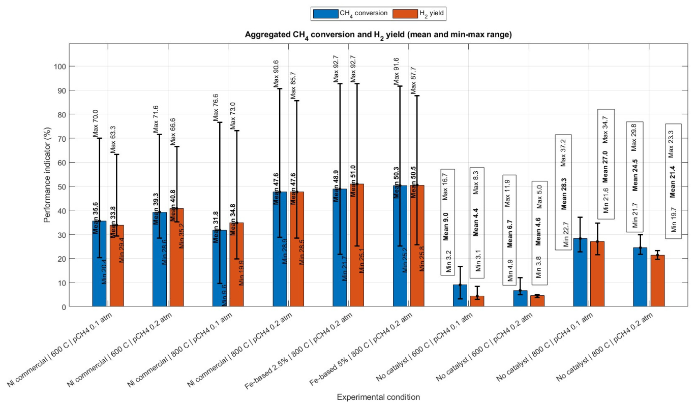
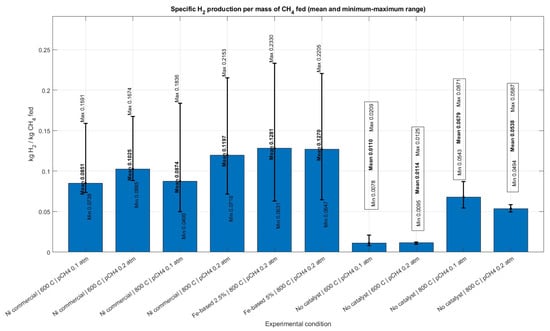
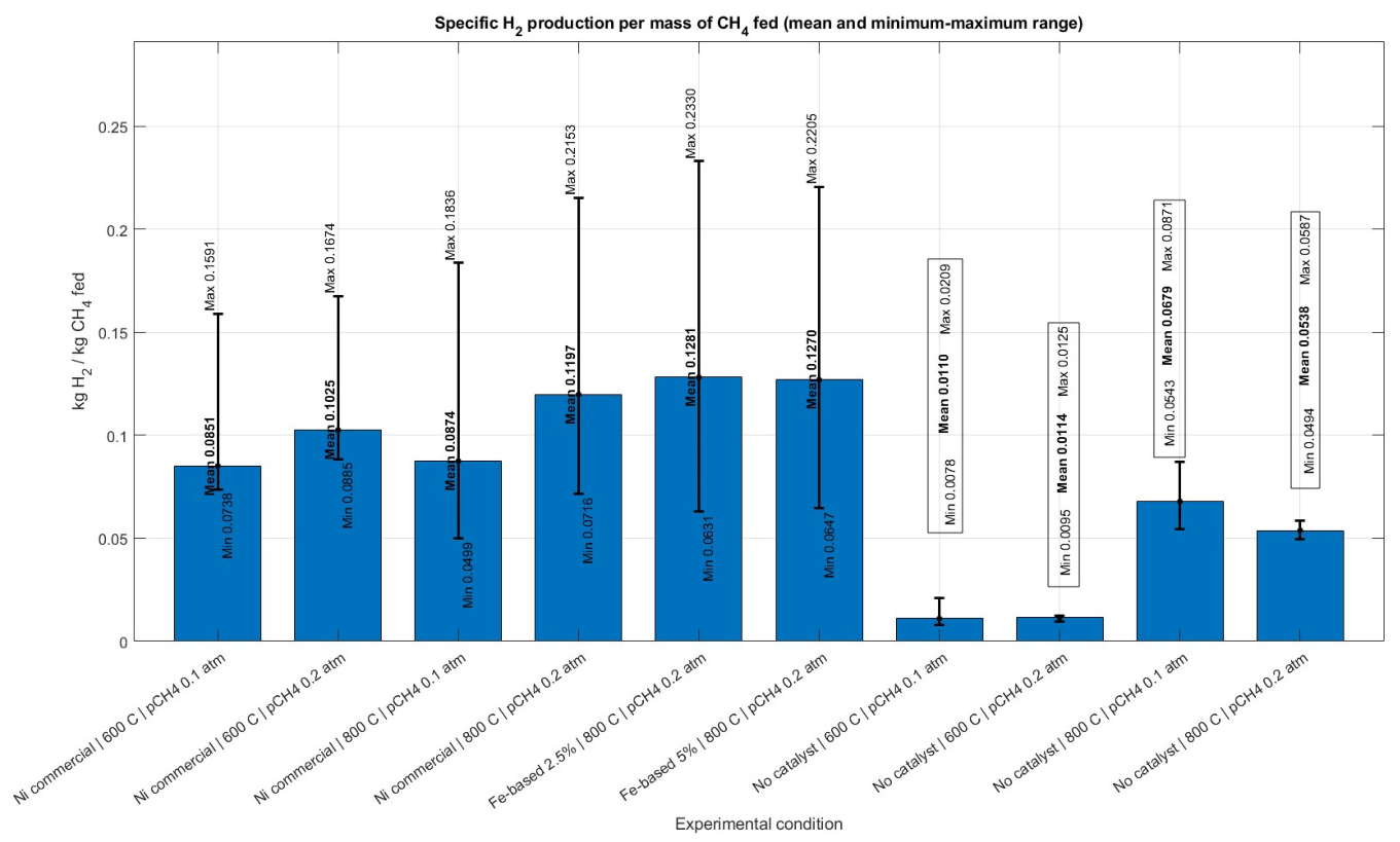
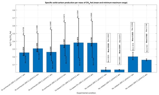
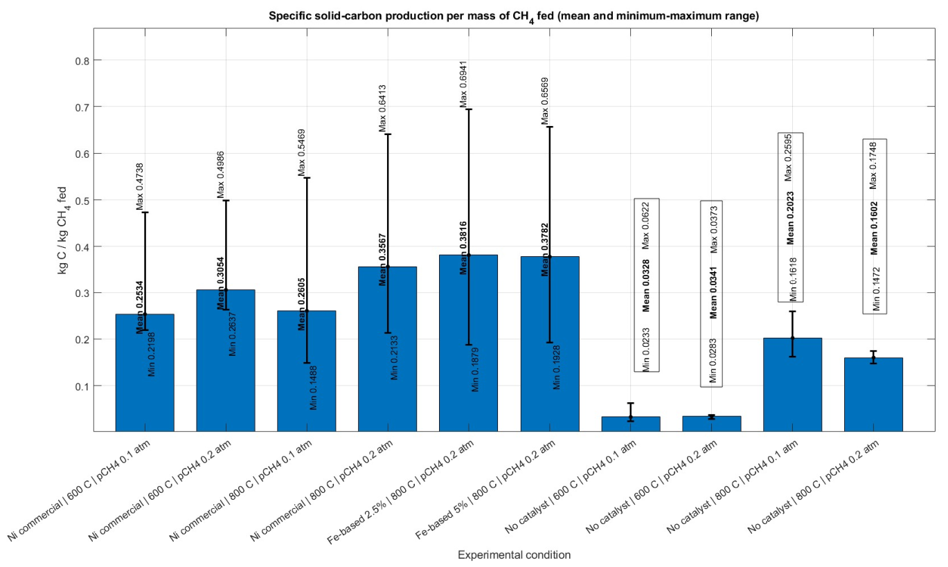

Disclaimer/Publisher’s Note: The statements, opinions and data contained in all publications are solely those of the individual author(s) and contributor(s) and not of MDPI and/or the editor(s). MDPI and/or the editor(s) disclaim responsibility for any injury to people or property resulting from any ideas, methods, instructions or products referred to in the content. |
© 2026 by the authors. Licensee MDPI, Basel, Switzerland. This article is an open access article distributed under the terms and conditions of the Creative Commons Attribution (CC BY) license.