


Abstract
This paper develops certifiable enhancements to a block-backstepping controller for n-DOF underactuated mechanical systems in the Spong normal form. Two offline-computable tests, each reducible to a finite algebraic computation over a prescribed compact domain, are established: a minimum singular-value margin certifying uniform invertibility of the decoupling matrix, and a Jacobian Hurwitz condition certifying local exponential stability of the zero dynamics—the latter derived via an implicit zero-manifold parametrisation. Robustness overlays are introduced, comprising a bi-power term on the velocity-error channel and a matched-disturbance observer. Together, they supply an explicit observer transient budget and a practical entrance bound for . No finite-time convergence of the complete closed-loop state is claimed. The resulting workflow permits offline tuning and verification prior to deployment. A simulation on a high-fidelity cart–pendulum model is consistent with those bounds; it is not a substitute for the offline certificates.
1. Introduction and Problem Formulation
Underactuated mechanical systems arise across a broad range of engineering platforms, including cable-suspended aerial manipulators, variable-stiffness series-elastic robots, ship fin stabilisers, and spacecraft with reaction-wheel attitude control—anywhere the number of independent actuators is fewer than the degrees of freedom to be regulated [1,2,3,4,5]. The breadth of this system class has been systematically catalogued in several survey treatments [6,7,8]. Although partial feedback linearisation emerged as a standard approach in Spong’s framework [2], the inherent actuation deficit impedes system representation in the standard normal form [9,10,11]. Consequently, this precludes the straightforward application of integral backstepping; however, appropriate coordinate transformations can decompose the dynamics into a cascaded structure [12,13], thereby enabling the use of block backstepping [14]. Block backstepping for underactuated systems [15,16] proceeds by constructing a diffeomorphism that decomposes the closed-loop into a cascade and a zero-dynamics subsystem, then stabilising each independently. This structural decomposition provides a constructive, Lyapunov-based framework [17,18] that systematically circumvents the restrictive matching conditions of standard feedback linearisation [19]. An alternative means of avoiding the recursive differentiation intrinsic to standard backstepping is afforded by command-filtered variants [20,21], subsequently extended to adaptive and disturbance-attenuating formulations [22,23,24]; these approaches, however, address analytic tractability rather than the structural actuation deficit that motivates the cascaded block-backstepping decomposition adopted herein. Data-driven alternatives have likewise been investigated for this problem class [25,26], typically at the expense of the a priori stability certificates that the present Lyapunov-based construction is designed to retain.
The nominal block backstepping architecture [15] forms the baseline for an n-DOF underactuated system with actuated degrees of freedom (). Defining the column concatenation operator the configuration is partitioned into unactuated degrees of freedom and actuated degrees of freedom , with . Whilst velocities are denoted , the full state vector is defined as . Following Spong’s partial feedback linearisation ([9], Equation (4)), the plant dynamics are given by
where denotes a bounded disturbance. Define as the compact set of mechanically permissible configurations, and let be a strict velocity bound derived from physical actuation limits. The compact state-space operating domain is defined as
and is chosen so that . To ensure that the nominal control law is well-defined and continuous on , the minimal construction regularity and is imposed [27].
Introducing a constant matrix , the first error coordinate is defined as
with the integral state , which is augmented to eliminate the steady-state offset in . Denoting the time derivative , the virtual control [15] for the unperturbed plant (i.e., henceforth, the unperturbed plant is referred to as the nominal plant) is formulated as
for constants , which yields the second error coordinate . Consequently, the -channel dynamics become
Differentiating along the nominal trajectories yields
Omitting the detailed block-strict feedback derivation ([16], Chapter 3), the resulting nominal control inherently depends on the decoupling matrix and the lumped nonlinearity . Define the matrices , and . The definitions of and are as follows:
In the above description, denotes the Jacobian matrix with respect to a generic vector v. The aforementioned standing regularity hypotheses ensure that and are well-defined and continuous on .
Enforcing the exponentially stable closed-loop cascade
with , yields the backstepping law for the nominal plant (i.e., (2) with ):
where .
Under the structural assumptions established in [15], this law exponentially stabilises the nominal cascade in . However, it lacks a priori certification guaranteeing the uniform invertibility of over a prescribed compact operating set, leaves the internal zero dynamics unverified, and fails to quantify robustness against persistent matched disturbances.
Building upon this framework, this work provides three key contributions that resolve the open issues identified previously:
- A singularity-margin certificate for the invertibility of on , computed offline with an explicit bound [28,29,30].
- An a priori Hurwitz condition on the zero-manifold Jacobian, derived via the implicit function theorem to certify local exponential stability [31,32].
- Composite robustness overlays comprising an Extended State Observer (ESO) [33,34,35,36,37] that yields the ultimate bound and a complete transient budget , and a bi-power term [38] that enforces the practical entrance time for . No finite-time convergence of the complete state is asserted.
2. Offline Certificates
This section separates analytical sufficient conditions from their computational verification. In particular, the nonsingularity of the decoupling matrix and stability of the zero dynamics are properties to be tested, rather than properties imposed in the operating-domain assumptions. A successful verification supplies a certificate for the specified model and domain; an inconclusive computation does not establish either stability or instability.
2.1. Operating Domain and Transformation Time Scale
Assumption 1 (Domain and regularity).
The compact operating domain contains the origin in its interior. The functions f and g are defined on an open neighbourhood of the operating domain, with and . In a neighbourhood of the equilibrium, and . The nominal plant has an equilibrium at the origin, so that . No nonsingularity assumption on ψ is included here.
For the numerical implementation, introduce a time scale and use
The transformation in Section 1 is recovered by setting . All occurrences of , , , and below refer to the same selected value of .
2.2. Verified Decoupling-Matrix Bounds
Let be a finite collection of closed boxes covering . On each box, construct an interval enclosure
where is componentwise nonnegative. The enclosure must include all state dependence and every uncertain parameter included in the claim. For a numerical certificate, elementary functions and matrix operations must be evaluated using verified outward rounding.
Suppose that verified bounds
are available. Define
An ordinary floating-point singular-value calculation without a verified error bound is not sufficient for evaluating .
Proposition 1 (Computable uniform decoupling certificate).
Under Assumption 1, if the verified box enclosures satisfy , then is nonsingular throughout and
Proof.
For , write . Componentwise enclosure gives . The singular-value perturbation inequality yields
Taking the minimum over the covering boxes proves the result. □
For scalar decoupling functions, the calculation simplifies. If and this interval does not contain zero, then
An upper bound needed in the robustness analysis is obtained from the same enclosures:
The offline procedure is as follows:
- 1.
- Specify the operating domain, parameter set and controller transformation;
- 2.
- Construct verified interval enclosures on an initial box partition;
- 3.
- Accept boxes having a strictly positive lower bound;
- 4.
- Bisect unresolved boxes and repeat;
- 5.
- Report either a positive global lower bound or an inconclusive result at the prescribed computational limit.
Dense sampling may be reported as a diagnostic, but is not used in place of the verified covering calculation. No claim is made that an arbitrary nonlinear verification problem necessarily terminates after a prescribed finite number of subdivisions.
2.3. Constructive Zero-Dynamics Test
Set
and define
At the equilibrium, calculate
Assumption 2 (Successful local zero-manifold test).
The equilibrium satisfies . The explicitly constructed matrix is nonsingular, as established either analytically or by a verified positive lower bound
By the implicit function theorem, the constraints locally define , where
Define
and
The zero-dynamics Jacobian is therefore constructed directly as
Thus, no explicit nonlinear solution for is required.
A numerical implementation shall report , its nonsingularity measure, and the eigenvalues of . For a verified floating-point Hurwitz test, one may construct and verify
For a scalar second-order zero-dynamics model, exact coefficient Sign conditions may be used instead.
Lemma 1 (Invariant augmented zero manifold).
Suppose the decoupling and zero-manifold tests succeed. The local invariant augmented zero manifold is
On this manifold, and .
Proof.
On , the identity shows that invariance requires . Conversely, under , the three derivatives , and vanish on . The remaining dynamics are precisely the stated internal dynamics. □
2.4. Explicit Error-Subsystem Stability Test
Lemma 2 (Nominal error dynamics).
For , the nominal augmented error dynamics
with
are exponentially stable.
Proof.
The characteristic polynomial of is
All coefficients are positive. The remaining cubic Routh–Hurwitz inequality is
Its left-hand side minus its right-hand side equals
Hence, is Hurwitz. The Kronecker product repeats its eigenvalues times, establishing the result. □
Theorem 1 (Nominal local exponential stability).
Suppose the decoupling certificate and Assumption 2 hold, and the matrix constructed in (5) is Hurwitz. Then, the nominal augmented equilibrium is locally exponentially stable.
Proof.
The map
has a nonsingular Jacobian at the origin because is nonsingular. In these local coordinates, the nominal closed-loop linearisation is block triangular, with diagonal blocks and . Both blocks are Hurwitz. The nominal vector field is near the equilibrium, so Lyapunov’s indirect method establishes local exponential stability. □
2.5. Explicit Cart–Inverted-Pendulum Specialisation
For the benchmark implementation, let denote the pendulum angle measured from the upright position, and let denote cart displacement. The point-mass cart–pendulum model is
The equilibrium is upright; this convention is used consistently in the controller and simulations.
Let , ,
After nominal partial feedback linearisation,
Here, d has units of acceleration. A physical force disturbance corresponds, for the exact model, to
A derivative bound on therefore does not by itself equal a derivative bound on d.
For scalar , the decoupling function becomes
Suppose
Define
The inequalities and give, for and ,
whenever . This conservative analytical lower bound can be supplemented by a sharper verified interval partition.
At the upright equilibrium, put and
For the ordering ,
The zero-dynamics Jacobian is
For and , the strict sufficient and the necessary coefficient conditions for this matrix to be Hurwitz are
Equivalently,
These explicit conditions make the zero-dynamics test independently reproducible.
The numerical gain search maximises a normalised minimum of the decoupling and zero-dynamics margins over a declared finite candidate set. Its output is described as the best candidate on that set, not as a globally optimal gain.
2.6. Computational Verification of Robust Containment
The nominal stability result is local. It does not establish the robust forward invariance of a prescribed operating domain.
A practical candidate is
where is obtained from a Lyapunov equation for the nominal augmented linearisation. This construction alone does not establish that V is a Lyapunov function for the nonlinear composite controller.
Let
and choose a uniform observer-error budget . With as defined in Assumption 3, define
The last term is the exact support function of the Euclidean observer-error ball.
A successful robust-containment verification consists of the following:
- 1.
- Verified positive definiteness of P;
- 2.
- Verified containment of the projection of in ;
- 3.
- A verified strictly negative upper bound for on ;
- 4.
- Compatibility of with the complete observer transient bound, including the prescribed initial errors;
- 5.
- Verification that the requested physical actuator input remains strictly within its limits throughout the set, or explicit inclusion of the saturation discrepancy in the boundary test.
The boundary calculation can be implemented by interval branch-and-bound: discard boxes not intersecting , accept boxes with a negative upper bound, and subdivide the remaining boxes. State-dependent residual bounds are computed over the whole sublevel set, not only along simulated trajectories.
This procedure verifies an inward-pointing condition for the actual composite vector field. If it succeeds, the sublevel set is a robust invariant set for the stated disturbance and observer-error budgets. If it is inconclusive, the nominal local stability certificate may still hold, but the robust invariance claim must remain unverified. A phase portrait, a decreasing sampled quadratic function, or a Monte Carlo success rate is not a substitute for this test.
3. Composite Robust Control Architecture
The composite controller combines the nominal block-backstepping law with a matched-disturbance observer and a bi-power nonlinear term. The observer estimate and the control input must be expressed in the same partially linearised input coordinates. For the cart–pendulum benchmark, these coordinates have acceleration units, whereas the physical actuator input has force units.
The analytical statements below concern the exact matched model and exact state feedback unless measurement noise, actuator saturation or parameter uncertainty is explicitly included. Simulations with additional uncertainties are reported separately as robustness experiments.
3.1. Extended State Observer and Complete Transient Bound
Let the measured actuated velocity be
The observer is
where is the known input actually applied in the partially linearised coordinates. In the unsaturated case, . When a physical actuator is saturated, the observer must use the corresponding applied input, not the unsaturated request.
Define
where . Suppose d is absolutely continuous and
almost everywhere.
Proposition 2 (Observer transient and ultimate bounds).
For all ,
In particular,
Proof.
The observer-error dynamics are
The disturbance-error initial-condition response is
The impulse response from to is
whose integral over is
The impulse response from n to is
and
The triangle inequality gives (11). The uniform estimate follows from and . Taking the upper limit establishes the ultimate bound. □
The noise-free result in Lemma 4 is recovered by setting . The uniform budget, rather than the ultimate bound alone, must be used in the robust-containment test:
For an unknown initial disturbance, a known upper bound on must be supplied.
For any , an explicit sufficient observer transient time is
with when both initial errors vanish. This guarantees
This follows from and for .
For bandwidth selection, one may minimise the explicitly declared surrogate
When , its unconstrained minimiser is
The selected bandwidth is its projection onto the prescribed admissible interval. This is optimality for the stated surrogate, not a global closed-loop performance claim.
3.2. Bi-Power Nonlinear Term
For , define the componentwise signed power
The nonlinear term is
where
We use the term bi-power because both sublinear and superlinear signed powers are present. No assertion that the complete augmented closed loop is homogeneous or finite-time stable follows merely from this choice.
Under the exact matched model,
is evaluated algebraically. It does not require the numerical differentiation of a noisy angle signal.
3.3. Composite Law and Saturation Discrepancy
The requested virtual input is
Let
denote the discrepancy between the applied and requested virtual inputs. For an unsaturated, exact actuator, .
Lemma 3 (Exact channel decomposition).
Under the exact matched model and exact state feedback,
where
For , write .
Proof.
The transformation gives . Substitute and the definition of . □
Consequently, actuator saturation is not a plotting operation: if it is applied physically, is an additional term in the transformed dynamics. There are two valid certification options:
- 1.
- Verify that saturation is inactive throughout the certified set, including the allowed observer states;
- 2.
- Include a verified bound on in both the invariance and residual calculations.
Using the applied input in the observer avoids attributing known clipping to the unknown disturbance, but does not restore the cancellation lost in the controller.
3.4. Practical Velocity-Error Entrance
Suppose robust containment has been verified and define
Let , and suppose on the certified set. For , a valid residual bound is
Furthermore,
Thus, the aggregate perturbation
satisfies
Proposition 3 (Practical fixed-time entrance of the velocity channel).
Let and
For and ,
The set is forward invariant while the perturbation bound holds. Its entrance time, measured from , is bounded independently of by
for any selected reference speed . For normalised coordinates with , this becomes
Proof.
For ,
The two signed-power estimates follow from the finite-dimensional norm inequalities. For , . The vector field points inward at a positive boundary .
An upper bound on the entrance time is obtained by extending the comparison integral to and splitting it at . On , retain the sublinear term; on , retain the superlinear term. Integrating the two resulting powers yields (19). The zero-residual case follows from the same comparison argument with . □
The total guaranteed time is
This is an entrance guarantee for the transformed velocity error, conditional on robust containment and the stated bounds. It is not a finite-time convergence guarantee for , nor a claim that the physical angle and cart displacement settle within the same time.
The introduction of is essential when only an ultimate observer bound is available: a limsup bound does not imply finite-time entry into the same closed bound without slack.
3.5. Implementation and Validation Protocol
The numerical study distinguishes the following:
- 1.
- Exact-model nominal regulation;
- 2.
- Exact matched-disturbance observer validation;
- 3.
- Deterministic disturbance, measurement-noise and parameter-mismatch experiments;
- 4.
- Multiple-initial-condition entrance experiments;
- 5.
- Seeded Monte Carlo comparisons.
All compared controllers receive the same initial physical state and the same prescribed disturbance and measurement-noise histories. The baseline differs only by the removal of the observer compensation and nonlinear overlay; it is not artificially disadvantaged by a different velocity measurement architecture.
Physical states, requested and applied actuator inputs, saturation duration, observer error, operating-domain exits, and decoupling margins are recorded without artificial amplitude scaling or time-dependent display decay. Failed runs are retained and identified.
The observer bound is compared with simulation only in experiments satisfying its assumptions. Residual maxima computed from finite trajectories are labelled empirical finite-horizon quantities, not verified global bounds. A successful interval verification and a successful simulation are reported as distinct outcomes.
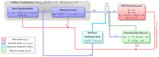
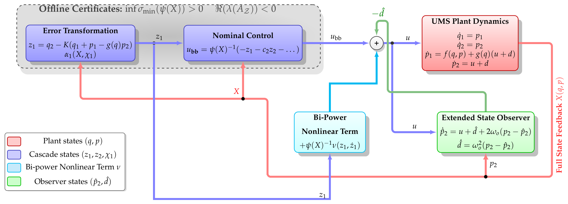
The complete architecture is depicted in Figure 1.
Figure 1.
Composite backstepping architecture.
4. Stability Analysis
Lemma 4 (Observer Estimation Bound).
If , the perturbation estimation error satisfies .
Proof.
Since all block matrices in are scalar multiples of the identity matrix , each component pair obeys identical dynamics; the transfer function from to is
with impulse response .
Since the impulse response is nonnegative (), the integral form of the triangle inequality and the absolute homogeneity of the Euclidean norm permit the scalar weight to pass through the norm. Accounting for the unforced initial-condition response, the complete error norm satisfies
Since is Hurwitz [36], the transient term exponentially vanishes as . Bounding the remaining convolution integral yields the ultimate limit: □
Lemma 5 (Finite-time entrance).
Let satisfy
where , , and .
- Set Then, for almost every t such that , Consequently, if , then for all , where
Proof.
For , the map is differentiable almost everywhere, yielding the time derivative . By the element-wise definition of the operator, . Since , the standard inclusion property of finite-dimensional norms implies . Consequently,
The Cauchy–Schwarz inequality and the uniform bound on yield . Substituting the dynamics of into the expression for and discarding the nonnegative term establishes the differential inequality
Integrating this inequality via the comparison principle [18] yields the stated entrance time . □
Assumption 3 (Robust compact containment).
Let , and be a Lyapunov function for the nominal closed-loop system. There exists a constant such that the compact sublevel set ([17], Chapter 4)
is strictly contained within the domain of attraction of the nominal equilibrium. Furthermore, there exists a uniform bound such that, for all and all observer errors satisfying , the following strict dissipation inequality holds:
where is the nominal closed-loop vector field, and the input distribution matrix is defined as the block column vector
Theorem 2 (Conditional robust containment and practical entrance).
Suppose the decoupling and local zero-dynamics tests succeed. Let a compact sublevel set have its physical-state projection contained in , and suppose the robust boundary test in Section 2.6 has been verified for an observer-error budget .
Assume that the disturbance and initial observer errors satisfy
where is given by (12). Assume also that actuator saturation is either excluded on the certified set or included explicitly in the verified boundary and residual bounds. For noisy state feedback outside the ESO, the associated controller perturbations must additionally be included in those bounds.
Then, every solution starting in remains in and admits continuation for all . For every , the transformed velocity error enters the set specified in Proposition 3 no later than . No finite-time convergence of the complete state to the origin is asserted.
Proof.
Proposition 2 supplies the required observer-error bound for the entire transient, not only asymptotically. The verified boundary inequality therefore makes the vector field strictly inward pointing on . This establishes forward invariance. The bounded disturbance, bounded physical and integral states, and bounded observer errors preclude a finite escape of the augmented solution. The residual bounds and the entrance claim follow from Proposition 3. □
Remark 1 (Explicit residual bound).
Let , , , and let be the bound from Lemma 4. Then,
5. Simulation Results
The numerical study follows the protocol in Section 3. Offline algebraic tests on the declared box are reported first; closed-loop records are reported afterwards. A successful analytical or interval certificate and a successful simulation are distinct outcomes. Three implementations share the same plant, the same , the same and the same coefficients: the nominal law in (2) (BB), that law with (10) (BB+ESO), and the composite law in (16) (BB+ESO+FT).
5.1. Plant, Box and Implemented Coefficients
The plant is a virtual replica of the Digital Pendulum System (Feedback Instruments, model 33-005-PCI) ([16], Section 4.6). Parameters and the design box
are listed in Table 1. Here, and . As in Section 2.5, the matched signal d lives in the partially linearised acceleration channel. A physical force satisfies on the exact model, so a bound on is not, by itself, a bound on .
Table 1.
Cart–pendulum parameters and design box . Inertias follow . Friction and the force/rail limits are modelling assumptions of the virtual replica.
Implemented gains appear in Table 2. In particular, and . The cascade pair satisfies , whence and . The bi-power term is evaluated on the normalised arguments and rather than on directly. Because is homogeneous of degree , this is a rescaling of (15): the tabulated and the comparison time belong to those normalised coordinates, which are also the coordinates in which Proposition 3 is applied.
Table 2.
Implemented controller and offline numbers at the selected k. The pair is the split of used in the code. The weights and are those of the normalised bi-power term.
Integrations use RK4 with on a horizon of . A step-halving check on the same vector field, controller and noise functions produced a four-state discrepancy no larger than in SI units.
The actuator is limited to . Lemma 3 holds with only when . In the numerical plant, the requested force is clipped, and the observer is fed rather than . Across the records below, the observed saturation fraction is either zero or of order of the horizon. That sampled fact does not replace the set-wise test in Section 2.6.
5.2. Offline Tests of and
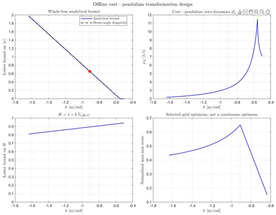
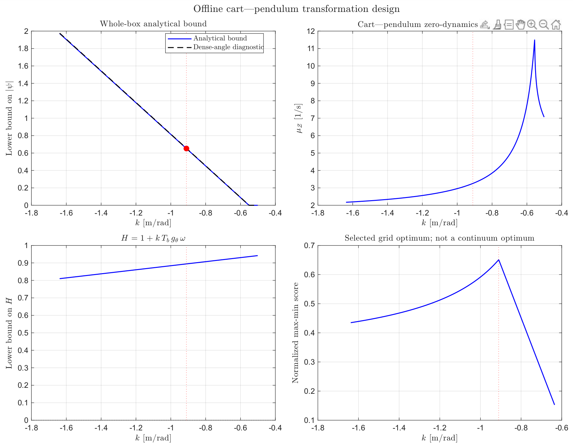
For this plant, is the scalar from Section 2.5. Figure 2 plots the whole-box analytical lower bound against k, together with a dense-angle diagnostic. The two curves agree on the plotted interval. The diagnostic is not a substitute for the verified covering argument in Proposition 1; it is reported as a check on the conservative closed-form bound. Because is scalar, the calculation is cheap. For larger n, the same test must be replaced by the box-covering procedure from Section 2.
Figure 2.
Offline transformation design on .
The marker is the maximiser of a normalised max–min score on a declared finite grid, not a continuum optimiser. At that value, the design script returns
Thus, is nonsingular and the implemented is Hurwitz with spectral abscissa . The two eigenvalues are the roots of that same implemented matrix, assembled by (5) in the coordinates of the numerical model. They are not inferred from the point-mass specialisation in Section 2.5 unless that specialisation is the model used in code: the virtual replica uses , whereas the displayed point-mass Jacobian uses .
The top-left panel in Figure 2 is a lower bound on . It does not give , which is a separate upper estimate at the selected k. On the recorded orbits of the next subsections, remains near . Residual quantities and in the sense of the explicit residual bound and of Proposition 3 further require extrema of on a declared . Those extrema are not read from a single trajectory, and they are not claimed here as verified set-wise bounds.
5.3. Observer Envelope and Decoupling Along One Record
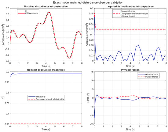
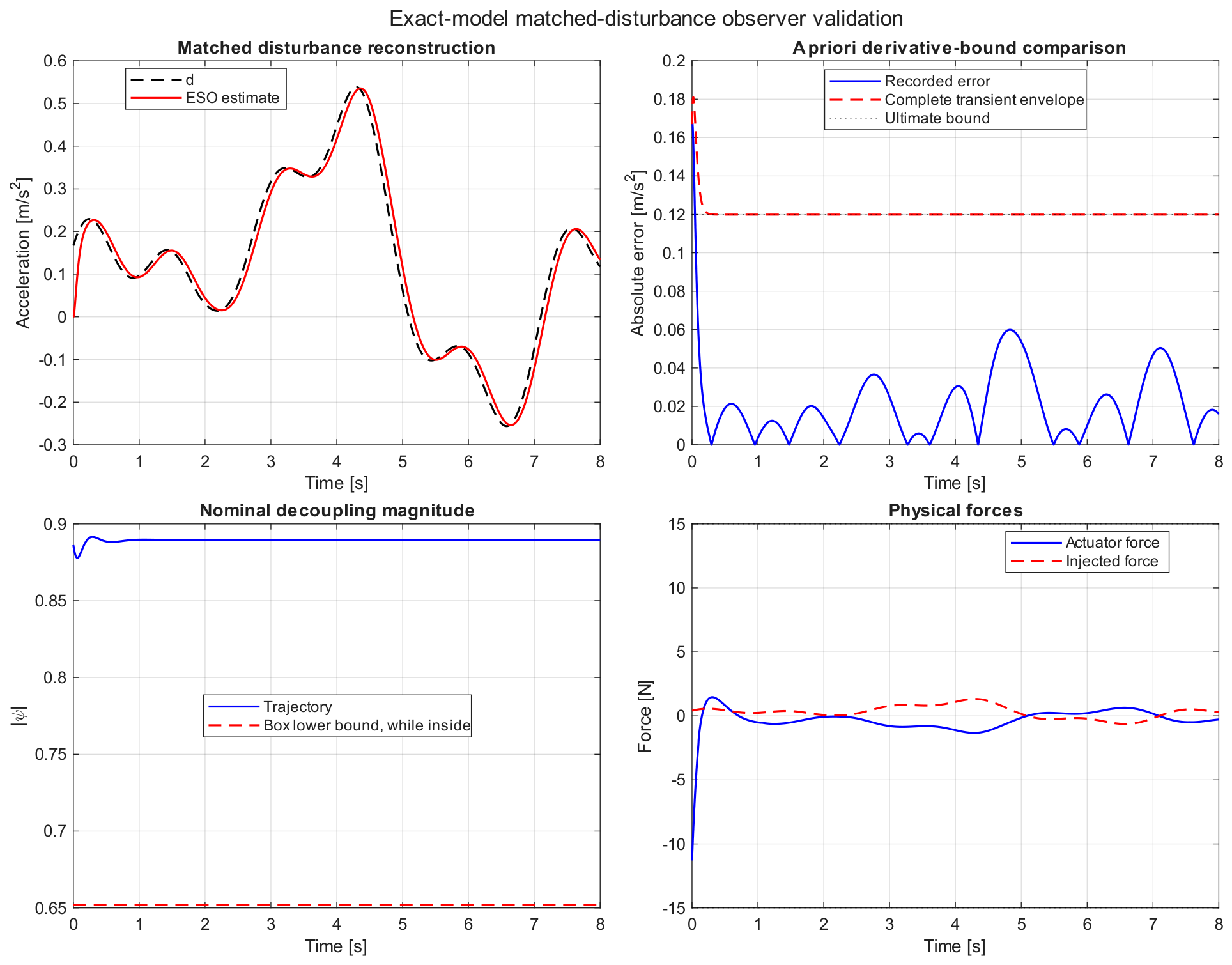
Lemma 4 is an ultimate bound. Theorem 2 uses the complete transient budget of Proposition 2. Figure 3 shows both, for the injected acceleration-channel signal of this campaign (not the force-rate figure of an earlier draft). The ultimate line in the figure is at the implemented and at the rate bound of that same injected d. After about , the recorded lies below that line; the first samples do not. Forward invariance of a candidate on this record is therefore an observed property of the initialisation, not a corollary of the limsup alone.
Figure 3.
Exact–model observer record.
Along the same orbit, remains near , above , whilst the state stays inside . Requested and injected forces are plotted together so that any approach to can be seen. On this record the applied force stays inside the limiter after the opening sample.
5.4. One Common Stress Comparison
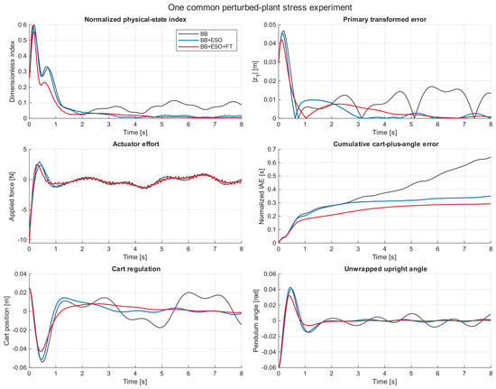
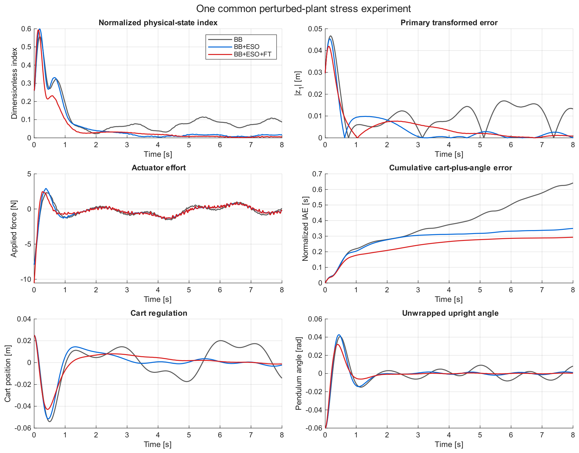
A single Lipschitz disturbance and a common initial condition are applied to all three laws (Figure 4, Table 3). BB leaves a persistent oscillation. BB+ESO removes most of that residual. BB+ESO+FT further reduces after the first second and records the smallest terminal index and the smallest IAE on this horizon. Settling times are (BB+ESO) and (BB+ESO+FT); BB does not meet the settling test in . The minimum observed is .
Figure 4.
Common perturbed–plant experiment.
Table 3.
Quantitative comparison. Stress: one common disturbance and initial condition (seed 73). Monte Carlo: median (minimum, maximum) over 24 shared seeds. BB settling statistics use the 21 records that settle. IAEx in metre-seconds; IAEθ in radian-seconds.
Two caveats belong here. First, the record is not a proof of Theorem 2, and the figure does not display . The comparison time associated with Proposition 3, after a residual radius has been sampled a posteriori in the normalised coordinates of Table 2, is . The last entry of into the engineering band on the recorded family occurs earlier than that mark. Second, total variation of the applied force is larger for BB+ESO+FT than for BB+ESO ( against on this record). The bi-power term buys IAE and terminal error at the price of a more lively actuator.
5.5. Seeded Monte Carlo
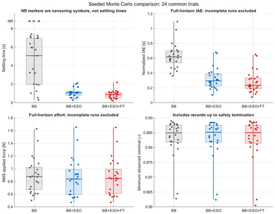
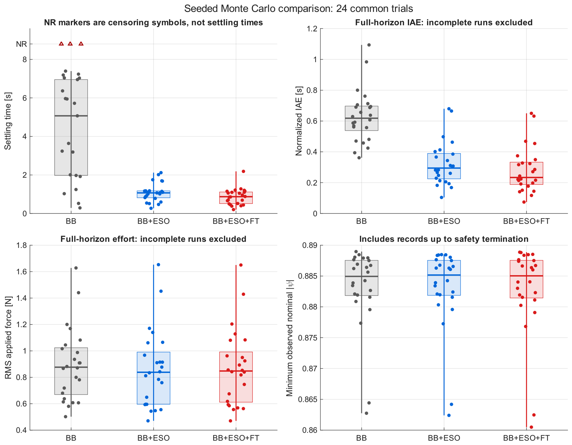
Twenty-four common seeds are reused for the three controllers (Figure 5, Table 3). Every run completed . Under a strict success test combining settling, terminal index and box containment, BB succeeds on seeds (3 censored non-settling records, not crashes); BB+ESO and BB+ESO+FT succeed on . Median settling times fall from (BB, on those records that settle) to and . Median normalised IAE falls from to and . Median RMS force is essentially unchanged (≈0.84–0.88 ); total variation is systematically higher once the bi-power term is active.
Figure 5.
Seeded Monte Carlo on 24 common trials. Settling-time NR markers are censored BB records, not numerical settling times. IAE and RMS force use completed horizons only (all runs completed). Minimum observed includes records up to any safety stop. The overlays improve settling and IAE; they do not reduce RMS effort.
The smallest among all 72 records is , still above . The largest peak domain ratio is , so no sampled orbit leaves . These are counts from a finite seeded study. They are not hypothesis tests, not empirical probabilities of stability, and not a covering of . In the language of Section 2.6, they do not replace the interval boundary test in Assumption 3.
No finite-time convergence of to the origin is inferred from any of the four figures. Additional diagnostics generated on the same campaign (nominal regulation, phase portraits, a sampled quadratic that is not a containment certificate, a velocity-entrance family, completion counts, a four-term anatomy of , and the step-refinement overlay) are omitted from the main text.
6. Conclusions
The offline tests decide the invertibility of on and local exponential stability of the zero dynamics. Both are properties of a declared model and a declared compact set: a completed covering with gives and a usable inverse bound. A Hurwitz Jacobian is a local statement about the unforced zero dynamics. It is not a robustness certificate for the perturbed loop.
The overlays address that gap only in the sense made precise by Theorem 2. The observer contributes the ultimate bound and the transient budget used in the invariance argument. The bi-power term contributes the entrance time for . Neither overlay is claimed to render the full state finite-time stable. The cart–pendulum records in Section 5 are consistent with those distinctions; they are not a covering of Assumption 3. The construction remains the block-backstepping law of [15], with the tests and overlays attached.
Author Contributions
Methodology, formal analysis, investigation and draft preparation, S.R.; supervision, review and editing, M.R. All authors have read and agreed to the published version of the manuscript.
Funding
This research received no external funding.
Institutional Review Board Statement
Not applicable.
Informed Consent Statement
Not applicable.
Data Availability Statement
The original contributions presented in this study are included in the article. Further inquiries can be directed to the corresponding author.
Conflicts of Interest
The authors declare no conflicts of interest.
Abbreviations
The following abbreviations are used in this manuscript:
| ESO | Extended State Observer |
| FT | Finite-Time |
| DOF | Degrees of Freedom |
References
- Lu, B.; Fang, Y. Online trajectory planning control for a class of underactuated mechanical systems. IEEE Trans. Autom. Control 2024, 69, 442–448. [Google Scholar] [CrossRef] [Scilit]
- Reyhanoglu, M.; van der Schaft, A.; McClamroch, N.H.; Kolmanovsky, I. Dynamics and Control of a Class of Underactuated Mechanical Systems. IEEE Trans. Autom. Control 1999, 44, 1663–1671. [Google Scholar] [CrossRef] [Scilit]
- Wang, B.; Nersesov, S.; Ashrafiuon, H. Quasi-LPV Control Design for a Class of Underactuated Mechanical Systems. In Proceedings of the 2022 American Control Conference (ACC), Atlanta, GA, USA, 8–10 June 2022; pp. 1904–1909. [Google Scholar] [CrossRef] [Scilit]
- Franco, E.; Arpenti, P.; Donaire, A.; Ruggiero, F. Integral IDA-PBC for Underactuated Mechanical Systems Subject to Matched and Unmatched Disturbances. IEEE Control Syst. Lett. 2024, 8, 568–573. [Google Scholar] [CrossRef] [Scilit]
- Emirsajłow, Z.; Barciński, T. A Robust Asymptotic Tracking Controller for an Uncertain 2DOF Underactuated Mechanical System Motivated by a Satellite Attitude Control Problem. Int. J. Appl. Math. Comput. Sci. 2025, 35, 97–116. [Google Scholar] [CrossRef] [Scilit]
- Krafes, S.; Chalh, Z.; Saka, A. A Review on the Control of Second Order Underactuated Mechanical Systems. Complexity 2018, 2018, 9573514, Correction in Complexity 2020, 2020, 1629749. https://doi.org/10.1155/2020/1629749. [Google Scholar] [CrossRef] [Scilit]
- Liu, Y.; Yu, H. A Survey of Underactuated Mechanical Systems. IET Control Theory Appl. 2013, 7, 921–935. [Google Scholar] [CrossRef] [Scilit]
- Huang, Z.; Yu, C.; Zeng, B.; Gong, X.; Zhou, H. A Survey of Planar Underactuated Mechanical System. Machines 2024, 12, 829. [Google Scholar] [CrossRef] [Scilit]
- Olfati-Saber, R. Normal forms for underactuated mechanical systems with symmetry. IEEE Trans. Autom. Control 2002, 47, 305–308. [Google Scholar] [CrossRef] [Scilit]
- Fantoni, I.; Lozano, R. Non-Linear Control for Underactuated Mechanical Systems; Springer: London, UK, 2001. [Google Scholar] [CrossRef] [Scilit]
- Xin, X.; Liu, Y. Control Design and Analysis for Underactuated Robotic Systems; Springer: London, UK, 2014. [Google Scholar] [CrossRef] [Scilit]
- Olfati-Saber, R. Cascade Normal Forms for Underactuated Mechanical Systems. In Proceedings of the 39th IEEE Conference on Decision and Control, Sydney, Australia, 12–15 December 2000; pp. 2162–2167. [Google Scholar] [CrossRef] [Scilit]
- Olfati-Saber, R. Nonlinear Control and Reduction of Underactuated Systems with Symmetry. II. Unactuated Shape Variables Case. In Proceedings of the Proceedings of the 40th IEEE Conference on Decision and Control, Orlando, FL, USA, 4–7 December 2001; pp. 4164–4169. [Google Scholar] [CrossRef] [Scilit]
- Li, N.; Liu, X.; Liu, C.; Wang, H.; Ju, J.; Li, C. A novel block backstepping-based trajectory tracking control with zero dynamics stability for underactuated overhead cranes. ISA Trans. 2025, 166, 379–392. [Google Scholar] [CrossRef] [Scilit]
- Rudra, S.; Barai, R.K.; Maitra, M. Nonlinear State Feedback Controller Design for Underactuated Mechanical System: A Modified Block Backstepping Approach. ISA Trans. 2014, 53, 317–326. [Google Scholar] [CrossRef] [Scilit]
- Rudra, S.; Barai, R.K.; Maitra, M. Block Backstepping Design of Nonlinear State Feedback Control Law for Underactuated Mechanical Systems; Springer: Singapore, 2017. [Google Scholar] [CrossRef] [Scilit]
- Khalil, H. Nonlinear Systems; Pearson Education, Prentice Hall: Upper Saddle River, NJ, USA, 2002. [Google Scholar]
- Hahn, W. Stability of Motion; Grundlehren der Mathematischen Wissenschaften; Springer: Berlin/Heidelberg, Germany, 2012. [Google Scholar] [CrossRef] [Scilit]
- Krstic, M.; Kokotovic, P.V.; Kanellakopoulos, I. Nonlinear and Adaptive Control Design, 1st ed.; John Wiley & Sons, Inc.: Hoboken, NJ, USA, 1995. [Google Scholar]
- Farrell, J.A.; Polycarpou, M.; Sharma, M.; Dong, W. Command Filtered Backstepping. IEEE Trans. Autom. Control 2009, 54, 1391–1395. [Google Scholar] [CrossRef] [Scilit]
- Ye, H.; Song, Y. Backstepping Design Embedded With Time-Varying Command Filters. IEEE Trans. Circuits Syst. II Express Briefs 2022, 69, 2832–2836. [Google Scholar] [CrossRef] [Scilit]
- Zhu, J.; Li, S.; Liu, Z. Adaptive command filter control for switched time-delay systems with dead-zone based on an exact disturbance observer. Int. J. Robust Nonlinear Control 2024, 34, 10131–10159. [Google Scholar] [CrossRef] [Scilit]
- Xu, D.; Dai, Y.; Yang, C.; Yan, X. Adaptive fuzzy sliding mode command-filtered backstepping control for islanded PV microgrid with energy storage system. J. Frankl. Inst. 2019, 356, 7025–7046. [Google Scholar] [CrossRef] [Scilit]
- Mercorelli, P. Feedforward and repetitive control of a servo piezo-mechanical hydraulic actuator. J. Phys. Conf. Ser. 2020, 1564, 012005. [Google Scholar] [CrossRef] [Scilit]
- Turrisi, G.; Capotondi, M.; Gaz, C.; Modugno, V.; Oriolo, G.; De Luca, A. On-Line Learning for Planning and Control of Underactuated Robots with Uncertain Dynamics. IEEE Robot. Autom. Lett. 2022, 7, 358–365. [Google Scholar] [CrossRef] [Scilit]
- Turcato, N.; Calì, M.; Dalla Libera, A.; Giacomuzzo, G.; Carli, R.; Romeres, D. Learning Global Control of Underactuated Systems with Model-Based Reinforcement Learning. arXiv 2025, arXiv:2504.06721. [Google Scholar] [CrossRef] [Scilit]
- Royden, H.; Fitzpatrick, P. Real Analysis; Pearson Modern Classics for Advanced Mathematics Series; Pearson: London, UK, 2018. [Google Scholar]
- Horn, R.A.; Johnson, C.R. Matrix Analysis, 2nd ed.; Cambridge University Press: Cambridge, UK, 2012. [Google Scholar] [CrossRef] [Scilit]
- Moore, R.E.; Kearfott, R.B.; Cloud, M.J. Introduction to Interval Analysis; Society for Industrial and Applied Mathematics: Philadelphia, PA, USA, 2009. [Google Scholar] [CrossRef] [Scilit]
- Boyd, S.; Vandenberghe, L. Convex Optimization; Cambridge University Press: Cambridge, UK, 2004. [Google Scholar] [CrossRef] [Scilit]
- Krantz, S.G.; Parks, H.R. The Implicit Function Theorem: History, Theory, and Applications; Birkhäuser: Boston, MA, USA, 2002. [Google Scholar] [CrossRef] [Scilit]
- Teschl, G. Ordinary Differential Equations and Dynamical Systems; American Mathematical Society: Providence, RI, USA, 2012; Volume 140. [Google Scholar]
- Le, D.T.; Dao, Q.T. A model-assisted ESO-based nonlinear ADRC for robust transportation control of a biglide parallel robot. Results Control Optim. 2026, 24, 100761. [Google Scholar] [CrossRef] [Scilit]
- Zhu, W.; Du, H. Global Uniform Finite-Time Output Feedback Stabilization for Disturbed Nonlinear Uncertain Systems: Backstepping-like Observer and Nonseparation Principle Design. SIAM J. Control Optim. 2024, 62, 1717–1736. [Google Scholar] [CrossRef] [Scilit]
- Dao, K.L.; Tran, M.K.; Tong, T.L.; Duong, M.D. Disturbance observer integrated proportional–derivative sliding mode control for trajectory tracking control of quadrotor UAVs. Results Control Optim. 2026, 24, 100769. [Google Scholar] [CrossRef] [Scilit]
- Guo, B.Z.; Zhao, Z.L. On the convergence of an extended state observer for nonlinear systems with uncertainty. Syst. Control Lett. 2011, 60, 420–430. [Google Scholar] [CrossRef] [Scilit]
- Darouach, M. Complements to full order observer design for linear systems with unknown inputs. Appl. Math. Lett. 2009, 22, 1107–1111. [Google Scholar] [CrossRef] [Scilit]
- Polyakov, A.; Krstic, M. Finite- and Fixed-Time Nonovershooting Stabilizers and Safety Filters by Homogeneous Feedback. IEEE Trans. Autom. Control 2023, 68, 6434–6449. [Google Scholar] [CrossRef] [Scilit]

Disclaimer/Publisher’s Note: The statements, opinions and data contained in all publications are solely those of the individual author(s) and contributor(s) and not of MDPI and/or the editor(s). MDPI and/or the editor(s) disclaim responsibility for any injury to people or property resulting from any ideas, methods, instructions or products referred to in the content. |
© 2026 by the authors. Licensee MDPI, Basel, Switzerland. This article is an open access article distributed under the terms and conditions of the Creative Commons Attribution (CC BY) license.