


Abstract
In response to the need for cost-effective and resilient drivetrain architectures in renewable energy emulation platforms, this paper proposes a wind turbine emulator (WTE) designed to enhance the operational efficiency of variable-speed wind turbines (WTs) connected to electric generators in power grid applications. The proposed emulator relies on a robust sensorless vector-controlled induction motor (IM) drive fed by a reduced-switch soft–voltage source inverter (Soft-VSI) topology. The proposed control chain combines a second-order super-twisting sliding-mode flux observer, based on stator measurements, with a modified MRAS speed estimator whose Popov hyperstability offers explicit PI tuning and ensures stable sensorless speed convergence. The complete WTE design, from the aerodynamic model to the Soft-VSI induction motor drive, is implemented and evaluated in MATLAB/Simulink environment. A Mexican hat wind speed profile is used to excite the emulator and assess its dynamic behavior under diverse transient conditions. The simulation results demonstrate fast convergence of the estimated flux and speed, stable closed-loop operation when using the estimated speed, and strong robustness against no-loaded and loaded operations and rotor-resistance variations. Moreover, a comparative analysis between the proposed control scheme and a conventional first-order sliding-mode flux observer is carried out to highlight the enhanced flux and speed estimation accuracy, reduced chattering, and improved dynamic robustness of the WTE. The proposed framework provides a flexible tool to support the energy transition through the development of advanced wind energy system control strategies.
1. Introduction
Renewable energy plays a central role in the global energy transition, and wind power has emerged as one of the most promising options for large-scale electricity generation [1,2]. Its appeal lies not only in its near-zero direct greenhouse gas emissions, but also in the broad geographical availability of wind resources, which has supported the rapid deployment of wind energy conversion systems (WECSs) over the past few decades [3]. This expansion is driven by the strategic objective of building a sustainable, low-carbon energy mix that reduces dependence on fossil fuels, mitigates climate change, and supports long-term environmental commitments [4]. Moreover, recent volatility in natural gas prices has highlighted the economic vulnerability of conventional energy systems, reinforcing the importance of wind power as a pillar of diversified and secure energy strategies [5].
The operating principle of a wind turbine is well established: the kinetic energy of the wind is captured by the rotor blades and converted into mechanical torque, which is subsequently transformed into electrical power by the generator. As wind flows over the blades, aerodynamic lift and drag forces induce rotor rotation, transmitting torque through the drivetrain. Maximizing the efficiency and reliability of WECSs requires extensive research on turbine aerodynamics, generator control, power electronics, and grid integration strategies. However, real-time experimentation on actual wind turbines remains impractical in most research environments due to their large size, high cost, and dependence on inherently intermittent and uncontrollable wind conditions.
To overcome these limitations, wind turbine emulators have become an essential tool in renewable energy research. They enable both simulation-based and hardware-assisted reproduction of wind turbine behavior, allowing systematic investigation of wind variability effects on control strategies, power converters, and grid interaction while avoiding the economic and logistical constraints associated with real turbines [6,7]. Consequently, a growing number of laboratories have developed advanced wind turbine emulator setups capable of mimicking the aerodynamic, mechanical, and electrical responses of actual turbines [8,9,10].
In a physically emulated wind turbine, the behavior of real system components is reproduced by coupling a real-time numerical simulation with appropriately interfaced hardware. Dedicated simulation software generates reference waveforms using an internal wind turbine model driven by measured or synthetic wind profiles. These signals are exchanged via analog and digital interfaces and conditioned to match the electrical ratings of standard laboratory equipment. Such configurations are commonly referred to as wind turbine emulators (WTEs), wind turbine simulators (WTSs), or wind turbine hybrid models (WTHMs) [11,12,13,14]. A utility-oriented classification proposed in [8] distinguishes three main categories: generic-structure simulators, simulators designed to reproduce detailed turbine dynamics, and simplified simulators that do not explicitly model turbine dynamics [15].
Building on these foundations, several studies have progressively enhanced WTE models by incorporating additional aerodynamic and mechanical effects. In [16,17], tower-shadow effects and inertia compensation are included over a wide range of wind speeds. More refined aerodynamic modeling combined with torque-compensation schemes is presented in [18]. The work in [19] employs the FAST tool to capture complex phenomena such as yaw misalignment, while vertical and horizontal wind-shear effects are explicitly addressed in [20].
The realization of a physical wind turbine model by coupling numerical simulation with an electrical machine exploiting its electromechanical properties is a well-established concept. The choice of the electrical machine is a key design aspect in WTE development, as it must accurately reproduce both static and dynamic turbine behaviors. Prime movers based on permanent magnet synchronous motors (PMSMs) [21] and switched reluctance motors (SRMs) [22] have been reported, while induction motors (IMs) and DC machines remain the most widely adopted solutions [23,24]. DC machines are attractive for their simplicity, whereas IMs offer robustness, moderate cost, wide operating ranges, and low maintenance, making them particularly suitable for realistic wind turbine emulation. Previous studies also emphasize critical design aspects such as the software environment, wind modeling, inertia representation, and application scenarios [25,26].
Beyond structural considerations, the performance of a WTE strongly depends on the control strategy applied to the prime mover through a power electronic converter. Advanced control and modulation schemes are required to accurately reproduce turbine torque and speed characteristics under variable operating conditions [8,27]. Numerous strategies have been reported, including PID control, field-oriented control (FOC), sliding-mode control (SMC), backstepping control (BC), super-twisting observers, model predictive control (MPC), and hybrid approaches, often combined with PWM-based or soft-switching inverter topologies to improve robustness and dynamic fidelity [28,29,30,31,32,33].
Several studies have investigated the realization of WTEs using commercial induction motor drives and industrial converter platforms. In [34], a power-reference-based emulator is proposed for complete drivetrain assessment, although pitch-based power limitation is not considered. Other works employ open-loop torque control [35] or direct torque control with observer-based speed estimation [36]. More recent contributions demonstrate the feasibility of using commercial drives for wind turbine emulation [37,38], while highlighting limitations in flexibility for advanced control and sensorless strategy analysis.
In most reported contributions, control structures are first validated through simulation to assess system behavior under diverse wind profiles and operating conditions. This step is essential for evaluating robustness, tuning controller parameters, and safely exploring scenarios that are difficult to reproduce experimentally. In this context, the present work focuses on the prime-mover stage of a wind turbine emulator, aiming to reproduce turbine torque and speed characteristics using an induction motor drive. A complete MATLAB/Simulink R2024b-based framework is developed, featuring a reduced-switch VSI and a sensorless control scheme combining a second-order super-twisting sliding-mode flux observer with a modified MRAS speed estimator derived from Popov’s hyperstability criterion.
In addition to research-oriented validation, the proposed wind turbine emulator is implemented as a laboratory platform for educational purposes, allowing students to investigate wind energy conversion principles and advanced control strategies under realistic and repeatable operating conditions. The remainder of this paper is organized as follows: Section 2 describes the wind turbine emulator design, Section 3 presents the proposed super-twisting flux observer, Section 4 develops the MRAS–STA-based sensorless control scheme and its stability analysis, Section 5 discusses the simulation results and comparative evaluation, and Section 6 concludes the paper.
2. Wind Turbine Emulator Overall Scheme
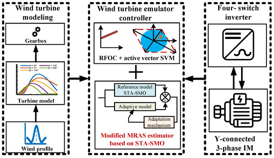
Before introducing the operating principles of the proposed control algorithms, it is necessary to establish a mathematical model for each component of the wind turbine emulator chain as illustrated by Figure 1.
Figure 1.
Proposed wind turbine emulator structure.
This modelling step provides the foundation for understanding, analyzing, and optimizing the overall conversion process from wind to mechanical energies to obtain reference speed or torque.
2.1. Wind Turbine Model
This subsystem contains the wind profile, the turbine geometry, and the gearbox.
2.1.1. Wind Profile
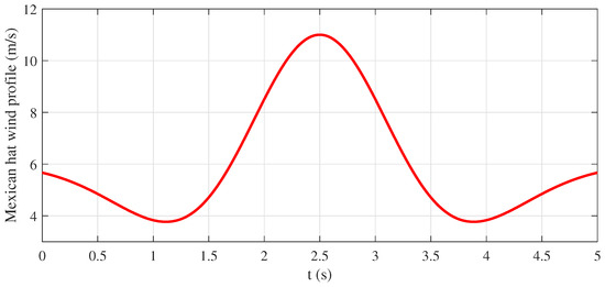
To evaluate the dynamic response of the proposed wind turbine emulator and its control scheme, an appropriate wind speed profile must first be defined. The wind profile depends on several parameters, including mean wind speed, direction, turbulence intensity, and vertical wind shear. In this study, a Mexican-hat wind speed profile is adopted as the input to the WTE, expressed as [39]:
where and are, respectively, the maximum (11 m/s) and average (6 m/s) wind speeds, is the burst center time (2.5 s), while ℓ represents its form factor (). The Mexican-hat profile is depicted by Figure 2.
Figure 2.
Mexican hat wind profile.
2.1.2. Turbine Model
As shown in Figure 1, a wind turbine is an electromechanical system that extracts kinetic energy from the wind and converts it into mechanical power at the rotor shaft. To represent and analyze this conversion process rigorously, the behavior of the horizontal-axis wind turbine considered in this study is described by the following set of mathematical equations [40]:
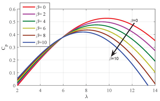
where is the turbine mechanical power, is the air density, A is the area swept by the turbine blades. denotes the power coefficient, a key indicator of wind turbine performance that characterizes its ability to convert the kinetic energy of the wind into mechanical (and ultimately electrical) power. This coefficient primarily depends on the tip-speed ratio and the blade pitch angle (in degrees), and can be expressed as follows:
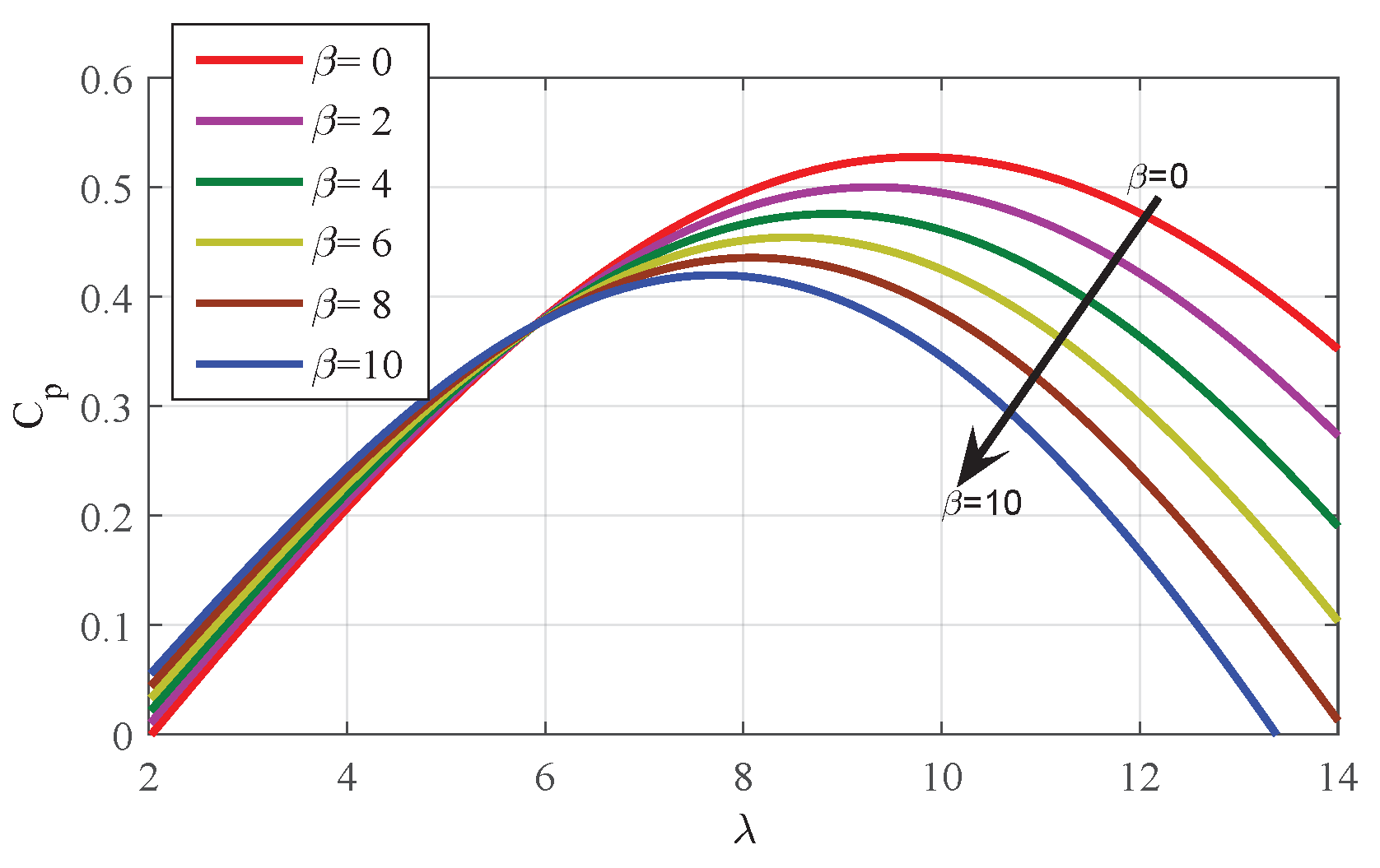
where . is the turbine angular velocity. Figure 3 shows that, in our study case, the reaches its maximum value at and an optimal tip-speed ratio of .
Figure 3.
- curves for different values.
The turbine torque is obtained by dividing the aerodynamic power by the turbine angular speed as:
2.1.3. Gearbox
The gearbox plays a key role in wind turbine operation by adapting the low rotor speed to the higher speed required by the generator for efficient electricity production. The rotor, driven by the wind, typically operates at relatively low angular velocities, whereas the generator must run at much higher speeds to deliver the desired electrical output. The gearbox provides this speed conversion by using an internal set of gears that increase the rotational speed while appropriately transforming the torque transmitted from the turbine shaft to the generator shaft. The I/O relationship of the gearbox in terms of speed and torque can be described by the following equation:
2.2. IM Model
The state–space representation of the induction motor can be formulated by selecting the stator current and the rotor flux as the state variables. Expressed in the stationary (, ) reference frame, the corresponding vector equations take the form:
where
In this formulation, , and , denote the stator current components and rotor-flux components, respectively. , represent the stator-voltage inputs in the frame. corresponds to the electrical rotor speed. and are the stator and rotor resistances. and denote the stator and rotor inductances. The mutual inductance is defined by M, and the dispersion coefficient is given by . p denotes the differential operator.
2.3. Four-Switch Inverter Model
In this study, the three-phase induction motor drive is supplied by a four-switch inverter, referred to as a Soft-VSI topology, consisting of four IGBTs and four antiparallel diodes.
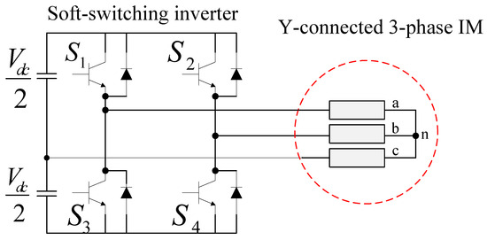
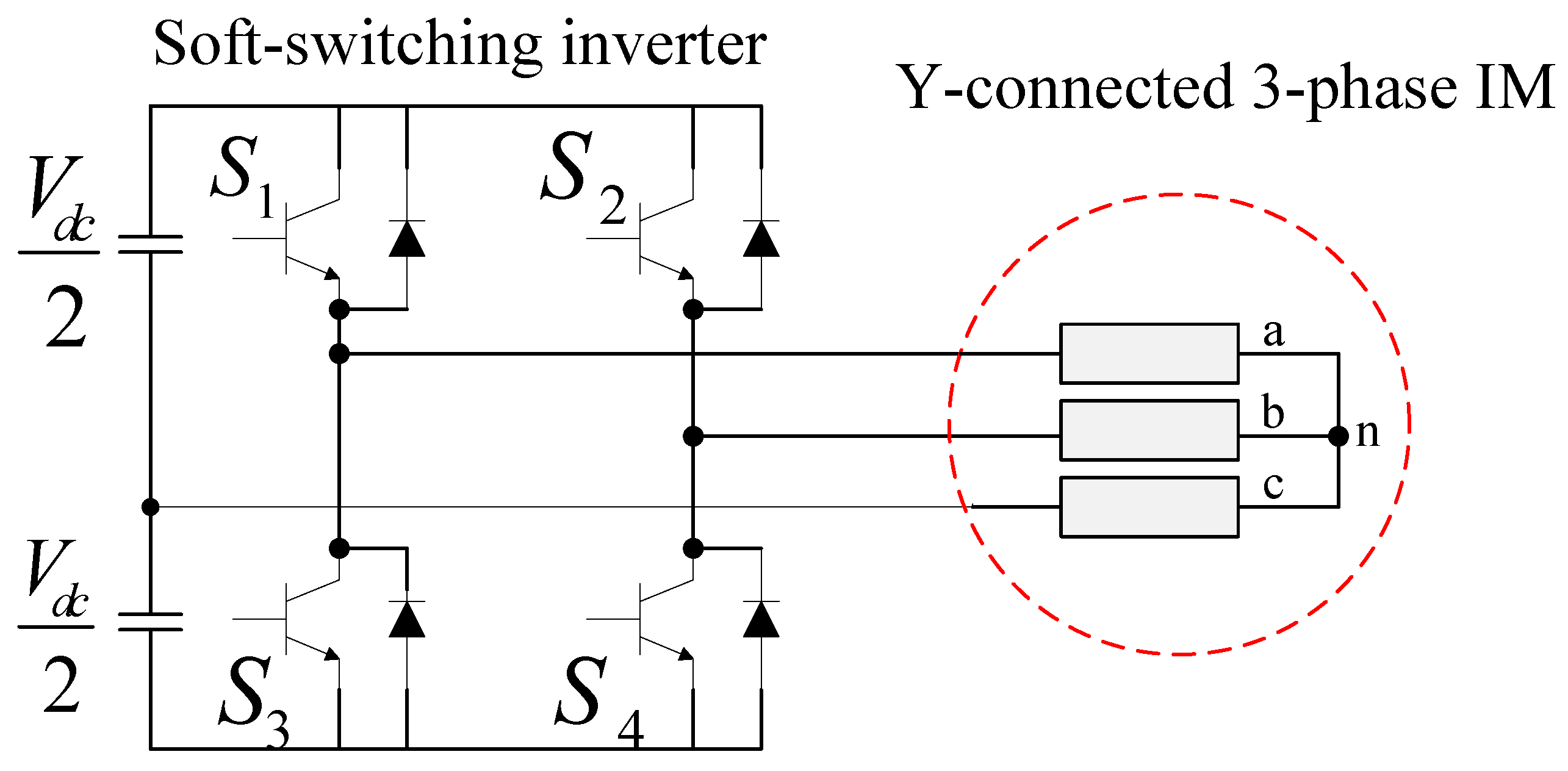
The use of this topology is motivated by its improved efficiency and reduced hardware complexity compared to a conventional six-switch VSI. By decreasing the number of active switching devices, the Soft-VSI reduces conduction and switching losses, alleviates thermal stress, and simplifies the gate-drive circuitry. These characteristics enhance overall system reliability and make the topology particularly suitable for laboratory-scale emulation platforms where cost-effectiveness, efficiency, and robustness are essential design constraints. Beyond device reduction, the DC-link structure plays a key role in ensuring stable inverter operation. The Soft-VSI employs a split DC-link composed of two series capacitors, which provide energy buffering while enabling the neutral point required for voltage synthesis. These capacitors must absorb instantaneous power fluctuations induced by inverter switching and dynamic load variations. Proper sizing is therefore necessary to limit the DC-link voltage ripple and maintain voltage stiffness, as excessive ripple may distort the synthesized motor voltages and degrade emulation accuracy. Additionally, maintaining voltage balance across the split capacitors is crucial; imbalance can introduce offset voltages, waveform distortion, and potential stability issues. Ensuring balanced operating conditions and appropriate capacitor design thus supports accurate voltage generation and reliable wind-turbine behavior emulation. In the adopted inverter–motor configuration, as shown in Figure 4, the midpoint of the split DC-link is connected to the stator windings through a Y-connected 3-phase IM, enabling the Soft-VSI to synthesize the required phase voltages using only four active switches.
Figure 4.
Three-phase IM soft-switching drive topology. Terminals a, b, and c denote the stator phase connections of the Y-connected induction motor, while n represents the neutral point. The red dotted circle highlights the Y-connected three-phase stator winding of the induction motor.
Under the assumption of ideal switches and a stiff DC-link across the two capacitors, the switching states are defined by , where 1 and 0 denote the closed and open states, respectively. The resulting line-to-line output voltages can then be expressed as:
Hence, for a balanced three-phase system, the generated line-to-neutral output voltages are:
Further details on the development and operating principles of this topology can be found in [41,42].
3. Proposed Super-Twisting Flux Observer Design
3.1. IM Observability
The observability of IM is a primordial condition for any sensorless estimation scheme, as only the stator currents are directly measurable while the rotor fluxes and mechanical speed remain internal. The system dynamics are expressed by the general non-linear form , and the measured output is , with . Local observability is classically assessed by investigating the rank condition of the non-linear observability matrix [43,44]. This matrix is constructed from the successive Lie derivatives of the output function along the system’s vector fields:
The IM is locally observable at an operating point if the matrix achieves full rank, i.e.,
The determinant of the observability matrix, , is used to identify the singular points where the system loses its discernibility property. Analysis of the non-linear dynamics reveals a critical dependency of the system’s observability on the electromagnetic coupling terms. The determinant of becomes zero, leading to a loss of observability, when the following conditions are simultaneously met [44,45]:
Given this limitation, a more robust estimation strategy is required in low-speed regions. In this work, this challenge is addressed by introducing a Super-Twisting Sliding Mode Observer (ST-SMO), designed to mitigate chattering effects while maintaining accurate flux and speed estimation in weakly observable operating regions.
3.2. Design of STA-SMO
The STA is part of the class of higher-order sliding mode techniques, specifically designed to ensure finite-time convergence of the sliding variable and its first time derivative. A key advantage of the STA is its capacity to significantly mitigate the chattering phenomenon—a primary drawback of conventional first-order sliding mode observers—by generating a quasi-continuous control action. We consider a differential system with bounded uncertainties, where the state is measurable. The objective is to drive the sliding variable and its time derivative to zero. The simplest canonical form of the STA, suitable for the estimation of a measurable state that depends on an auxiliary state and perturbation [43,44], is expressed as follows:
where and are the measured state and its estimate, respectively. is the standard sign function. and are the positive SM gains, represents the perturbation term. The robustness properties of this structure have been rigorously established in the literature by means of geometric analysis and Lyapunov-based arguments [46,47,48]. These results show that finite-time convergence of the estimation error is guaranteed when the perturbations entering the algorithm satisfy explicit global bounds. A widely adopted sufficient condition consists in:
where must be large enough to make the above-mentioned inequality be easily satisfied. Then the required finite-time convergence properties is guaranteed if the gains satisfy:
where is the Lipschitz’s constant [49].
3.3. STA-Based Rotor Flux Observer
Based on the STA structure introduced in (11), the induction machine model can be rearranged into a form that is explicitly compatible with the observer dynamics, as follows:
Thus, (14) is rewritten as:
For observer synthesis, it is convenient to introduce the change of variables:
As a result, Equation (15) becomes:
By applying the STA (11) to the IM model (17), a super-twisting observer for the stator currents is reconstructed as follows:
where , , , and are positive gains chosen by respecting the STA reachability condition given in (12) and (13). , are the -axis and -axis stator current observation errors, respectively.
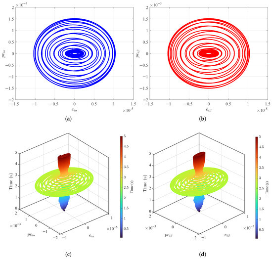
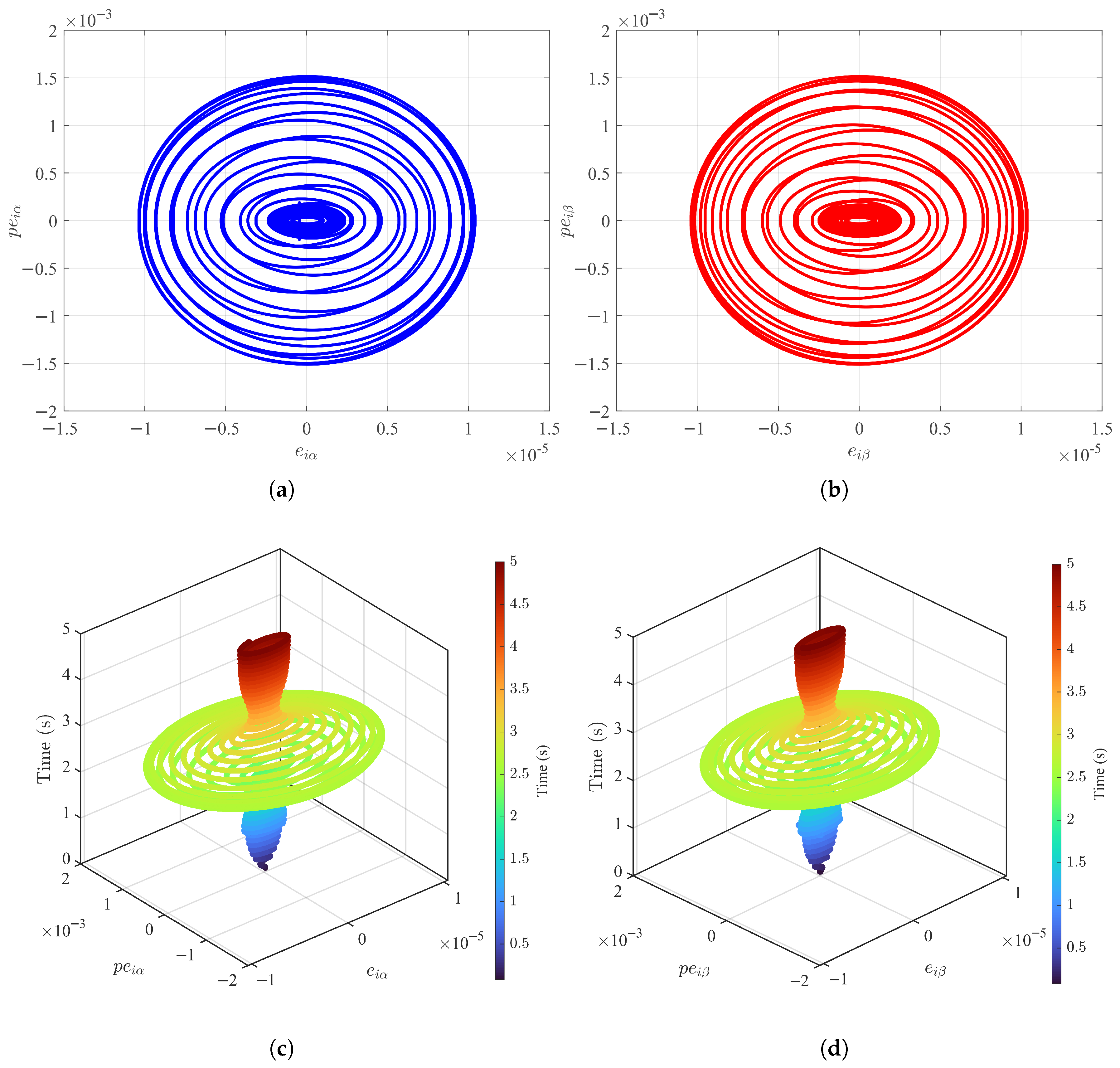
In practice, the STA gains are chosen to satisfy the sufficient reachability conditions with conservative margins to ensure robustness against modeling uncertainties and bounded perturbations, and their final values are validated numerically to limit control effort while preserving finite-time convergence. Figure 5 illustrates the phase-portrait analysis of the proposed super-twisting sliding-mode observer. The error dynamics in the and planes are illustrated in Figure 5a,b, showing smooth spiraling trajectories that converge toward the equilibrium point.
Figure 5.
Phase-portrait analysis of the proposed super-twisting sliding-mode observer: (a) error dynamics in the plane. (b) error dynamics in the plane. (c) 3D convergence regions highlighting the finite-time contraction of toward the origin. (d) 3D convergence regions highlighting the finite-time contraction of toward the origin.
The 3D convergence regions in Figure 5c,d provide a clearer view of the finite-time convergence characteristic of second-order sliding modes. The absence of chattering or limit cycles validates the theoretical robustness and global stability of the observer.
4. Sensorless Control
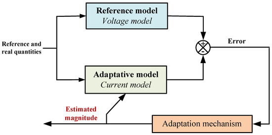
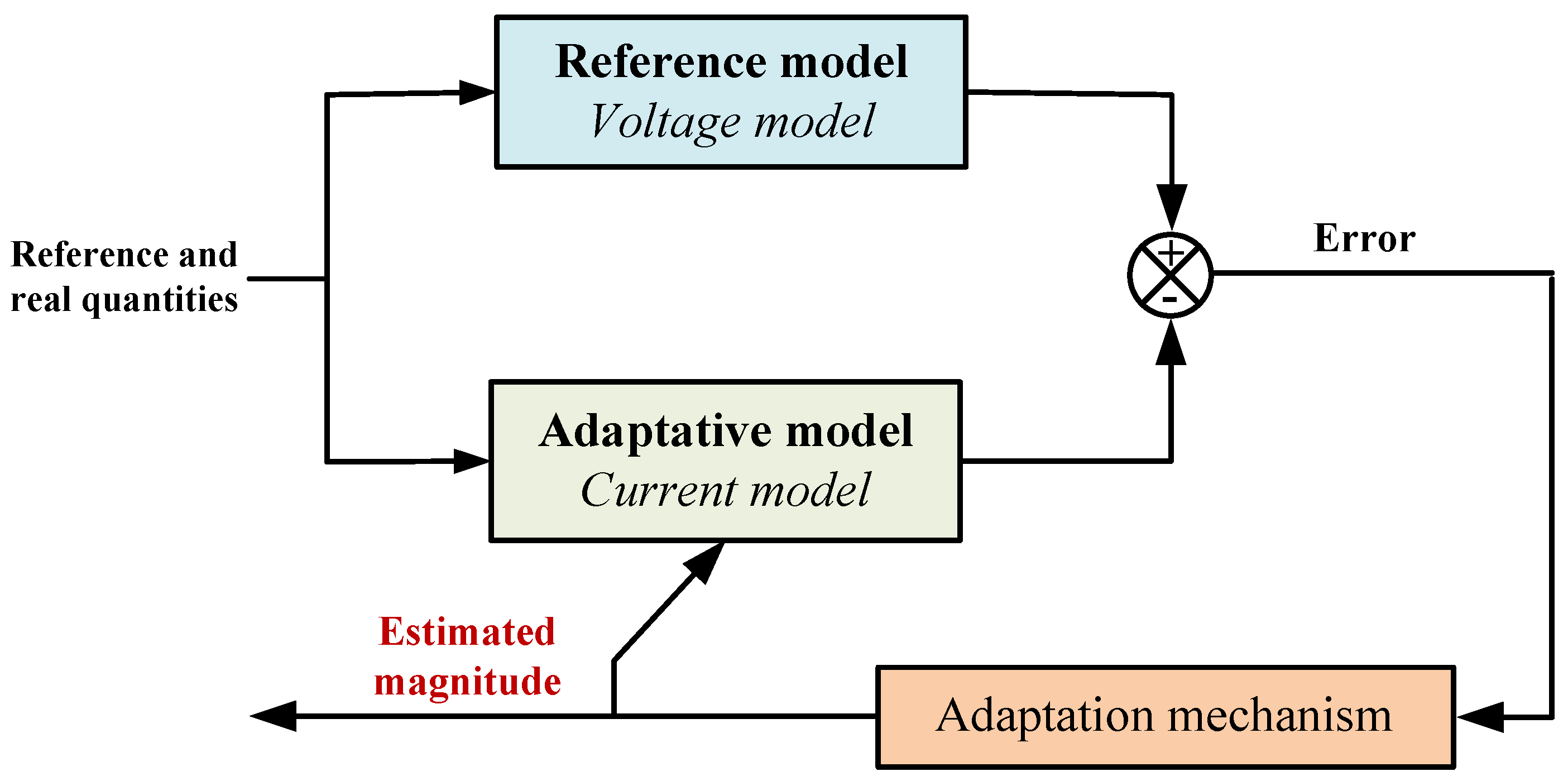
In sensorless induction motor drives, the MRAS remains one of the most widely adopted methods for speed estimation, owing to its simple structure and real-time feasibility. Conventional MRAS schemes, as illustrated in Figure 6, typically rely on a current model and a voltage model, where the latter, used as the reference model, suffers from poor robustness under parameter uncertainties, most notably rotor-resistance variations. This structural limitation induces biased flux estimates, especially at low stator frequencies, and often leads to degraded speed adaptation or divergence of the control loop.
Figure 6.
Block diagram of conventional MRAS estimator.
To overcome these limitations, the present work introduces a modified MRAS architecture in which the reference model is no longer derived from the classical linear flux model but is instead generated through a super-twisting algorithm-based flux observer, while the adaptive model derives its prediction from the machine equations parameterized by the estimated rotor speed.
Let the rotor-flux vector reconstructed by the STA be denoted by:
which serves as the reference model of the MRAS. The adaptive model is constructed from the classical current-model flux equations,
Since the model in (21) depends on the rotor speed variable, and is treated as a fixed parameter, the observer dynamics can be reorganized to yield the following estimation model:
where
and are respectively the actual and estimated rotor flux vectors calculated by the current model.
4.1. State–Error Dynamics
Defined by and respectively the observation error on the current and the observation error on the flux, formulated as follows:
Assuming high precision of the stator current acquisition’s digital processing, the observation of these quantities yields no observation errors (). Therefore, subtracting (21) from (22) yields nonlinear error dynamics, given by
where denotes the rotor speed error. By setting the matix by , Equation (24) can be rewritten in the following manner:
4.2. Hyperstability and Popov Criterion
To ensure convergence, the analysis relies on Popov’s hyperstability criterion. By defining suitable auxiliary variables, the Popov function can be expressed as an inner product between the error vector and the nonlinear feedback term:
where
is a positive constant. Substituting for and in this inequality by their expressions, Popov’s criterion for the present system becomes:
The inequality condition associated with this function satisfies a finite negative limit, which establishes a sufficient criterion guaranteeing stability of the estimation scheme. Equation (28) can be rearranged as:
where
Once the condition (29) is satisfied, an admissible adaptation rule for the rotor-speed estimate emerges naturally.
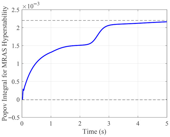
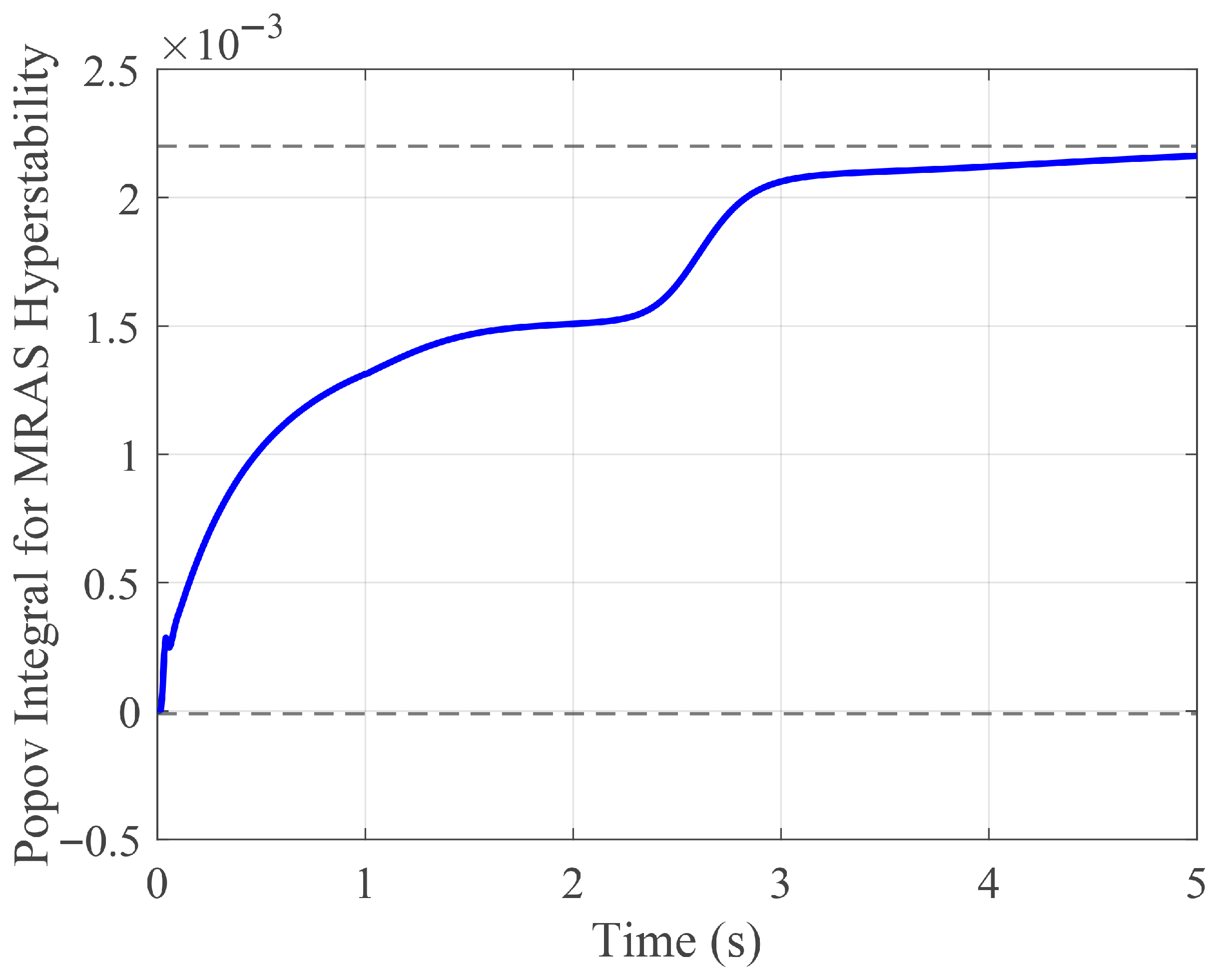
The hyperstability of the proposed MRAS–STA scheme is numerically assessed through the Popov integral associated with the speed adaptation mechanism. As shown in Figure 7, the integral of the product between the MRAS error signal and the estimated rotor speed remains bounded over the entire operating range, thereby satisfying Popov’s inequality. This result confirms that the nonlinear adaptation law does not inject energy into the estimation loop and guarantees the global stability of the speed estimation process.
Figure 7.
Popov Integral for MRAS Hyperstability. The dotted lines indicate the admissible bounds of the Popov integral, showing that it remains within a bounded region and thus satisfies Popov’s inequality.
Although the MRAS adaptive gains are analytically derived using Popov’s hyperstability criterion, their practical influence on convergence speed and robustness is assessed through simulation. The results demonstrate that the proposed MRAS–STA estimator maintains stable operation and convergence over a wide range of gain values, indicating low sensitivity to moderate tuning variations.
4.3. Speed-Adaptation Law
In the proposed speed estimation scheme, the output of the MRAS reference model, which is based on the STA-SMO, is regarded as equal to the actual rotor flux vector.
within this condition, the rotor speed-adaptation mechanism can be derived by the following expression:
To improve the convergence of the proposed scheme, the proportional integral adaptive law is adopted as follows:
where and are determined based on [50], as:
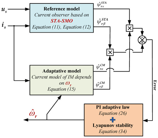
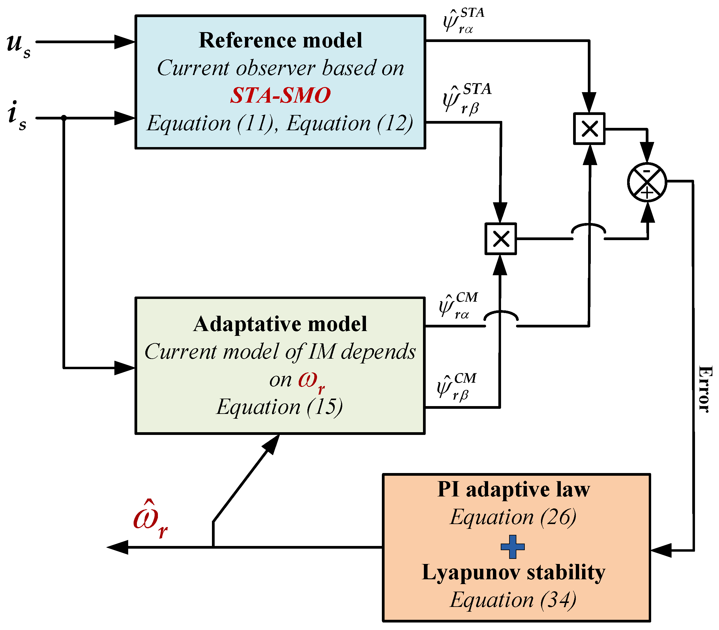
where is the damping factor fixed to and is the natural angular velocity. The overall block diagram of the speed estimation scheme based on STA-SMO combined with a modified MRAS estimator is shown in Figure 8.
Figure 8.
Block diagram of the proposed STA–SMO combined with a modified MRAS estimator.
4.4. Lyapunov Stability of the Proposed MRAS–STA Scheme
For stability assessment, a quadratic Lyapunov function is constructed using the flux-error components and the speed-error term:
with a scalar constant to be chosen. Using (25) and (33), its derivative with respect to time is:
The Lyapunov derivative Function (36) must be forced to be strictly negative to ensure asymptotic stability. Substituting (25) in (36), the inequality can be rewritten as follows:
by cancelling in Equation (37), we can write:
where is the rotor flux error module. During the short sampling interval of the drive system, the mechanical speed can be treated as constant, which means . So:
By substituting by its adaptation mechanism, (39) can be rearranged as follows:
Choosing cancels the cross term, giving:
As a result, (41) is negative semi-definite. Under standard MRAS assumptions (bounded signals, persistent excitation of the flux), LaSalle’s invariance principle implies:
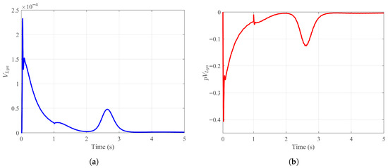
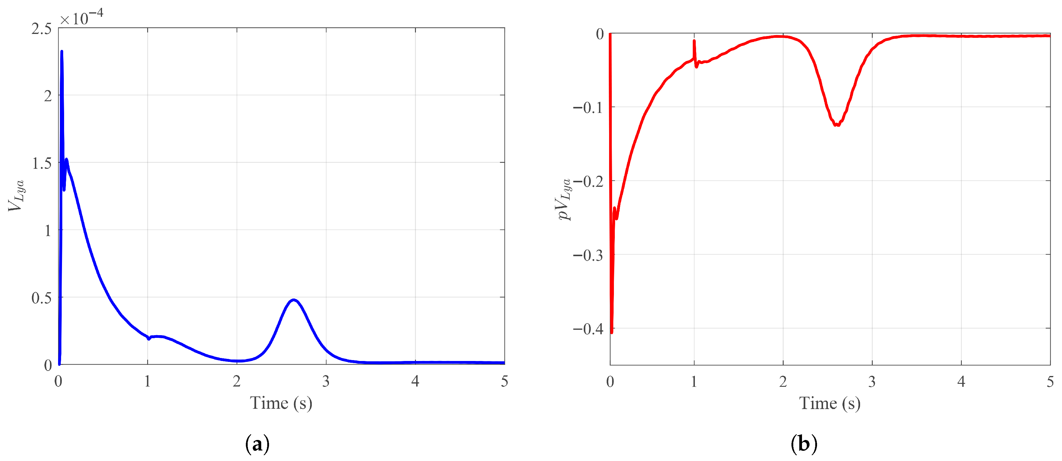
Thus the MRAS–STA speed estimator is globally asymptotically stable. Figure 9 illustrates the time evolution of the Lyapunov candidate function and its time derivative for the proposed MRAS–STA observer.
Figure 9.
Lyapunov Stability of the Proposed MRAS–STA Scheme: (a) . (b) .
As shown in Figure 9a, the Lyapunov function remains strictly positive and decreases monotonically toward zero despite transient perturbations, which confirms that the estimation error dynamics are bounded and converge asymptotically. Moreover, Figure 9b demonstrates that the derivative of the Lyapunov function is negative semi-definite over the entire operating interval, except for negligible transient fluctuations induced by speed variations. This behavior satisfies the Lyapunov stability conditions and confirms that the proposed MRAS–STA scheme guarantees global asymptotic stability of the rotor speed estimation.
5. Simulation Test Validation
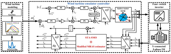
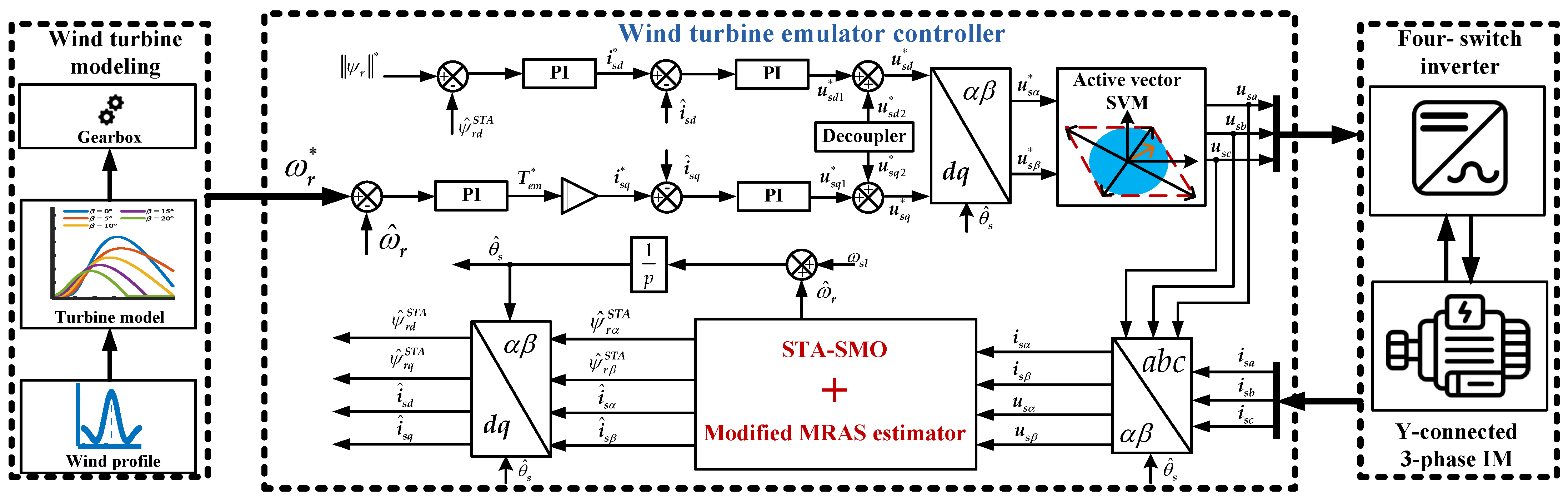
To verify the theoretical developments and to assess the effectiveness of the proposed sensorless control strategy, extensive numerical simulations were carried out using the MATLAB/Simulink environment. The WTE system consists of an induction motor operating under field-oriented control, in which rotor flux and speed are estimated by a modified MRAS scheme incorporating an STA-based sliding-mode observer as the reference model. The block diagram of the overall WTE controller design is shown in Figure 10.
Figure 10.
Overall architecture scheme of the proposed sensorless vector control strategy for the wind turbine emulator.
The parameters of the wind turbine and the induction motor considered for the design and validation of the proposed STA–MRAS–based sensorless control strategy are listed in Table 1 and Table 2.
Table 1.
Wind Turbine Parameters.
Table 2.
Induction Motor Parameters.
The performance of the proposed MRAS–STA observer is evaluated under a non-stationary operating condition characterized by a Mexican-hat speed profile, which imposes simultaneous acceleration and deceleration phases. This excitation is particularly suitable for testing the convergence, robustness, and transient behavior of sensorless observers. For a fair and meaningful comparison, the same operating conditions, control parameters, and speed profile are maintained when evaluating the proposed approach against the FO-SMO previously reported in [39].
5.1. Validation of the Proposed MRAS–STA Sensorless Control Scheme
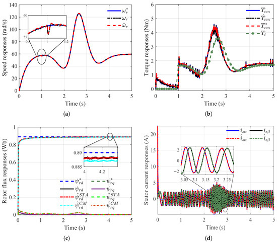
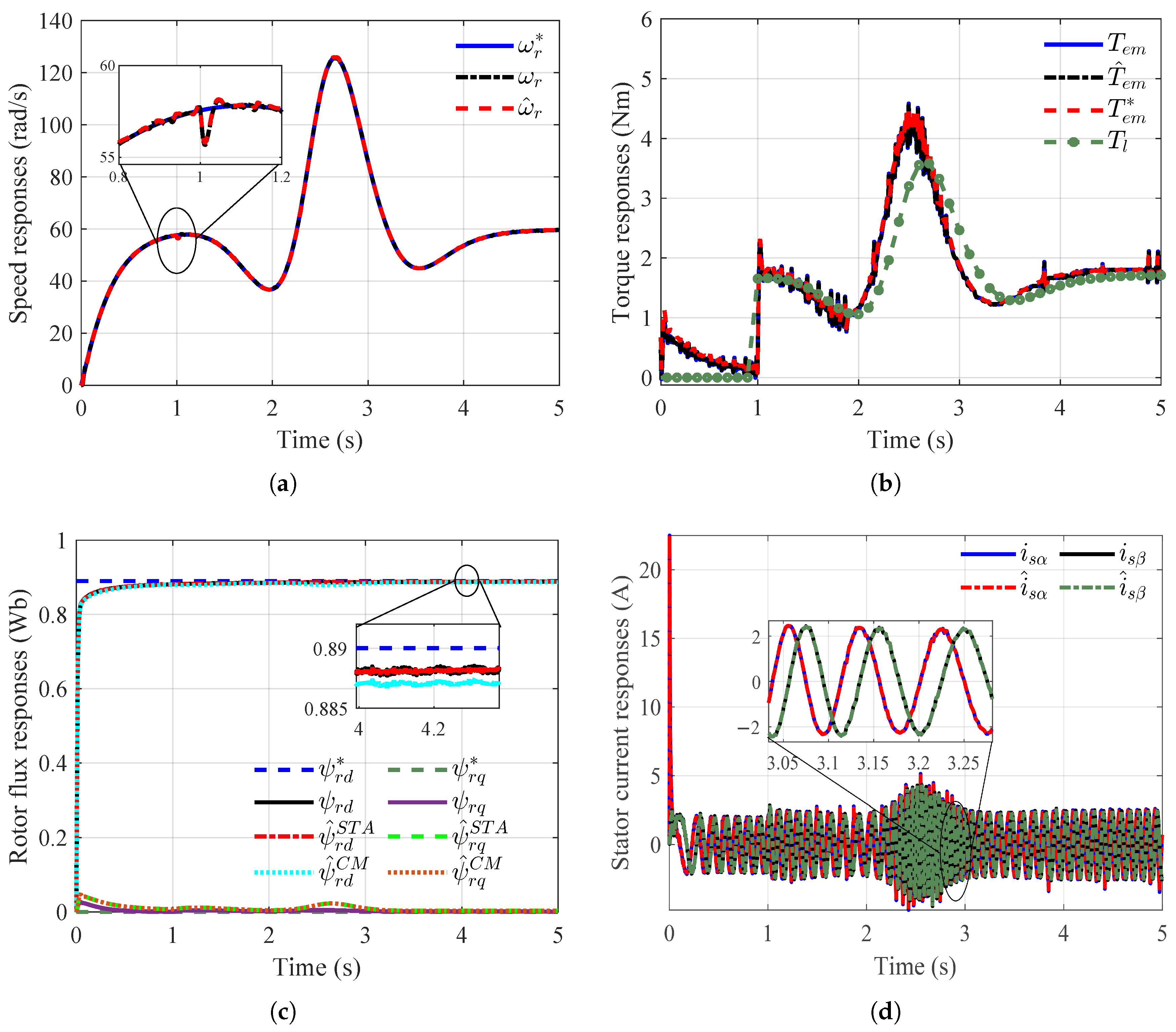
This subsection aims to validate the proposed sensorless control architecture based on the combination of a super-twisting sliding-mode flux observer and an MRAS-based speed adaptation mechanism. The WTE system is initially operated under no-load conditions. At s, a load torque proportional to the rotor speed is applied to the proposed wind turbine emulator in order to evaluate the dynamic performance of the control scheme. Subsequently, to assess the robustness of the proposed sensorless control strategy against parametric uncertainties, a sudden increase of in the rotor resistance is introduced at s.
Figure 11a depicts the reference speed, the real rotor speed, and the estimated speed generated by the proposed MRAS–STA scheme. During no-load operation, the estimated speed accurately tracks the reference with negligible steady-state error. Following the application of the speed-dependent load torque at s, the estimator preserves fast convergence and closely follows the transient dynamics. The rotor resistance variation introduced at s does not induce any divergence or noticeable deviation in the estimated speed, thereby confirming the robustness of the modified MRAS structure in which the super-twisting observer acts as the reference model. Figure 11b illustrates real, reference, and estimated electromagnetic torque and the applied load torque. The proposed control scheme ensures smooth torque generation with limited overshoot during both load application and parameter variation. The torque response remains well regulated despite the abrupt increase in rotor resistance, highlighting the strong disturbance rejection capability provided by the STA-based flux estimation and the robustness of the sensorless control loop. Figure 11c presents the real and reference rotor flux components, as well as the flux estimated by the proposed STA-based observer and by the current model. The close tracking behavior between the estimated flux trajectories confirms accurate flux reconstruction. Minor transient deviations observed during the load torque application rapidly vanish, and no degradation is observed after the rotor resistance variation, demonstrating the finite-time convergence and parametric robustness of the STA flux observer. Figure 11d shows the stator current components in the stationary reference frame. The currents remain sinusoidal and well-balanced throughout the entire operating scenario. Even during load application and rotor resistance variation, no excessive oscillations or distortion are observed, indicating that the proposed sensorless control strategy preserves high-quality current regulation and stable vector control performance. These results confirm that the proposed STA–MRAS-based sensorless control scheme achieves accurate speed and flux estimation, robust torque regulation, and stable current dynamics under both load disturbances and severe parameter uncertainties, thereby validating the theoretical developments and demonstrating its suitability for wind turbine emulator applications.
Figure 11.
Dynamic validation of the proposed STA–MRAS–based sensorless control scheme under load and parameter variation: (a) reference, real, and estimated rotor speed. (b) reference, real, estimated, and load torque responses. (c) rotor flux components and flux magnitude estimated by the STA-based observer and the current model. (d) stator current responses in the stationary reference frame.
5.2. Evaluation of the Proposed MRAS–STA Sensorless Control Under Low-Speed Operation
To further assess the robustness of the proposed sensorless strategy under operating conditions where classical MRAS observers generally lose observability, two low-speed test scenarios were conducted. The tests aim to demonstrate the stability of the flux estimation, the continuity of the speed adaptation, and the resilience of the STA-based flux observer against weak electromagnetic excitation and rotor resistance variations.
5.2.1. Scenario 1: Low–Speed and Very–Low Speed Operation
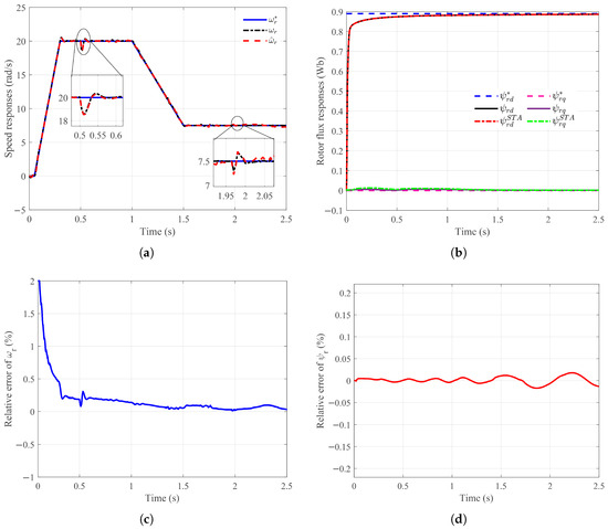
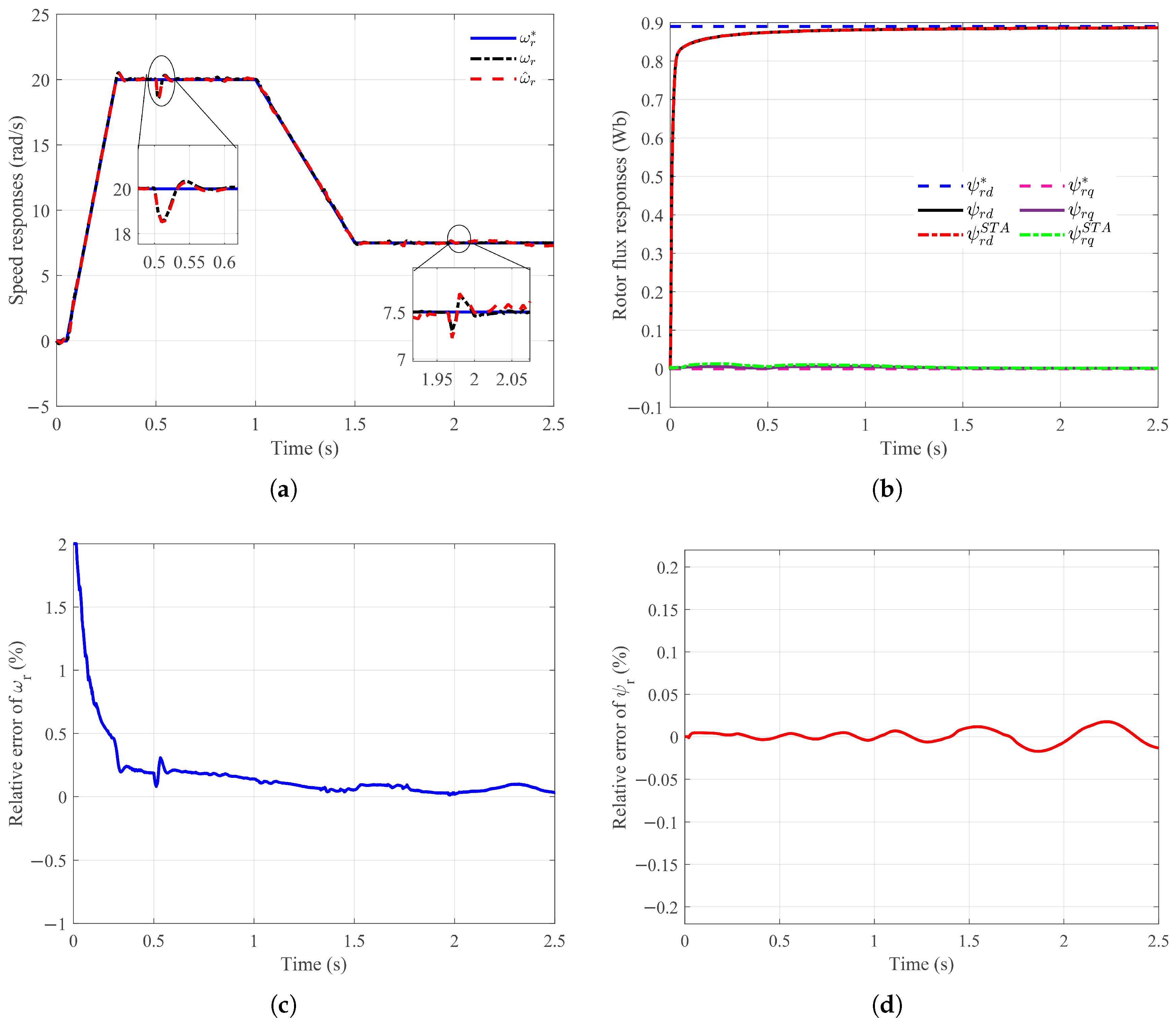
In the first scenario, the proposed sensorless control scheme is evaluated during a complete transition from standstill to low speed and then toward very-low-speed operation. The test begins with a short magnetization interval (0–0.05 s), during which the rotor flux is established. The motor is subsequently accelerated to 20 rad/s between s and s, and this speed is maintained until 1.0 s to assess steady low-speed performance. During this interval, at s, a load torque proportional to the rotor speed is applied in order to emulate realistic aerodynamic loading. After, the reference speed is decreased from 20 rad/s to 7.5 rad/s over the interval 1.0–1.5 s, corresponding to approximately of the rated speed. The machine then operates at this very low speed until s. To assess robustness under parameter mismatch, a increase in rotor resistance is introduced at s, while the machine continues to operate under load at very low speed. Figure 12a–d illustrate the real, estimated, and reference speeds, the estimated rotor flux components, and the relative estimation errors.
Figure 12.
Performance under low- and very-low-speed operation: (a) reference, real, and estimated rotor speed. (b) rotor flux components and flux magnitude estimated by the STA-based observer (c) rotor speed error. (d) rotor flux magnitude error.
Despite the weak back-EMF in this speed region, the proposed STA–MRAS observer maintains smooth flux trajectories and accurate speed reconstruction. The relative flux and speed errors remain bounded and do not exhibit divergence following the perturbation, demonstrating the finite-time convergence and robustness of the STA mechanism.
5.2.2. Scenario 2: Zero-Speed Operation
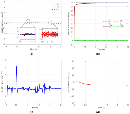
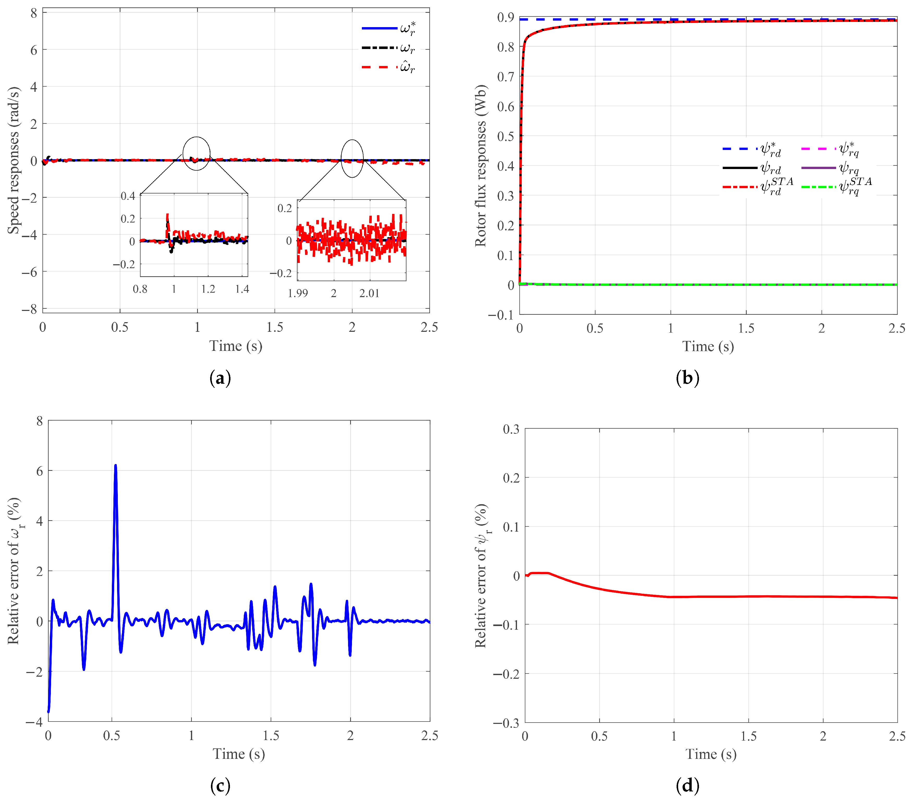
In the second scenario, the reference speed is maintained at 0 rad/s for the entire time interval (0–1.5 s). A load torque proportional to speed is applied at s, and a rotor resistance variation is introduced at s. Figure 13a–d report the speed, flux, and relative error profiles. The proposed strategy successfully maintains stable flux orientation and ensures non-singular speed estimation, even in the absence of measurable back-EMF. Importantly, the STA flux observer prevents drift in the stator current dynamics, enabling the MRAS mechanism to preserve observability at standstill. These results confirm the suitability of the proposed sensorless control for wind turbine emulator applications requiring zero-speed torque generation and slow-wind operating conditions.
Figure 13.
Performance under zero-speed operation: (a) reference, real, and estimated rotor speed. (b) rotor flux components and flux magnitude estimated by the STA-based observer (c) rotor speed error. (d) rotor flux magnitude error.
5.3. Comparative Assessment with the First-Order SMO Scheme
To further highlight the advantages of the proposed STA-based observer combined with an MRAS speed adaptation mechanism, a comparative analysis is carried out against the first-order sliding-mode observer introduced in our previous work [39]. Both observers are evaluated under identical operating conditions and subjected to the same Mexican-hat speed profile to ensure a fair and objective comparison. The relative estimation error for a generic variable is defined as:
The evaluation is carried out in two stages. First, the robustness of both observers is analyzed without any adaptation mechanism when a sudden increase in rotor resistance is introduced at s. Subsequently, the FO-SMO is enhanced with a Lyapunov-based adaptation law, while the proposed STA-SMO operates without explicit rotor resistance adaptation.
5.3.1. Performance Comparison Without Parameter Adaptation
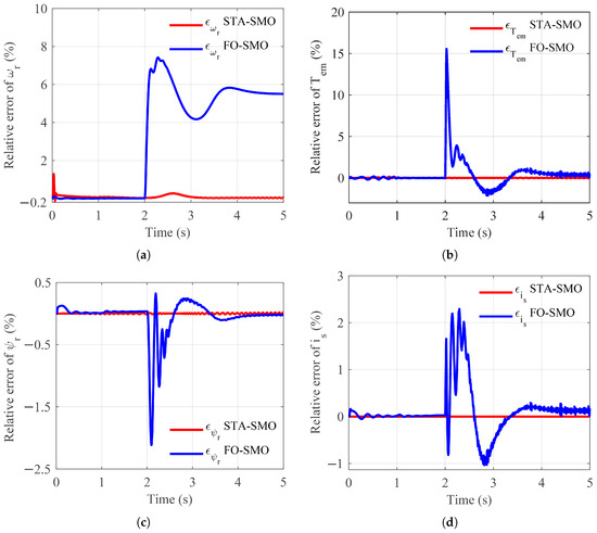
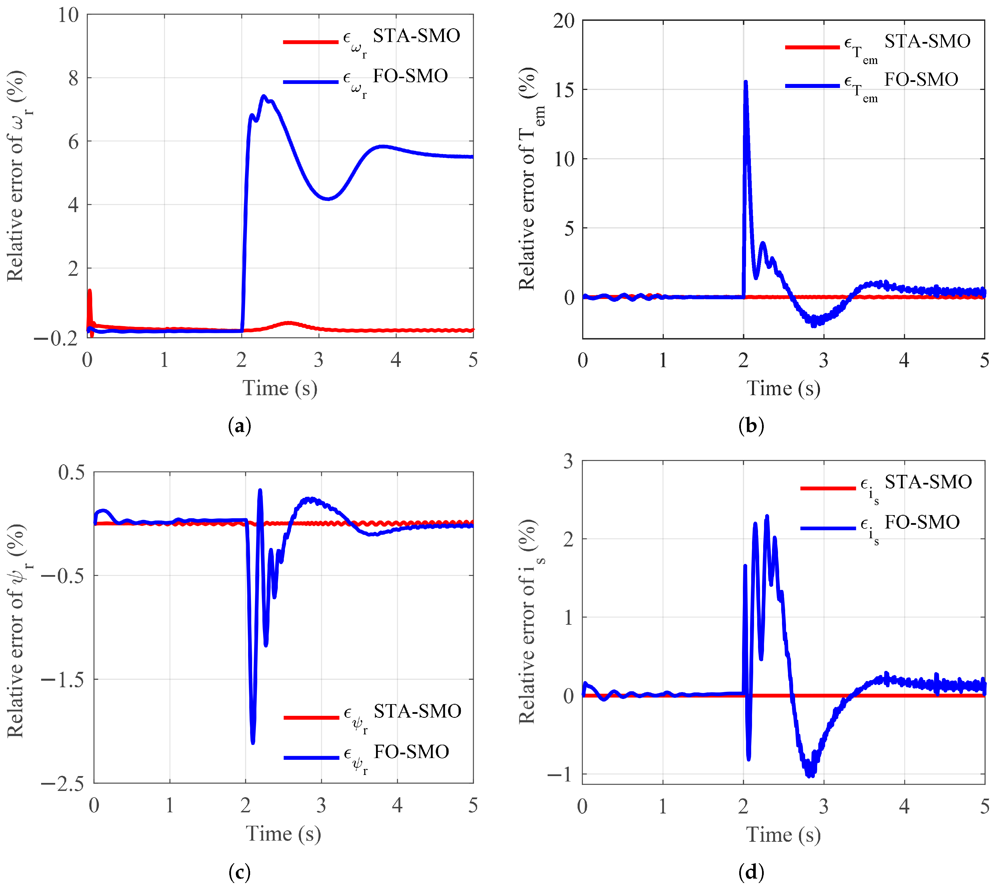
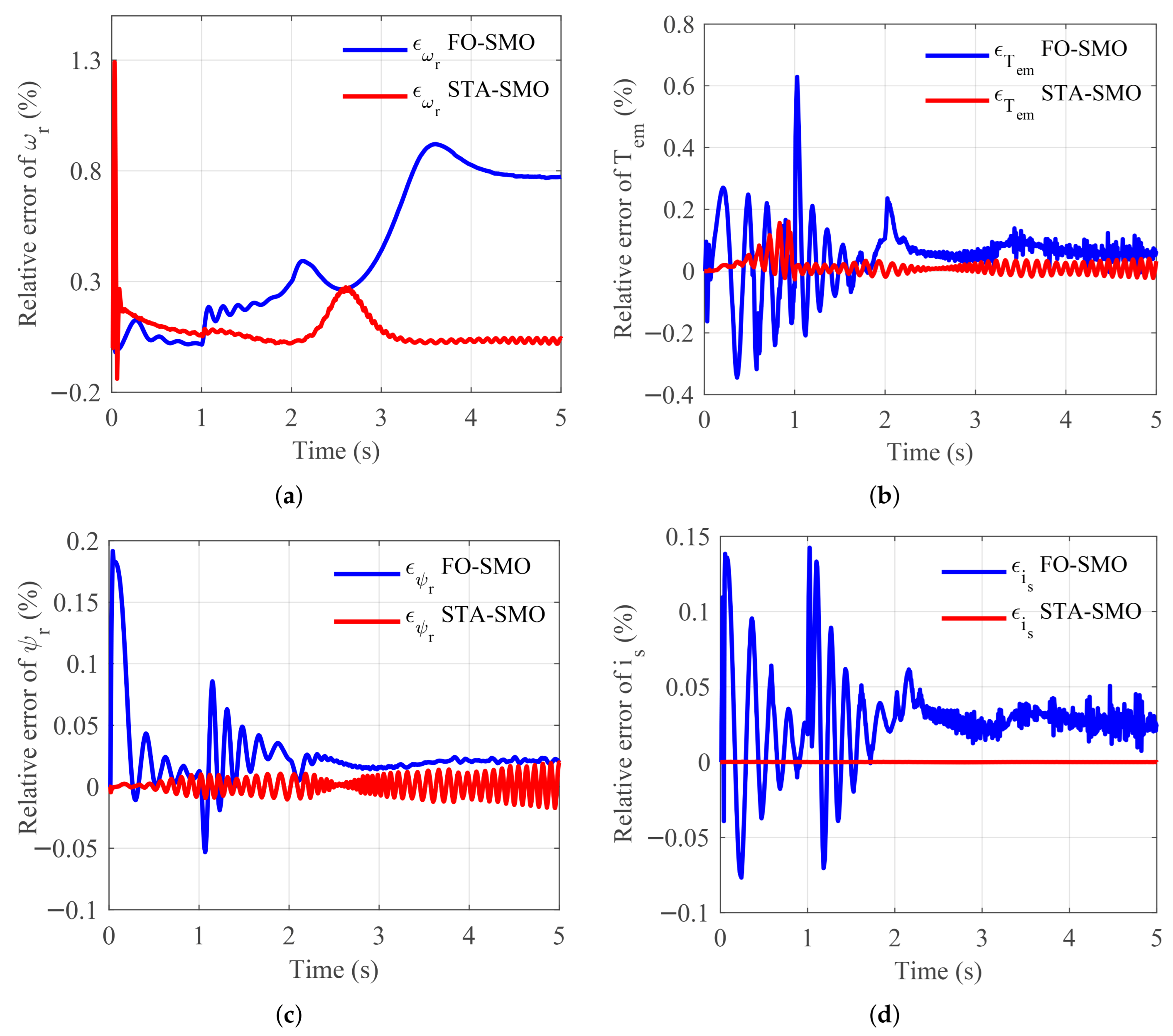
Figure 14 illustrates the relative estimation errors of rotor speed, electromagnetic torque, rotor flux magnitude, and stator current magnitude without any adaptation mechanism.
Figure 14.
Time evolution of the relative estimation errors obtained using the proposed STA-SMO and the FO-SMO in the presence of a rotor resistance increase at s, without any parameter adaptation mechanism: (a) rotor speed error. (b) electromagnetic torque error. (c) rotor flux magnitude error. (d) stator current magnitude error.
As can be seen in Figure 14a, the FO-SMO is highly sensitive to variations in rotor resistance, resulting in significant transient deviations and steady-state errors in estimated speed. By contrast, the proposed STA-SMO maintains bounded error with rapid convergence, confirming its superior robustness to parametric uncertainty. A similar trend is observed in Figure 14b for the electromagnetic torque estimation. The FO-SMO generates substantial oscillations and a higher peak error following the parameter variation, whereas the STA-SMO ensures smoother dynamics with reduced overshoot. Figure 14c,d further demonstrate that rotor flux and stator current estimations obtained with the FO-SMO are severely affected by the resistance mismatch, leading to oscillatory behavior and delayed convergence. Conversely, the STA-SMO preserves accurate estimation with limited error magnitude, highlighting the benefit of the super-twisting algorithm in mitigating chattering and enhancing robustness.
5.3.2. Impact of Rotor Resistance Adaptation on Estimation Accuracy
Figure 15 illustrates the estimation errors when a Lyapunov-based adaptation mechanism for rotor resistance is introduced in the FO-SMO, while the STA-SMO operates without rotor resistance adaptation. As shown in Figure 15a, the adaptation mechanism significantly improves the FO-SMO speed estimation by reducing steady-state error. However, noticeable oscillations persist during transients. In contrast, the STA-SMO continues to deliver smoother and more accurate speed estimation with faster convergence. Figure 15b–d reveal that, despite adaptation, the FO-SMO still suffers from residual oscillations in torque, flux, and current estimation, particularly during the transient phase following the resistance variation. The proposed STA-SMO consistently achieves lower error amplitudes and improved damping, demonstrating that its robustness originates from the observer structure itself rather than from parameter adaptation.
Figure 15.
Time evolution of the relative estimation errors obtained using the proposed STA-SMO (without rotor resistance adaptation) and the FO-SMO equipped with a Lyapunov-based adaptation mechanism, under a rotor resistance increase at s: (a) rotor speed error. (b) electromagnetic torque error. (c) rotor flux magnitude error. (d) stator current magnitude error.
5.3.3. Quantitative Comparison of Estimation Accuracy
Although time-domain waveforms offer qualitative insights into the dynamic behavior of the observer schemes, a quantitative comparison based on the Root Mean Square Error (RMSE) and maximum absolute relative error is required to objectively compare the estimation accuracy of the proposed MRAS–STA approach with the FO-SMO. The error indices are defined as:
where N is the total number of samples within the considered operating interval. The evaluation is conducted over three distinct operating phases: no-load operation, load torque application, and rotor resistance variation. The resulting quantitative metrics for both observer schemes are summarized in Table 3.
Table 3.
Quantitative comparison of estimation accuracy using RMSE and maximum absolute relative error under different operating conditions.
The results clearly indicate that the proposed MRAS–STA observer consistently achieves lower and values across all operating conditions and for all estimated variables. In particular, under rotor resistance variation, the FO-SMO exhibits a pronounced degradation in estimation accuracy, reflected by a significant increase in both error indices. In contrast, the MRAS–STA scheme maintains bounded estimation errors with only marginal performance deterioration, confirming its enhanced robustness to parametric uncertainties. Moreover, even when the FO-SMO is augmented with a rotor resistance adaptation mechanism, the proposed MRAS–STA approach retains superior accuracy, especially during transient regimes following load application and parameter variation. This improvement can be attributed to the finite-time convergence and reduced chattering of the STA observer, which provides a more reliable flux reference for the MRAS speed adaptation loop.
The quantitative results and the qualitative observations demonstrate that the proposed MRAS–STA sensorless control scheme offers a substantial improvement in estimation accuracy and robustness compared to the conventional first-order SMO approach, even when the latter is enhanced with an adaptation mechanism.
5.4. FPGA Implementation Roadmap and HIL Deployment
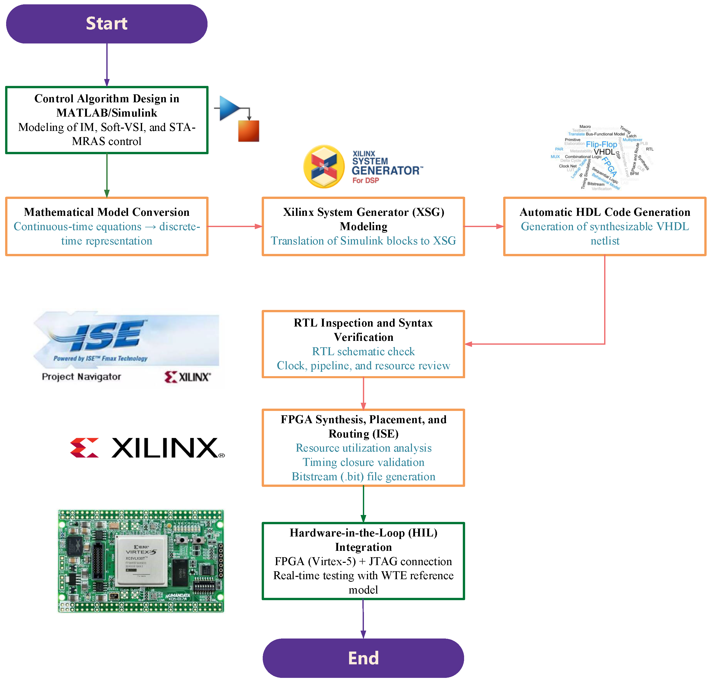
To ensure real-time implementation of the proposed control strategy, a complete FPGA-based HIL implementation has been planned and partially executed. The wind turbine emulator platform under development includes a reduced 4S–VSI, a power acquisition board, a control board, and two Xilinx Virtex-5 XC5VLX50T FPGA modules that will include the control algorithm. The first step toward real-time validation consists of remodelling the entire STA-based SMO and MRAS speed estimation scheme using Xilinx System Generator (XSG) blocks. This translation ensures numerical consistency with Simulink simulations while satisfying hardware constraints such as fixed-point precision, clock-synchronized pipelines, and logic resource limitations. Since several mathematical functions (e.g., square-root, trigonometric computations) are not directly available in XSG, custom high-accuracy blocks have been designed to reproduce the Simulink behavior within FPGA-compatible architectures. Once the XSG model is verified, the platform automatically generates VHDL code for FPGA synthesis. The Xilinx Integrated Synthesis Environment (ISE) is then used to perform RTL verification, resource estimation, place-and-route, and bitstream generation. The final file will be deployed on the two-FPGA architecture, enabling a closed-loop HIL setup wherein the master FPGA performs the machine parameter estimation using the STA–MRAS scheme, while the slave FPGA executes the FOC and real-time acquisition of the induction motor parameters. This configuration will allow extensive validation of timing determinism, observer robustness, FPGA resource utilization, and dynamic performance under parameter uncertainties. The whole process of practical FPGA-based implementation is summarized in Figure 16.
Figure 16.
Practical FPGA-based implementation of the proposed sensorless Soft-VSI induction motor drive for wind turbine emulation.
This roadmap establishes the feasibility of the proposed methodology for future hardware deployment and forms the foundation of the forthcoming experimental stage.
6. Conclusions
This paper has proposed a robust sensorless vector control scheme for a three-phase induction motor drive supplied by a reduced-switch Soft–VSI topology, specifically designed for wind turbine emulator applications. The proposed architecture integrates a super-twisting sliding-mode flux observer with an enhanced MRAS speed estimation scheme, where the reference model is generated from the STA-observed flux rather than a classical linear model. This modification significantly improves robustness to parameter variations and yields accurate estimation performance, particularly in operating regions where conventional MRAS approaches are prone to divergence. The stability of the proposed MRAS–STA architecture has been rigorously ensured through hyperstability arguments, Popov’s criterion, and Lyapunov-based analysis. The results of simulation experiments conducted under no-load operation, load disturbances, severe rotor resistance variation, and low-speed and very-low-speed operation demonstrate finite-time convergence of the observer, accurate speed tracking, and consistently bounded estimation errors. The additional results confirm that the proposed scheme maintains full observability and dynamic robustness even at zero and near-zero speed, which are among the most challenging conditions for induction-motor-based emulation systems. A comparative assessment against a first-order sliding-mode observer highlights the superior performance of the proposed super-twisting formulation in terms of chattering reduction, flux smoothness, and estimation accuracy. Furthermore, a practical FPGA implementation roadmap and an HIL deployment strategy have been outlined, demonstrating that the proposed method is compatible with real-time constraints and ready for future experimental validation.
The presented sensorless Soft-VSI drive architecture constitutes an efficient, reliable, and computationally lightweight solution for next-generation wind turbine emulators. Its robustness, low-speed capability, and real-time implementation readiness make it a strong candidate for cost-sensitive renewable energy research platforms, educational systems, and industrial prototyping environments.
Author Contributions
Conceptualization, M.Z. and I.M.; methodology, M.Z.; software, M.Z.; validation, M.Z., I.M., and A.K.; investigation, M.Z. and I.M.; writing—original draft preparation, M.Z. and I.M.; writing—review and editing, A.K.; visualization, M.Z., I.M., and A.K.; supervision, I.M. and A.K. All authors have read and agreed to the published version of the manuscript.
Funding
This research received no external funding.
Institutional Review Board Statement
Not applicable.
Informed Consent Statement
Not applicable.
Data Availability Statement
The original contributions presented in this study are included in the article. Further inquiries can be directed to the corresponding author.
Conflicts of Interest
The authors declare no conflict of interest.
References
- López-López, P.; Estellés-Domingo, I.; Gil, J.A. Wind energy and species reintroductions: A call to action for adaptive conservation planning. J. Environ. Manag. 2026, 397, 128266. [Google Scholar] [CrossRef] [Scilit]
- Global Installed Wind Energy Capacity 2023. Statista 2024. Available online: https://www.statista.com/statistics/268363/installed-wind-power-capacity-worldwide/ (accessed on 1 December 2024).
- Ember. Energy Institute—Statistical Review of World Energy 2024. Our World in Data. Available online: https://ourworldindata.org/grapher/wind-generation (accessed on 1 December 2025).
- Santangeli, A. Ecosystem services and disservices associated with vultures: A systematic review and evidence assessment. Ecosyst. Serv. 2022, 56, 101447. [Google Scholar] [CrossRef] [Scilit]
- Stehly, T.; Duffy, P.; Mulas Hernando, D. Cost of Wind Energy Review: 2024 Edition; National Renewable Energy Laboratory: Golden, CO, USA, 2024. [Google Scholar]
- Rink, R.; Małkowski, R.; Gawin, B.; Janiga, K. Concept and implementation of innovative scalable wind turbine emulator with doubly fed asynchronous machine. Energies 2025, 18, 808. [Google Scholar] [CrossRef] [Scilit]
- Kouadria, S.; Belfedhal, S.; Meslem, Y.; Berkouk, E.M. Development of real-time wind turbine emulator based on DC motor controlled by hysteresis regulator. In Proceedings of the 2013 International Renewable and Sustainable Energy Conference (IRSEC), Ouarzazate, Morocco, 7–9 March 2013; pp. 246–250. [Google Scholar]
- Battaiotto, P.; Mantz, R.; Puleston, P. A Wind Turbine Emulator Based on a Dual DSP Processor System. IFAC Proc. 1995, 28, 249–254. [Google Scholar] [CrossRef] [Scilit]
- Moussa, I.; Bouallegue, A.; Khedher, A. New wind turbine emulator based on DC machine: Hardware implementation using FPGA board for an open-loop operation. IET Circuits Devices Syst. 2019, 13, 896–902. [Google Scholar] [CrossRef] [Scilit]
- Moussa, I.; Khedher, A. Software in-the-loop simulation of an advanced SVM technique for 2ϕ-inverter control fed a TPIM as wind turbine emulator. Electronics 2022, 11, 187. [Google Scholar] [CrossRef] [Scilit]
- Dolan, D.S.L.; Lehn, P.W. Real-time wind turbine emulator suitable for power quality and dynamic control studies. In Proceedings of the International Conference on Power Systems Transients (IPST’05), Montreal, QC, Canada, 19–23 June 2005. [Google Scholar]
- Dos Santos, T.F.; Chacon, I.V.; de A. Souza, G.C.; de C.A. Pessoa, G.A.P.; Gama, F.O.S.; de A. Teixeira, R.; Salazar, A.O. Wind turbine emulator with DC motor. In Proceedings of the 2019 IEEE 15th Brazilian Power Electronics Conference and 5th IEEE Southern Power Electronics Conference (COBEP/SPEC), Santos, Brazil, 1–4 December 2019; pp. 1–6. [Google Scholar]
- Chang, L.; Doraiswami, R.; Boutot, T.; Kojabadi, H. Development of a wind turbine simulator for wind energy conversion systems. In Proceedings of the 2000 Canadian Conference on Electrical and Computer Engineering, Navigating to a New Era (Cat. No. 00TH8492), Halifax, NS, Canada, 7–10 May 2000; Volume 1, pp. 550–554. [Google Scholar]
- Lim, C.W. Design and manufacture of small-scale wind turbine simulator to emulate torque response of MW wind turbine. Int. J. Precis. Eng. Manuf.-Green Technol. 2017, 4, 409–418. [Google Scholar] [CrossRef] [Scilit]
- Diop, A.; Nichita, C.; Belhache, J.; Dakyo, B.; Ceanga, E. Error evaluation for models of real-time wind turbine simulators. Wind Eng. 2000, 24, 203–221. [Google Scholar] [CrossRef] [Scilit]
- Monfared, M.; Madadi Kojabadi, H.; Rastegar, H. Static and dynamic wind turbine simulator using a converter-controlled DC motor. Renew. Energy 2008, 33, 906–913. [Google Scholar] [CrossRef] [Scilit]
- Monfared, M.; Rastegar, H.; Moradzadeh, B. A more accurate dynamic wind energy conversion system emulator. In Proceedings of the 2nd International Conference on Electrical and Control Technologies (ECT–2007), Kaunas, Lithuania, 3–4 May 2007; pp. 151–156. [Google Scholar]
- Lu, L.; Xie, Z.; Zhang, X.; Yang, S.; Cao, R. A dynamic wind turbine simulator of the wind turbine generator system. In Proceedings of the 2012 Second International Conference on Intelligent System Design and Engineering Application, Sanya, China, 6–7 January 2012; pp. 967–970. [Google Scholar]
- Mohammadi, E.; Fadaeinedjad, R.; Naji, H.R. Using a new wind turbine emulator to analyze tower shadow and yaw error effects. Energy Convers. Manag. 2018, 174, 378–387. [Google Scholar] [CrossRef] [Scilit]
- Mohammadi, E.; Fadaeinedjad, R.; Naji, H.R.; Moschopoulos, G. Investigation of horizontal and vertical wind shear effects using a wind turbine emulator. IEEE Trans. Sustain. Energy 2019, 10, 1206–1216. [Google Scholar] [CrossRef] [Scilit]
- Yan, J.; Feng, Y.; Dong, J. Study on dynamic characteristic of wind turbine emulator based on PMSM. Renew. Energy 2016, 97, 731–736. [Google Scholar] [CrossRef] [Scilit]
- Schechner, K.; Hackl, C.M. Scaling of the drive train dynamics of large-scale wind turbine systems for real-time emulation in small-scale laboratory setups. IEEE Trans. Ind. Electron. 2019, 66, 6779–6788. [Google Scholar] [CrossRef] [Scilit]
- Zerzeri, M.; Moussa, I.; Khedher, A. Wind turbine emulator using three-phase IM controlled through an adaptive reactive power estimator fed by soft-VSI topology. COMPEL—Int. J. Comput. Math. Electr. Electron. Eng. 2024, 43, 282–300. [Google Scholar] [CrossRef] [Scilit]
- Moussa, I.; Khedher, A. A theoretical and experimental study of a laboratory wind turbine emulator using DC motor controlled by an FPGA-based approach. Electr. Power Compon. Syst. 2020, 48, 399–409. [Google Scholar] [CrossRef] [Scilit]
- Rajendran, S.; Diaz, M.; Devi, V.K.; Jena, D.; Travieso, J.C.; Rodriguez, J. Wind turbine emulators—A review. Processes 2023, 11, 747. [Google Scholar] [CrossRef] [Scilit]
- Maheshwari, Z.; Kengne, K.; Bhat, O. A comprehensive review on wind turbine emulators. Renew. Sustain. Energy Rev. 2023, 180, 113297. [Google Scholar] [CrossRef] [Scilit]
- Moussa, I.; Bouallegue, A.; Khedher, A. Design and implementation of constant wind speed turbine emulator using MATLAB/Simulink and FPGA. In Proceedings of the 2014 Ninth International Conference on Ecological Vehicles and Renewable Energies (EVER), Monte Carlo, Monaco, 25–27 March 2014; pp. 1–8. [Google Scholar]
- Echiheb, F.; Majout, B.; Kafazi, I.E.; Bossoufi, B.; Rabhi, A.; Bizon, N.; Mobayen, S. Experimental evaluation of an advanced predictive control technique for variable-speed wind turbine systems. Int. J. Electr. Power Energy Syst. 2025, 168, 110668. [Google Scholar] [CrossRef] [Scilit]
- Premkumar, K.; Vishnupriya, M.; Sudhakar Babu, T.; Manikandan, B.V.; Thamizhselvan, T.; Nazar Ali, A.; Rabiul Islam, M.; Kouzani, A.Z.; Parvez Mahmud, M.A. Black Widow Optimization-based optimal PI-controlled wind turbine emulator. Sustainability 2020, 12, 10357. [Google Scholar] [CrossRef] [Scilit]
- Hazzab, A.; Gouabi, H.; Habbab, M.; Rezkallah, M.; Ibrahim, H.; Chandra, A. Wind turbine emulator control improvement using nonlinear PI controller for wind energy conversion system: Design and real-time implementation. Int. J. Adapt. Control Signal Process. 2023, 37, 1151–1165. [Google Scholar] [CrossRef] [Scilit]
- Hussain, J.; Mishra, M.K. An efficient wind speed computation method using sliding mode observers in wind energy conversion system control applications. IEEE Trans. Ind. Appl. 2020, 56, 730–739. [Google Scholar] [CrossRef] [Scilit]
- Nair, R.; Narayanan, G. Emulation of wind turbine system using vector controlled induction motor drive. IEEE Trans. Ind. Appl. 2020, 56, 4124–4133. [Google Scholar] [CrossRef] [Scilit]
- Behera, P.K.; Mendi, B.; Sarangi, S.K.; Pattnaik, M. Robust wind turbine emulator design using sliding mode controller. Renew. Energy Focus 2021, 36, 79–88. [Google Scholar] [CrossRef] [Scilit]
- Kojabadi, H.; Chang, L.; Boutot, T. Development of a novel wind turbine simulator for wind energy conversion systems using an inverter-controlled induction motor. IEEE Trans. Energy Convers. 2004, 19, 547–552. [Google Scholar] [CrossRef] [Scilit]
- Teodorescu, R.; Iov, F.; Blaabjerg, F. Flexible development and test system for 11 kW wind turbine. In Proceedings of the IEEE 34th Annual Power Electronics Specialists Conference (PESC’03), Acapulco, Mexico, 15–19 June 2003; Volume 1, pp. 67–72. [Google Scholar]
- Muntean, N.; Tutelea, L.; Petrila, D.; Pelan, O. Hardware-in-the-loop wind turbine emulator. In Proceedings of the International Aegean Conference on Electrical Machines and Power Electronics and Electromotion, Joint Conference, Istanbul, Turkey, 8–10 September 2011; pp. 53–58. [Google Scholar]
- Sajadi, A.; Rosłaniec, Ł.; Kłos, M.; Biczel, P.; Loparo, K.A. An emulator for fixed pitch wind turbine studies. Renew. Energy 2016, 87, 391–402. [Google Scholar] [CrossRef] [Scilit]
- Gan, L.K.; Shek, J.K.H.; Mueller, M.A. Modeling and characterization of downwind tower shadow effects using a wind turbine emulator. IEEE Trans. Ind. Electron. 2017, 64, 7087–7097. [Google Scholar] [CrossRef] [Scilit]
- Zerzeri, M.; Moussa, I.; Khedher, A. Adaptive Sliding-Mode Observer for FOC of IM Drives Fed by Soft-VSI Topology: Wind Turbine Emulator Application. In Proceedings of the IEEE International Conference on Advanced Systems and Emergent Technologies, Hammamet, Tunisia, 27–29 April 2024; pp. 1–6. [Google Scholar]
- Moussa, I.; Khedher, A. Wind turbine emulator controlled through field programmable gate array: Modeling, analysis, and design. In Recent Advances in Renewable Energy Technologies; Academic Press: Cambridge, MA, USA, 2022; pp. 251–283. [Google Scholar]
- Moussa, I.; Khedher, A. Soft-switching inverter investigation for three-phase IM drive as wind turbine emulator design. Microelectron. Reliab. 2022, 138, 114722. [Google Scholar] [CrossRef] [Scilit]
- Zerzeri, M.; Moussa, I.; Khedher, A. Sliding mode control for wind turbine emulator based on advanced space vector modulation technique for two-phase induction motor drive. IETE J. Res. 2024, 70, 1800–1813. [Google Scholar] [CrossRef] [Scilit]
- Vaclavek, P.; Blaha, P.; Herman, I. AC drive observability analysis. IEEE Trans. Ind. Electron. 2012, 60, 3047–3059. [Google Scholar] [CrossRef] [Scilit]
- Holtz, J. Sensorless control of induction motor drives. Proc. IEEE 2002, 90, 1359–1394. [Google Scholar] [CrossRef] [Scilit]
- Lefebvre, G.; Gauthier, J.Y.; Hijazi, A.; Lin-Shi, X.; Le Digarcher, V. Observability-index-based control strategy for induction machine sensorless drive at low speed. IEEE Trans. Ind. Electron. 2016, 64, 1929–1938. [Google Scholar] [CrossRef] [Scilit]
- Moreno, J.A.; Osorio, M. A Lyapunov approach to second-order sliding mode controllers and observers. In Proceedings of the 47th IEEE Conference on Decision and Control, Cancun, Mexico, 9–11 December 2008; pp. 2856–2861. [Google Scholar]
- Bartolini, G.; Ferrara, A.; Levant, A.; Usai, E. On second order sliding mode controllers. In Variable Structure Systems, Sliding Mode and Nonlinear Control; Young, K., Özgüner, Ü., Eds.; Lecture Notes in Control and Information Sciences; Springer: London, UK, 1999; pp. 329–350. [Google Scholar]
- Levant, A. Higher-order sliding modes, differentiation and output-feedback control. Int. J. Control 2003, 76, 924–941. [Google Scholar] [CrossRef] [Scilit]
- Levant, A. Robust exact differentiation via sliding mode technique. Automatica 1998, 34, 379–384. [Google Scholar] [CrossRef] [Scilit]
- Kumar, R.; Das, S.; Syam, P.; Chattopadhyay, A.K. Review on model reference adaptive system for sensorless vector control of induction motor drives. IET Electr. Power Appl. 2015, 9, 496–511. [Google Scholar] [CrossRef] [Scilit]

Disclaimer/Publisher’s Note: The statements, opinions and data contained in all publications are solely those of the individual author(s) and contributor(s) and not of MDPI and/or the editor(s). MDPI and/or the editor(s) disclaim responsibility for any injury to people or property resulting from any ideas, methods, instructions or products referred to in the content. |
© 2026 by the authors. Licensee MDPI, Basel, Switzerland. This article is an open access article distributed under the terms and conditions of the Creative Commons Attribution (CC BY) license.