


Abstract
This paper presents a robust sensorless control strategy for a dual-inverter doubly fed induction motor (DFIM) designed for high-performance electric vehicle (EV) traction systems. The proposed scheme eliminates the mechanical speed sensor by employing a sliding-mode observer (SMO) for real-time estimation of rotor speed and flux, ensuring accurate feedback under load disturbances and thereby enhancing reliability while reducing implementation cost. The DFIM is powered by two voltage-source inverters that independently control the stator and rotor windings through space vector pulse-width modulation (SVPWM). A power-sharing strategy optimally distributes the electromagnetic power between the two converters, ensuring smooth transitions between sub-synchronous and super-synchronous operating modes. Furthermore, a stator-flux-oriented vector control (SFOC) scheme incorporating a graphical torque optimization algorithm is developed to maximize torque while satisfying inverter and machine constraints across both base-speed and flux-weakening regions. The stability of the SMO-based estimation and closed-loop control is rigorously validated using Lyapunov theory. Comprehensive MATLAB R2024b/Simulink simulations conducted under the WLTC-Class 3 driving cycle confirm high accuracy and robustness, showing fast dynamic response, precise speed estimation, and smooth torque behavior across the full speed range. The results demonstrate that the SMO-based DFIM drive offers a cost-effective and reliable solution for next-generation EV traction applications.
1. Introduction
The growing demand for sustainable transportation has accelerated the development of high-efficiency electric vehicle (EV) propulsion systems [1,2]. Achieving high torque density, wide speed range, and robust control under variable driving conditions remains a key challenge for electric traction drives [3,4,5,6]. Among various motor technologies, the doubly fed induction motor (DFIM) has emerged as a promising alternative for traction applications due to its dual power flow capability, reduced converter rating, and enhanced field-weakening performance compared with traditional single-inverter induction motor drives [7,8,9,10,11]. By employing two voltage-source inverters (VSIs) connected to the stator and rotor windings, the DFIM can operate in both sub-synchronous and super-synchronous modes, enabling bidirectional power exchange and improved system efficiency [7,8,9].
Conventional DFIM vector control schemes often rely on mechanical sensors for rotor speed measurement, which increases the system cost and reduces reliability in harsh automotive environments. Encoders and resolvers are sensitive to mechanical vibration and temperature variations, making them less suitable for compact traction applications. Consequently, the elimination of the mechanical speed sensor has become an essential step toward improving the compactness, durability, and fault tolerance of traction systems. This objective has driven extensive research on sensorless control strategies based on the estimation of rotor speed and flux from measurable electrical quantities such as stator voltages and currents [12,13].
Several approaches have been proposed in the literature for sensorless operation of induction and doubly fed machines. Model reference adaptive systems (MRASs) are widely used due to their simplicity and low computational cost [14,15,16]. However, their performance strongly depends on accurate machine parameters, particularly stator and rotor resistances, which vary with temperature and operating conditions. Extended Kalman filters (EKF) and nonlinear observers [17,18,19] provide improved estimation accuracy but suffer from heavy computation and sensitivity to noise. High-frequency signal injection methods [20] achieve good performance at low speeds but introduce additional harmonic distortion and require complex demodulation techniques. More recently, intelligent estimation schemes such as neural networks and fuzzy estimators [21,22] have demonstrated promising adaptability and disturbance rejection capabilities. Advanced formulations, including event-triggered synchronization of fractional-order complex-valued neural networks, have also been reported for high-performance estimation tasks [23]. However, these approaches generally require extensive training data and careful parameter tuning, and often lack explicit Lyapunov-based stability guarantees, which may limit their direct applicability in safety-critical electric vehicle traction systems. Beyond automotive applications, sensorless control strategies have demonstrated clear benefits in compact electric drives operating in harsh environments, where mechanical sensors are impractical or unreliable. In particular, successful implementations on small-size motors for underwater vehicles have highlighted the advantages of reduced system size, lower cost, and enhanced reliability under severe operating conditions [24].
Moreover, sliding-mode observers (SMOs) have gained substantial attention as an alternative for robust sensorless control, owing to their insensitivity to parameter uncertainties and external disturbances [25,26,27,28,29]. The discontinuous nature of the sliding-mode algorithm allows the observer to reject external disturbances and modeling uncertainties while ensuring finite-time convergence of the estimation error [25,27,29,30,31]. Several studies have explored SMO applications in induction and DFIM drives. For instance, Zaky et al. [32] proposed an adaptive-gain SMO for low-speed induction motor control, while Zhang et al. [33] presented a Lyapunov-based SMO for high-performance sensorless operation under load torque disturbances. More recently, Ding et al. [34] developed a modified SMO structure that mitigates chattering and improves steady-state accuracy for EV traction drives.
Nevertheless, most existing SMO-based approaches focus on single-inverter configurations or limited-speed operation, with fewer contributions addressing dual-inverter DFIM architectures. In such systems, accurate speed and flux estimation is crucial not only for stable vector control but also for maintaining balanced electromagnetic power sharing between the two inverters. Furthermore, the interaction between flux and torque during flux-weakening operation imposes nonlinear constraints on both voltage and current references, complicating the observer and control design [35,36,37].
Motivated by these challenges, this work proposes a comprehensive sensorless control strategy for a dual-inverter DFIM drive dedicated to EV traction. A sliding-mode observer is implemented to estimate rotor speed and flux in real time, thereby eliminating the mechanical speed sensor and enhancing system reliability. The control structure is based on stator-flux-oriented vector control (SFOC) combined with a graphical torque-optimization algorithm to ensure maximum torque operation within inverter and machine limits across both base-speed and flux-weakening regions. Additionally, a power-sharing strategy dynamically allocates electromagnetic power between the stator and rotor inverters, ensuring smooth transitions between sub-synchronous and super-synchronous modes. The stability of the SMO and the closed-loop control system is rigorously analyzed using Lyapunov theory, confirming the convergence of estimation errors and overall system stability. The proposed control is validated through detailed MATLAB/Simulink simulations conducted under the WLTC-Class 3 driving cycle, which replicates real EV operating conditions. The obtained results demonstrate fast torque response, precise speed estimation, and strong robustness against load variations and parameter uncertainties, thereby confirming the effectiveness of the proposed sensorless DFIM drive for high-performance traction applications.
The remainder of this paper is organized as follows. Section 2 presents the mathematical model of the EV traction system based on dual-inverter DFIM drive. Section 3 describes the design of the proposed control and observer structure. Section 4 discusses the simulation results and performance analysis under the WLTC driving cycle. Finally, Section 5 concludes the paper and outlines perspectives for future developments.
2. Modeling of the Electric Vehicle Traction System
The proposed EV traction system consists of a doubly fed induction motor, a battery-based energy storage system, two VSIs supplying the stator and rotor windings, the longitudinal vehicle dynamics, and a centralized motor control unit.
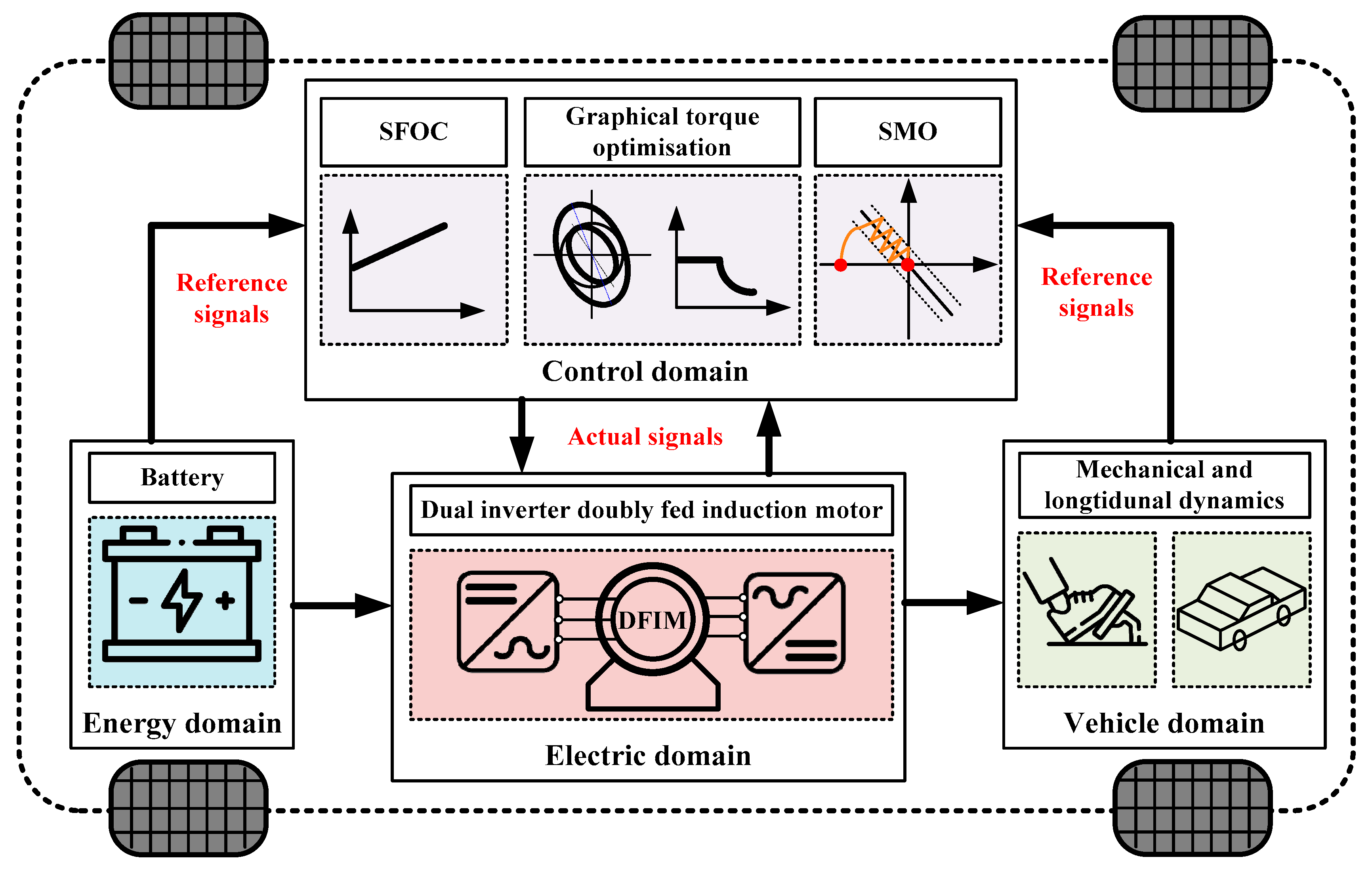
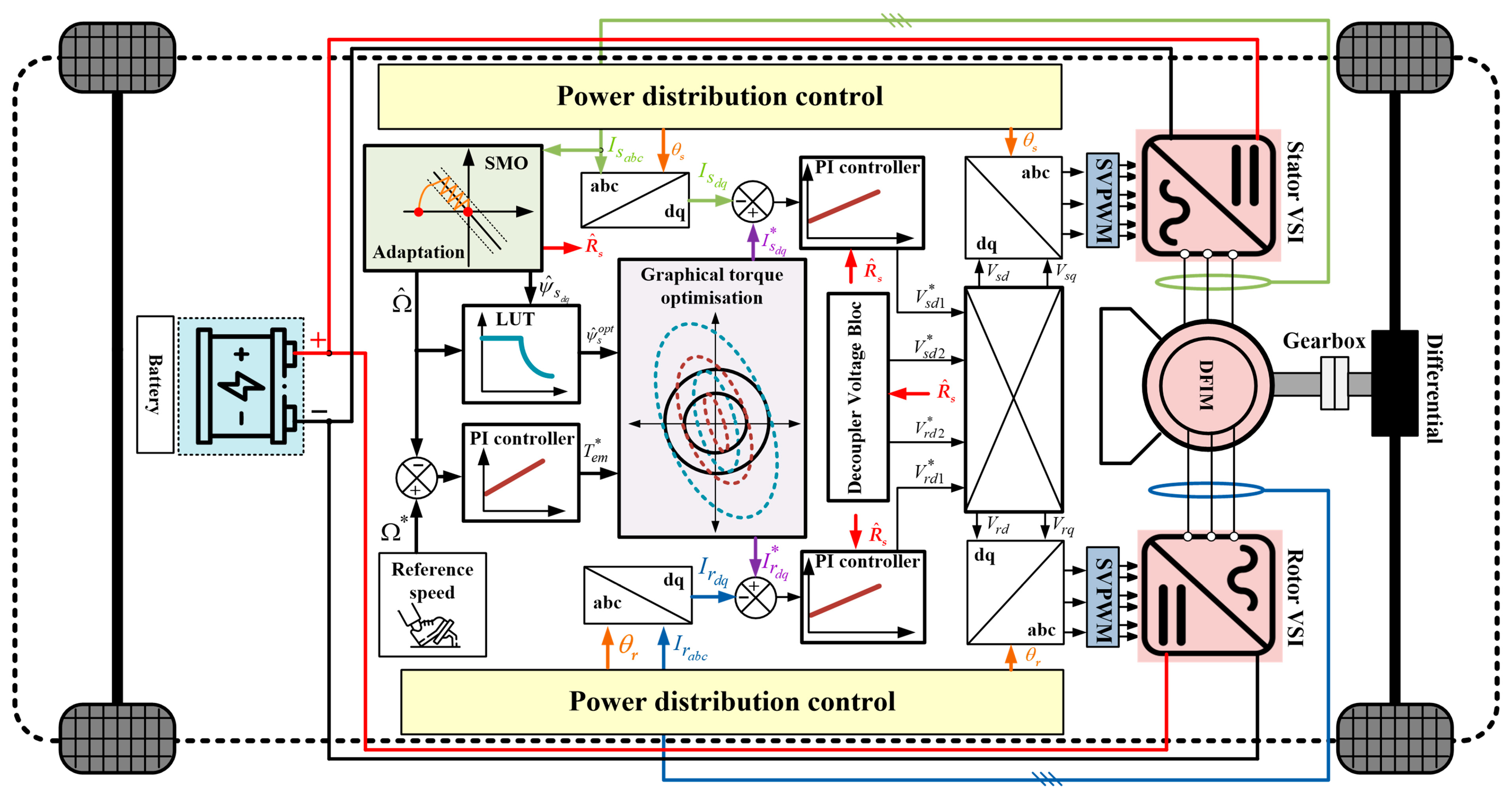
The battery supplies both inverters through a common DC link capacitor, enabling bidirectional energy exchange during motoring and regenerative braking. The block diagram of the proposed EV traction system is illustrated in Figure 1. The complete propulsion system comprises four closely coupled subsystems: the electrical domain, the control domain, the energy domain, and the mechanical/vehicle domain.
2.1. Electric Domain
2.1.1. Traction Motor Model
A rigorous mathematical model is required to support the design of observers, the development of vector controls, and stability analysis. In this study, the DFIM is represented in a synchronously rotating reference frame. The stator and rotor electrical equations are formulated using the complex representation as in the following system:
where and are the stator and rotor resistances, and denote stator and rotor electrical angular velocities, and is Laplace operator. , and represent the voltages, the flux linkages and currents, respectively. The complex form of the flux linkages is expressed using the standard induction machine magnetizing model, which includes both self- and mutual-inductance terms:
where and represent the stator and rotor self-inductances, respectively, and is the mutual inductance.
Figure 1.
Block diagram of the proposed EV traction system based on dual inverter DFIM.
2.1.2. VSI and SVPWM Modeling
Both the stator- and rotor-side converters are modeled as ideal two-level VSIs. Each inverter consists of six IGBT switches equipped with antiparallel diodes and driven by the SVPWM technique. In the SVPWM theory, the three-phase switching states are represented by a single complex voltage vector. The resulting reference vector for either the stator or rotor inverter is expressed as
where is the DC bus voltage and are the switching logic states. The SVPWM algorithm synthesizes the desired reference vector by selecting the appropriate switching combination among the eight possible voltage vectors. Six of these vectors are active, while two correspond to the zero-voltage vectors. These vectors are given by
To generate the reference vector , the SVPWM algorithm identifies the sector of the voltage space vector plane and computes the adjacent active vector application times. These times, denoted and , are given by
where is the instantaneous angle of the stator or rotor reference vector and is the sampling period. Therefore, the proportion of time during which the inverter applies each of the three voltage vectors within a switching period is defined by the corresponding duty cycles. These duty cycles are obtained by normalizing the computed switching intervals with respect to the sampling period such as
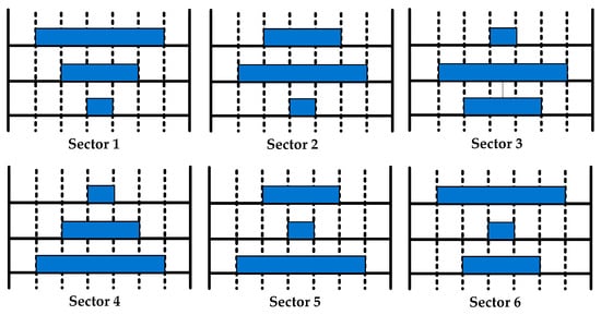
The resulting switching sequence for all operating sectors is typically symmetrized to minimize harmonic distortion, as shown in Figure 2.
Figure 2.
Switching sequence distribution for all sectors.
2.2. Vehicle Domain
2.2.1. Vehicle Load Torque Generation
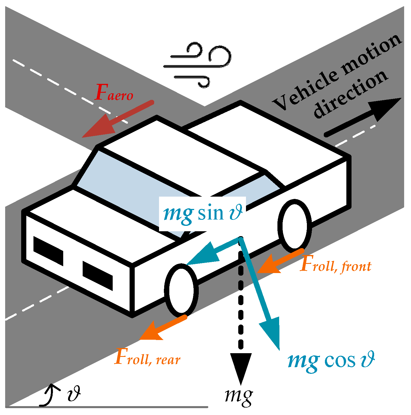
In traction operation, the longitudinal behavior of a vehicle arises from the interaction between gravity, rolling resistance, aerodynamic drag, and the inertial demand associated with speed transients. The longitudinal force is transmitted through the wheel–drivetrain assembly and translated into a mechanical load torque acting on the electric machine. Considering a fixed gear ratio and a wheel radius , the load torque applied to the motor shaft is obtained from the longitudinal road-load forces as
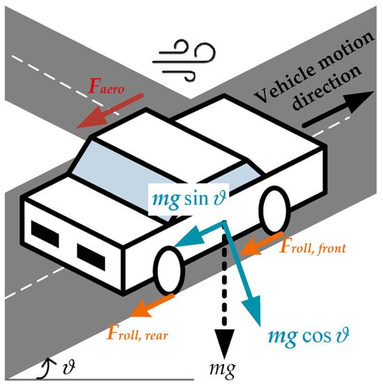
where denotes the aerodynamic drag force, represents the rolling resistance force, and accounts for road slope effects. For the WLTC driving cycle considered in this study, a flat road is assumed, leading to . Figure 3 illustrates the longitudinal forces acting on the vehicle during traction. The aerodynamic drag and rolling resistance forces at both the front and rear wheels oppose the direction of motion and collectively contribute to the load torque . On an inclined road, the gravitational force acts through its longitudinal component .
Figure 3.
Longitudinal forces acting on the vehicle during traction operation, including aerodynamic drag, rolling resistance forces at the front and rear wheels, and gravitational force components.
For operation on a horizontal road segment and under negligible wind disturbance, the load torque simplifies to a quadratic function of the motor speed, as expressed by the following equation:
where denotes the mechanical motor speed. The coefficients and are constants that depend on the vehicle parameters. The detailed derivation used to obtain these coefficients are provided in Appendix A.1.
2.2.2. Mechanical and Electromechanical Dynamics
The mechanical coupling between the traction motor and the driving wheels is established by the gear set, which converts motor torque and speed to the corresponding wheel quantities while accounting for mechanical losses. The rotational dynamics of DFIM can therefore be expressed as
denotes the total inertia referred to the motor shaft, is the viscous friction coefficient, and is the electromagnetic torque generated by the DFIM obtained from the axis flux and current components as
2.3. Energy Domain
The energy source is a lithium-ion battery pack modeled using the standard Thevenin representation:
where is the open-circuit voltage, is the internal resistance, and is the battery current. The DC link voltage dynamics are
with as the DC link capacitance, and and as the DC currents drawn by the stator and rotor VSIs.
3. Control Structure Overview and Proposed Control Strategy
The proposed control strategy is designed to achieve high-performance, sensorless traction control of the DFIM across the entire operating range of an electric vehicle. The architecture comprises four parts: (i) a SFOC strategy that independently regulates torque and flux by aligning the synchronous reference frame with the stator flux vector, (ii) a power distribution law ensuring optimal stator–rotor power sharing across sub- and super-synchronous regions, (iii) a graphical torque optimization method that enforces inverter and machine constraints while maximizing torque generation, and (iv) a sliding-mode observer that reconstructs stator flux and speed in real time. All components are embedded in a centralized control unit interfaced with the stator- and rotor-side VSIs.
A schematic overview of the control structure is presented in Figure 4.
Figure 4.
Block diagram of the proposed sensorless control architecture.
3.1. Region I
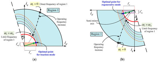
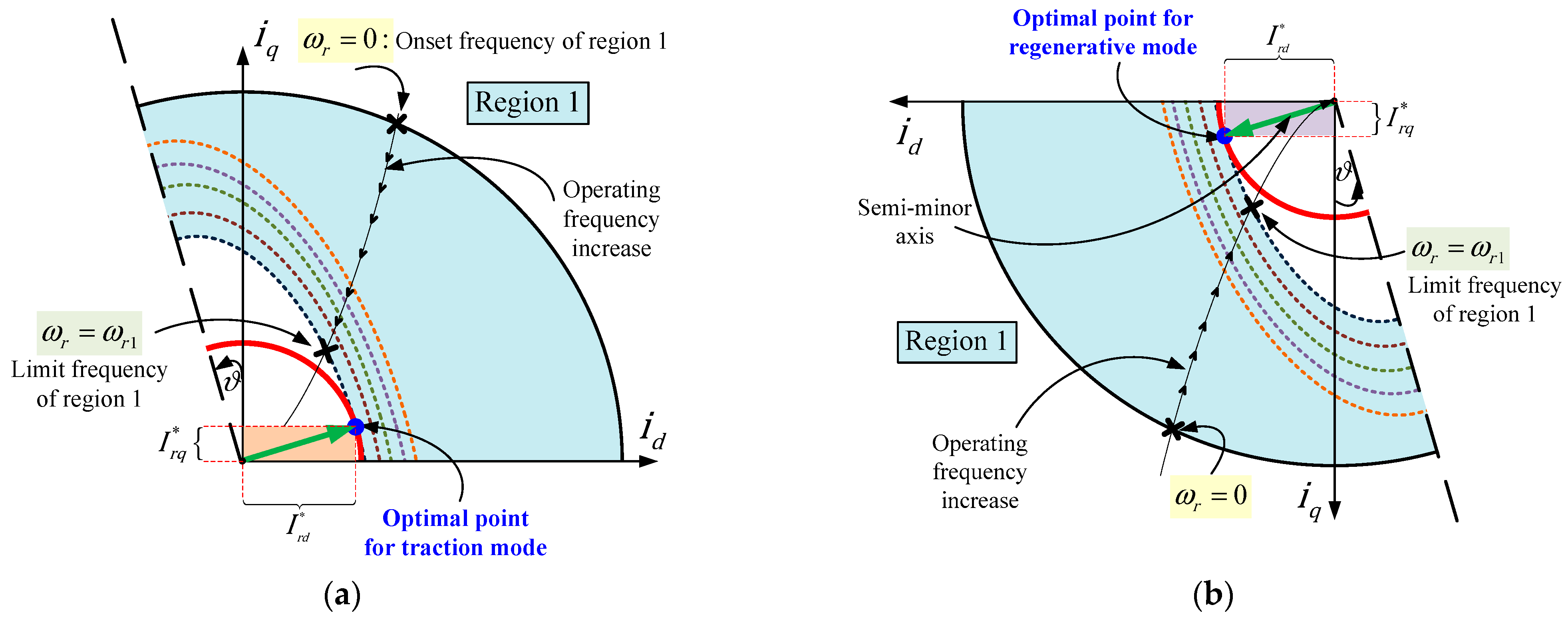
In this region, the motor operates in constant flux mode, where the rotor electrical angular velocity varies from zero up to its respective threshold . In this operating zone, the voltage applied to the motor remains sufficiently lower than the maximum output of the inverters. As a result, the voltage ellipse (blue dashed line) fully encloses its corresponding current limit circle (red). In particular, the half-minor axis of the voltage ellipse exceeds the radius of the current circle. This ensures that the controller can inject the desired current vector (green) without violating voltage or current limits, allowing full torque capability within the entire frame. Two admissible current reference vectors are defined, the first associated with the traction operating mode (Figure 5a) and the second with regenerative (Figure 5b).
Figure 5.
Graphical representation of the desired current vector in constant torque region. (a) Desired vector current during traction mode. (b) Desired vector current during regenerative mode.
3.2. Region II
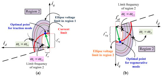
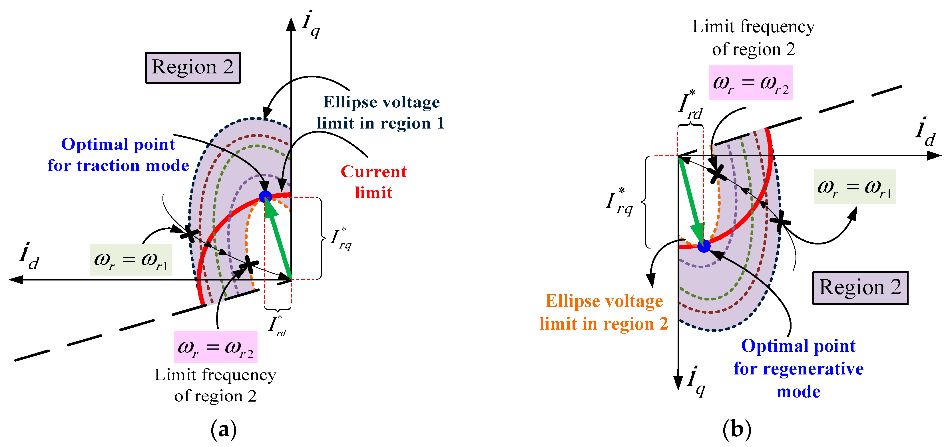
As the motor speed increases, it enters the field weakening region. This transition occurs when the angular velocity exceeds , causing the back-EMF to approach the maximum inverter voltage. Consequently, the flux reference must be reduced to maintain the voltage magnitude within the inverter capabilities. As shown in Figure 6, the reduced voltage ellipse in this region is highlighted with orange dashes. In this region, only a portion of the current circle lies within the voltage ellipse. Therefore, the controller must compute a reduced flux reference such that the optimal current vector lies at the intersection of the voltage ellipse and the current circle. The optimal current reference is represented by the green vector, shown in Figure 6a for traction operation and in Figure 6b for regenerative braking.
Figure 6.
Graphical representation of the desired current vector in field weakening region. (a) Desired vector current during traction mode. (b) Desired vector current during regenerative mode.
3.3. Control Algorithm
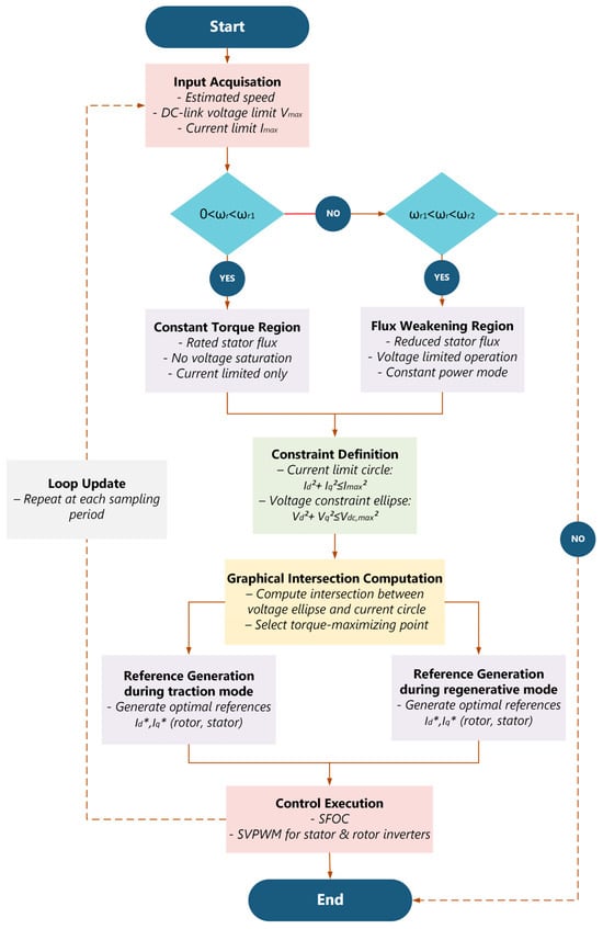
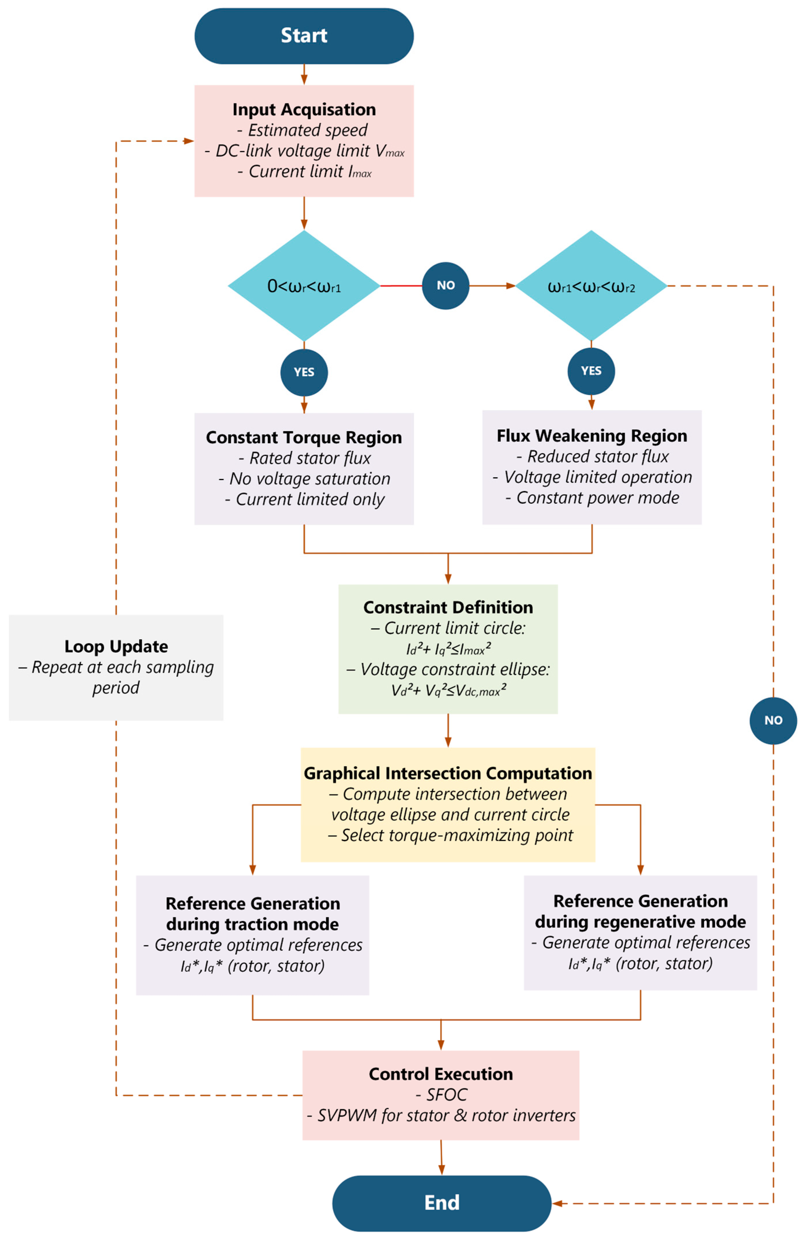
For practical implementation of the graphical torque optimization strategy, the computational sequence u in this study is summarized by the flowchart shown in Figure 7, while detailed mathematical derivations are available in [9].
Figure 7.
Flowchart of the graphical flux–torque optimization algorithm used to determine optimal current references under voltage and current constraints across constant-torque and flux-weakening operating regions.
As illustrated in Figure 7, the algorithm operates by first identifying the operating region based on the estimated rotor speed, then constructing the admissible voltage ellipses and current limit circles imposed by the dual-inverter constraints. In the constant-flux region, the rated flux reference is directly applied, whereas in the flux-weakening region, the optimal operating point is determined at the intersection of the voltage and current boundaries, ensuring maximum torque production under constrained conditions. The resulting optimal current references are subsequently supplied to the stator-flux-oriented control and SVPWM blocks. This method relies on simple algebraic evaluations and region selection logic, without iterative numerical optimization, making it suitable for real-time implementation in embedded EV traction controllers.
3.4. Proposed SMO for Sensorless Control
Accurate rotor speed and flux estimation is essential for achieving high-performance control in sensorless DFIM traction systems, particularly under low-speed operation, flux-weakening conditions, and bidirectional power flow.
3.4.1. SMO Formulation
In this work, a sliding-mode observer is formulated in the synchronous frame to estimate the stator flux vector and the mechanical speed . The observer structure is derived directly from the DFIM state equations, in which the electrical dynamics can be expressed as
where is the dispersion coefficient, is the estimated speed, is the estimated vector composed of the stator flux and current, and is the input control vector. and are, respectively, the flux and current SMO gain matrices formulated as follows:
where are the observation gains.
is the sliding surface expressed in the following manner:
with
and are the observation error for stator flux and current given by
To determine the observation gains, let us define the derivative of the observation error:
Given that the stator currents are directly measured on the test bench through high-resolution digital acquisition, their accurate reconstruction within the observer model inherently drives the associated current estimation error toward zero. Under these conditions, the observer’s current gain matrix can be expressed in the reduced form as in (19), ensuring that only the flux- and speed-related components require corrective action.
and are two positive constants determined by enforcing the stability conditions established according to the Lyapunov-based approach.
To derive the flux correction gain, the analysis assumes that the system trajectories have reached the sliding manifold . Under this condition, the evolution of the flux estimation error in sliding mode can be characterized explicitly. According to (18), enforcing and implies the cancelation of both the current estimation error and its time derivative , which leads to the following expression:
From (20), the sign vector can be computed as
Substituting (21) into the error equations of the fluxes in (18) we find
Since the observer is structured to enforce an exponential convergence of the flux estimation error, its dynamics can be prescribed as
where and are strictly positive scalars ensuring asymptotic convergence. By matching this imposed behavior (23) with the observer dynamics (22), the observer’s curflux gain matrix can be obtained by direct identification:
3.4.2. Lyapunov-Based Stability Analysis
To guarantee the robustness of the proposed sliding-mode observer, the analysis must demonstrate that the estimation error trajectories ultimately converge toward the prescribed sliding manifold. This requirement is assessed using a Lyapunov approach. Let the Lyapunov candidate be defined as
Ensuring asymptotic stability requires that the derivative of along the observer trajectories satisfies . By substituting the expression of and its time derivative into , we find
or even
Hence,
The resulting inequality reveals that the sign-switching gains must dominate the residual flux error terms. More specifically, after algebraic manipulation, the stability condition reduces to the requirement that:
Considering the estimation errors in rotor resistance and mechanical speed, defining by and , the model (18) is modified as follows:
Following the same Lyapunov-based analytical approach, the stability analysis is extended to explicitly account for both rotor resistance and mechanical speed estimation errors. Under these considerations, observer stability is preserved provided that the design parameters and satisfy the following conditions:
This guarantees that the observer error dynamics are driven toward the sliding surface and remain on it thereafter, thereby ensuring global convergence of the flux and speed estimates and establishing the Lyapunov stability of the complete sensorless estimation scheme.
3.4.3. Estimation of Mechanical Speed and Rotor Resistance
To ensure a sensorless control scheme and enhance the robustness of the sliding-mode observer against rotor resistance variations, an online adaptation mechanism based on Lyapunov stability theory is introduced. The estimation of the mechanical speed and rotor resistance requires compensating the disturbance terms that appear in the derivative of the Lyapunov function associated with the flux-observer dynamics:
These perturbations arise from simultaneous mismatches in the mechanical speed and rotor resistance, which appear explicitly in the Lyapunov function derivative through the terms . The first term is associated with rotor speed estimation error and reflects the coupling between electrical and mechanical dynamics, while the second term originates from rotor resistance uncertainty and directly affects the current–flux relationship. Both perturbations act as bounded disturbances in the observer error dynamics and must be compensated to preserve convergence and stability.
To compensate for these perturbation terms, a modified Lyapunov function, incorporating additional terms for mechanical speed and rotor resistance estimation errors, is introduced. This new Lyapunov function takes the following general form:
where denotes the Lyapunov function governing the flux error, and are design constants that ensures proper weighting for both mechanical speed and rotor resistance estimation.
The differentiation of along the observer trajectories reveals that the added speed and rotor resistance error terms enable explicit cancelation of the disturbance components that remained uncompensated in the pure flux-based formulation.
To preserve the negative definiteness of the Lyapunov function derivative , adaptive laws for rotor speed and rotor resistance are derived.
This guarantees a stable and accurate reconstruction of both the mechanical speed and rotor resistance without requiring physical sensors, even in the presence of significant load variations and parametric uncertainties.
4. Simulation Results and Discussion
To validate the effectiveness of the proposed sensorless control strategy, comprehensive simulations were carried out in MATLAB/Simulink using a detailed model of the DFIM traction system, including inverter switching dynamics, battery-fed DC links, and the complete vehicle longitudinal model. All simulations were performed under the WLTC-Class 3 driving cycle, which provides representative speed and load variations for electric vehicle applications. The parameters of the vehicle and the DFIM used in simulation are given, respectively, in Appendix A.1 and Appendix A.2. The performance of the SFOC, SMO, graphical torque optimization, and power-sharing mechanisms was evaluated across both sub-synchronous and super-synchronous operating regions.
4.1. Dynamic Response of the SMO-Based DFIM Traction Drive
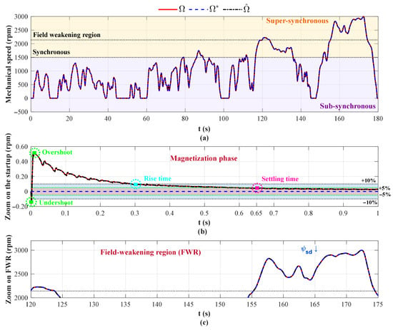
Figure 8 illustrates accurate tracking of the reference trajectory throughout the full 180 s scenario, covering sub-synchronous, synchronous, and super-synchronous operating regions.
Figure 8.
Mechanical speed response under the proposed SMO-based sensorless control. (a) , , . (b) zoom during magnetization phase. (c) zoom in the field weakening region.
Figure 8a illustrates reference, measured and estimated mechanical speeds. The estimated speed closely follows the actual value with a maximum deviation below 2%, even during abrupt acceleration and deceleration phases. During the initial magnetization phase (Figure 8b), short rise times (=0.3 s) and negligible transient speed overshoot are observed; these phenomena are attributed to the flux establishment process and the quadratic vehicle load, respectively. During the initial acceleration and subsequent load perturbations, the closed loop remains without oscillations, and no delay in the speed estimation is perceptible. As the vehicle transitions through low-, medium-, high-, and very-high-speed regions (Figure 8c), including operation in the super-synchronous mode, the proposed SMO preserves accurate and stable speed estimation despite the significant increase in back-EMF and inverter switching nonlinearities. This operating regime is particularly challenging for sensorless control, as it involves reduced voltage margins and strong coupling between electromagnetic torque, flux, and speed dynamics. In the dual-inverter DFIM architecture, super-synchronous operation further implies active power exchange between the stator-side and rotor-side converters, requiring precise flux and speed information to ensure balanced power sharing and stable operation of both inverters. The ability of the SMO to maintain reliable estimation under these conditions demonstrates its suitability for coordinated stator–rotor power management. Moreover, stable sensorless operation in the super-synchronous region enables an extended constant-power speed range and efficient energy flow through the rotor circuit, which is essential for high-speed traction and regenerative braking in electric vehicle applications. The obtained results confirm that the proposed SMO-based control strategy effectively supports the intrinsic advantages of the bi-inverter DFIM topology while preserving robustness under demanding high-speed operating conditions.
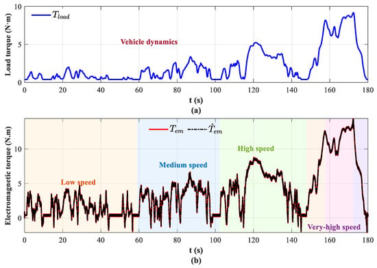
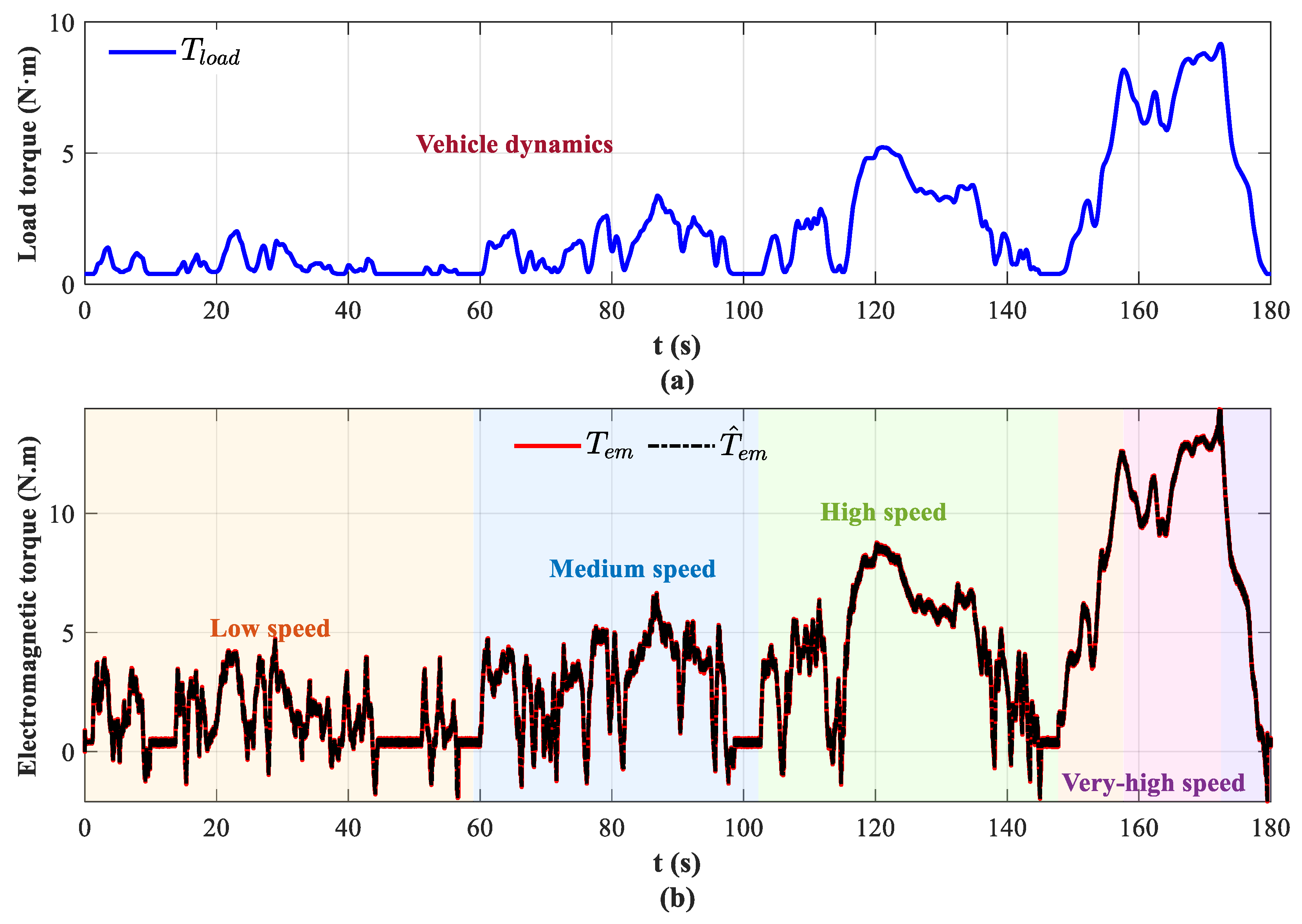
The electromagnetic torque evolution of the traction system is depicted in Figure 9. Figure 9a presents the quadratic vehicle load response which depends on the longitudinal dynamics of the vehicle. The electromagnetic torque response, shown in Figure 9b, closely follows its estimate with minimal ripple, confirming the estimator’s ability to track rapid variations in load conditions. The torque transitions between sub-synchronous and super-synchronous modes are smooth and free of discontinuities, confirming the effectiveness of the proposed power-sharing strategy. Moreover, the graphical torque-optimization algorithm effectively maintains the operating point within the permissible voltage region, especially at high speeds where flux weakening becomes dominant. This ensures that the control architecture preserves observability at high speeds, where classical observers frequently lose accuracy.
Figure 9.
Electromagnetic torque evolution during the drive cycle. (a) Load torque . (b) and .
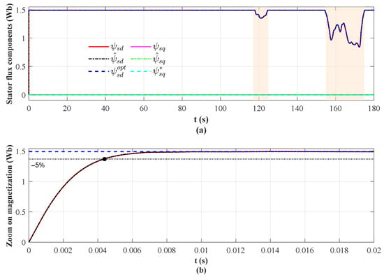
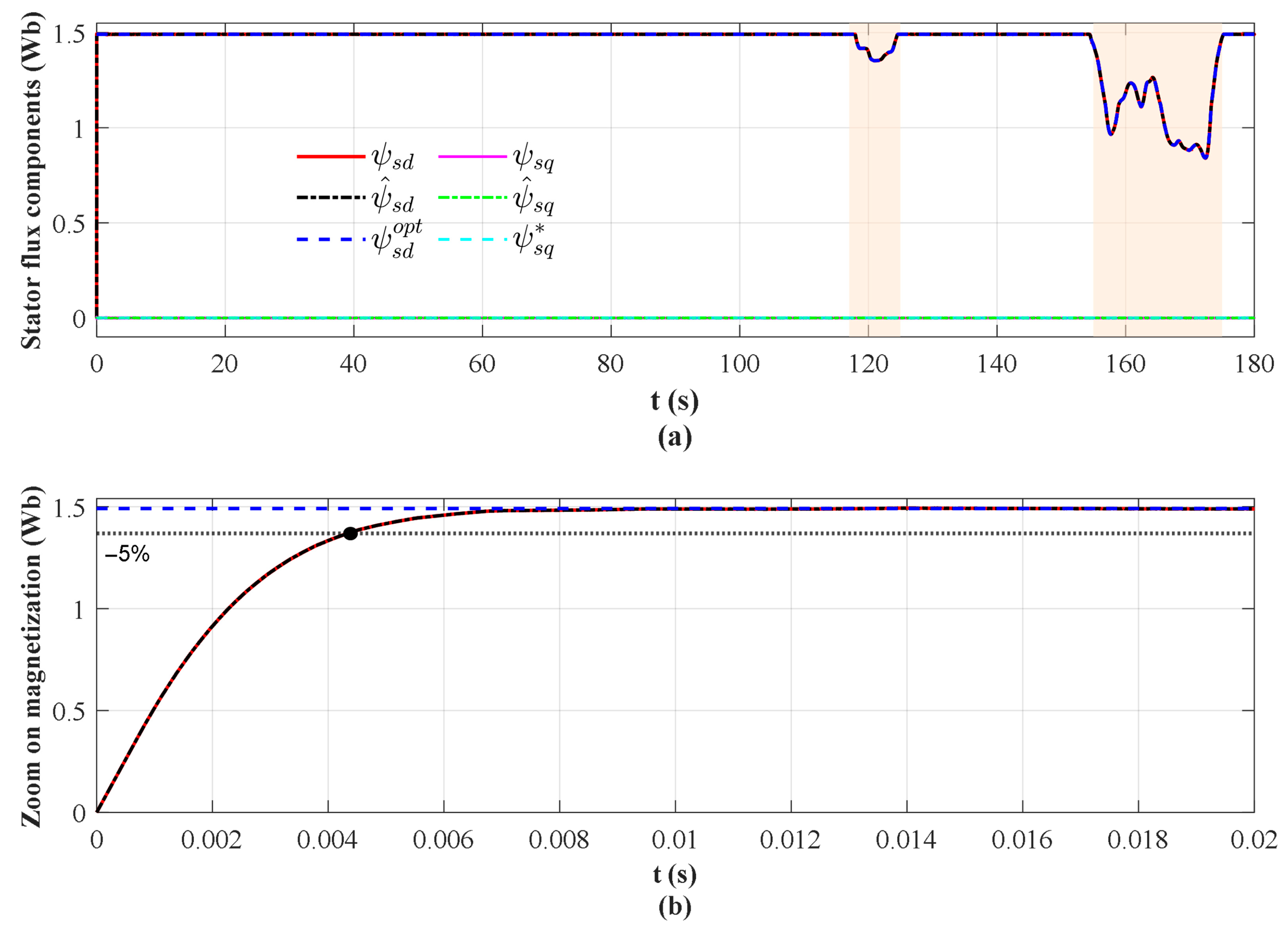
A key contribution of the proposed approach lies in the accurate reconstruction of the stator flux linkage. Figure 10a presents the actual, estimated, and reference stator flux components in the frame. The SMO maintains excellent flux-tracking accuracy at both low and high speeds, including regions where classical observers typically suffer from degraded observability. The sliding correction term effectively eliminates disturbances associated with load variations and inverter nonlinearities. Figure 10b presents the flux estimation convergence during the magnetization phase. As observed, the stator flux trajectory converges rapidly during the magnetization phase, exhibiting a critically damped profile characterized by a short rise time, very small overshoot, and a settling time well below 45 ms. Such behavior is essential in traction applications, as it guarantees that torque production is immediately available for vehicle launch or recovery after braking.
Figure 10.
Stator flux behavior under the proposed sensorless control strategy. (a) Estimated and reference flux components in the frame: , , , , , and . (b) Flux estimation convergence during the magnetization phase.
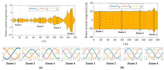
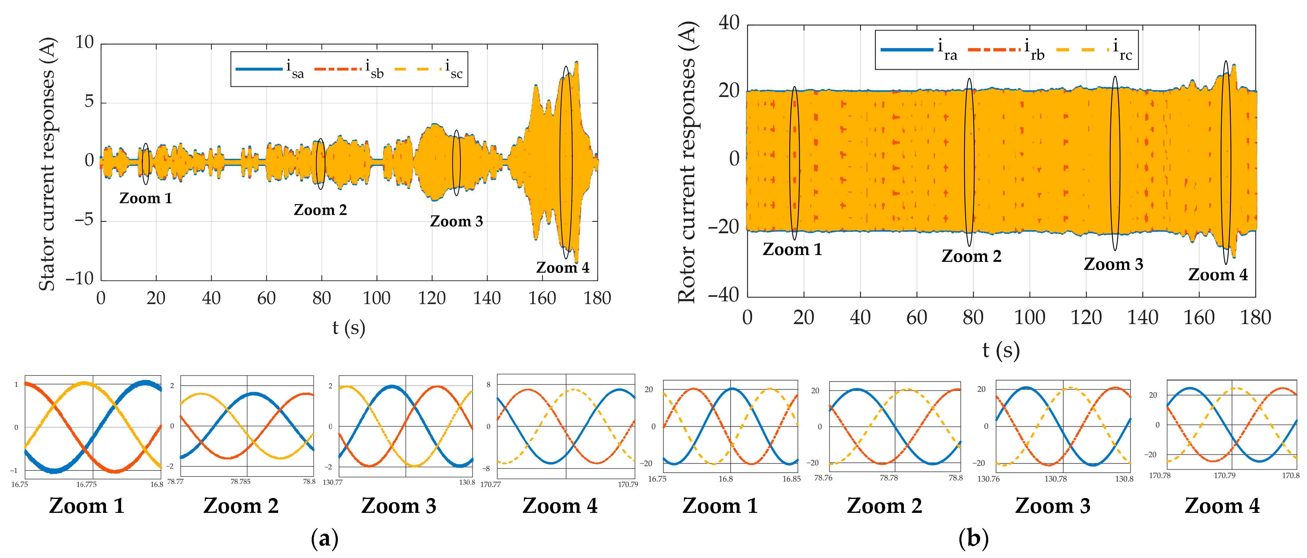
Figure 11a,b illustrate the stator and rotor phase-current waveforms generated by the dual-inverter DFIM drive during the WLTC cycle, with additional zoomed-in views provided for representative low-, medium-, high-, and very-high-speed operating regions to highlight waveform quality and distortion levels. Despite the strong variations in mechanical load and the wide speed range, the measured currents remain well-balanced, quasi-sinusoidal, and free from low-frequency distortion. The zoomed waveforms confirm a consistent phase symmetry and the minimal harmonic content, demonstrating that the proposed SFOC–SMO control loop maintains stable current dynamics even under rapid torque and speed transitions.
Figure 11.
Time-domain stator and rotor current responses of the dual-inverter-fed DFIM under the WLTC driving cycle with zoomed views corresponding to low, medium-, high-, and very-high-speed operating regions. (a) Stator phase currents , , and . (b) Rotor phase currents , , and .
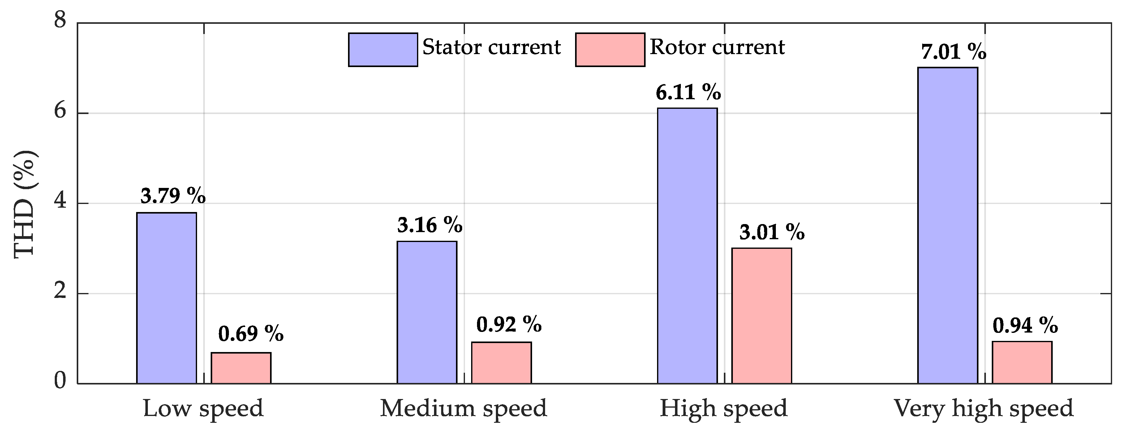
The quantitative assessment of both stator and rotor current quality at low, medium, high, and very high speeds is provided by the THD analysis in Figure 12. Rotor current THD remains consistently low across all operating points (≈0.7–0.9%), indicating effective harmonic containment on the rotor side. Conversely, stator current THD increases with speed, reaching a maximum of 7.01% in deep field-weakening operation. This behavior is intrinsic to voltage-limited traction drives, where reduced voltage margin and increased modulation index enhance harmonic distortion. From an automotive traction perspective, stator current THD levels below 8% are generally regarded as acceptable during high-speed field-weakening operation, as commonly reported in IEC-oriented traction studies and industrial drive practice. Recent works on induction and DFIM drives operating in field-weakening regions under predictive and six-step control report THD values in the range of 8–15% [38,39,40]. Compared to these works, the proposed dual-inverter DFIM drive achieves reduced harmonic distortion while preserving extended speed capability. The observed THD level is expected to induce only limited torque ripple and marginal additional inverter losses, with negligible impact on NVH performance due to drivetrain inertia and electromagnetic filtering. Consequently, the reported harmonic levels remain compatible with high-performance EV traction requirements, particularly when considering the benefits of extended speed operation and the excellent harmonic cleanliness maintained in the rotor circuit.
Figure 12.
Total harmonic distortion (THD) levels for both stator and rotor currents at four representative operating points.
4.2. Performance Assessment of the Proposed Sensorless Controller
4.2.1. Phase Portrait Analysis
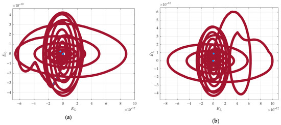
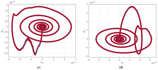
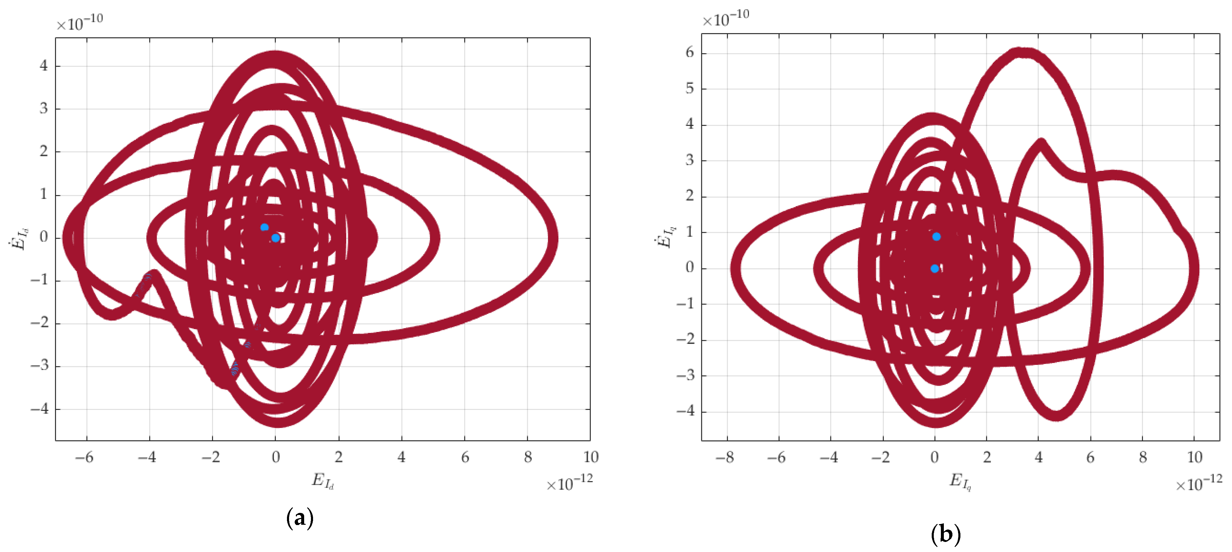
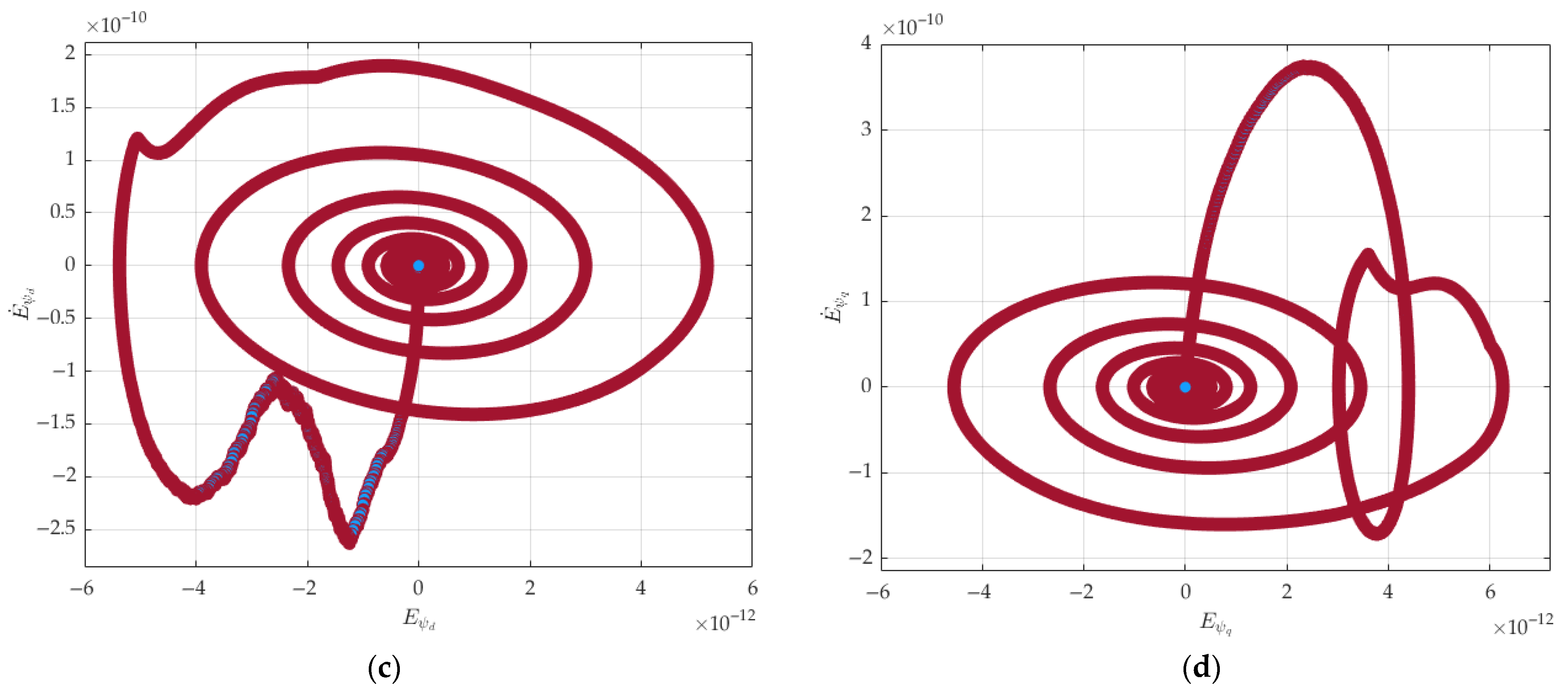
To rigorously evaluate the robustness and stability characteristics of the proposed sliding-mode-based sensorless controller, the dynamic behavior of the estimation errors was analyzed through phase portrait representations. Figure 13 summarizes the trajectories of the current and stator flux estimation errors and their time derivatives while the machine is driven under WLTC drive cycle.
Figure 13.
Phase portraits of the estimation errors under WLTC cycle drive: (a) vs. ; (b) vs. ; (c) vs. ; (d) vs. .
The portraits in Figure 13a,b, depicting vs. and vs. , respectively, exhibit the characteristic signatures of a stable sliding-mode dynamics. In both subfigures, the trajectories converge monotonically toward the origin, following inward-spiraling paths that gradually contract as the estimation error diminishes. This dynamical response indicates that the designed switching gains are appropriately chosen to compensate for model uncertainties and external perturbations, leading to finite-time convergence of the current estimation error.
The flux error phase portraits presented in Figure 13c,d, further validate the robustness of the proposed observer structure. The observed trajectories show wide initial orbits, followed by a consistent inward spiral. This behavior confirms that the flux reconstruction benefits from the stability provided by the current’s sliding motion. Once the observer reaches the sliding manifold, the equivalent dynamics guarantee that the flux error decreases asymptotically despite the presence of abrupt torque transitions and voltage ripples in the WLTC cycle.
The final regions highlighted in blue across all subfigures confirm that the steady-state estimation error remains negligible even under severe excitation. The four phase portraits demonstrate that the proposed sensorless control architecture achieves robust, convergent, and structurally stable estimation dynamics.
4.2.2. Evaluation Under Low Speed and Rotor Resistance Variation
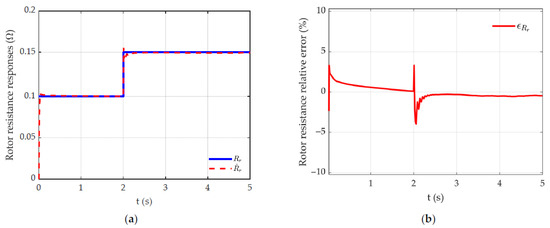
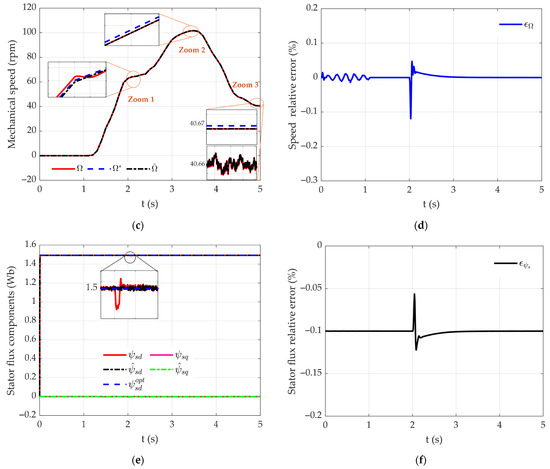
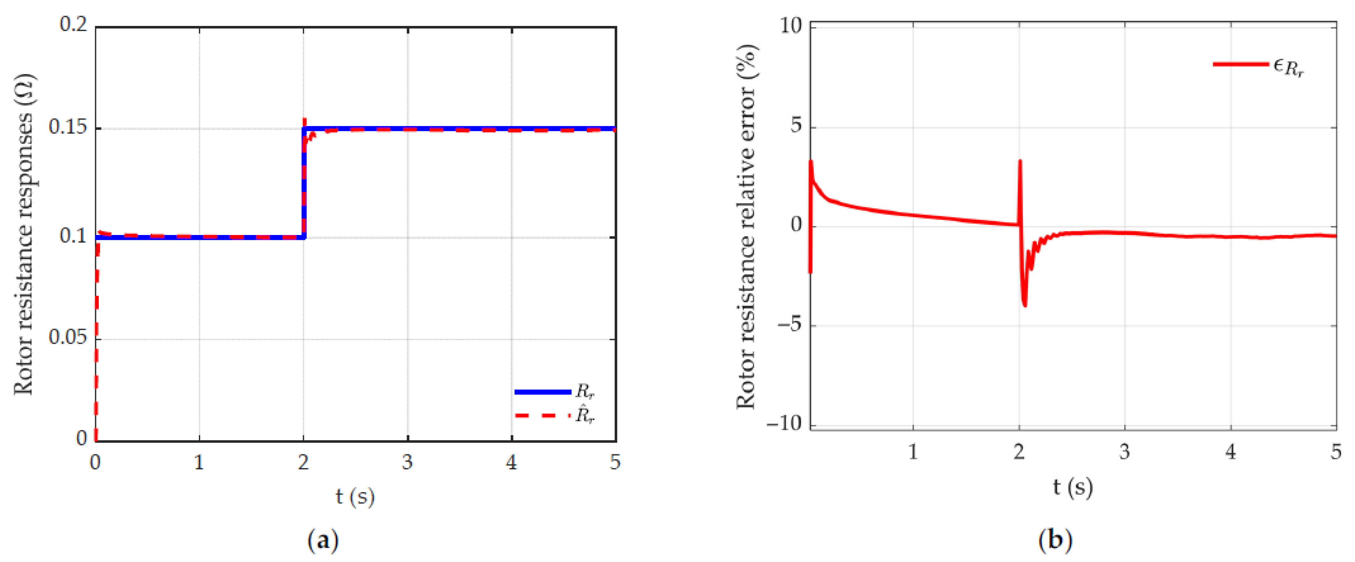
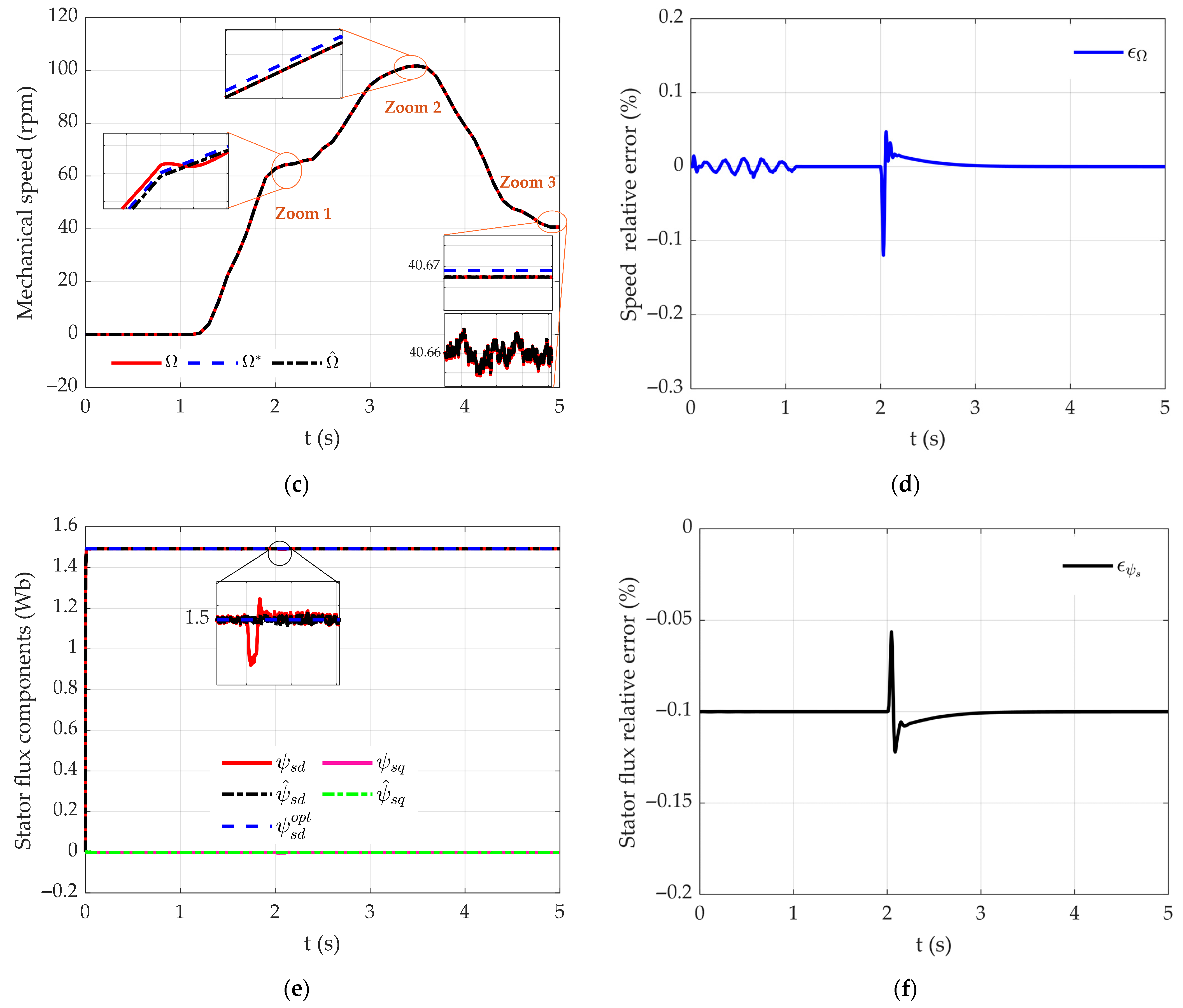
To assess the robustness of the proposed SMO at low speed and parameter uncertainties, a near-zero-speed operating scenario (<100 rpm) combined with a sudden rotor resistance variation of 50% (at t = 2 s) is investigated. The evaluation criterion adopted in this study is based on the relative estimation error between the measured and estimated quantities, formulated as follows:
Figure 14a shows the evolution of real and estimated rotor resistance. Without online adaptation, such a parametric deviation leads to divergence between the real and estimated states. By contrast, the proposed Lyapunov-based adaptation mechanism ensures fast and stable convergence of the estimated resistance toward its true value, as confirmed by the bounded estimation error in Figure 14b. The impact of this adaptation on speed estimation performance is illustrated in Figure 14c. Despite the weak observability inherent to low-speed operation, the estimated mechanical speed remains perfectly superimposed on the real speed, including during the transient resistance. The corresponding relative speed estimation error, shown in Figure 14d, exhibits only a short-duration peak before rapidly converging to zero, indicating preserved observer stability and estimation accuracy under conditions that are representative of practical disturbances, including those caused by inverter dead time and noisy current measurements. Similar behavior is observed for the stator flux components in Figure 14e, with the relative flux error in Figure 14f remaining negligible. These results demonstrate that the proposed SMO, combined with Lyapunov-based rotor resistance adaptation, maintains accurate speed and flux estimation under low-speed operation and severe parameter variations, thereby reinforcing its suitability for robust sensorless DFIM traction control.
Figure 14.
Performance of the proposed sliding-mode observer with Lyapunov-based rotor resistance adaptation under low-speed operation and parameter variation: (a) Real and estimated rotor resistance following a sudden 50% variation. (b) Relative rotor resistance estimation error. (c) Real, estimated, and reference mechanical speeds with zoomed views in the low-speed region. (d) Relative speed estimation error. (e) Real and estimated stator flux components with transient zoom. (f) Relative stator flux estimation error.
4.2.3. Performance Analysis Summary
The robustness and accuracy of the controller–observer were also evaluated through the key metrics commonly employed in recent DFIM traction studies, including dynamic quality indices, steady-state errors, harmonic performance, and stability proof. Table 1 summarizes the main performance indices of the DFIM traction drive under the proposed sensorless control strategy.
Table 1.
Performance summary of the proposed SMO-based DFIM traction controller.
5. Conclusions
This study has presented a high-performance sensorless control architecture for dual-inverter doubly fed induction motors intended for electric vehicle traction. A sliding-mode observer has been rigorously integrated within a stator-flux-oriented control strategy to enable reliable reconstruction of the stator flux and mechanical speed over the entire operating range, including deep field-weakening. The dual-inverter topology, combined with the proposed torque-optimization strategy, ensures efficient distribution of active power between the stator and rotor sides while limiting current stress during transient and high-load conditions.
Simulation results obtained under the full WLTC driving profile confirm the effectiveness of the proposed approach. The observer exhibits rapid convergence and strong robustness against load disturbances, parameter uncertainties, and inverter switching ripple. The SMO-based speed estimation remains stable even when the back-EMF amplitude becomes critically low, thereby preserving observability in both low-speed and very-high-speed regions. Furthermore, the coordinated control of the two inverters achieves smooth torque production, reduced energy-consumption peaks, and operation within safe thermal and electrical margins. These results demonstrate that the proposed DFIM-based drive, supported by advanced sensorless control, is well suited for next-generation electric-vehicle propulsion systems where efficiency, durability, and reliability are paramount.
Future investigations will extend this work in several directions. First, experimental validation on a full-scale dual-inverter DFIM test bench will be undertaken to assess observer dynamics under real switching nonlinearities, inverter dead times, and measurement noise. Second, adaptive or data-driven tuning of the SMO gains will be explored to further mitigate the influence of parameter drift, particularly in high-temperature automotive environments.
Author Contributions
Conceptualization, M.Z.; methodology, M.Z.; software, M.Z.; validation, M.Z. and A.K.; investigation, M.Z.; writing—original draft preparation, M.Z.; writing—review and editing, A.K.; visualization, M.Z. and A.K.; supervision, A.K. All authors have read and agreed to the published version of the manuscript.
Funding
This research received no external funding.
Data Availability Statement
The original contributions presented in this study are included in the article.
Conflicts of Interest
The authors declare no conflicts of interest.
Appendix A
Appendix A.1
The constants and are dimensional coefficients derived from the vehicle and drivetrain parameters, and their expressions are given as follows:
The coefficient is associated with the aerodynamic drag contribution and has units of Nm (s/m)2, while represents the rolling and gravitational load contribution and is expressed in . The specifications and coefficients of the selected EV are shown in Table A1.
Table A1.
Vehicle parameters used in simulation.
Appendix A.2
In this study, a 4 kW bipolar DFIM was used, and its parameters are summarized in Table A2.
Table A2.
Doubly fed induction machine parameters used in simulation.
References
- IEA: Global EV Outlook. 2025. Available online: https://www.iea.org/reports/global-ev-outlook-2025 (accessed on 19 November 2025).
- Abad, G. Power Electronics and Electric Drives for Traction Applications; Wiley: New York, NY, USA, 2017; p. 630. [Google Scholar]
- Husain, I.; Ozpineci, B.; Islam, M.S.; Gurpinar, E.; Su, G.J.; Yu, W.; Chowdhury, S.; Xue, L.; Rahman, D.; Sahu, R. Electric drive technology trends, challenges, and opportunities for future electric vehicles. Proc. IEEE 2021, 109, 1039–1059. [Google Scholar] [CrossRef] [Scilit]
- Rinaldi, A.; Mimmi, G.; Castelli-Dezza, F.; Ferraris, M. A Comprehensive Review on Electric Traction Motor Drives for Hybrid and Electric Vehicles. IEEE Trans. Ind. Appl. 2021, 57, 1343–1357. [Google Scholar]
- Guo, S.; Zhao, H.; Wang, Y.; Yin, X.; Qi, H.; Li, P.; Lin, Z. A design technique of traction motor for efficiency improvement based on multiobjective optimization. World Electr. Veh. J. 2021, 12, 260. [Google Scholar] [CrossRef] [Scilit]
- Liu, S.M.; Tu, C.H.; Lin, C.L.; Liu, V.T. Field-oriented driving/braking control for electric vehicles. Electronics 2020, 9, 1484. [Google Scholar] [CrossRef] [Scilit]
- Chantoufi, A.; Derouich, A.; El Ouanjli, N.; Mahfoud, S.; El Idrissi, A. Improved direct torque control of doubly fed induction motor in electric vehicles using fuzzy logic controllers. e-Prime-Adv. Electr. Eng. Electron. Energy 2025, 11, 100882. [Google Scholar] [CrossRef] [Scilit]
- Han, P.; Cheng, M.; Chen, Z. Dual-electrical-port control of cascaded doubly-fed induction machine for EV/HEV applications. IEEE Trans. Ind. Appl. 2016, 53, 1390–1398. [Google Scholar] [CrossRef]
- Zerzeri, M.; Khedher, A. Optimal speed–torque control of doubly-fed induction motors: Analytical and graphical analysis. Comput. Electr. Eng. 2021, 93, 107258. [Google Scholar] [CrossRef] [Scilit]
- Zerzeri, M.; Khedher, A. A sensorless mixed DFIM control strategy based on fuzzy-PI speed controller and current sliding mode controller for electric vehicles. Int. J. Model. Identif. Control 2021, 38, 271–281. [Google Scholar] [CrossRef] [Scilit]
- Hesar, H.M.; Zarchi, H.A.; Markadeh, G.A.; Khazaee, A. Maximum torque per total ampere strategy for vector-controlled brushless doubly fed induction machine drive taking iron loss into account. IEEE Trans. Power Electron. 2022, 37, 13598–13605. [Google Scholar] [CrossRef] [Scilit]
- Ilioudis, V.C. A study of mtpa applied to sensorless control of the synchronous reluctance machine (synrm). Automation 2025, 6, 11. [Google Scholar] [CrossRef] [Scilit]
- Elkholy, M.M.; Algendy, M.M.; El-Hay, E.A. Modern Control Techniques and Operational Challenges in Permanent Magnet Synchronous Motors: A Comprehensive Review. Automation 2025, 6, 49. [Google Scholar] [CrossRef] [Scilit]
- Tir, Z.; Orlowska-Kowalska, T.; Ahmed, H.; Houari, A. Adaptive high gain observer-based MRAS for sensorless induction motor drives. IEEE Trans. Ind. Electron. 2023, 71, 271–281. [Google Scholar] [CrossRef] [Scilit]
- Boyar, A.; Kabalci, E.; Kabalci, Y. Sensorless speed controller of an induction motor with MRAS-based model predictive control. Comput. Electr. Eng. 2024, 118, 109350. [Google Scholar] [CrossRef] [Scilit]
- Iacchetti, M.F.; Carmeli, M.S.; Castelli Dezza, F.; Perini, R. A speed sensorless control based on a MRAS applied to a double fed induction machine drive. Electr. Eng. 2010, 91, 337–345. [Google Scholar] [CrossRef] [Scilit]
- Yin, Z.; Gao, F.; Zhang, Y.; Du, C.; Li, G.; Sun, X. A review of nonlinear Kalman filter appling to sensorless control for AC motor drives. CES Trans. Electr. Mach. Syst. 2019, 3, 351–362. [Google Scholar] [CrossRef] [Scilit]
- Bouchemha, A.; Azar, A.T.; Laatra, Y.; Souaidia, C.; Dib, D. Sensor and sensorless speed control of doubly-fed induction machine. Int. J. Adv. Intell. Paradigms 2021, 19, 194–215. [Google Scholar] [CrossRef] [Scilit]
- Djellouli, Y.; Ardjoun, S.A.E.M.; Zerdali, E.; Denai, M.; Chafouk, H. The Real-Time Observation of Electric Vehicle Operating Points Using an Extended Kalman Filter. Automation 2024, 5, 613–629. [Google Scholar] [CrossRef] [Scilit]
- Xu, Z.; Zhang, J.; Cheng, M. Investigation of signal injection methods for fault detection of PMSM drives. IEEE Trans. Energy Convers. 2022, 37, 2207–2216. [Google Scholar] [CrossRef] [Scilit]
- Nguyen, C.M.; Nguyen, A.T.; Delprat, S. Neural-network-based fuzzy observer with data-driven uncertainty identification for vehicle dynamics estimation under extreme driving conditions: Theory and experimental results. IEEE Trans. Veh. Technol. 2023, 72, 8686–8696. [Google Scholar] [CrossRef] [Scilit]
- Bekhiti, B.; Hariche, K.; Roudane, M.; Kabanov, A.; Kramar, V. Learning-Driven Intelligent Passivity Control Using Nonlinear State Observers for Induction Motors. Automation 2025, 6, 45. [Google Scholar] [CrossRef] [Scilit]
- Yazhini, M.; Samidurai, R.; Shang, Y. Event-triggered synchronization of fractional-order complex-valued BAM neural networks with application to image encryption. Chaos Solitons Fractals 2026, 203, 117666. [Google Scholar] [CrossRef] [Scilit]
- Allotta, B.; D’Adamio, P.; Nocentini, L.; Paolucci, L.; Pugi, L. Next generation of smart sensorless drives for sustainable underwater vehicles. IFAC-PapersOnLine 2016, 49, 481–486. [Google Scholar] [CrossRef] [Scilit]
- Jnayah, S.; Khedher, A. Improvement of DTC Performance of Three Level Inverter Fed IM Drive with High Gain Flux Observer. In Digital Technologies and Applications, ICDTA 2022; Lecture Notes in Networks and Systems; Motahhir, S., Bossoufi, B., Eds.; Springer: Cham, Switzerland, 2022; p. 54. [Google Scholar]
- Jnayah, S.; Khedher, A. Sensorless DTC-SVM applied to an induction motor controlled by a three-level inverter using SMSFO. COMPEL-Int. J. Comput. Math. Electr. Electron. Eng. 2023, 42, 1349–1371. [Google Scholar] [CrossRef] [Scilit]
- Zerzeri, M.; Moussa, I.; Khedher, A. Wind turbine emulator using three-phase IM controlled through an adaptive reactive power estimator fed by soft-VSI topology. COMPEL-Int. J. Comput. Math. Electr. Electron. Eng. 2024, 43, 282–300. [Google Scholar] [CrossRef] [Scilit]
- Moussa, I.; Zerzeri, M.; Khedher, A. Robust WTE sensorless design based on soft-VSI structure for three-phase IM drive using sliding mode observer controller. In Proceedings of the 2022 IEEE International Conference on Electrical Sciences and Technologies in Maghreb (CISTEM), Tunis, Tunisia, 26–28 October 2022. [Google Scholar]
- Delorme, L.; Ayala, M.; Gonzalez, O.; Rodas, J.; Gregor, R.; Hernandez, J.C. Speed Sensorless Control for a Six-Phase Induction Machine Based on a Sliding Mode Observer. Machines 2025, 13, 639. [Google Scholar] [CrossRef] [Scilit]
- Morawiec, M.; Lewicki, A.; Wilczyński, F. Speed observer of induction machine based on backstepping and sliding mode for low-speed operation. Asian J. Control 2021, 23, 636–647. [Google Scholar] [CrossRef] [Scilit]
- Krishna, S.M.; Daya, J.L.F.; Padmanaban, S.; Mihet-Popa, L. Real-time analysis of a modified state observer for sensorless induction motor drive used in electric vehicle applications. Energies 2017, 10, 1077. [Google Scholar] [CrossRef] [Scilit]
- Zaky, M.S.; Metwaly, M.K.; Azazi, H.Z.; Deraz, S.A. A new adaptive SMO for speed estimation of sensorless induction motor drives at zero and very low frequencies. IEEE Trans. Ind. Electron. 2018, 65, 6901–6911. [Google Scholar] [CrossRef] [Scilit]
- Zhang, L.; Dong, Z.; Zhao, L.; Laghrouche, S. Sliding mode observer for speed sensorless linear induction motor drives. IEEE Access 2021, 9, 51202–51213. [Google Scholar] [CrossRef] [Scilit]
- Ding, H.; Zou, X.; Li, J. Sensorless control strategy of permanent magnet synchronous motor based on fuzzy sliding mode observer. IEEE Access 2022, 10, 36743–36752. [Google Scholar] [CrossRef] [Scilit]
- Mansouri, S.A.; Ahmarinejad, A.; Javadi, M.S.; Heidari, R.; Catalão, J.P. Improved double-surface sliding mode observer for flux and speed estimation of induction motors. IET Electr. Power Appl. 2020, 14, 1002–1010. [Google Scholar] [CrossRef] [Scilit]
- Lu, H.; Li, W.; Du, W.L.; Wang, Y.Q.; Yang, X.F. Improved Sliding Mode Control with an Adaptive Sliding Mode Disturbance Observer for Speed Control of Permanent Magnet Semi-direct Drive Scraper Conveyor. Int. J. Control Autom. Syst. 2025, 23, 1984–1998. [Google Scholar] [CrossRef] [Scilit]
- Zhang, X. Sensorless induction motor drive using indirect vector controller and sliding-mode observer for electric vehicles. IEEE Trans. Veh. Technol. 2013, 62, 3010–3018. [Google Scholar] [CrossRef] [Scilit]
- Wang, B.; Zhang, X.; Yu, Y.; Zhang, J.; Xu, D. Maximum torque analysis and extension in six-step mode-combined field-weakening control for induction motor drives. IEEE Trans. Ind. Electron. 2019, 66, 9129–9138. [Google Scholar] [CrossRef] [Scilit]
- Zhang, Y.; Zhang, B.; Yang, H.; Norambuena, M.; Rodriguez, J. Generalized sequential model predictive control of IM drives with field-weakening ability. IEEE Trans. Power Electron. 2018, 34, 8944–8955. [Google Scholar] [CrossRef] [Scilit]
- Zhang, Y.; Bai, Y.; Yang, H.; Zhang, B. Low switching frequency model predictive control of three-level inverter-fed IM drives with speed-sensorless and field-weakening operations. IEEE Trans. Ind. Electron. 2018, 66, 4262–4272. [Google Scholar] [CrossRef] [Scilit]

Disclaimer/Publisher’s Note: The statements, opinions and data contained in all publications are solely those of the individual author(s) and contributor(s) and not of MDPI and/or the editor(s). MDPI and/or the editor(s) disclaim responsibility for any injury to people or property resulting from any ideas, methods, instructions or products referred to in the content. |
© 2026 by the authors. Licensee MDPI, Basel, Switzerland. This article is an open access article distributed under the terms and conditions of the Creative Commons Attribution (CC BY) license.