


Abstract
Achieving adequate load capacity and ensuring ductile behavior are crucial for reinforced-concrete knee joints to prevent a complete structural collapse if an adjacent member fails. The reinforcement detailing plays a critical role in achieving these factors. In this study, the performance of a knee joint under closing moments was analyzed using innovative truss-shaped reinforcement and simplified mechanical joints, in comparison to traditional reinforcement detailing, through four large-scale specimens. The findings showed that incorporating a truss-shaped reinforcement system with the suggested detailing effectively redistributed stresses in the knee-joint area and decreased stress concentration at the bent-bar zone, thus helping to prevent premature joint failure when compared to conventional specimens. Overall, the proposed system shifted the failure mode towards a highly ductile response. Furthermore, the suggested specimen experienced significant increases in both the yield load and the ultimate load, with the yield-load boost ranging from around 29.5% to 70.5%, and the ultimate-load increase ranging from 20% to 81%. Additionally, the proposed reinforcement system exhibited notably higher displacement capacity, with increases ranging from 88% to 347%. The proposed specimen also showed a considerable enhancement in displacement ductility, with an increase of roughly 160% to 382% relative to traditional specimens. The results matched well with the created analytical models confirming the effectiveness of the proposed load-transfer system.
1. Introduction
Reinforced concrete structures often incorporate corner joints in elements like shelters, tunnels, tanks, the roofs of concrete buildings, and bridge abutment connections. These joints play a crucial role in bearing and transferring stresses among adjacent parts of the structure. Moreover, the process of retrofitting and enhancing the performance of a corner joint is a complex task. Therefore, it is essential for the joint to possess high ductility and energy dissipation capabilities.
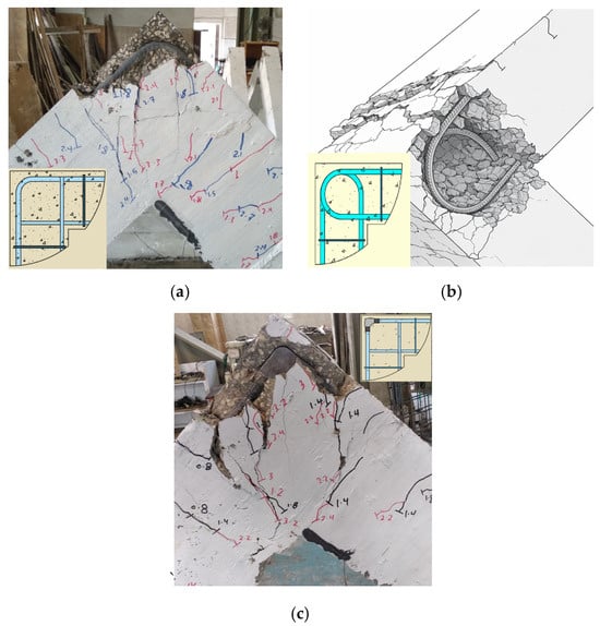
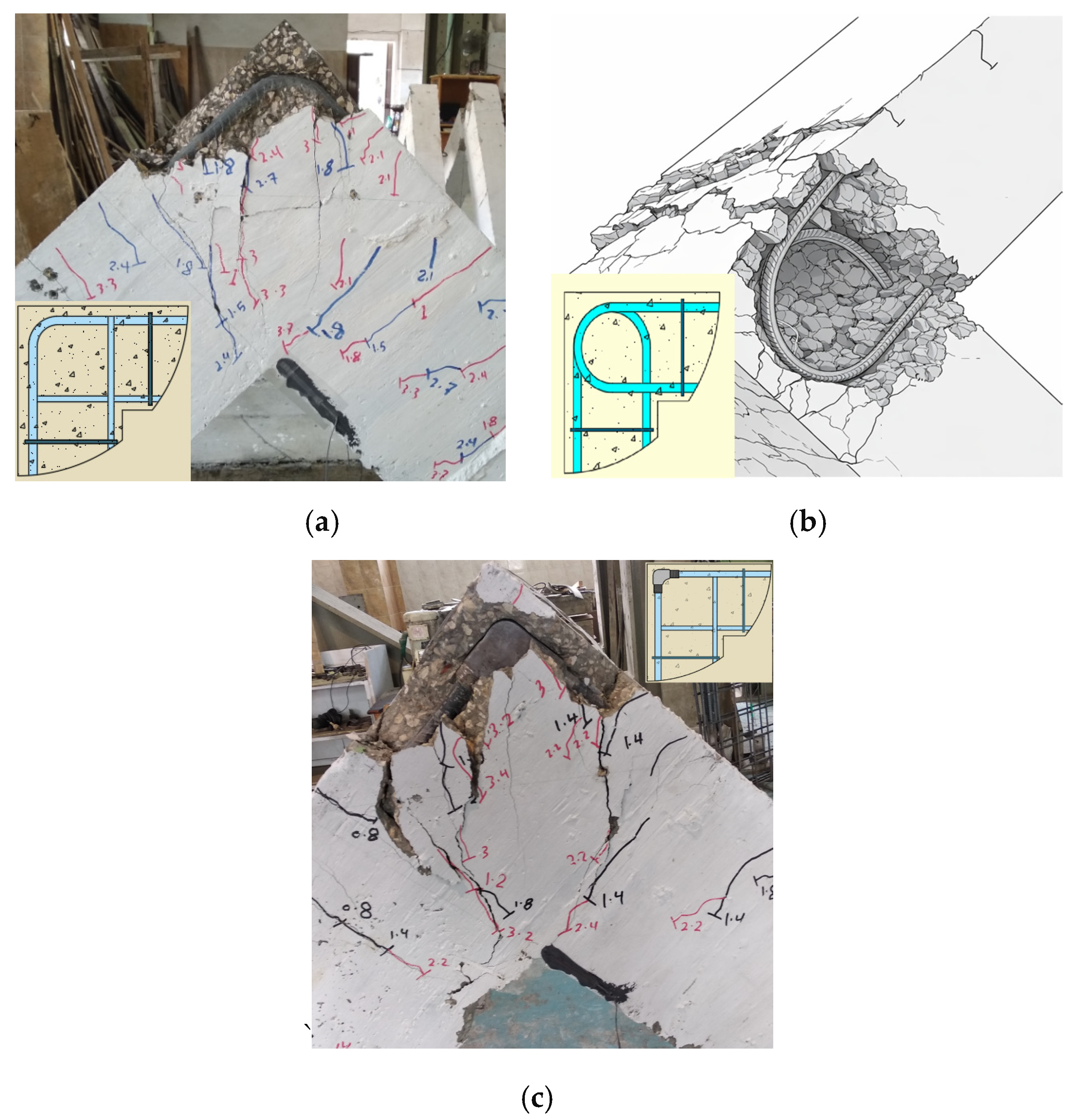
Traditional reinforcement detailing within the knee joint relies on several methods, most commonly bending the main tension bars (Figure 1a) [1,2,3,4,5] or looping them (Figure 1b) within the knee joint [4,6,7,8,9]. The critical drawback is that the tensile forces transferred through the bent-bar zones generate radial compressive stresses causing lateral splitting forces, concrete cover spalling, and brittle failure [1,4,6]. Studies on varying the reinforcement ratio [9,10,11] reported that higher ratios also led to brittle failure. Other investigations introduced inclined stirrups aligned with the diagonal strut [12], achieving improved ductility and reducing crack propagation. To address the shortcomings of these details [1], L-shaped mechanical couplers (Figure 1c) were successfully used instead of bending bars in the knee joint, which improved ductility, stiffness, and load capacity. Instead of bending, headed bars were added at the ends of the tension bars in the knee joint [13], resulting in load capacity results for the knee joint similar to traditional reinforcement methods. There are also innovative methods utilizing multi-shaped plates to support joint corners [14]. Furthermore, the use of GFRP reinforcement to study the effect of seismic drift and energy dissipation [15], Ultra-High-Performance Concrete (UHPC) [16], Hybrid Fiber-Reinforced Concrete (HPFRCC) [17,18], FRP tubes [19], or retrofitting the knee joint by integrating 3D post-tensioned joint enlargement [20] all led to notable improvements in joint ductility and cyclic response. In addition, precast corner joints with slabs under bidirectional loading [21] were studied. Also, predictive shear models [22,23] for the knee joint were developed using soft computing and regression techniques. Despite the significant improvements achieved by some of these approaches, failure is still governed primarily by the joint region, while ductility and energy dissipation remain limited, confirming that improving joint strength alone is not sufficient to ensure fully satisfactory structural performance.
Figure 1.
Failure mode for specimens with different details subjected to closing moment. (a) Traditional reinforcement detail [1]; (b) looping the main reinforcing bars [6]; (c) L-shaped coupler instead of bending tension bars [1].
This limitation encourages the search for different reinforcement details that can significantly change how loads are transferred within the joint area, rather than just making minor superficial changes. In this context, truss-shaped reinforcement systems offer a promising avenue, as they have the potential to redistribute internal forces through a rigid structural skeleton rather than relying on the concrete medium alone.
There are currently no experimental studies that have examined the use of truss-shaped reinforcement for the frame knee joint responsible for transferring stresses generated by opening and closing moments between the beam and the column. However, related studies have examined hybrid steel trussed–concrete beams, beam–column joints with truss-shaped reinforcement, and hybrid columns subjected to cyclic loads [24,25,26,27,28,29]. In one type of reinforcement used for the column-beam joint area, traditional stirrups surrounded continuous vertical reinforcement for the column, while the truss-shaped reinforcement on the connected beams was limited to the beginning of the column. Another type of reinforcement involves truss-shaped reinforcement within the joint, extending beyond to overlap with the truss reinforcement in the connected beams. As concluded by Monaco et al. [30], the behavior of the beam–column joint was significantly influenced by degradation phenomena in the panel zone due to the small depth of the beam associated with a large amount of longitudinal reinforcement passing through the joint. Pronounced pinching effects were revealed in almost all specimens tested in the different experimental campaigns, limiting the energy dissipation capacity of the structure.
In this paper, an experimental study was conducted to investigate the behavior of a frame knee joint reinforced by truss-shaped reinforcement. To check the applicability and reliability of the suggested reinforcement system, a full-sized specimen was fabricated and tested. It was reinforced with two parallel trusses, featuring simple mechanical joints along with tension and compression diagonals at the knee joint. The specimen was exposed to closing quasi-static loads, and the outcomes were compared with those from three specimens that were reinforced using traditional reinforcement details. These included variations with and without stirrups in the knee joints, as well as different grades of concrete.
2. Preliminary Investigation of Internal Force Distribution in the Truss System
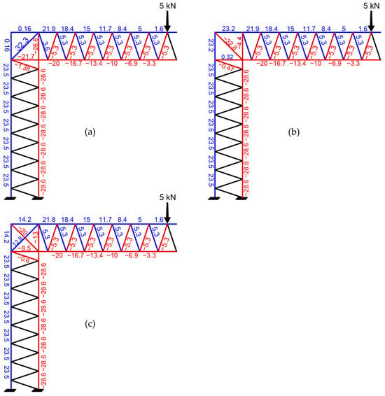
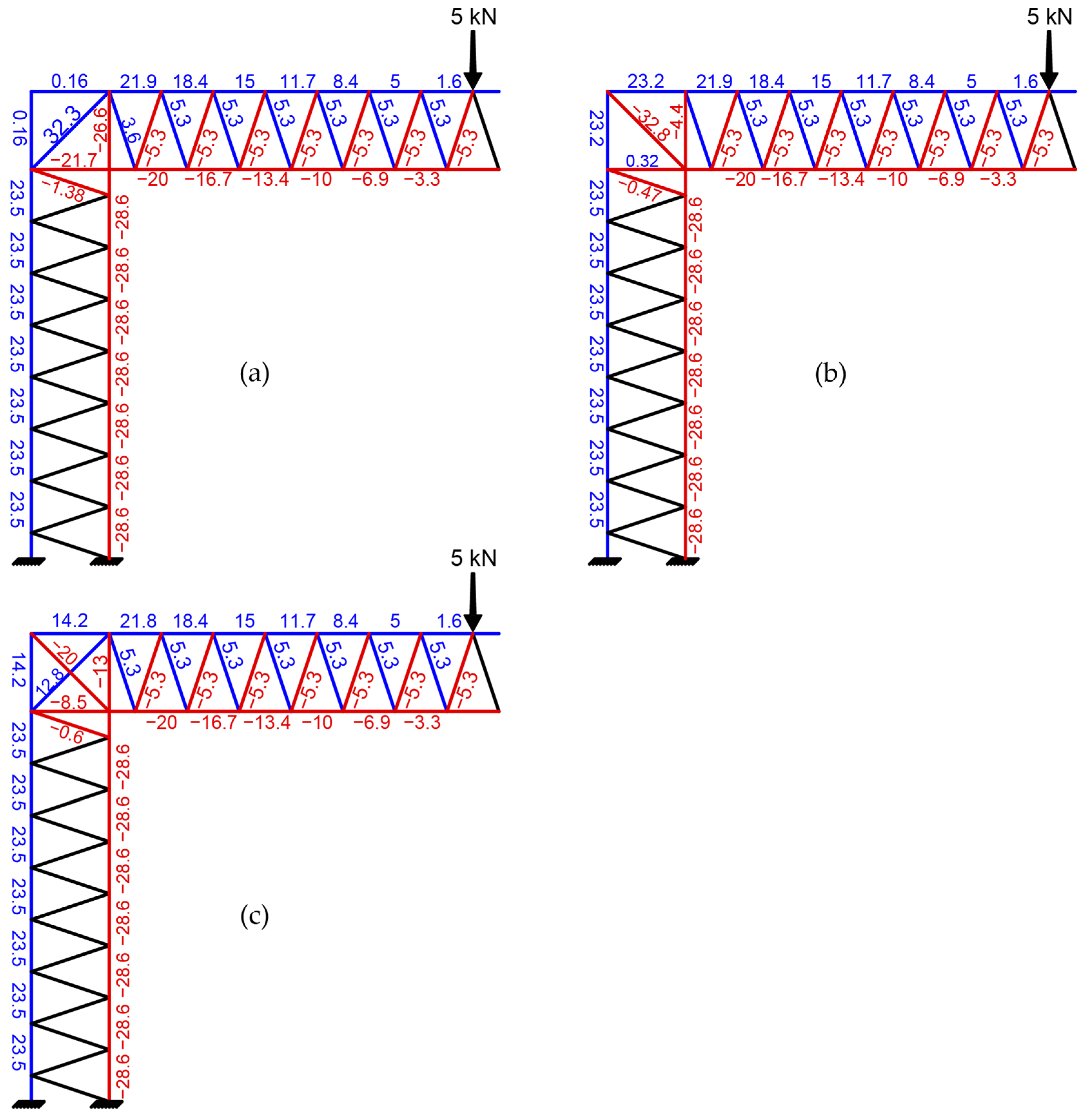
In conventional reinforced concrete structures, stress is transferred between reinforcing bars through the concrete medium, either by lap splices or by the internal equilibrium coupling tension and compression zones. Unlike conventional reinforcement, truss reinforcement functions as a unified entity in response to external loads. The configuration and distribution of truss members, along with the magnitude of external applied loads, dictate how forces are distributed among the joints of the truss skeleton. Numerical analyses were conducted to assess the impact of diagonal members within the knee joint on the internal force distribution of truss members. For a pair of parallel trusses subject to a 10 kN vertical downward load near the end of the truss arm, calculations were performed to evaluate the normal forces in cases involving diagonal tension and compression members as illustrated in Figure 2a,b. The diagonal members resist significant portions of the tensile and compressive forces within the truss system. The best distribution of normal forces occurs when both tension and compression diagonals are simultaneously present, as illustrated in Figure 2c. Adding diagonal tension bars helps by diverting a significant amount of the tensile force from the main tension bars to the knee joint area. This mechanism reduces diagonal splitting forces, protects against early yielding of the main bars as well as concrete spalling in the bent-bar region. Additionally, it decreases the internal force in the diagonal compression strut of the knee joint.
Figure 2.
Normal forces in truss members with and without presence of diagonals in knee joint: (a) diagonal tension; (b) diagonal compression; (c) diagonal tension and compression.
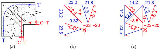
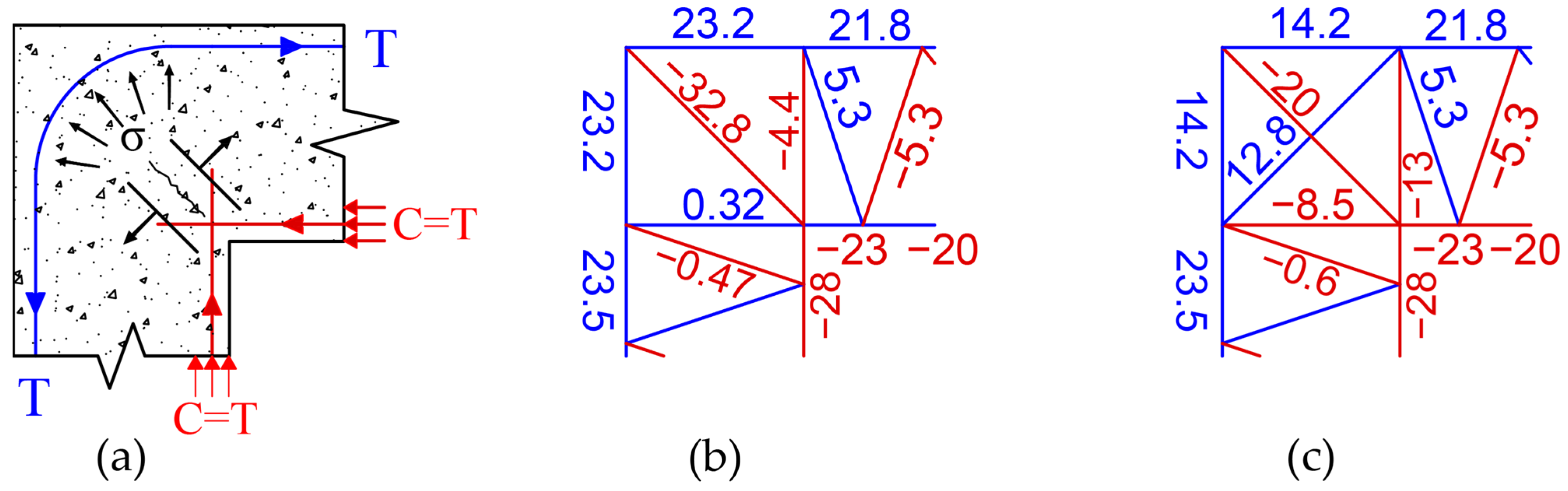
In this study, the primary tension reinforcement bars of the reference specimens (R1, R2, and R3) are bent at the top end of the knee joint. The tensile force at the critical section is labeled as T, while the compression force C follows the typical truss mechanism. When these specimens experience a closing moment, the tensile forces transferred through the bent-bar regions create a concentration of radial compressive stresses at the bent bar’s inner radius. These stresses, together with the compression force C resulting from the truss action, generate a diagonal tension splitting force , as shown in Figure 3a.
Figure 3.
Normal forces in knee- joint rebar detailing. (a) forces according to strut and tie mechanism; (b) forces according to numerical analysis with a diagonal compression member; (c) forces according to numerical analysis with diagonal tension and compression members.
Based on the numerical analysis of the truss, the maximum tensile force calculated in the top reinforcement was 21.8 kN. In the proposed truss system, this force is safely distributed among the truss members upon entering the corner joint, thereby avoiding localized stress concentration. To demonstrate the mechanical necessity of this system, the same peak value (21.8 kN) can be used to simulate the force-transfer mechanism in a conventional system that lacks diagonal elements. Assuming the tensile force in the main reinforcement bar, T, equals 21.8 kN, the corresponding compression force, C, in the traditional truss analogy generates a diagonal compressive force calculated as . This analysis clearly demonstrates that, in the absence of diagonal elements, the conventional load path inherently produces very large diagonal compressive forces within the corner joint, while simultaneously allowing the concentration of critical tensile stresses in the bent-bar region.
Figure 3b,c illustrate the normal forces in the knee joint truss members resulting from the numerical analysis of the truss shown in Figure 2. The output force in the diagonal compression resulting from the traditional truss mechanism (30.8 kN) is slightly less than that resulting from the forces in the truss in Figure 3b. This may be due to the presence of compression members at critical sections in the system. A comparison between Figure 3a and Figure 3c shows that the normal forces in the main tension bar decreased by 54% due to the presence of diagonal tension.
3. Experimental Program
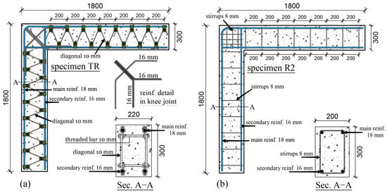
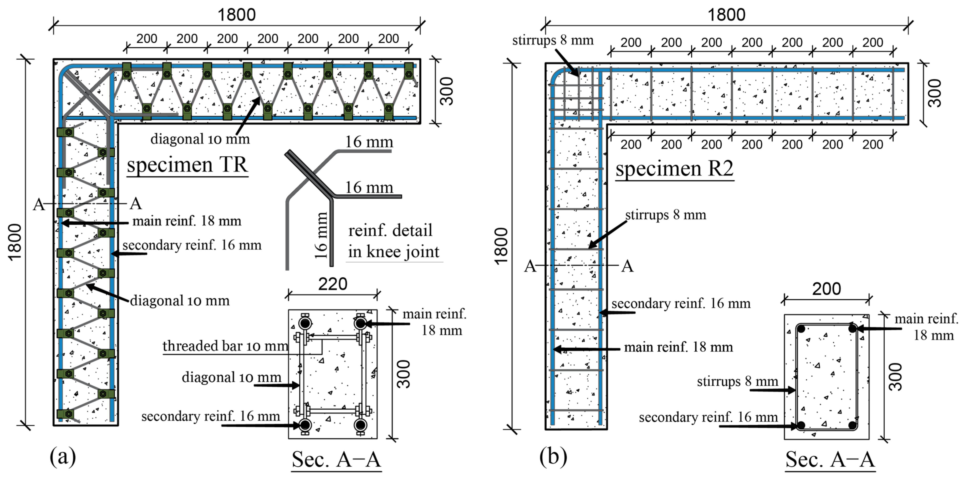
The test specimen (TR), featuring a novel reinforcement system, illustrated in Figure 4a, was fabricated and tested under quasi-static loading conditions in comparison to three conventional specimens (R1, R2, and R3) outlined by Al-Tuhami et al. [1]. Both the new and traditional specimens had the same main tension and compression reinforcement areas. The only difference was that the TR was 20 mm wider than the traditional specimens.
Figure 4.
Specimen dimensions and reinforcement details. (a) Proposed reinforcement detail; (b) traditional reinforcement detail for specimen R2.
The length of both the beam and column was set at 1800 mm, with traditional specimens (R1, R2, and R3) having cross-sectional dimensions of 200 mm × 300 mm, while the proposed specimen (TR) had dimensions of 220 mm × 300 mm. All traditional specimens shared similar reinforcement details, except for specimen R2, which featured horizontal and vertical stirrups in the knee joint, as illustrated in Figure 4b. The reinforcement setup of the proposed specimen included two parallel trusses, each with primary and secondary reinforcing bars (truss chords) measuring 18 mm and 16 mm in diameter, respectively. Additionally, there were inclined diagonal bars with a 10 mm diameter, bent over fixed horizontal threaded rods that also measured 10 mm in diameter at each joint, creating a V-shaped arrangement. These diagonal bars were also used for grouping and securing the two parallel trusses together. The knee joint of the truss included two adjacent bars (16 mm diameter each) in the joint diagonal strut and an additional bar for diagonal tension, with diagonal compression bars intersecting the diagonal tension bars. The knee joint detail was selected for cost-effective reasons, though the recommendation was made to connect all truss members or bars through truss coupler joints, as proposed in the future work of this paper.
The specimen labeled TR, which utilized a proposed truss reinforcement system, had a concrete grade of 45 MPa, compared to specimens R1 and R2, which both had a concrete grade of 34 MPa. Specimen R3 had a concrete grade of 55 MPa. The specifics regarding the details, configurations, and features of these specimens are outlined in Table 1.
Table 1.
Detailed information, dimensions, reinforcements, and concrete grades of the tested specimens.
3.1. Materials
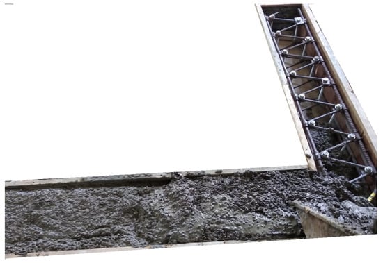
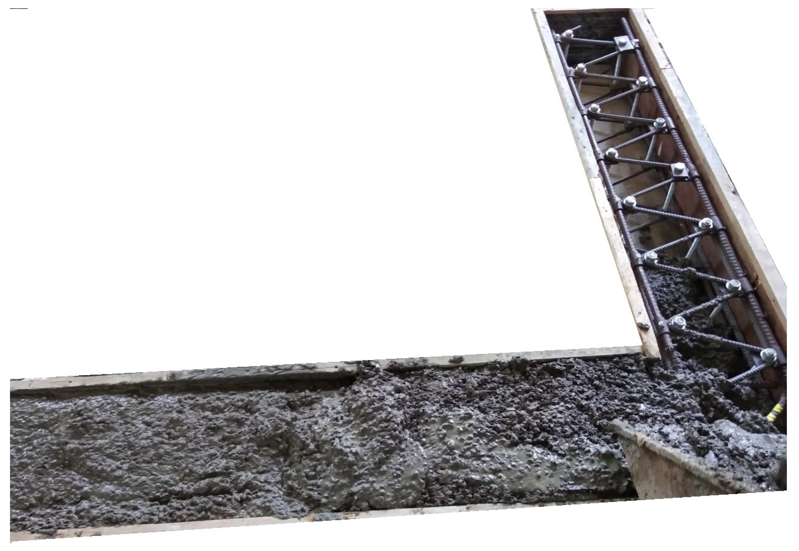
The main tension bars utilized for reinforcing tension in the test specimens were ribbed bars of the B400DWR grade, as per the international standard [31]. Tests conducted on the reinforcing bars utilized for tension and compression demonstrated an average yield strength of 400 MPa and an average ultimate strength of 570 MPa. The concrete cube compressive strength of the proposed specimen at the time of testing was recorded at 45 MPa. Figure 5 illustrates the proposed specimen and its reinforcement during the concrete casting process. The knee details and corresponding concrete strengths of different test specimens can be viewed in Table 1.
Figure 5.
Concrete casting of the proposed specimen reinforced with a rebar truss system.
3.2. Test Setup and Instrumentations
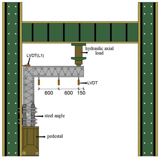
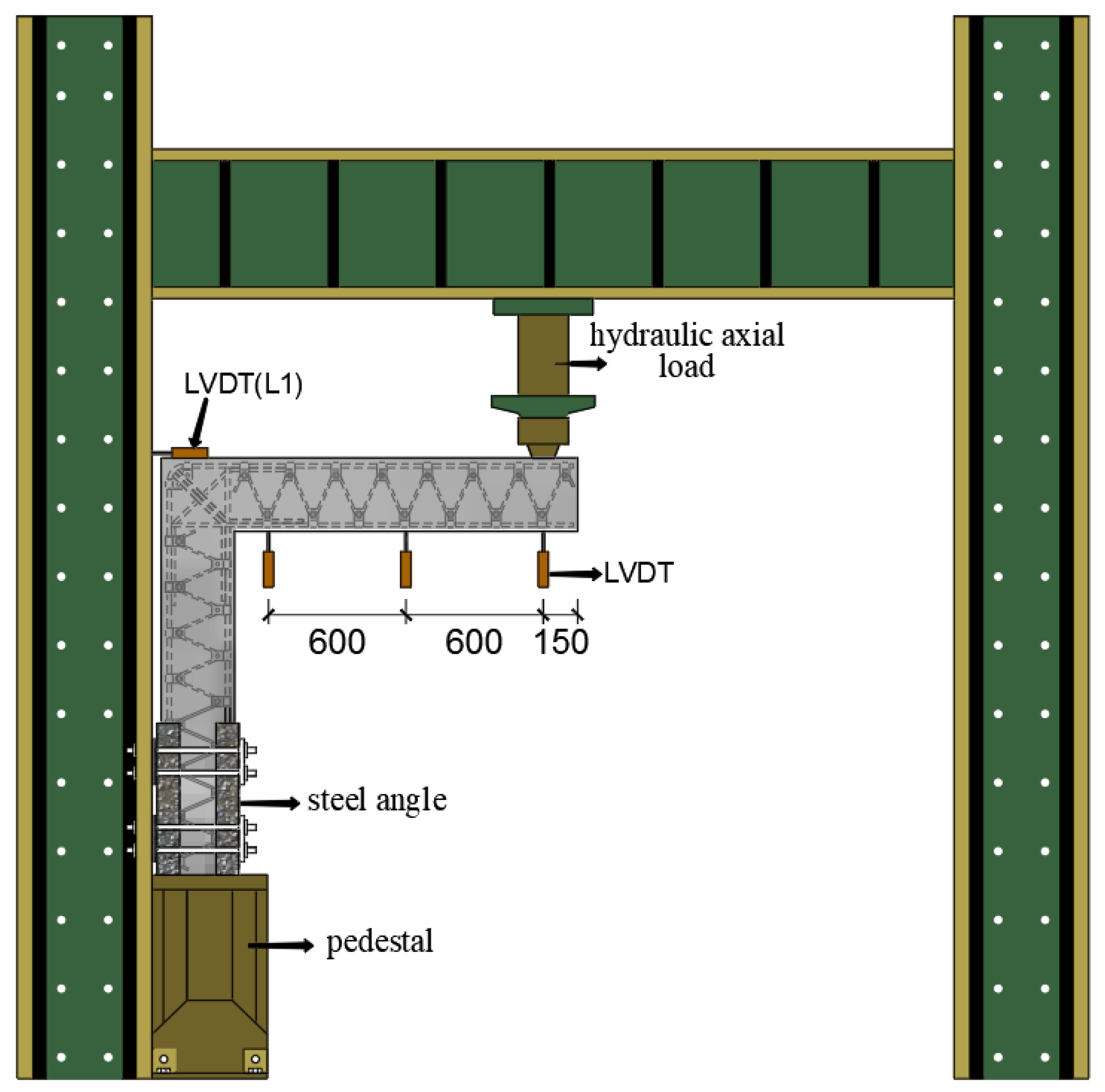
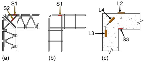
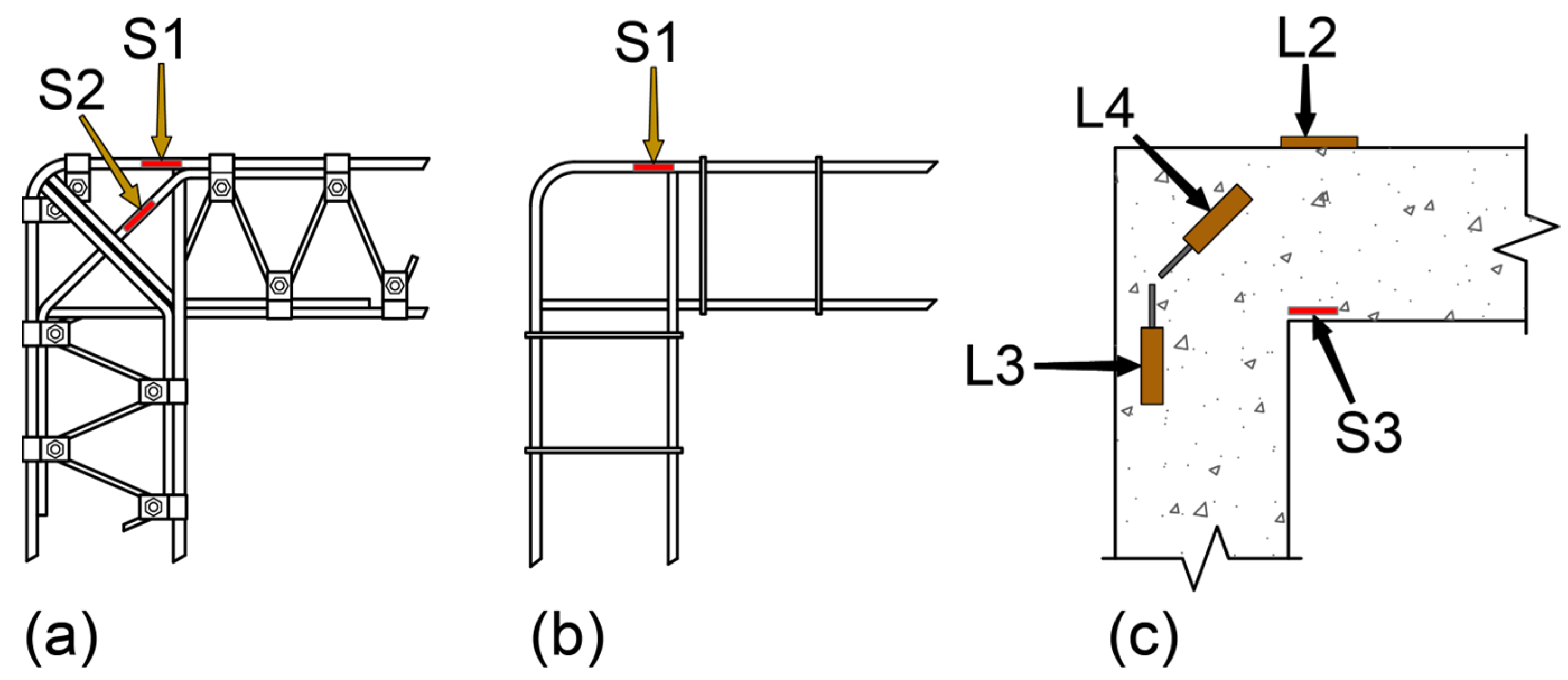
All the experimental tests were carried out at the Concrete Experimentation Laboratory of Ain-Shams University on all specimens, including the proposed (TR). Some of the results related to the reference specimens used in this study for comparison with the specimen reinforced with the proposed reinforcement system were mentioned in the study conducted by [1]. The load was applied using a hydraulic jack with a load capacity of 150 kN (RAM-PAC International, Inc., Houston, TX, USA), positioned at the end of the beam to load the specimens until failure. The load was applied monotonically in increments. At each step, the load was increased to a predetermined value and then lowered to zero while strain and deflection readings were recorded, then increased to the next level until failure. Strain and deflection measurements were recorded at the conclusion of each load increment. To measure vertical displacement, three linear variable displacement transducers (LVDTs) were utilized for each tested specimen. The first LVDT was positioned beneath the loading point at the end of the beam, while the other two were located at the mid-span of the beams and near the joints. Additionally, an LVDT was placed at the top of the knee joint to measure horizontal displacement. The load applied was monitored using an electrical load cell (Controls S.r.l., Milan, Italy). The experimental setup and the locations of the LVDTs are illustrated in Figure 6. Internal electrical strain gauges (S1) were installed on the surface of the main tension bars at the beam-to-knee-joint connection for all specimens, as illustrated in Figure 7a,b. An additional internal strain gauge (S2) was attached to the diagonal tension bar in the TR, as shown in Figure 7a.
Figure 6.
Test setup.
Figure 7.
Locations of both internal and external strain gauges and LVDTs used for crack width measurements. (a) locations of internal strain gauges installed in the specimen (TR); (b) locations of internal strain gauges installed in the traditional specimens; (c) locations of crack width measurement devices (LVDTs) and external strain gauges in all specimens.
Three LVDTs (L2, L3, and L4) were placed to measure crack widths, as indicated in Figure 7c; the first (L2) was positioned outside the beam-to-joint connections, the second (L3) was placed at the column-to-joint connection, and the third was located at the diagonal compression strut. A data logger was utilized to connect all LVDTs, load cells, and strain gauges for the purpose of gathering and analyzing data.
4. Experimental Results and Discussion
This section discusses how the four tested specimens performed structurally, focusing on their load-deflection behavior, strain readings in the concrete and primary reinforcement bars, crack patterns, and failure modes.
4.1. Failure Mode and Cracking Pattern
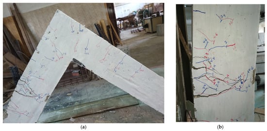
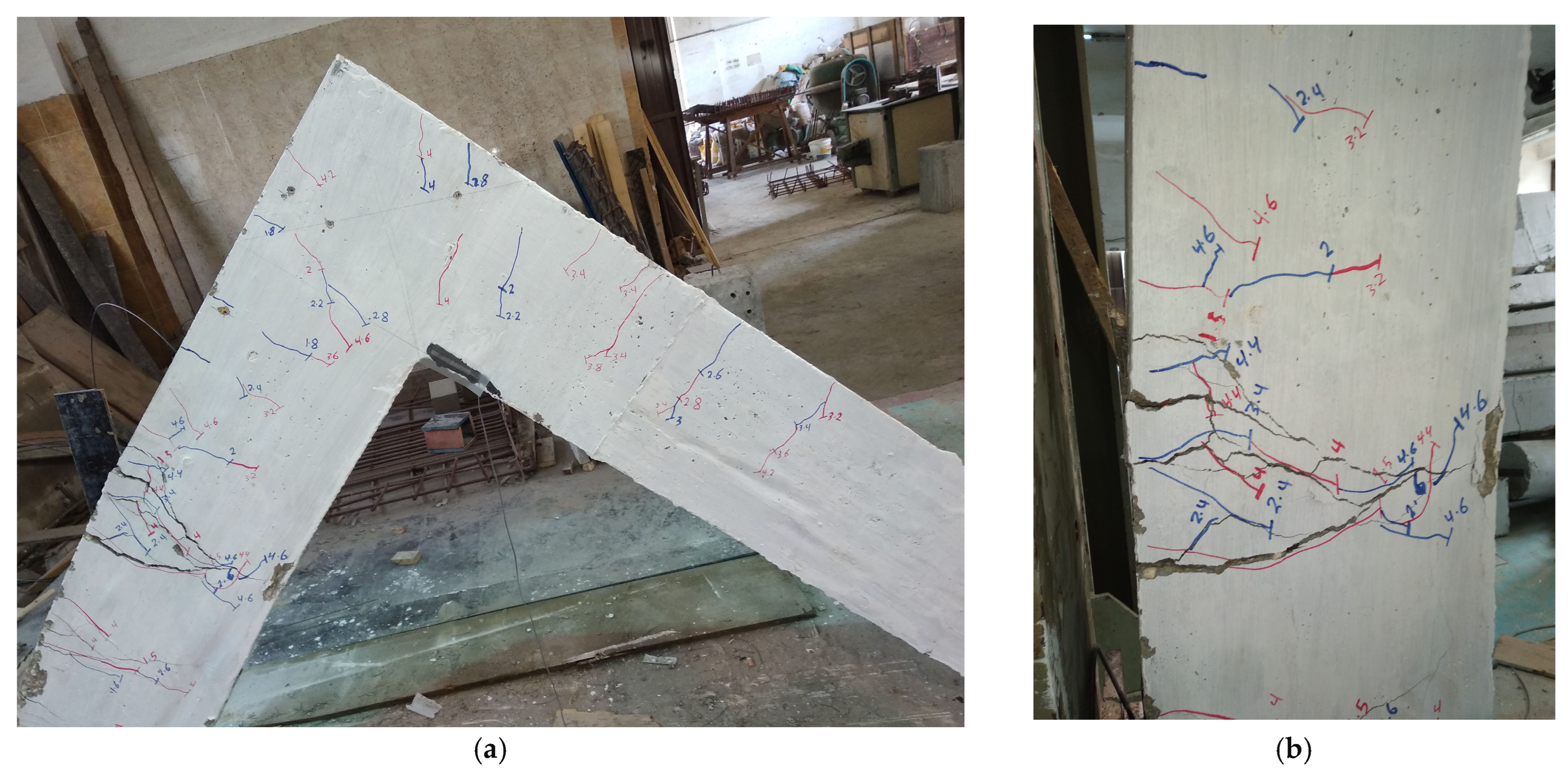
In the suggested TR, three flexural cracks emerged in the center span area of the column at a load of 7 kN (fcu = 45 MPa). With the increase in load, the flexural cracks gradually increased and extended throughout the column and beam, primarily concentrating in the central area of the column as shown in Figure 8. The cracks visibly expanded and deepened along the outer face in the middle of the column. The loading was stopped at 51.01 kN in order to avoid a potential sudden failure that may have occurred. Utilizing truss-shaped reinforcement and incorporating tension and compression diagonals in the knee region led to the shift in failure cracks from the knee joint to the middle section of the column. The number and width of cracks in the knee joint region significantly reduced to almost none, to the point of being virtually eliminated, accompanied by a noticeable improvement in stiffness.
Figure 8.
Crack pattern of the specimen reinforced with the proposed truss-reinforced at the end of loading. (a) Crack pattern of the knee joint and adjacent portions; (b) a close-up of the failure cracks in the column area.
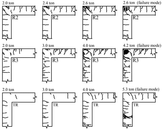
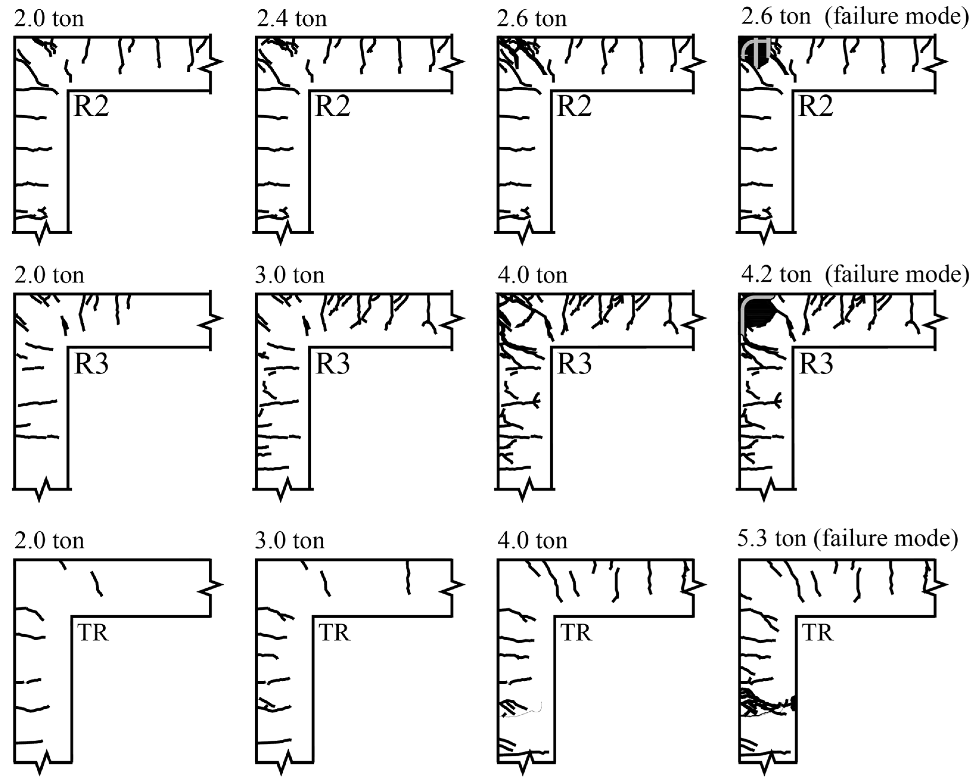
Regarding the crack propagation mechanism in the tested specimens as illustrated in Figure 9, it was observed at a load of 20 kN that the crack propagation rate was significantly higher in specimen R2 in the beam, column, and knee joint. Crack propagation was also present, but at a lower rate, in specimen R3 compared to specimen R2. On the other hand, the specimen with truss reinforcement showed very little crack growth. There were almost no cracks in the beam and knee joint, and only a few minor cracks could be seen in the column. As the load increased, cracks developed significantly in specimen R2, and cracks widened in the knee joint. The concrete cover also spalled at the knee joint, and the specimen collapsed in a brittle manner before the load reached 30 kN.
Figure 9.
The crack patterns evolved with increasing load up to the failure stage for the tested specimens R2, R3, and TR.
For specimen R3, cracks propagated more widely along the entire length of the beam and column at a load of 30 kN, while for the truss specimen, no significant crack propagation was observed even when the specimen reached 30 kN. As the specimen R3 experienced a load of 40 kN, the cracks became wider and deeper at the knee joint, with the concrete cover starting to separate at that area. The specimen eventually failed under a load of 42 kN. On the other hand, the truss specimen showed very restricted crack growth. Few cracks spread along the beam at a load of 40 kN, and the truss specimen continued to bear additional loads. When the truss specimen reached a load of 50 kN, cracks began to appear in the column near the support, while the crack propagation rate in the beam and knee joint remained negligible. When the load reached 51 kN, the crack width near the support became wider and deeper, and the applied loading was stopped because the concrete near the support began to crush at constant load without any failure of the specimen. The findings clearly show that the truss reinforcement system greatly decreased the occurrence and spread of flexural cracks in both the beam and column. The suggested knee-joint detailing substantially reduced cracking in the joint area and avoided any brittle failure there. On the other hand, in specimens with conventional detailing, the knee joint was a critical weak spot, and significant cracking was also seen in the nearby beam and column.
4.2. Load–Displacement Response
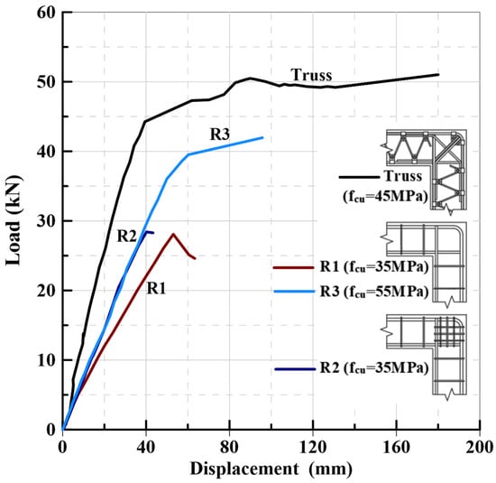
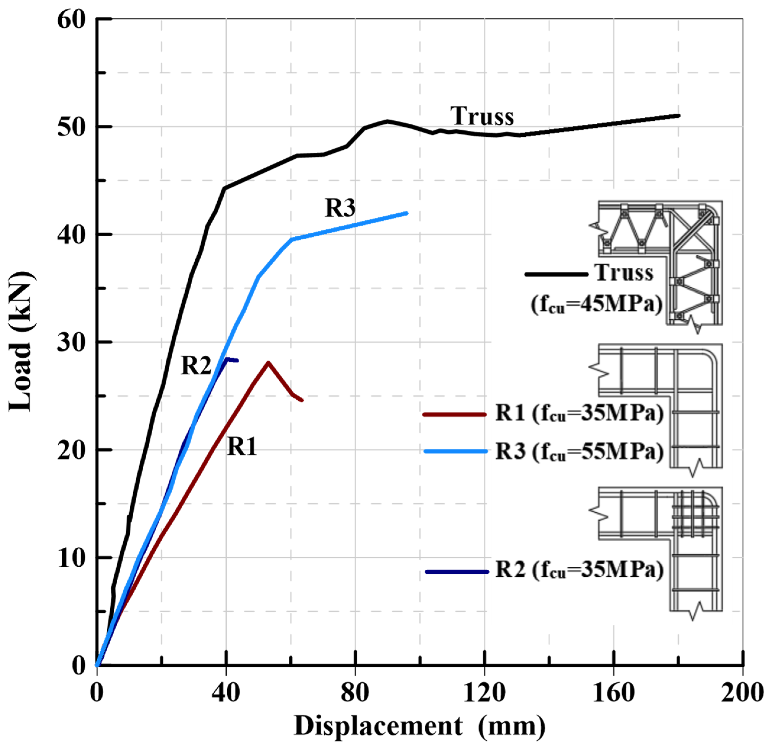
Figure 10 displays the relationship between the load and displacement of different tested specimens: traditional specimens R1 and R3, the traditional specimen with stirrups R2, and the specimen reinforced with a truss system. Displacements at ultimate loads were measured at 53.06 mm, 40.20 mm, 95.70 mm, and 180 mm for the test specimens R1, R2, R3, and TR at loads of 28.08 kN, 28.41 kN, 41.95 kN, and 51.01 kN, respectively. The specimen containing the truss reinforcement system exhibited a significantly higher ultimate load compared to those with conventional reinforcement details (R1, R2, and R3), showing an increase in load capacity of approximately 81%, 79%, and 21%, respectively. In terms of displacements at yield load, the test specimens (R1, R3, and TR) displayed values of 48.36 mm, 47.34 mm, and 34.24 mm at loads of 26.09 kN, 34.36 kN, and 44.5 kN, respectively. The specimen utilizing the truss reinforcement system (TR) demonstrated a higher yield load at lower displacement compared to those with traditional reinforcement detail (R1 and R3), showing an increase in yield load capacity of about 70% and 29%, respectively. Moreover, the specimen reinforced with the rebar trusses (TR) demonstrated a smaller yield displacement compared to specimen R3, even though it bore a higher yield load, showing a significant enhancement in stiffness. It is clear that the truss-reinforced specimen showed a tendency to harden instead of soften after initial cracking occurred. Furthermore, the truss specimen demonstrated greater stiffness than all specimens with conventional reinforcement details (R1, R2, and R3), with increases of about 126%, 70%, and 72%, respectively. Moreover, the truss specimen showcased significantly higher displacement capacity in comparison to all other specimens (R1, R2, and R3) by 239%, 347%, and 88%, respectively. In this regard, the proposed specimen achieved a markedly higher displacement ductility index (μΔ = 5.25) than the traditional specimens (μΔ = 1.09–2.02), corresponding to an increase of approximately 160–382%. The ultimate load-carrying capacity obtained from testing the truss-reinforced specimen (TR) with a compressive strength of 45 MPa was 51.01 kN, whereas the analytically estimated capacity based on force equilibrium was 28 kN. The test results, knee efficiency, and failure mode of both the conventional and proposed specimens are summarized in Table 2.
Figure 10.
Load–displacement relationship of various tested specimens.
Table 2.
Test outcomes, efficiencies, and modes of failure for the tested specimens.
The displacement ductility index achieved by the proposed specimen (μΔ = 5.25) significantly exceeds the values documented in earlier research on conventional knee joints. This includes studies involving L-shaped couplers [1] and looped reinforcement [10]. Furthermore, the relocation of the failure zone from the joint region to the adjoining column signifies a qualitatively better performance outcome that has not been previously noted in experimental studies on RC knee joints.
4.3. Load–Strain Relation
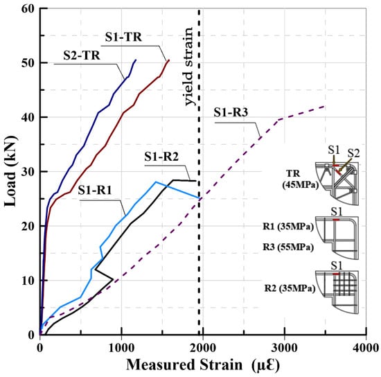
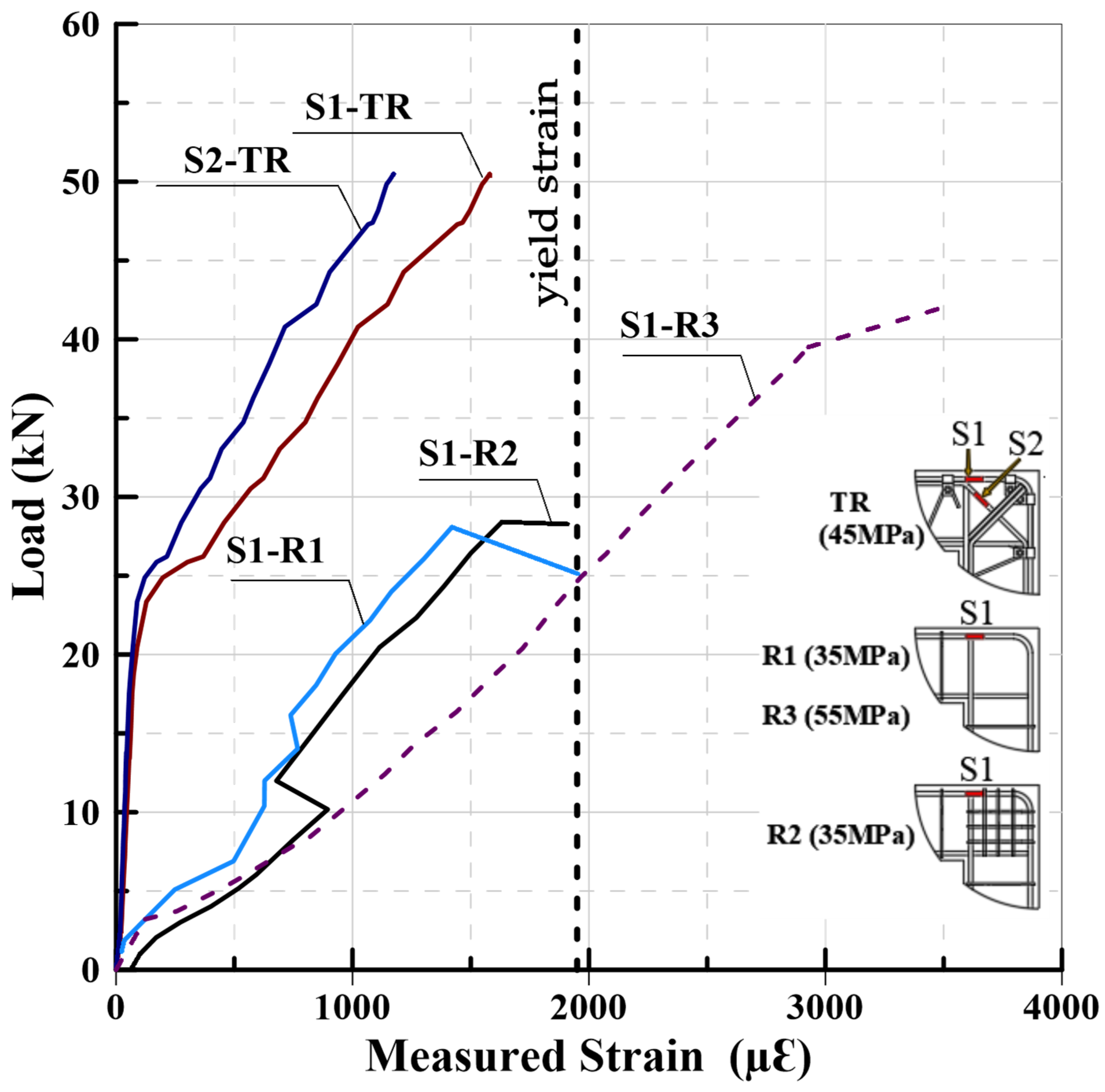
The steel strain–load graph presented in Figure 11 was obtained from internal strain gauges installed on the main tensile reinforcement (S1) in all specimens, with an additional gauge (S2) on the diagonal tension bar of the truss-reinforced specimen (TR) to evaluate the stress transferred to this member. The strain readings for S1 and S2 in the truss specimen (TR) reached 1600 µε and 1200 µε, respectively, at a load of 50 kN. This suggests that the tensile stresses imposed on the knee joint are distributed between both the main and diagonal tensile bars, ensuring that the primary rebar stress remains below the yield point. As a result, the intensity of cracks decreased significantly, and the few cracks that did appear were relatively narrow. On the other hand, specimens with traditional reinforcement showed higher strain values (3484 µε) in the main tensile bar of specimen R3 when subjected to a load of 41.95 kN, exceeding the yield level. In specimens R1 and R2, the strain values reached the onset of the yield point at lower loads, indicating high stress concentration in upper tensile bars. It is clear that the suggested reinforcement skeleton and specifics in the specimen with a truss-reinforced shape (TR) successfully redistributed a significant portion of the tension stress away from the bent main bar, greatly improving joint efficiency.
Figure 11.
Applied load vs. measured strain in the main tension reinforcement bar in all specimens and in the diagonal tension bar in the proposed truss specimen.
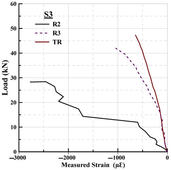
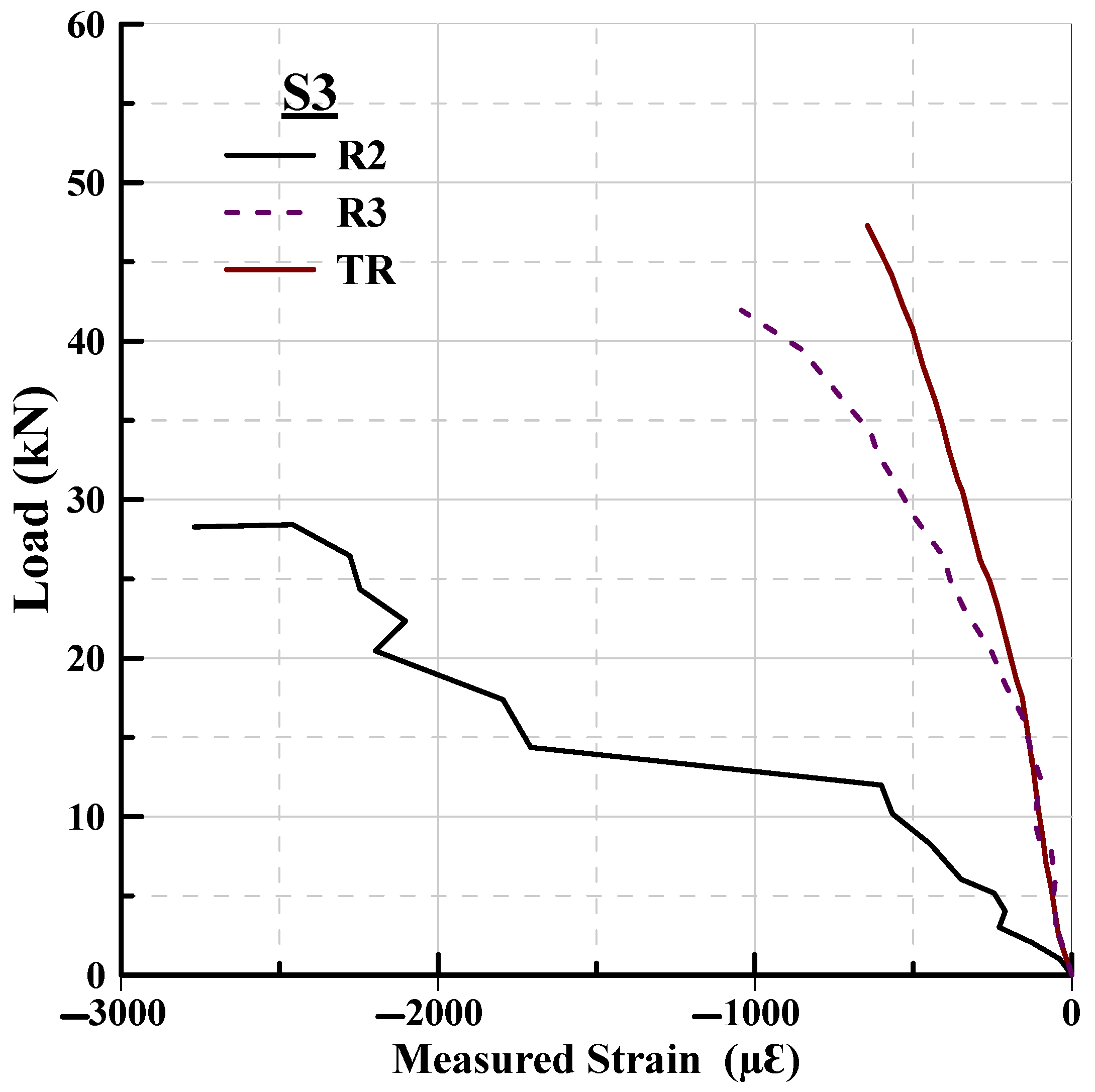
Figure 12 illustrates the relationship between the applied load and the measured compressive strain on the concrete surface near the inner corner of the corner joint for specimens R2, R3, and TR. The data show a significant difference in response. In the traditional specimen (R2), the compressive strain increased sharply to approximately 2800 µε at a load of approximately 28 kN, a value close to the ultimate design crushing limit of concrete (3000 µε). For specimen (R3), despite its improved performance due to the higher strength of the concrete, it exhibited a significant strain of approximately 1100 µε at 41.95 kN. In contrast, the truss-reinforced specimen (TR) showed a very stiff response. Even at a maximum load of 51 kN, the compressive strain did not exceed 650 µε. This behavior confirms that the rigid truss skeleton absorbs the majority of the internal forces resulting from the applied load, while the surrounding concrete primarily functions to confine the truss members and prevent their buckling. Thus, the innovative system successfully protects the inner corner of the joint from concentrated bearing stresses, preventing premature failure due to concrete crushing.
Figure 12.
Load vs. concrete strain at the inside surface of the knee joint for the proposed specimen TR and the reference specimens, R2 and R3.
5. Analytical Strength Prediction of Closing Knee Joint
The theoretical prediction of the ultimate strength of the tested specimens requires identifying the governing failure mechanisms within the corner joint and adjacent members. Previous approaches, such as Nilsson and Losberg [32], define joint efficiency based on the ratio between experimental and calculated moments; however, these methods do not adequately capture the complex stress distribution in disturbed regions (D-regions) nor account for serviceability-related limitations. In this research, a stress-block method is utilized for the neighboring elements, whereas a strut-and-tie model (STM) is employed to depict the internal force transmission system in the traditional knee joint. To examine the distribution of internal forces in the suggested TR, a simplified truss-based finite element model is employed, and the related capacities are evaluated theoretically utilizing strut-and-tie principles. The strut-and-tie method (STM) has been proven to be highly effective for analyzing disturbed stress regions (D-regions) such as closing knee joints, consistent with recent analytical advancements and frameworks proposed by Wang [33]. The overall free body diagram is displayed in Figure 13.
Figure 13.
Global free body diagram for the tested specimens.
5.1. Proposal for a Conceptual Strut-And-Tie Model for Traditional Specimens
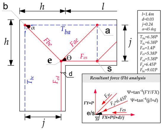
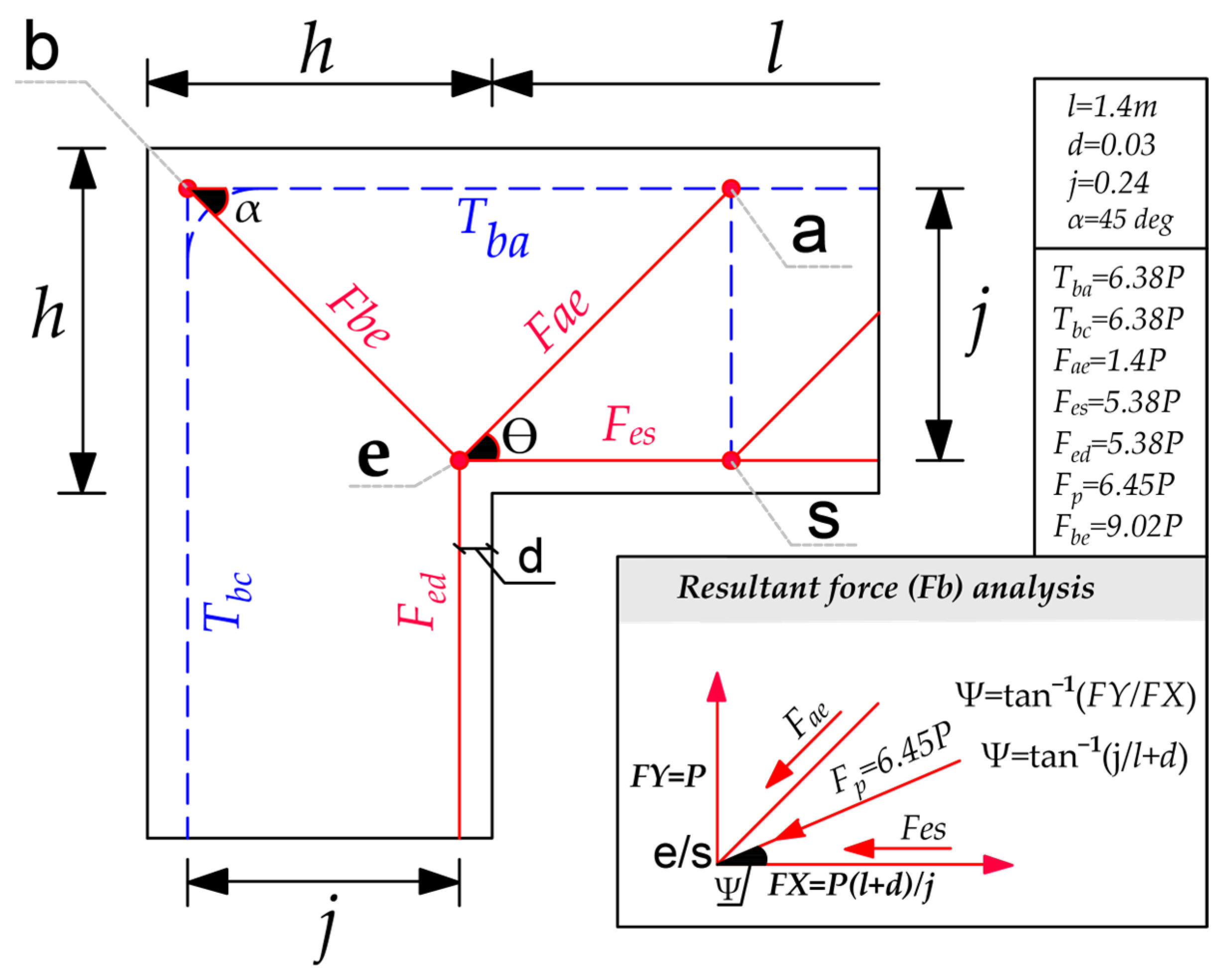
Figure 14 depicts the typical trajectory of normal forces within a corner joint. Additionally, the magnitudes of the normal forces are evaluated in the force paths and nodes that are subject to critical stresses.
Figure 14.
Proposed strut-and-tie model for the corner joint, illustrating the internal normal forces and their resultant in traditional specimens. (Note: blue dashed lines indicate tension ties, while red solid lines denote compression struts.).
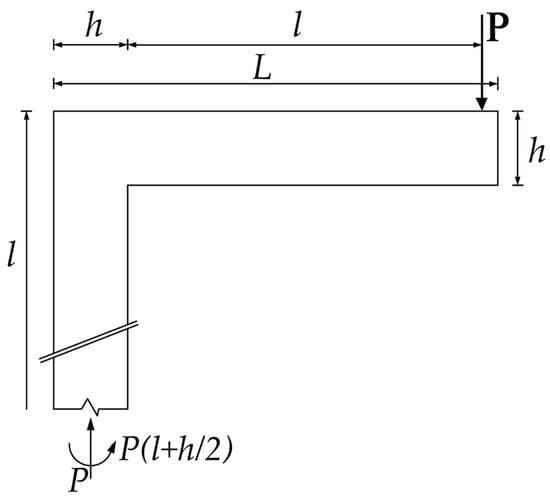
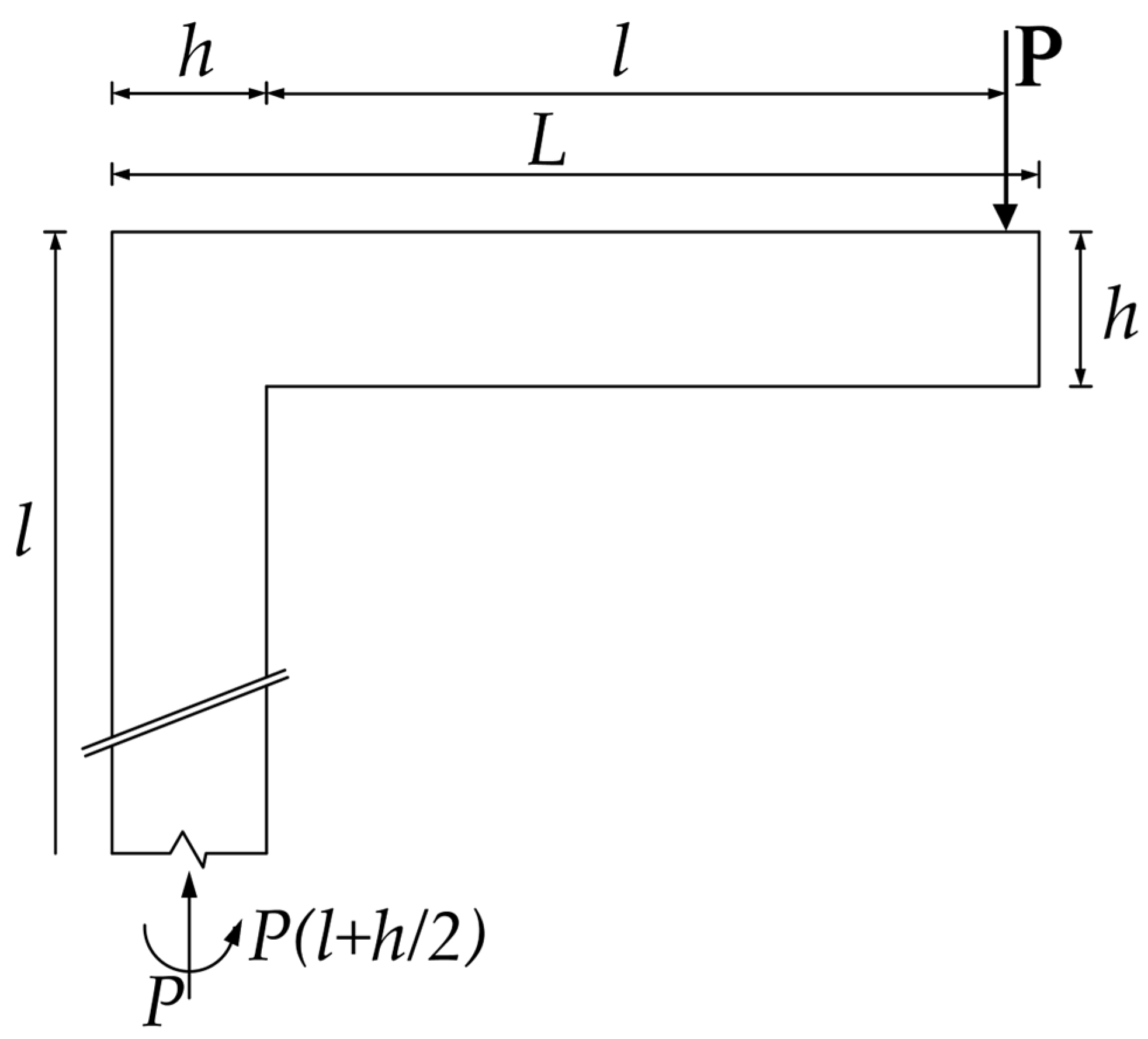
According to the global equilibrium of moments, the main tensile forces produced in the horizontal and vertical main reinforcement ties ( and , respectively) depend on the external applied load (P), the moment arm (), the geometric offset dimension (), and the internal lever arm (). This relationship can be expressed as
Here, α is set at 45° due to the square geometry of the joint, making cot (α) = 1, and j stands for the effective internal moment arm of the section, which averaged 240 mm in the tested specimens.
To ensure vertical equilibrium at the outer segment of the beam, the vertical component of the main diagonal compressive strut must equal the external applied load (P). Hence, the force in this strut is computed as follows:
Since θ equals 45°, the necessary capacity of the strut reduces to being 1.41P. In addition, to ensure equilibrium at the node, the internal forces in the nearby horizontal and vertical compressive struts ( and ) are calculated using the equation given below:
The total horizontal force is calculated by adding the horizontal internal force () to the horizontal component of the diagonal compressive force (), and can be expressed by the following equation:
By replacing in Equation (3), the term transforms into . By utilizing this substitution and the value of from Equation (4) in Equation (5), the overall horizontal force FX reduces to
The internal force’s vertical components at the inner node (e) need to be equal to the applied load in order to maintain global vertical balance, as indicated by
As a result, the magnitude of the internal force acting on this crucial inner nodal area () is derived from its orthogonal components:
Incorporating the expressions for FX and FY into Equation (8) gives the generalized formula for the resultant force:
The equilibrium of node (b) was deduced from the capacity of the diagonal strut, which is directly influenced by the tensile tie force, and Fbe can be expressed by the following equation:
By substituting the value of from Equation (1), the magnitude of the main diagonal compressive strut becomes:
Based on the prior analysis, estimates were made for the normal forces acting within the corner joint. The tensile forces, both horizontal and vertical, labeled and , were found to be approximately Meanwhile, the horizontal and vertical compressive forces, were approximately equal, about each. Furthermore, the resultant force , arising from the combination of the horizontal compressive force and the diagonal compressive force , was approximately . In addition, the diagonal compressive force within the corner joint, labeled , reached approximately . The results are summarized in the following Figure 14.
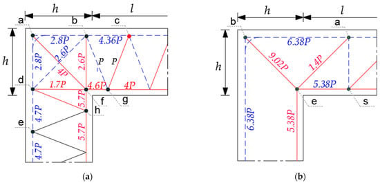
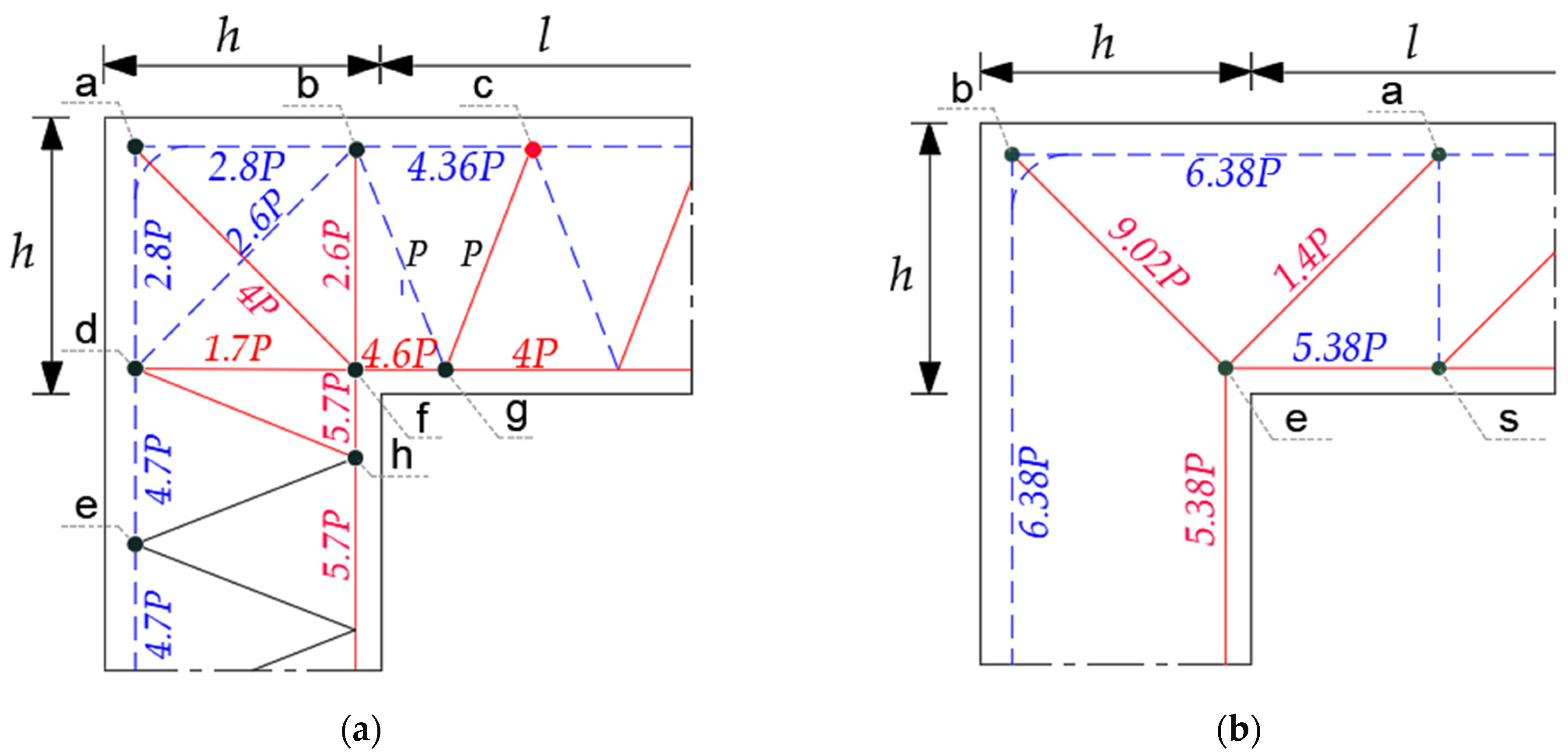
The reinforcement truss skeleton in the proposed TR is different from traditional reinforcement in reinforced concrete knee joints, as it acts as a single object encased in concrete. This leads to a unique load-transfer mechanism compared to the usual concrete strut-and-tie method, with the rebar truss playing a vital role in distributing loads for a safer and more uniform stress distribution, as shown in Figure 15. According to the FE analysis, internal axial forces were distributed more uniformly in the proposed TR. Specifically, the tensile force in the main reinforcement of conventional specimens was 6.38P, whereas in the proposed specimen, it decreased to approximately 2.8P. The truss reinforcement system between nodes (b) and (d) helped divert the remaining tensile demand, contributing to a decrease in stress concentration at the CTT node region near the bent-bar location. Furthermore, the axial compressive force at the corner joint was reduced from 9.02P in conventional specimens to a lower level of 4P in the proposed TR.
Figure 15.
Force distributions in both proposed and traditional specimens: (a) proposed specimen, truss model TR; (b) traditional specimen, strut-and-tie model. (Note: blue dashed lines indicate tension ties, while red solid lines denote compression struts.).
When the axial forces derived from the strains measured during the experiments were compared to the theoretical predictions from the analytically suggested models, using the steel’s elastic modulus of 200 GPa and a reinforcement area of As = 2ϕ18 = 508.9 mm2, a strong match was noted between the experimental and theoretical values, as illustrated in Table 3. For the traditional specimens, the measured tensile forces in the main reinforcement bars varied from 5.16P to 6.60P, while the theoretical value was 6.38P. Regarding the proposed specimen TR, the experimental tensile forces were approximately 3.17P and 2.40P, whereas the theoretical predictions were 2.80P and 2.60P, respectively. These outcomes confirm the proposed truss system’s efficacy, especially after concrete cracking appears in the corner-joint area. Even small cracks reduce the concrete’s stiffness and redirect the load path toward the truss skeleton. When this occurs, the truss system becomes fully efficient and starts to better resist the stresses that are induced. This accounts for the observed enhancements in strength, stiffness, and ductility.
Table 3.
Comparison between experimentally derived and analytically predicted axial forces in the main tensile members.
5.2. Ultimate Capacities of Traditional and Proposed Specimens
The ultimate capacity of the tested specimens was assessed by examining the main failure mechanisms in the strut-and-tie system. These mechanisms consist of the yielding of tension ties, the crushing of concrete compression struts, and the failure in nodal zones. Thus, the capacity of the corner joint was determined by taking the smallest value from these potential failure modes. For the crucial CTT node, where two tension ties meet with a diagonal compression strut, the bent reinforcement causes a significant concentration of stress. As per ACI 318 [34], the allowable compressive stress at these disturbed nodes is
where for CTT nodes. Even though the tensile force in the tie is usually determined by the yielding of steel bars , failure might be controlled by the early crushing of concrete in the bent area. As a result, the tensile force was conservatively restricted by the concrete bearing capacity in the curved section.
The bending radius is measured at 60 mm. Based on this approach, the normalized tensile force was calculated to be
- For traditional specimens, 6.38P.
- For the proposed TR, 2.8P.
In the case of traditional specimens, the diagonal compressive force was approximately 9.02P, and the corresponding capacity was evaluated as follows:
Due to the bottle-shaped geometry of the strut:
- for R1 and R3.
- for R2 (due to confinement).
In the TR, the internal load-transfer mechanism is fundamentally modified by the presence of the truss reinforcement system. The tension tie running diagonally intersects with the compression field, acting as a transverse mechanism that effectively limits lateral cracking. Furthermore, the presence of a diagonal compression rebar that aligns with the force path converts the concrete strut into a hybrid strut (diagonal rebar and surrounding concrete). Accordingly, the capacity of the strut is evaluated as
This configuration significantly reduces the compressive demand from 9.02P to approximately 4P, while simultaneously enhancing the strut capacity.
The axial forces in the horizontal and vertical members were found to be
- For traditional specimens, 5.38P.
- For the TR, 4.6P and 5.7P; take max (5.7P).
The corresponding capacity was evaluated using:
where for CCC nodes due to confinement and is the axial force coefficient derived from the analytical model (taken as 5.38 for traditional specimens, and 5.7 for the TR). Despite the relatively high compressive forces, failure of the CCC node was not critical, as the multidirectional compression state provides significant confinement. The effective width of the diagonal strut, , can be expressed as , which simplifies to , where represents the depth of the compression zone, given by .
5.3. Ultimate Capacity and Different Failure Mechanisms for Traditional and Proposed Specimens
Table 4 presents a comparison between the experimentally measured ultimate loads and the theoretical capacities associated with the different failure mechanisms, including failure of the external CTT node, crushing of the diagonal compression strut, and failure of the horizontal and vertical struts. This comparison highlights the agreement between the analytical model and the experimental behavior, as well as the influence of the proposed truss system in redistributing the internal forces within the corner joint.
Table 4.
Comparison of experimental ultimate loads and theoretical capacities for different failure mechanisms.
Based on the shown table, it is evident that for the traditional specimen R1, the theoretical analysis indicated that failure at the external CTT node would occur at an applied load of around 26.85 kN. This closely matches the experimental ultimate load of 28.08 kN, with a deviation of about 4.5%. The actual failure also took place in the CTT region, confirming that this node controlled the failure mechanism in this specimen. The analytical model also predicted that the diagonal strut would fail at a load of about 19 kN, whereas experimentally, diagonal cracks started appearing at about 14 kN and then progressively widened and spread as the load increased. This observation is consistent with theoretical expectations. In contrast, it was predicted that the horizontal and vertical struts could withstand loads up to 67.2 kN, which is much higher than the actual load at failure, indicating that these elements did not affect the failure response in this specimen.
Specimen R2 showed behavior similar to that of specimen R1, in which the failure was still controlled by the CTT node (located in the bent bar region) even though stirrups were present within the joint region. However, the stirrups did not significantly enhance the resistance of the diagonal strut. This could be due to the stirrups not being positioned perpendicular to the diagonal compression strut, along with their limited quantity and relatively small diameter.
In specimen R3, the higher concrete strength resulted in a greater theoretical capacity at the CTT node, reaching about 42.20 kN, which was very close to the experimental ultimate load of 41.95 kN. Diagonal cracking began at around 16 kN, while the analytical model predicted diagonal strut failure at around 19 kN, indicating a good correlation between the predicted behavior and actual observations. This confirms the analytical model’s effectiveness in representing the specimen’s failure response.
For the suggested TR, the behavior was significantly different. Instead of concentrating stresses at one zone, the truss reinforcement system spreads them out within the corner joint under a maximum load of 51 kN. The axial load on the diagonal strut decreased from 9.02P in the conventional specimen to around 4P in the suggested specimen utilizing truss reinforcement. Moreover, the formation of a hybrid strut that includes the concrete and the diagonal steel reinforcement, along with additional lateral confinement from concrete medium, in the proposed specimen reduces the likelihood of splitting cracks. The horizontal and vertical struts also showed increased capacities because the truss reinforcement continued into the beam and column, enhancing the overall efficiency of force transfer within the corner joint. This indicates that the proposed truss system effectively strengthened the corner joint and spread out the internal forces. Consequently, the joint could withstand the stress limits associated with the CTT joint and radial compression, which were theoretically reached at about 86.5 kN and 98.8 kN, respectively. Consequently, the corner joint in the TR no longer represents the main weak spot; instead, the adjacent elements now determine the final failure behavior of the specimen.
6. Reinforcement Proposals and Future Work
In this research, there were no issues with diagonal bending when the specimen was tested under quasi-static load in phase II, which involved a concrete specimen reinforced with a truss skeleton and diagonal bends at the joints. However, it is believed that bending problems would have arisen if the specimen had been tested in phase I, based on previous studies [24,29]. As a result, it is suggested that the bending process should be carried out after heating the bending areas to the appropriate temperature based on the carbon equivalent of the steel used for the diagonals. Additionally, the diagonals should undergo heat treatment again after bending to eliminate any residual stresses in the bending areas and surrounding regions. Further investigation is needed to determine the impact of heat treatments on the diameters and behavior of the specimens in phases I (node reinforcement skeletons’ specimens) and II.
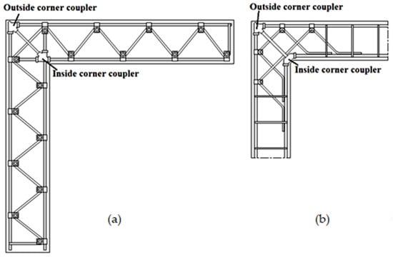
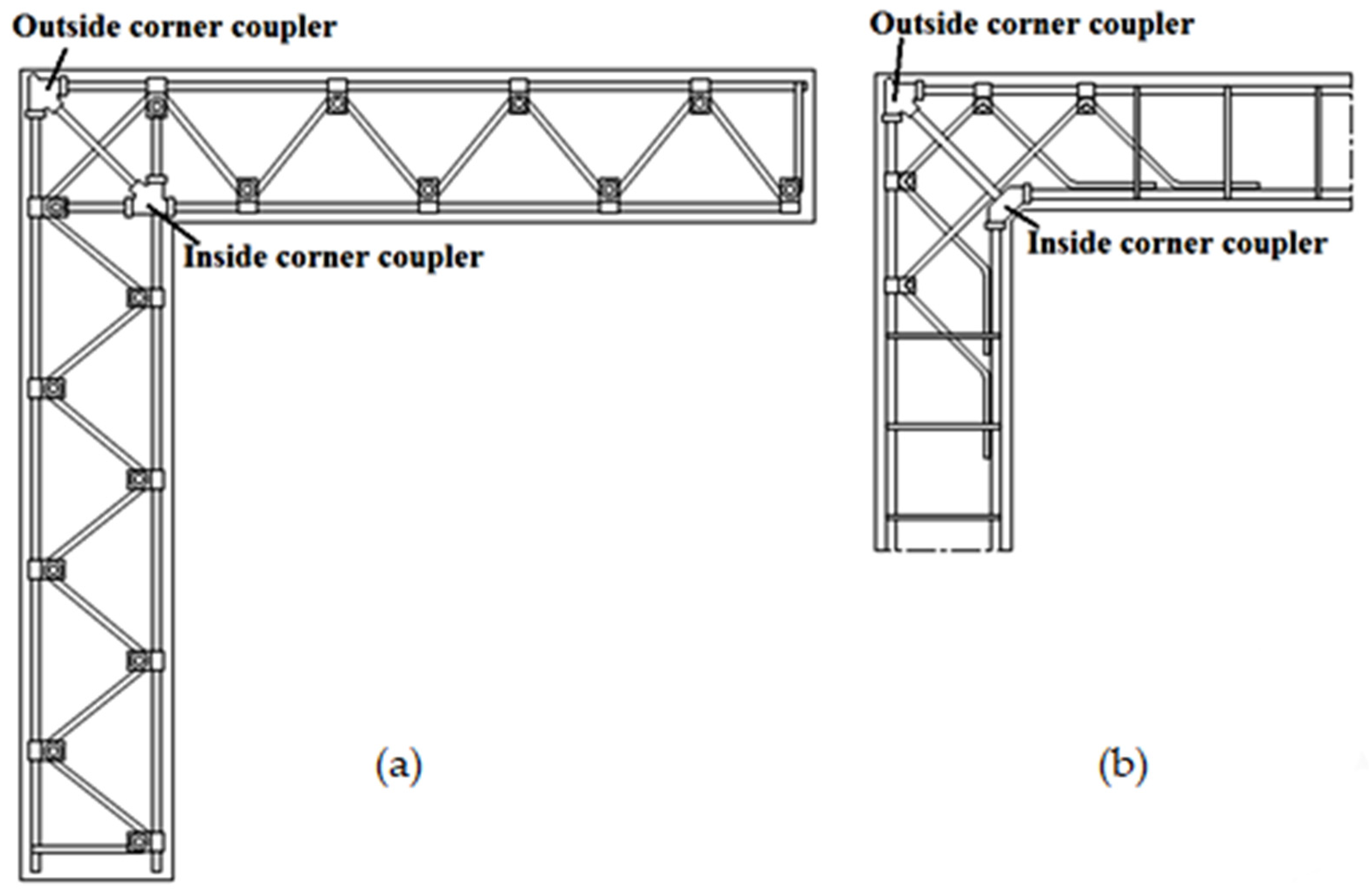
The experimental study conducted by Al-Tuhami et al. [1] showed that, with the use of an L-shaped mechanical coupler instead of bending the main tension reinforcement in the corner joint, it increases the ductility as well as significantly increasing the efficiency, performance, and load-carrying capacity. The results of the present study confirm the importance of both cross diagonals in reinforcing the knee joint for enhancing the overall knee joint behavior. Accordingly, it is suggested that the reinforcement system shown in Figure 16a is compatible with the knee joint, whether exposed to negative and/or positive bending moments. The future of this reinforcement system is that all truss members, including the two diagonals, are connected to the truss joints. Another reinforcement proposal useful with the traditional reinforcement details is given in Figure 16b. This proposed reinforcing system includes the advantages of the truss system in the knee joint with the conventional reinforcement in the adjacent members, which will be cheaper and easier for fabrication.
Figure 16.
Joint reinforcement systems for further study. (a) fully connected truss reinforcement; (b) hybrid truss–conventional reinforcement system.
The current study focuses on evaluating the joint performance under unidirectional closing moments. Further experimental investigations under reversed cyclic loading conditions, representative of seismic actions, are recommended to better assess the behavior of the proposed system. It is expected that the integration of mechanical joints with the truss-shaped reinforcement (Figure 16) may enhance the stability of the load-transfer mechanism and improve energy dissipation capacity under cyclic loading.
7. Conclusions
- 1
- The truss-skeleton system significantly decreased cracking, not just in the knee-joint area but also throughout the beam and column. In contrast, the traditional specimens exhibited a much denser propagation of flexural cracks.
- 2
- In the truss configuration, the specimen (TR) showed significant hardening after yielding, unlike the traditional specimens, thereby enhancing structural safety and providing a clear warning before failure.
- 3
- The proposed specimen achieved noticeable improvements in both yield load and ultimate load compared with the traditional specimens. The yield-load increase ranged from 29.5% to 70.5%, while the ultimate-load increase ranged from 20% to 81%.
- 4
- The suggested specimen a considerably higher displacement capacity, with increases ranging from 88% to 347% compared to the traditional specimens. Additionally, the displacement ductility index saw substantial improvement, increasing by approximately 160% to 382% in relation to the traditional specimens. Moreover, the proposed specimen showed a significant enhancement in stiffness, with an improvement ranging from about 70% to 126% compared to the traditional specimen.
- 5
- The proposed reinforcement system effectively relocated the critical failure area away from the complex stress of the knee joint to the mid-span region of the column. This shift in failure mode maintains joint integrity and aligns with seismic design principles by avoiding brittle failure in the knee joint area.
- 6
- The proposed strut-and-tie model (STM) for conventional specimens and the simplified truss-based model for the TR accurately represented the internal force distributions. Experimental strain readings for the main reinforcement’s tensile forces closely matched theoretical predictions (e.g., 5.16P–6.60P observed compared to 6.38P predicted for traditional specimens, and 2.40P–3.17P observed compared to 2.60P–2.80P predicted for TR). This agreement verifies the accuracy of the analytical models and their efficiency to represent the post-cracking load-transfer mechanism.
- 7
- Analytical predictions for the CTT node and the diagonal strut load capacity of the TR indicated that it could bear loads of about 86.5 kN and 98.8 kN, respectively. Despite this, during experimentation, the specimen failed in the middle section of the column under a peak load of 51.01 kN. This outcome verifies that the proposed truss reinforcement system effectively eliminates the knee joint as the weakest joint.
- 8
- The analytical evaluation showed that the tensile internal force on the main bent reinforcement decreased from 6.38P in conventional specimens to 2.8P in the TR, while the diagonal compressive strut force reduced from 9.02P to 4P. This significant reduction in critical force demands ensures delayed yielding and reduced cracking in the proposed specimen.
- 9
- Both the experimental and analytical models demonstrated that the horizontal and vertical stirrups within the knee joint of specimen R2 did not enhance the diagonal compression strut capacity. In contrast, the proposed system, which includes a hybrid diagonal strut (composed of a diagonal reinforcement member and surrounding concrete) along with the transverse diagonal tension member, proves effective at resisting cracks, even under high loads.
- 10
- The suggested reinforcement system is both safer and simpler to fabricate and install. It can be designed to support its own weight as well as the weight of fresh concrete during casting.
Author Contributions
Conceptualization, Methodology, Validation, Formal Analysis, Investigation, Data Curation, Writing—Original Draft, and Writing—Review and Editing: A.Y.A.-T.; Conceptualization, Methodology, Validation, Formal Analysis, Investigation, Data Curation, Writing—Review and Editing, and Supervision: A.G.; Conceptualization, Methodology, Validation, Investigation, Data Curation, Writing—Review and Editing, and Supervision: S.A.E.-d. All authors have read and agreed to the published version of the manuscript.
Funding
This research received no external funding.
Data Availability Statement
Some or all data that support the findings of this study are available from the corresponding author upon reasonable request.
Conflicts of Interest
The authors declare no conflicts of interest.
Nomenclature
| Maximum tensile strength of the tie | |
| Maximum compressive force of the diagonal strut | |
| Diagonal tension splitting force | |
| Concrete cubic compressive strength | |
| Concrete cylinder compressive strength | |
| Ultimate load obtained from the test | |
| Beam/column cross-section width | |
| Beam/column cross-section height | |
| Beam length | |
| Column length | |
| Center-to-center spacing of mechanical joints (upper or lower chord) or stirrups | |
| Distance from the inner corner to the external load | |
| Yielding load | |
| Ultimate load | |
| Deflection at yielding load | |
| Deflection at ultimate load | |
| Theoretical applied load that causes strut failure | |
| Tensile force in the horizontal and vertical main reinforcement ties | |
| Resultant compressive force derived from the diagonal strut (Fae) and the horizontal strut (Fes) | |
| Internal axial force in the vertical and horizontal compressive struts | |
| Force in the main diagonal compressive strut at knee joint | |
| Resultant compressive force derived from the diagonal strut and the horizontal strut | |
| Maximum allowable compressive strength of the strut or node | |
| Internal axial force | |
| P | Magnitude of the applied external load |
| Bending radius of the main reinforcement bar | |
| Effective width of the diagonal concrete strut | |
| Depth of the equivalent rectangular concrete compression zone | |
| Effective internal lever arm | |
| Cross-sectional area of the diagonal steel reinforcement | |
| Cross-sectional area of the compression steel reinforcement | |
| The angle of inclination between the main diagonal compressive strut and the horizontal tension tie | |
| The angle of inclination between the diagonal compressive strut and the horizontal compressive strut | |
| Angle of the resultant internal compressive force at the inner node | |
| Compression–tension–tension nodal zone | |
| Compression–compression–compression nodal zone |
References
- Al-Tuhami, A.T.; Ghallab, A.; Al-Tuhami, A.Y. Behavior of closing knee joints using L-shaped coupler instead of bending bars. ACI Struct. J. 2021, 118, 153–166. [Google Scholar] [CrossRef] [Scilit]
- Elinder, U.; Hallhagen, B. Spjälkningsrisk vid Bockad Buntad Armering; (Risk of Spalling When Using Bent Bundled Reinforcement Bars); The Royal Institute of Technology: Stockholm, Sweden, 1967. (In Swedish) [Google Scholar]
- Östlund, L. Inverkan av Bockningsradier and Täckande Betongskikt hos Kamstål på Spjälkningsrisken för Armerade Betongkonstruktioner (The Influence of Bending Radius and Concrete Cover for Deformed Bars on the Risk of Splitting Failure in Reinforced Concrete Structures); The Royal Institute of Technology: Stockholm, Sweden, 1963. (In Swedish) [Google Scholar]
- Stroband, J.; Kolpa, J.J. The Behaviour of Reinforced Concrete Column-to-Beam Joints—Part 1: Corners Subjected to Negative Moments; Report 5-83-9; Stevin Laboratory, Delft University of Technology: Delft, The Netherlands, 1983. [Google Scholar]
- Wästlund, G. Om armering av vinkelformade betongkonstruktioner (Reinforcement of angle-shaped concrete structures, in Swedish). Betong 1935, 1, 22–35. [Google Scholar]
- Johansson, M. Structural Behaviour in Concrete Frame Corners of Civil Defence Shelters: Non-Linear Finite Element Analyses and Experiments. Ph.D. Thesis, Chalmers University of Technology, Göteborg, Sweden, 2000. [Google Scholar]
- Mayfield, B.; Kong, F.K.; Bennison, A.; Davies, J.C.D.T. Corner joint details in structural lightweight concrete. ACI J. Proc. 1971, 68, 366–372. [Google Scholar] [CrossRef] [Scilit] [PubMed]
- Plos, M.; Gylltoft, K. Splicing of reinforcement in frame corners: Experimental studies. Nord. Concr. Res. 1994, 14, 103–121. [Google Scholar]
- Swann, R.A. Flexural Strength of Corners of Reinforced Concrete Portal Frames; Technical Report TRA 434; Cement and Concrete Association: London, UK, 1969. [Google Scholar]
- Angelakos, B. The Behavior of Reinforced Concrete Knee Joints under Earthquake Loads. Ph.D. Thesis, University of Toronto, Toronto, ON, Canada, 1999. [Google Scholar]
- Kemp, E.L.; Mukherjee, P.R. Inelastic behaviour of concrete knee-joints. Consult. Eng. 1968, 32, 44–48. [Google Scholar]
- Zouzou, A.; Haldane, D. Detailing reinforced concrete closing corner joints for ductility. Proc. Inst. Civ. Eng. Struct. Build. 1993, 99, 43–48. [Google Scholar] [CrossRef] [Scilit]
- Marchetto, F. Use of Headed Reinforcement Bars in Construction: A Theoretical Approach to Determine the Dimensions of Anchorage Plates and Experimental Tests on Knee Joints Subjected to a Closing Moment. Ph.D. Thesis, Universidad Politécnica de Madrid, Madrid, Spain, 2015. [Google Scholar]
- Wang, Z.; Hu, Y.; Jiang, L.; Zhou, C.; Zhou, S.; Dai, X.; Jiang, L. Effects of Corner Stiffeners and Tensioned Curved End-Plates on Cyclic Behavior of Prefabricated T-Shaped Inclined Joints. J. Build. Eng. 2026, 120, 115535. [Google Scholar] [CrossRef] [Scilit]
- El-Naqeeb, M.H.; Hassanli, R.; Zhuge, Y.; Ma, X.; Bazli, M.; Manalo, A. Beam-column connections in GFRP-RC moment resisting frames: A review of seismic behaviour and key parameters. Structures 2025, 71, 108109. [Google Scholar] [CrossRef] [Scilit]
- Nadir, W.; Ali, A.Y.; Jawdhari, A.; Kadhim, M.M.A. Static behavior of UHPC corner beam–column joint under constant axial and increasing bi-directional bending loads. Int. J. Civ. Eng. 2024, 22, 1291–1308. [Google Scholar] [CrossRef] [Scilit]
- Han, S.W.; Lee, S.H. Cyclic behavior of high-performance fiber-reinforced cementitious composite corner joints. J. Build. Eng. 2022, 47, 103892. [Google Scholar] [CrossRef] [Scilit]
- Zainal, S.M.I.S.; Hejazi, F.; Rashid, R.S.M. Enhancing the performance of knee beam–column joint using hybrid fibers reinforced concrete. Int. J. Concr. Struct. Mater. 2021, 15, 20. [Google Scholar] [CrossRef] [Scilit]
- Lin, G.; Zeng, J.-J.; Liang, S.-D.; Liao, J.-J.; Zhuge, Y. Seismic behavior of novel GFRP bar reinforced concrete beam-column joints internally reinforced with an FRP tube. Eng. Struct. 2022, 273, 115100. [Google Scholar] [CrossRef] [Scilit]
- Nezami, S.A.; Shooshtari, A.; Shafaei, J. Bidirectional seismic retrofitting of corner RC beam-column joints by 3D post-tensioned joint enlargement. Structures, 2026; in press. [CrossRef] [Scilit]
- Li, S.-T.; Zhang, W.-X.; Zhou, Y.-B.; Cai, X.-D.; Liang, Y.-Q.; Yi, W.-J. Bidirectional cyclic loading test and numerical investigation of precast concrete corner joints with slabs. J. Build. Eng. 2025, 115, 114504. [Google Scholar] [CrossRef] [Scilit]
- Tariq, M.; Khan, A.; Shayanfar, J.; Hanif, M.U.; Ullah, A. A regression model for predicting the shear strength of RC knee joint subjected to opening and closing moment. J. Build. Eng. 2021, 41, 102727. [Google Scholar] [CrossRef] [Scilit]
- Tariq, M.; Khan, A.; Ullah, A.; Waseem, M.; Nasir, H.; Jamil, I. Shear strength model for reinforced concrete corner joints based on soft computing techniques. Adv. Civ. Eng. 2022, 2022, 7156691. [Google Scholar] [CrossRef] [Scilit]
- Al-Tuhami, A.Y.; Ghallab, A.; Al-Tuhami, A.T. Effect of utilizing simple mechanical truss joints on the performance of hybrid truss-concrete beams subjected to bending. Structures 2025, 78, 109224. [Google Scholar] [CrossRef] [Scilit]
- Albright, A.; Argentoni, A.; Calvi, P.M. Experimental behavior of interior and exterior steel-concrete composite NPS® beam-column joints. Eng. Struct. 2021, 251, 113589. [Google Scholar] [CrossRef] [Scilit]
- Amadio, C.; Macorini, L.; Sorgon, S.; Suraci, G. A novel hybrid system with RC-encased steel joists. Eur. J. Environ. Civ. Eng. 2011, 15, 1433–1463. [Google Scholar] [CrossRef] [Scilit]
- Colajanni, P.; La Mendola, L.; Monaco, A.; Spinella, N. Cyclic behavior of composite truss beam-to-RC column joints in MRFS. Key Eng. Mater. 2016, 711, 681–689. [Google Scholar] [CrossRef] [Scilit]
- Scotta, R.; Tesser, L. Comportamento di nodi trave-pilastro sismo-resistenti in struttura mista di tipo tralicciato soggetti ad azioni cicliche (Experimental behavior of beam-column joints of steel truss and concrete composite structure subjected to cyclic loads). Progett. Sismica 2011, 3, 47–62. [Google Scholar]
- Tesser, L. Composite Steel Truss and Concrete Beams and Beam-Column Joints for Seismic Resistant Frames: Modelling, Numerical Analysis and Experimental Verifications. Doctoral Thesis, Università degli Studi di Padova, Padova, Italy, 2009. [Google Scholar]
- Monaco, A.; Colajanni, P.; La Mendola, L. The structural behaviour of hybrid steel-trussed concrete beams: A literature review of experimental tests and theoretical models. Structures 2025, 71, 108018. [Google Scholar] [CrossRef] [Scilit]
- ISO 6935-2; Steel for the Reinforcement of Concrete—Part 2: Ribbed Bars. ISO: Geneva, Switzerland, 2019.
- Nilsson, I.H.E.; Losberg, A. Reinforced concrete corners and joints subjected to bending moment. J. Struct. Div. 1976, 102, 1229–1254. [Google Scholar] [CrossRef] [Scilit]
- Wang, H.C. Behavior and Design of Concrete Frame Corners: Strut-and-Tie Method Approach. Ph.D. Thesis, Purdue University, West Lafayette, IN, USA, 2020. [Google Scholar]
- ACI Committee 318. ACI 318-19; Building Code Requirements for Structural Concrete. American Concrete Institute: Farmington Hills, MI, USA, 2019.

Disclaimer/Publisher’s Note: The statements, opinions and data contained in all publications are solely those of the individual author(s) and contributor(s) and not of MDPI and/or the editor(s). MDPI and/or the editor(s) disclaim responsibility for any injury to people or property resulting from any ideas, methods, instructions or products referred to in the content. |
© 2026 by the authors. Licensee MDPI, Basel, Switzerland. This article is an open access article distributed under the terms and conditions of the Creative Commons Attribution (CC BY) license.