Article

Enhanced Wear Resistance of HVOF-Sprayed Cr3C2-25NiCr/NiCr Coatings for Steam Turbine Valve Components: The Role of Vacuum Heat Treatment


1
Key Lab of Advanced Technologies of Materials, Tribology Research Institute, Southwest Jiaotong University, Chengdu 610031, China
2
Dongfang Electric Corporation Dongfang Turbine Co., Ltd., Deyang 618000, China
3
State Key Laboratory of Clean and Efficient Turbomachinery Power Equipment, Deyang 618000, China
4
High Speed Aerodynamics Institute, China Aerodynamics Research and Development Center, Mianyang 621000, China
*
Author to whom correspondence should be addressed.
Appl. Mech. 2026, 7(2), 48; https://doi.org/10.3390/applmech7020048
Submission received: 1 April 2026 / Revised: 9 May 2026 / Accepted: 28 May 2026 / Published: 1 June 2026

Abstract

This study presents the fabrication of a Cr3C2-25NiCr/NiCr coating on Co3W3 steel utilizing high-velocity oxygen fuel (HVOF) spraying. The effects of the vacuum heat treatment process on the microstructures, mechanical properties, and wear mechanisms of the coating were systematically analyzed. The results indicated that the microstructure became denser following heat treatment. During the spraying procedure, decarburization resulted in transformation of the metastable phase structure into a stable one. In comparison to the sprayed coating, there was a 93.8% reduction in porosity. The precipitation of nano-secondary carbides shifted the mechanism of solid-solution strengthening to precipitation strengthening, resulting in a 29.1% increase in microhardness. Meanwhile, the thermal softening effect led to a 114.3% increase in fracture toughness. Wear experiments demonstrated that the friction-induced amorphous structure effectively mitigated stress concentration and inhibited crack initiation. The polycrystalline interface transition region between the nano-secondary carbides and the matrix facilitated the shedding of nano-secondary carbides, forming abrasive particles that generated a rolling effect, which significantly reduced the coefficient of friction. The semi-coherent interface between secondary carbides and NiCr decreased the interfacial energy and enhanced the bonding strength, effectively preventing the shedding of carbides during the wear process. Consequently, a dense microstructure, the type of interface, and high hardness and toughness were critical factors in enhancing its wear resistance.

1. Introduction

Steam turbines play a crucial role as the primary power apparatus in coal-fired, nuclear, and gas-steam combined cycle power plants, contributing approximately 80% of the world’s electricity [1,2]. Valve components, acting as critical elements within the turbine regulation system, are subjected to prolonged exposure to harsh service environments, such as high temperature, high pressure, and wet steam, during operation. The resultant wear and contact fatigue damage stand as the primary failure modes for these components [3,4,5]. Currently, HVOF spraying technology is utilized to apply Cr3C2-NiCr metal-ceramic coatings, which have gained widespread use in enhancing performance and repairing the surfaces of valve components due to their exceptional performance in wear [6,7,8], corrosion [9,10], and oxidation [11,12].
It is widely recognized that the wear behavior of carbide-based thermal spray coatings depends on several factors, such as the substrate material, the spraying process, the carbide content, and the degree of decarburization [13,14,15,16]. The high power input of HVOF is conducive to fully melting nickel-chromium alloy binders; however, this process can also lead to the dissolution, diffusion, and melting of carbides, thereby generating supersaturated solid solutions [17]. Furthermore, the high velocity of particles can minimize the dissolution of carbides into the binder and reduce oxidation. Notably, even under conditions of high-velocity impact, well-melted NiCr binder and carbide dissolution can promote splat spreading and substantially reduce carbide rebound, both of which contribute to reducing carbon loss from the deposited splats. Furthermore, rapid quenching during splat spreading may produce amorphous phases and dissolve carbides into supersaturated solid solutions, which could adversely affect tribological properties. The heat treatment of thermal spray coatings not only offers significant engineering application value and economic benefits but also plays a critical role in modulating microstructural evolution and carbide precipitation behavior. Matthews [18] reported the mechanisms of carbide dissolution, melting, and precipitation in Cr3C2-NiCr coatings following heat treatment. These processes led to the formation of an interface transition zone via molten metal binder diffusion, which substantially enhanced the bonding strength between carbides and the metal binder. Additionally, the precipitation of sub-micron and micron-sized carbides contributed to increased microhardness and improved resistance to particle erosion. Liu et al. [19,20] identified that the type, content, and size of carbides in plasma-sprayed Cr3C2-NiCr coatings, along with the carbide–binder interfacial transition zone, are critical factors for enhancing tribological properties at room temperature. Janka et al. [21] found a temperature-dependent response in heat-treated Cr3C2-NiCr coatings: precipitation strengthening at 600 °C enhanced both hardness and ductility, while carbide coarsening at 800 °C led to a reduction of hardness. They argued that the superior wear performance of the heat-treated Cr3C2-NiCr coating is attributed to three key factors: enhanced binder ductility, precipitation of fine carbides, and improved fracture toughness. High-temperature heat treatment induces recrystallization of the NiCr binder phase and precipitation of secondary carbides [22], which reduces brittle fracture and lowers the coefficient of friction. Additionally, the incorporation of CeO2 mitigates high-temperature softening of the Cr3C2-NiCr coating, thereby improving its hardness and wear resistance [23].
To properly frame the industrial context of this work, it is important to note that besides HVOF-sprayed Cr3C2-NiCr coatings, other materials and repair techniques have been developed for steam turbine valve components. Alternative substrate materials include precipitation-hardening stainless steel 17-4PH and nickel-based superalloy Inconel 718, both of which are widely used in high-temperature valve applications [24,25]. For coating systems, WC-Co coatings offer high hardness and wear resistance but suffer from decarburization and oxidation above 500 °C [26]; CoMoCrSi (Tribaloy) coatings exhibit good high-temperature wear resistance due to Laves phases [27]; and NiCrBSi self-fluxing alloys provide a balance of wear and corrosion resistance [28]. Regarding repair methods, laser cladding provides a metallurgical bond but involves high heat input and dilution [29], and additive manufacturing techniques, such as directed energy deposition (DED), enable near-net-shape repair of complex components. For example, Illana et al. [29] compared the steam oxidation resistance at 600 °C of Inconel 625 coatings deposited by HVOF and laser cladding, while Stavropoulos et al. [30] discussed hybrid subtractive–additive manufacturing processes for high-value metal components. Despite these alternatives, HVOF-sprayed Cr3C2-NiCr coatings remain attractive due to their cost-effectiveness and ability to coat large, complex geometries with minimal thermal input to the substrate.
As mentioned above, heat treatment is an effective method for enhancing the microstructure, facilitating phase transformation, and ultimately modifying the mechanical performance and wear mechanisms of Cr3C2-NiCr coatings. However, the precipitation behavior of carbides, phase-transition mechanisms, interfacial relationships, and associated mechanical properties require further investigation regarding their influence on wear mechanisms. Although the interfacial relationship between Cr3C2 carbides and the NiCr binder phase has been documented in previous studies, a systematic understanding of its evolution under different vacuum heat treatment temperatures and its correlation with wear mechanisms remains limited. This aspect holds substantial practical value and provides critical guidance for the engineering utilization of Cr3C2-25NiCr coatings.
In this study, a Cr3C2-25NiCr/NiCr coating, characterized by a high concentration of carbides and supersaturated metal binder, was fabricated using HVOF. The precipitation of various morphologies and sizes of carbide grains from the binder was induced at different vacuum heat treatment temperatures. The precipitation behavior of the carbides, phase structure, microstructure, and mechanical properties were thoroughly characterized. The wear performance and failure mechanism of the Cr3C2-25NiCr/NiCr coating were systematically revealed.

2. Materials and Methods

2.1. Materials and Spraying Process

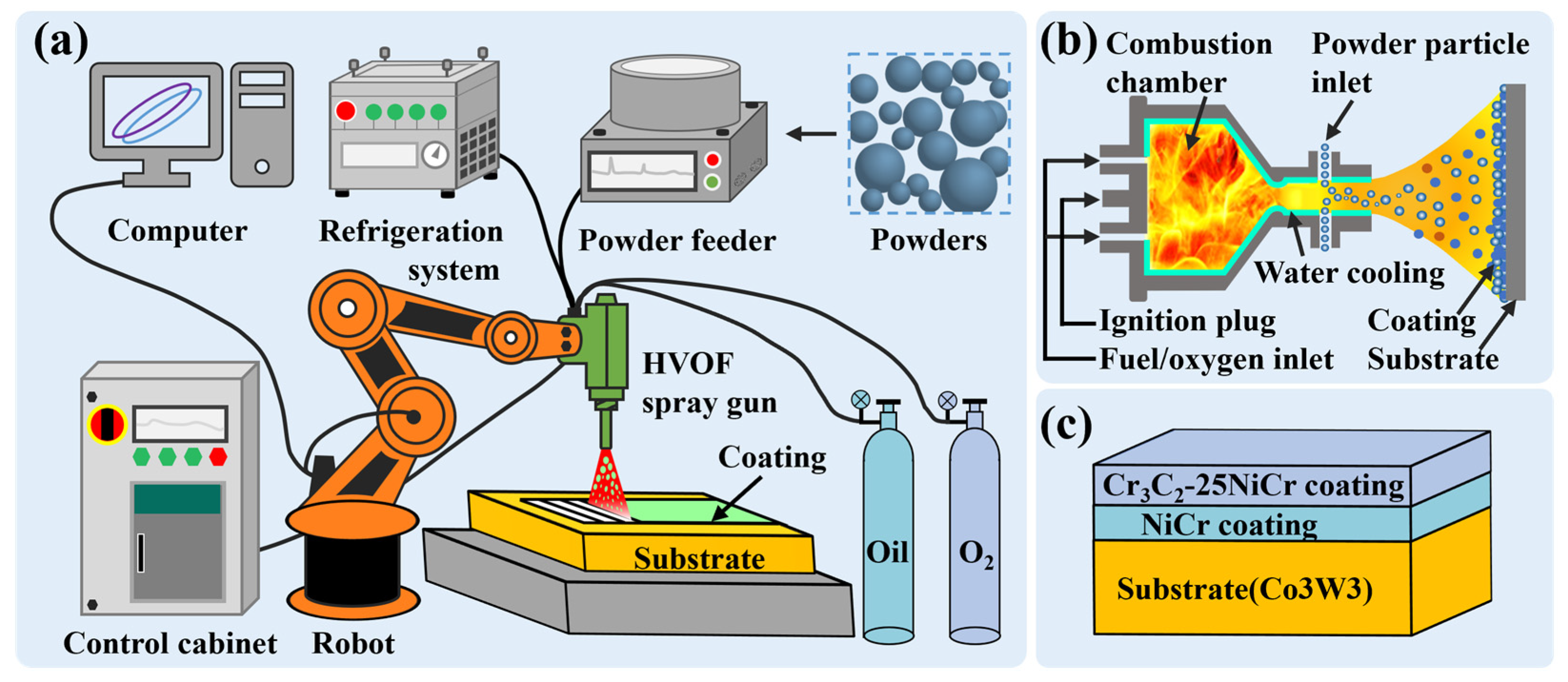
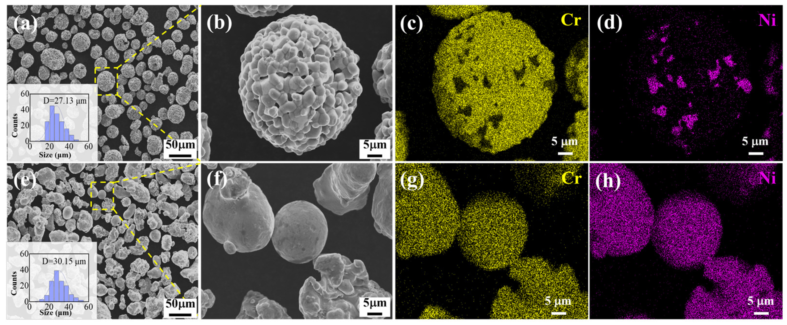
Annealed Co3W3 heat-resisting steel (Panzhan Steel Company, Panzhihua, China) was used as the spray substrate. The chemical composition (wt.%) is presented in Table 1. The specimen was fabricated into a disc with dimensions of Ø25 mm × 5 mm. Prior to spraying, the substrates were ground with SiC abrasive paper (up to 1000 grit) to achieve an average surface roughness (Ra) of 0.3–0.5 µm, then ultrasonically cleaned in acetone and ethanol for 10 min each. The Cr3C2-25NiCr powder and NiCr powder (BGRIMM Advanced Materials Science Technology Co., Ltd., Beijing, China) were prepared using the agglomeration sintering and atomization methods, respectively, and their main chemical compositions (wt.%) were as follows: the Cr3C2-25NiCr powder contained 68.72% Cr, 20.75% Ni, and 10.53% C, while the NiCr powder consisted of 21.7% Cr and 78.3% Ni. Figure 1 displays the SEM results of the two powders. The particle size distribution for both powders was relatively uniform, ranging from 10 to 55 μm, which indicates a high degree of consistency and sphericity. A high-velocity oxygen fuel spraying system (JP-8000TM, Advanced Metallizing Supplies Co., Ltd., Hongkong, China) was utilized to deposit the coating, and its schematic representation is depicted in Figure 2. The specific parameters for the spraying process included: oxygen flow rate of 900 SLPM, kerosene flow rate of 0.33 L/min, air pressure of 0.586 MPa, carrier gas (N2) flow rate of 15 L/min, powder feed rate of 80 g/min, spraying distance of 300 mm, and spray speed between 600 and 800 mm/s. The NiCr bond layer was applied in 8 passes to reach a thickness of 100 ± 10 µm. Subsequently, the Cr3C2-25NiCr topcoat was applied in 12 passes to achieve a thickness of 200–250 µm. Between passes, the substrate temperature was monitored using an optical pyrometer and maintained below 200 °C using compressed air cooling.

2.2. Heat Treatment Processes

The Cr3C2-25NiCr/NiCr coating was heat-treated under vacuum at different temperatures using a vacuum tube furnace (OTF-1200S, Kejing Star Technology Company, Shenzhen, China). The heat treatment was conducted at 400 °C, 600 °C, 800 °C, and 1000 °C under a vacuum of 1 × 10⁻³ Pa, with a heating rate of 5 °C/min and a holding time of 1 h, followed by furnace cooling to room temperature at an average rate of approximately 6 °C/min. The 1 h holding time was selected as a practical, economically feasible industrial condition for post-spray heat treatment of large components; it also allowed systematic comparison of the effect of temperature on the initial stage of microstructural evolution. It is acknowledged, following Matthews and Berger [31], that the transformation toward equilibrium microstructures requires considerably longer times (hours to days, especially at lower temperatures). Therefore, the microstructures reported here represent transient states rather than full equilibrium. The samples were designated as follows: C-0 represents the as-sprayed coating (prior to vacuum heat treatment), while C-1, C-2, C-3, and C-4 correspond to the coating heat-treated at 400 °C, 600 °C, 800 °C, and 1000 °C, respectively.

2.3. Wear Tests

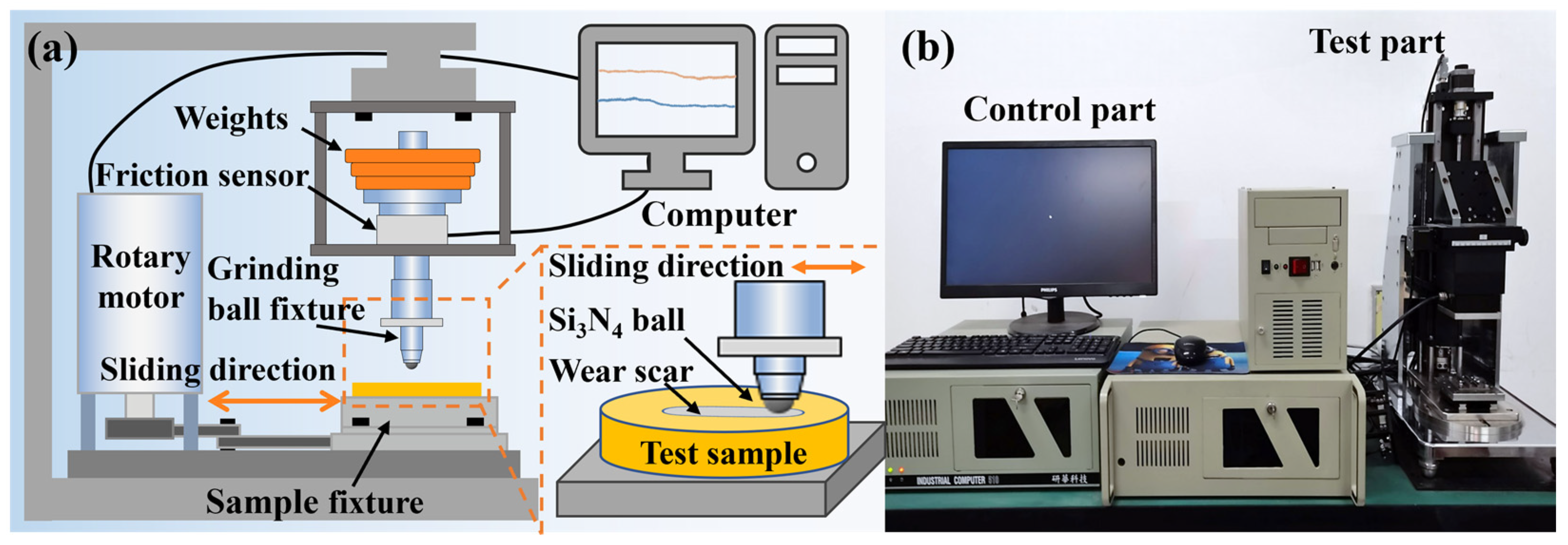
The tribological properties of the coating were evaluated using a reciprocating friction and wear tester (CFT, Zhongke Kaihua Corporation, Lanzhou, China), as depicted in Figure 3. Before the wear tests, all coating samples (as-sprayed and heat-treated) were ground and polished to a uniform initial surface roughness of Ra ≈ 0.2 µm to eliminate the influence of the starting surface conditions on the tribological results. The counterpart was a Si3N4 ceramic ball measuring 6 mm in diameter and possessing a microhardness of 1600–1700 HV1. The use of a high-hardness ceramic ball was chosen to accelerate wear and obtain measurable coating wear rates within a practical test duration. The testing parameters included a load of 50 N, a duration of 30 min, a reciprocating displacement of 5 mm, and a linear speed of 300 cm/min. Calculation of the wear rate (η) was performed according to the following equation:
η = V/NL
where η is the wear rate (mm3/N·m), V denotes the wear volume (mm3), N is the applied load (N), and L signifies the total sliding distance (m). Each sample was tested in triplicate to minimize experimental errors and ensure reliability and consistency.

2.4. Microstructural Characterization

A high-power optical microscope (DM6M, Leica, Wetzlar, Germany) was utilized to examine the microstructure of the coating and to calculate its porosity. The morphology was characterized using scanning electron microscopy (SEM, FEI Quanta 250, Hillsboro, OR, USA) and energy dispersive spectroscopy (EDS, OXFORD X, Ulm, Germany). The phase structure was analyzed through X-ray diffraction (XRD, Rigaku Ultima IV, Akishima, Japan), employing Cu Kα radiation. Additionally, a white-light interferometer (GT-K, Bruker, Karlsruhe, Germany) was employed to characterize the 3D morphology. The electron backscatter diffraction (EBSD, JSM-7900F, Hikari Xp, Akishima, Japan) technique was employed to characterize the crystal orientation and phase composition. Furthermore, high-resolution transmission electron microscopy (TEM, Tecnai G2 F30, Hillsboro, OR, USA) was employed to analyze the microstructure of the wear subsurface. Simultaneously, geometric phase analysis (GPA) was conducted, utilizing the GPA plug-in in DM software to acquire localized microscopic strain data.

2.5. Mechanical Testing

An automated hardness tester (Qness 60A+, ATM, Mammelzen, Germany) was employed to assess microhardness, with the testing parameters set to a 0.3 kg load and a 15 s indentation period. Simultaneously, the Vickers indentation method (5 kg load, 15 s dwell time) was implemented to assess fracture toughness and to examine the characteristics of indentation cracks within the coating section. Fracture toughness was determined using the Evans formula [32]:
K I C = 0.079 P a 3 2 log 4.5 a c
where KIC is the fracture toughness (MPa·m1/2), P is the applied load (N), a is the diagonal length of half indentation (μm), and c is the distance from the center of the indentation to the crack tip (μm). The following inequality must hold: (0.6 ≤ c/a ≤ 4.5). Utilizing this formula, the average value from five data groups was calculated to assess the fracture toughness. The residual stress on the surfaces of the coatings was evaluated using an X-ray diffraction instrument (G.N.R, Milan, Italy) equipped with a Cr-Kα target.

3. Results and Discussion

3.1. Phase Composition

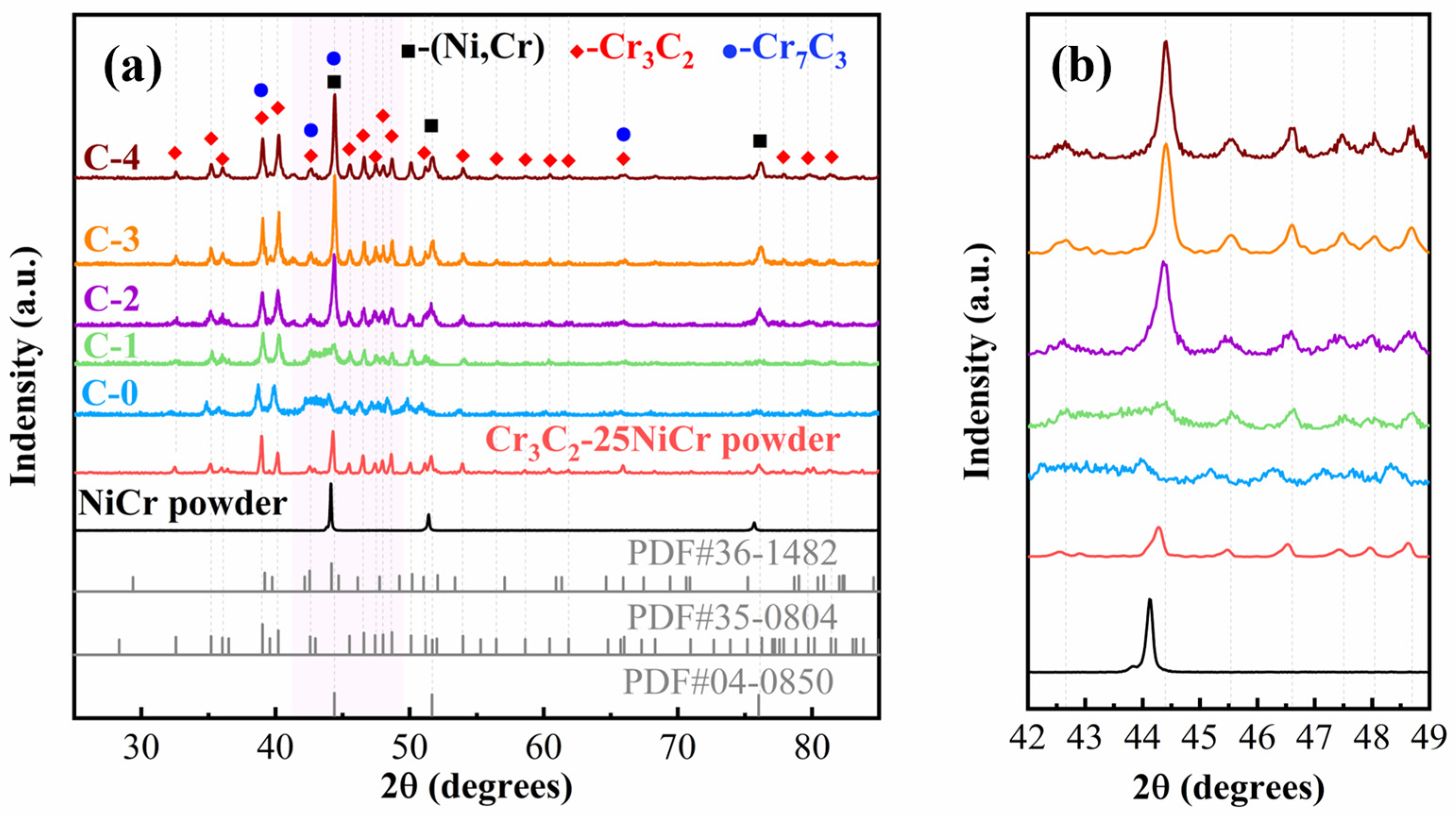
Figure 4 illustrates the XRD patterns of the coating after heat treatment at different temperatures. The results indicate that the sprayed coating (denoted as C-0) primarily comprises the NiCr and Cr3C2 phases, along with a minor presence of the Cr7C3 phase. During the spraying process, high temperatures or oxidation cause decarburization, leading to decomposition of the Cr3C2 phase and formation of the metastable Cr7C3 phase. Moreover, chromium ions within the newly formed Cr7C3 phase can be readily replaced by nickel, resulting in the (Ni,Cr)7C3 phase [31,33]. It is noteworthy that an amorphous hump appears on the left side of the NiCr characteristic peak at 44°. This phenomenon arises during the spraying process when Cr3C2 dissolves in the NiCr binder phase, forming Cr and C-supersaturated amorphous NiCr phases, which leads to the broadening of the NiCr characteristic peak. Furthermore, as the heat treatment temperature increases, no significant changes are observed in the C-1 coating at 400 °C, indicating that low-temperature heat treatment exerts no noticeable influence on the coating. At 600 °C, the amorphous humps disappear, and the diffraction peaks of NiCr and Cr3C2 become sharp. This phenomenon is attributed to the precipitation of carbides dissolved within the NiCr alloy phase, which results in the formation of a significant quantity of high-density, fine secondary Cr3C2 phases. As the temperature continues to rise, no phase transformation occurs in the C-3 and C-4 coatings, indicating that the Cr3C2-25NiCr coating possesses exceptional microstructural stability at high temperatures. Furthermore, at 44° and 76°, the characteristic peak of NiCr increases and becomes sharper with rising temperature, suggesting that the crystallinity of the NiCr grains improves as the temperature increases.

3.2. Microstructure Analysis

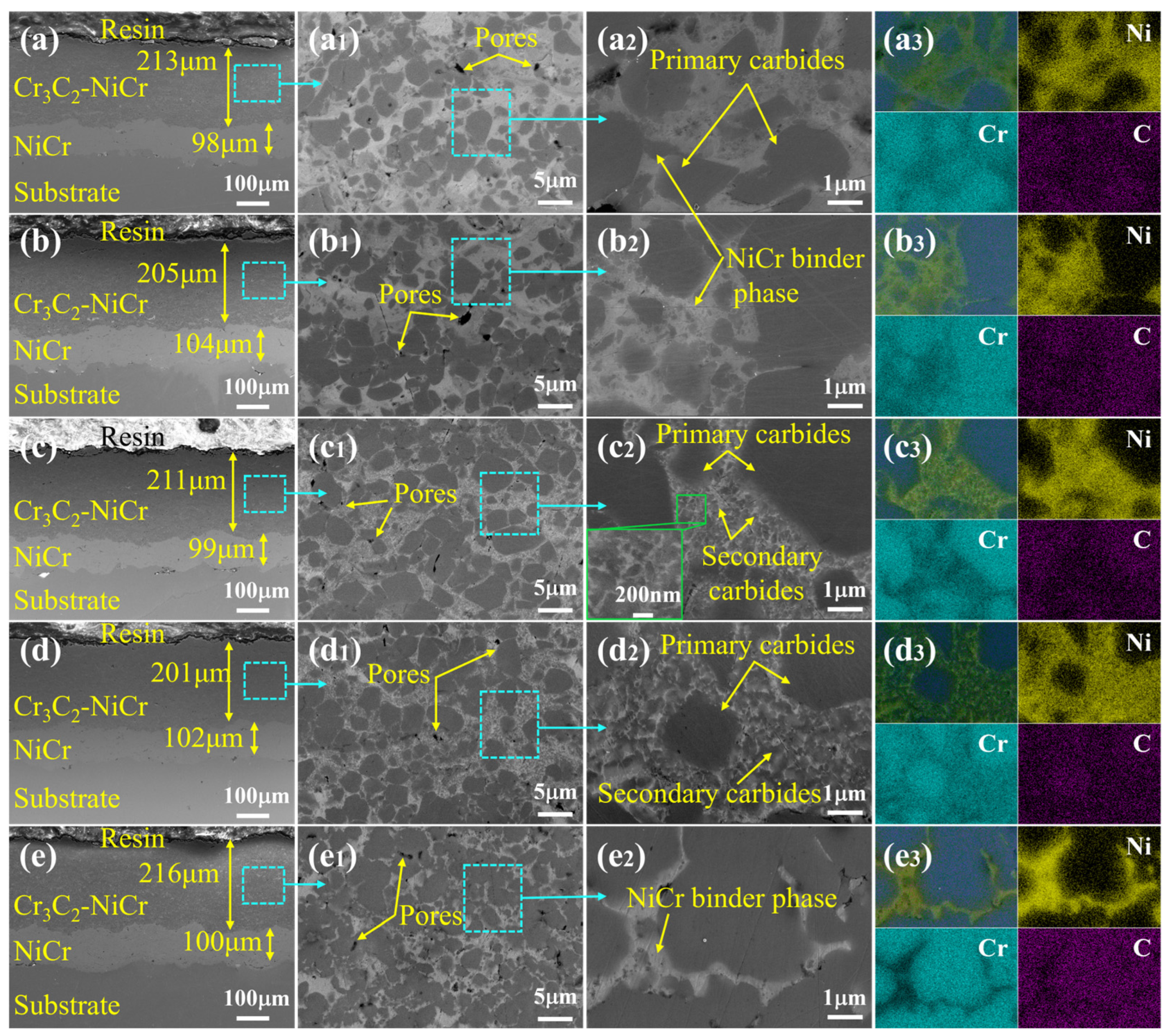
Figure 5 displays SEM images illustrating the microstructural evolution of the coating at various heat treatment temperatures. The Cr3C2-25NiCr coating exhibits a thickness of approximately 210 ± 10 μm, whereas the intermediate NiCr transition layer has a thickness of 100 ± 10 μm. A dense structure is observed in the coating, and no significant cracks or delamination are detected. Figure 5a presents the section of the sprayed C-0 coating. Coupled with the results of EDS analysis, this section is primarily composed of a light white NiCr binder phase and a dark gray primary carbide hard phase. The primary carbide is uniformly distributed within the alloy binder phase in a polygonal shape, resulting in a characteristic “soft matrix + hard phase” structure. With increasing heat treatment temperature, the uniformity of the structure is significantly enhanced. There is no notable difference between the C-1 and C-0 coatings, which aligns with the XRD results. At a temperature of 600 °C, the carbides that dissolved in the NiCr alloy phase precipitate out, resulting in the formation of numerous fine secondary Cr3C2 precipitation reinforcement phases, measuring between 50 and 200 nm, as presented in Figure 5(c2). The microstructure of the C-2 coating exhibits primary carbides, a high density of secondary carbides, and the NiCr binder phase. The secondary carbides precipitate during the recovery and recrystallization of the binder phase, with the Cr present in the NiCr binder phase contributing to the formation of these secondary carbides. Consequently, the metallic matrix is mainly composed of the element Ni [34,35]. As the temperature continues to rise, the size of the secondary carbides in the C-3 coating increases significantly. Matthews et al. [36,37] indicated that the hard phase of the secondary carbides, which is in solid solution within the NiCr alloy, precipitates under the influence of thermal energy. This process is accompanied by Ostwald ripening, which occurs with increasing temperature and time, leading to the growth of these hard-phase particles. Additionally, the primary and secondary carbides aggregate, as shown in Figure 5(d2,e2).
To further examine the microstructural evolution of the coating during heat treatment, inverse pole figure (IPF) plots were analyzed. Figure 6a–e presents the IPF diagram of the Cr3C2-25NiCr coating subjected to various heat treatment temperatures, with distinct colors indicating different crystal orientations. During the spraying process, molten powder particles impact the substrate surface at high velocity, leading to significant plastic deformation of the Cr3C2-25NiCr coating, which creates defects and induces internal stresses [38]. Consequently, the orientation of each grain is not entirely consistent, and no distinct preferred orientation is observed. Grain size constitutes one of the critical factors influencing material properties [39,40,41]. The bar chart presented in Figure 6(a1,b1,c1,d1,e1) illustrates the results of grain size statistics for the C-0, C-1, C-2, C-3, and C-4 coating samples. The average grain diameters for these samples are 0.44 μm, 0.48 μm, 0.46 μm, 0.55 μm, and 0.66 μm, respectively. As the heat treatment temperature increases, the grain size of the coating exhibits a gradual increase. Notably, at a temperature of 600 °C, a smaller grain size is observed in the C-2 coating than in the C-1 coating. Additionally, the results from the 3D pie chart indicate that the majority of the grains in the coating consist of nanometer or submicron grains (less than 1 μm).
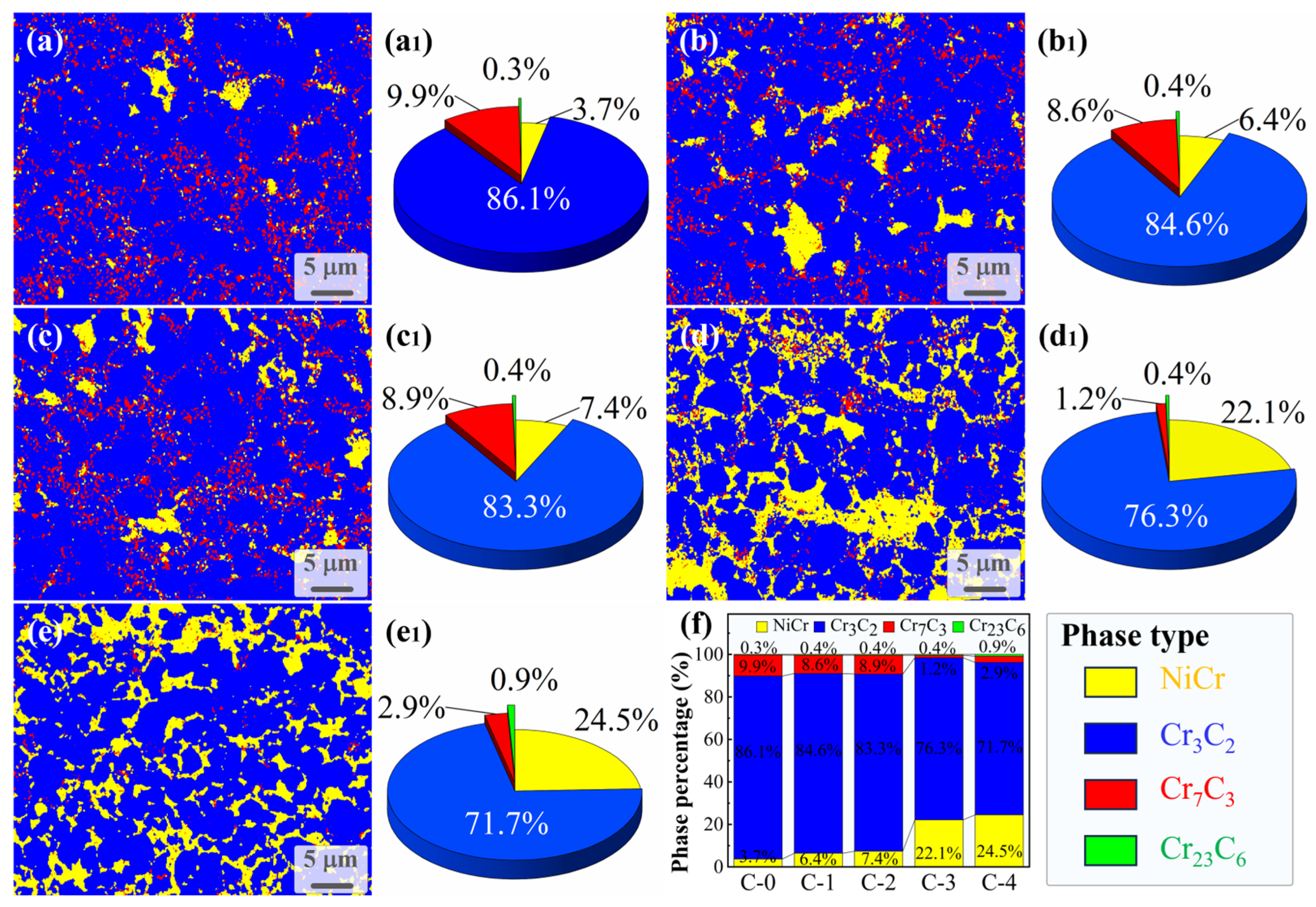
The results of the EBSD phase diagram analysis for the coating samples subjected to various heat treatments are presented in Figure 7. All coating samples consist of the NiCr phase, Cr3C2 phase, Cr7C3 phase, and a minor amount of the Cr23C6 phase, with these findings corroborated by XRD analysis. During the spraying process, certain carbides dissolve, resulting in a supersaturated, metastable, partial amorphous phase structure enriched with chromium (Cr) and carbon (C) elements following rapid solidification of molten alloy particles. The percentage compositions of the NiCr, Cr3C2, and Cr7C3 phases in the C-0 coating are 3.7%, 86.1%, and 9.9%, respectively. As the heat treatment temperature increases, the heat input enhances the solubility of carbon within the nickel lattice and facilitates the precipitation of secondary carbides from the binder phase. In the C-2 coating, the percentage compositions of the NiCr, Cr3C2, and Cr7C3 phases are 7.4%, 83.3%, and 8.9%, respectively (see Figure 7c). As the temperature continues to rise, the metastable alloy phase undergoes significant recrystallization and grain growth, leading to an increase in the NiCr phase content, as illustrated in Figure 7d,e. Meanwhile, the metastable Cr7C3 phase is more likely to transition to the stable Cr3C2 phase, driven by thermal energy. Consequently, the content of the NiCr phase in samples C-3 and C-4 increases to 22.1% and 24.5%, respectively, while the percentage of the Cr3C2 phase decreases to 76.3% and 71.7%, respectively.

3.3. Porosity and Surface Roughness

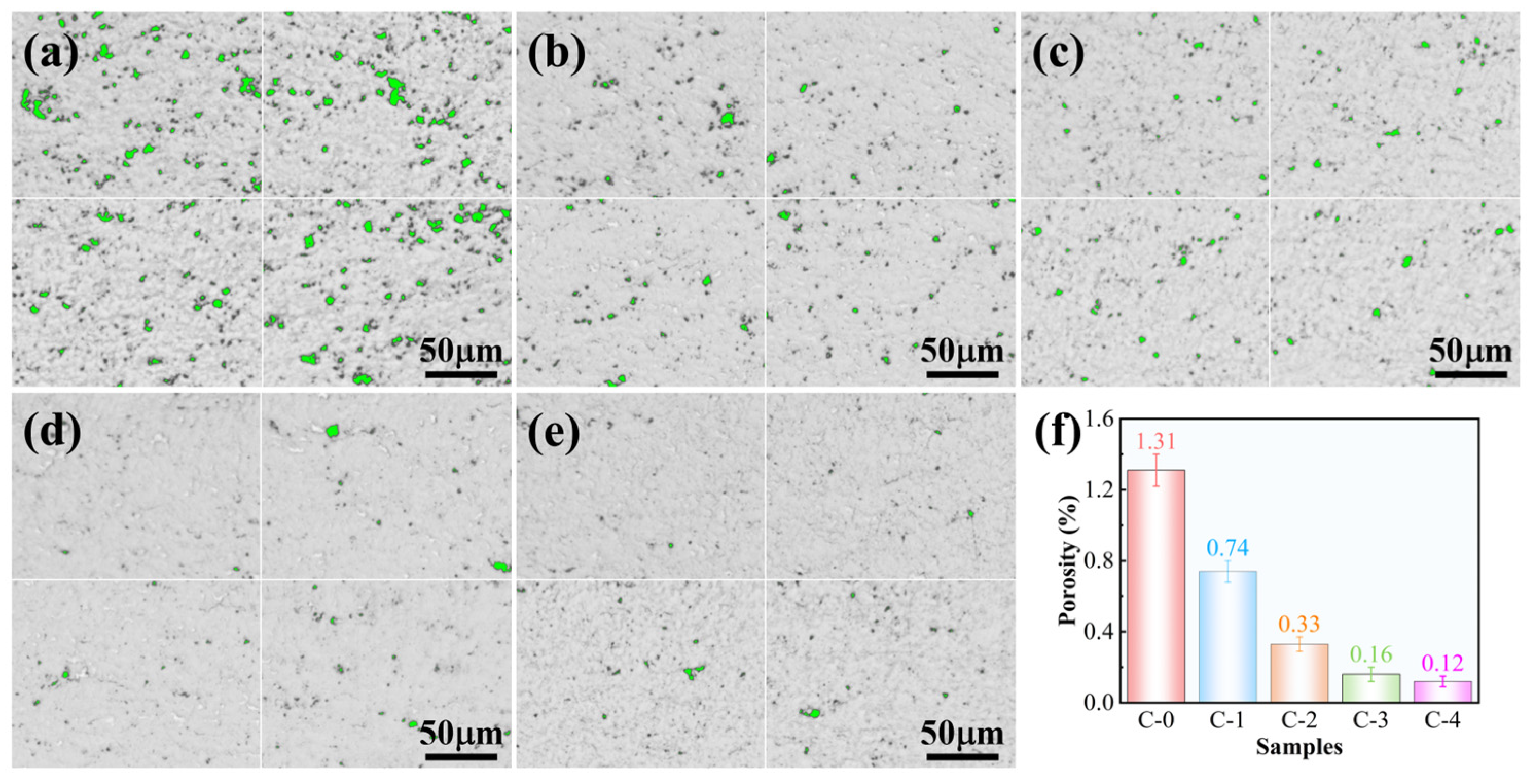
The service performance of a coating depends critically on its porosity level [42,43,44]. Figure 8 illustrates the statistical results of the cross-sectional morphology and porosity of the coating subjected to different heat treatment temperatures. Porosity was measured in optical microscopy cross-sections using an industry-certified standard threshold, with more than four random fields analyzed per sample. The findings indicate that the coating porosity progressively declines as the heat treatment temperature increases. In comparison to the C-0 coating, the porosity of the C-1, C-2, C-3, and C-4 coatings decreases by 39.3%, 73.2%, 91.9%, and 93.8%, respectively. The formation of pores primarily results from inadequate contact between the carbides and the binder phase, as well as the suction effect induced by the high-speed spraying process [45]. This suction effect prevents the complete release of gas during the short solidification period, leading to the entrapment of gas within the coating as pores, which are predominantly located at the interface of the layered structure and the unmelted regions. Heat treatment significantly alters the layered structure and enhances the uniformity of the distribution between the soft matrix and hard-phase structures, while also facilitating sintering [46,47]. Furthermore, it improves cohesion between the hard phase and the binder phase, reduces shedding of the hard phase, decreases porosity, and increases the density of the coating.
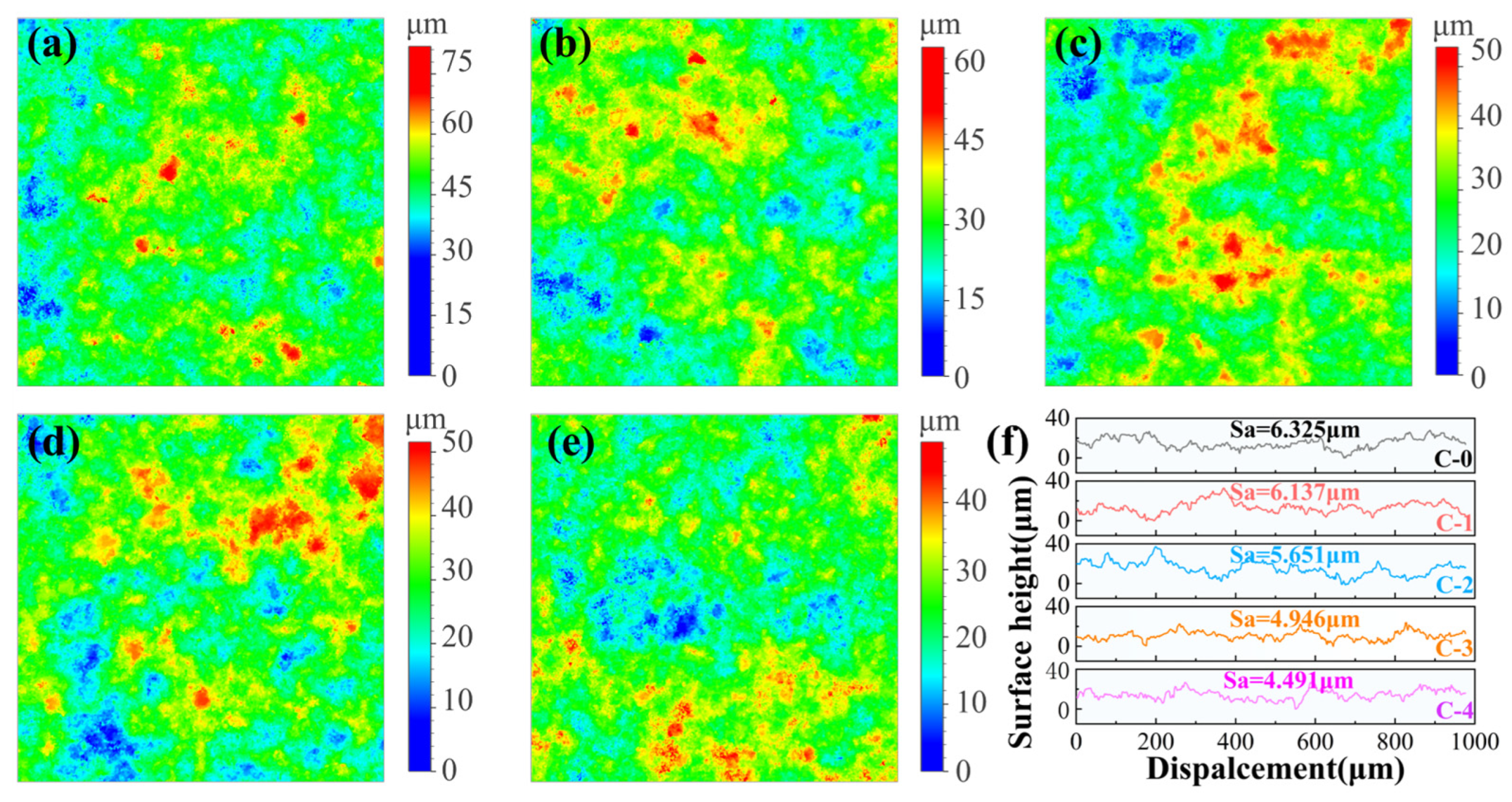
Figure 9 displays the surface roughness and height of the coating after undergoing various heat treatment temperatures, with values measured at 6.325 μm (C-0), 6.137 μm (C-1), 5.651 μm (C-2), 4.946 μm (C-3), and 4.491 μm (C-4), respectively. The overall surface roughness of the coating is notably high, which is primarily attributed to the spraying process. However, it is evident that as the heat treatment temperature increases, surface roughness tends to decrease. Notably, when heat-treated at 1000 °C, the coating exhibits the lowest roughness value.

3.4. Microhardness and Surface Residual Stress

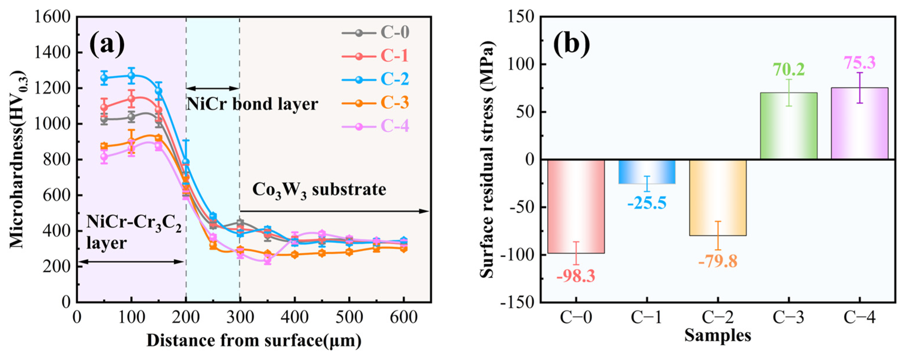
The wear behavior of a coating is significantly influenced by its microhardness and residual stress [48,49,50]. Consequently, we measured the microhardness and residual stress values of the coating following spraying and heat treatment, as displayed in Figure 10. The microhardness distribution curve in Figure 10a indicates that the microhardness of the coating material experiences considerable fluctuations, whereas the microhardness of the substrate remains relatively stable, consistently approximating 350 ± 16 HV0.3. This discrepancy can be attributed to the inherent hardness difference between the carbide hard particles and the metal binder phase. As the heat treatment temperature increases, the microhardness of the coating initially rises and then subsequently declines. The increased hardness of the C-1 coating at the lower temperature (400 °C) can be attributed to the homogenization of the coating’s microstructure, resulting from a reduction in coating porosity [51]. The C-2 coating exhibits the highest microhardness, measuring 1246 ± 39 HV0.3. Driven by the high thermal energy, the secondary carbides dissolved in the NiCr alloy phase begin to precipitate, leading to a gradual transition of the coating structure from solid-solution strengthening to precipitation strengthening. It has been reported that when the size of the secondary carbides ranges from 10 to 50 nm, they significantly enhance the precipitation-strengthening effect [52]. As the heat treatment temperature continues to rise, the precipitated phase aggregates and grows into primary hard-phase particles. According to Oroman’s strengthening theory [53], an increase in the particle size of the precipitated phase results in a decrease in the number of dispersed particles, an increase in spacing, a reduction in dislocation movement resistance, and a consequent decrease in material strength. Concurrently, the growth of NiCr grains causes the matrix to soften, leading to a reduction in the average microhardness of the coating. Furthermore, the hardness is also influenced by porosity: a high porosity level makes the coating susceptible to collapse under external forces, resulting in larger indentation and reduced hardness. Figure 10b presents the analysis of surface residual stress. The C-0 coating demonstrates a compressive residual stress of −98.3 ± 8 MPa, caused by the continuous high-velocity impact of powders during the spraying process. This impact induces plastic deformation and a shot peening effect on both the substrate and the deposited coating, thereby producing the residual compressive stress. A low-temperature (400 °C) heat treatment facilitates the release of this residual compressive stress, resulting in a reduced value of −25.5 ± 8 MPa. By contrast, at a temperature of 600 °C, the residual compressive stress increases, potentially due to the precipitation of secondary carbides. Furthermore, when the temperature reaches 800 °C, the residual compressive stress transitions to tensile stress.

3.5. Indentation Fracture Toughness

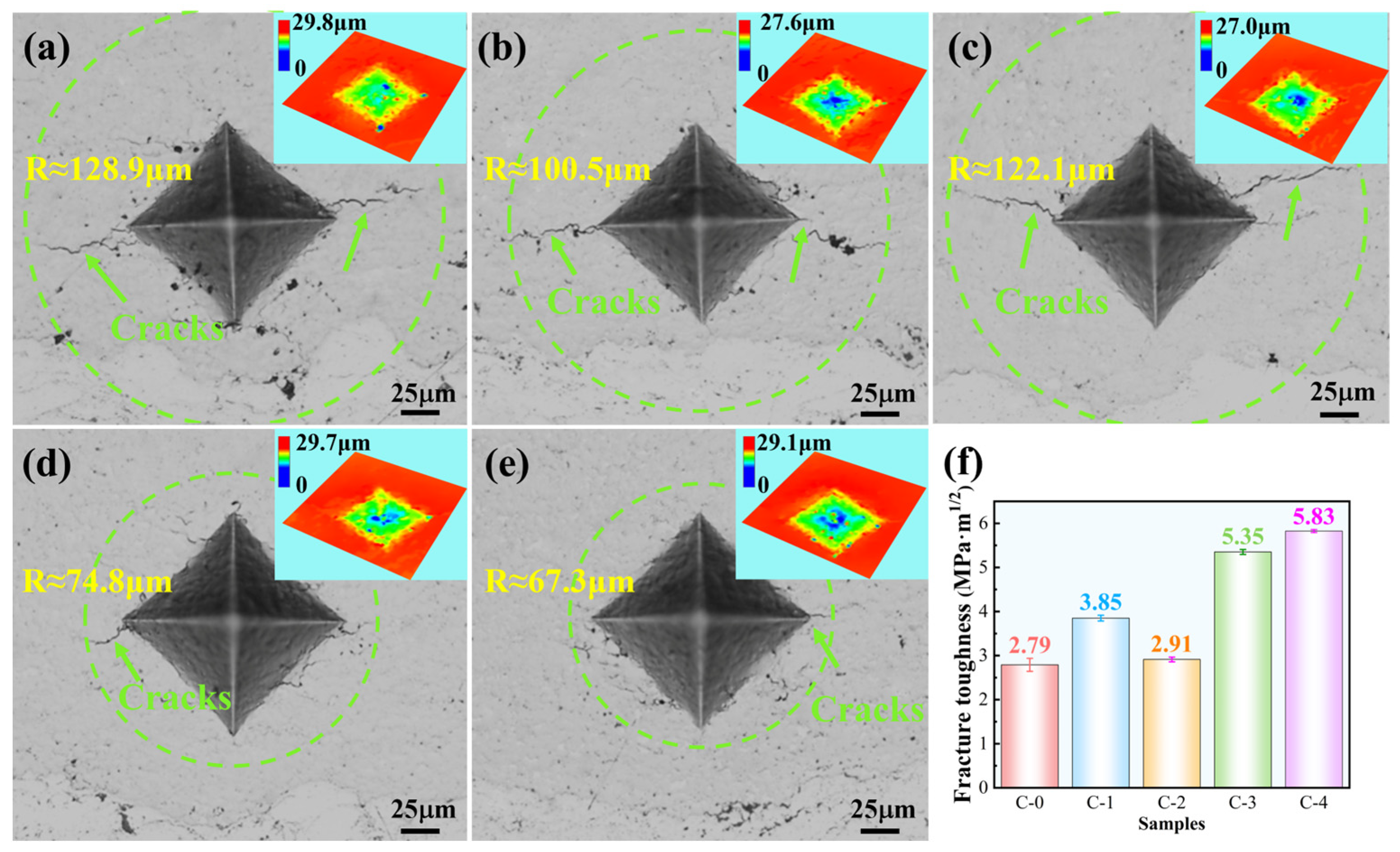
Figure 11 illustrates the indentation crack growth morphology of the coating. Under an applied load, the coating relieves stress by generating cracks [54]. It is observed that all cracks propagate parallel to the interface direction, with no perpendicular cracks observed. First, the compressive stress generated by the shot peening effect during the spraying process effectively inhibits crack propagation in the direction perpendicular to the interface [55]. Second, for coatings characterized by a layered structure, the interlayer interfaces tend to localize stress, acting as a concentration point for stress [56]. Consequently, cracks propagate parallel to the interface from the top corner of the indentation quadrangular cone. Figure 11f shows the variation in fracture toughness with heat treatment temperature, revealing a positive correlation between the two. Specifically, heat treatment facilitates the alleviation of residual stress, reduces porosity and other defects, enhances microstructural uniformity, and suppresses crack propagation. Furthermore, the growth of NiCr grains leads to matrix softening, which contributes to increased toughness. According to the crack propagation laws pertinent to thermal-sprayed, metal-based ceramic coatings [57], micro-cracks emerge under specific compressive stresses, with cracks predominantly propagating along the binder phase and deflecting when encountering hard-phase particles. Consequently, the enhanced toughness of the binder phase following heat treatment has a certain inhibition effect on crack propagation. It is noteworthy that the fracture toughness of the C-2 coating decreased slightly. The results from EBSD and XRD indicate that heat treatment at 600 °C promotes the precipitation of a considerable amount of secondary Cr3C2 hard phase from the NiCr alloy phase. This process leads to a transformation in the coating structure from solid-solution strengthening to precipitation strengthening, thereby optimizing the strengthening effect. Consequently, while the microhardness of the coating increases, the fracture toughness experiences a decline.

3.6. Tribological Properties

3.6.1. Coefficient of Friction and Wear Rate

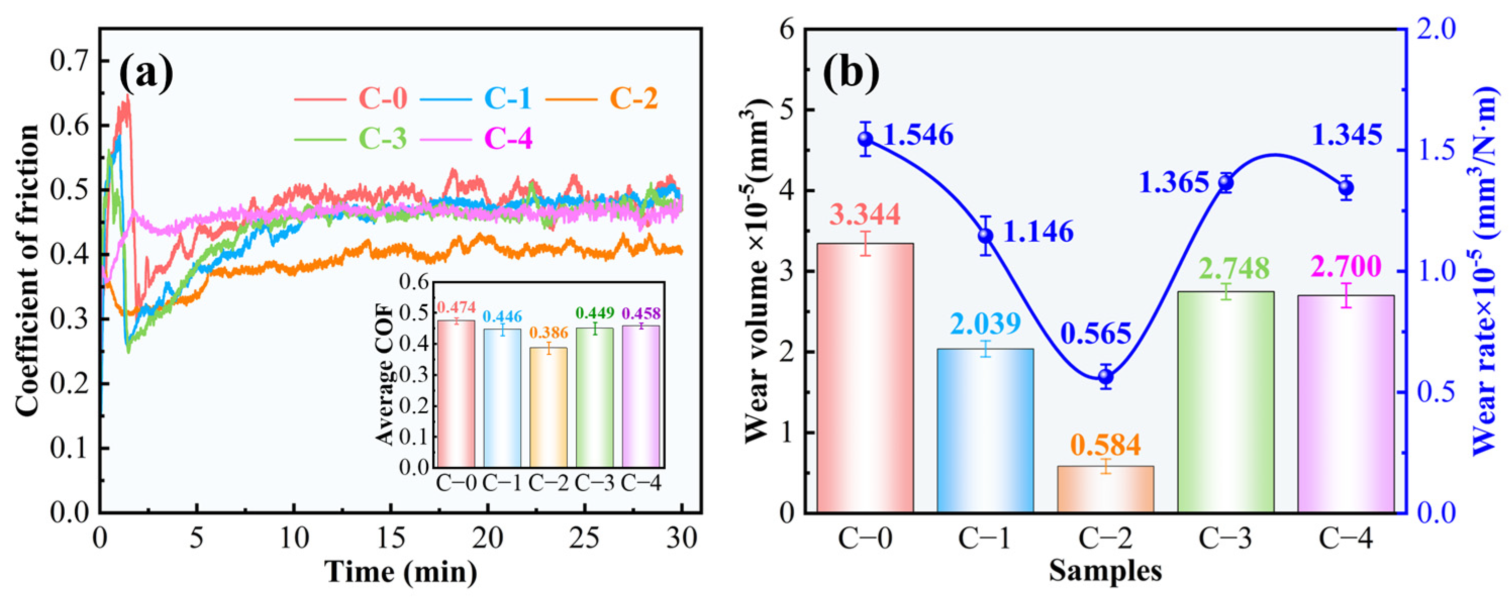
Figure 12 presents the wear results of the Cr3C2-25NiCr coating. The wear behaviors of the five coatings can be categorized into two distinct stages: the initial contact wear stage and the stable wear stage, as illustrated in Figure 12a. The COF is influenced by several factors, including the hardness, the surface morphology, and the contact arrangement between the coating and the frictional pair [58]. During the initial contact wear stage, the COF of the coating surface in contact with the Si3N4 ball exhibits significant fluctuations and an abrupt increase. A substantial number of carbide hard particles within the coating are prone to falling off during wear, while the uneven internal structure of the coating contributes to the fluctuations observed in the COF curve. As the wear time increases, the contact area between the Si3N4 ball and the coating surface expands, leading to a gradual stabilization of the COF. This observation proves that it has entered the stable wear stage. Notably, heat treatment shortens the time needed for the COF to reach this stable wear stage and lowers the average COF in comparison to the C-0 coating. Figure 12b illustrates the wear rate and volume for all coatings. Initially, both the wear rate and volume exhibit a decrease with increasing heat treatment temperature, followed by an increase. The C-0 coating demonstrates the highest wear volume (3.344 × 10⁻⁵ ± 0.15 mm3) and wear rate (1.546 × 10⁻⁵ ± 0.07 mm3/N·m), suggesting that heat treatment enhances the wear resistance of the Cr3C2-25NiCr coating. By contrast, the C-2 coating exhibits the lowest wear volume (0.584 × 10⁻⁵ ± 0.09 mm3) and wear rate (0.565 × 10⁻⁵ ± 0.05 mm3/N·m), suggesting that it possesses the best wear resistance among the samples. According to Achard’s law [59], the hardness of a coating is directly related to its wear rate, specifically, greater hardness correlates with a lower wear rate. However, while the hardness of the C-0 coating exceeds that of the C-3 and C-4 coatings, its wear rate is also higher, suggesting that its wear resistance is comparatively inferior. This indicates that, in addition to hardness, other factors also influence the wear performance of the coating.

3.6.2. Wear Surface 3D Morphology

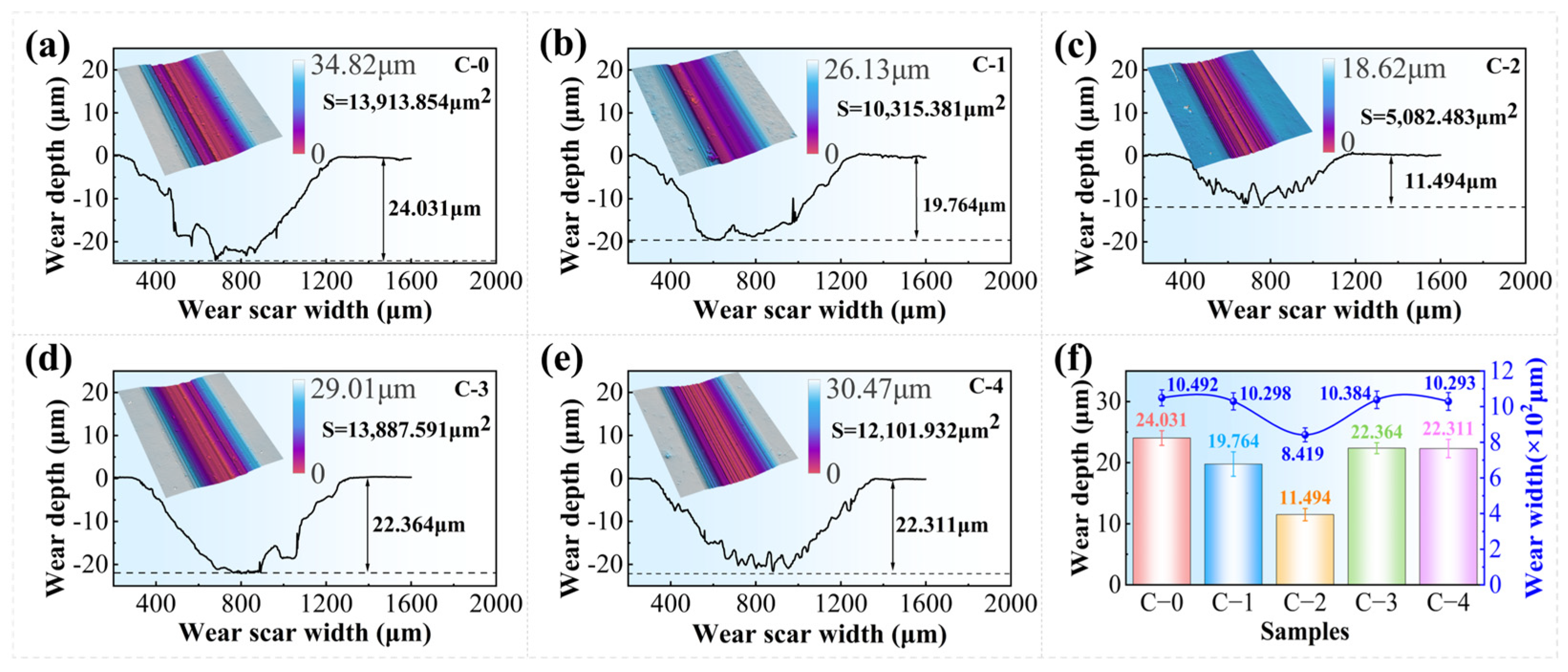
Figure 13a–e illustrates the 3D morphology and wear profiles of the coating, including measurements of the width and depth of wear. The findings indicate that wear depth and area initially decrease before subsequently increasing with a rise in heat treatment temperature. The C-2 coating exhibits the lowest wear depth and width, signifying superior wear resistance, which corresponds with the wear rate results. Additionally, the wear scar and profile of the C-0 coating present a rough appearance, characterized by prominent bumps and pits on the wear surface, which are the typical results of extensive spalling and delamination. By contrast, following heat treatment, the wear profile transitions to a smoother or zigzag form, signifying a shift in the coating’s wear mechanism. This alteration may be attributed to changes in microstructure, hardness, fracture toughness, and residual stress resulting from the heat treatment process.

3.6.3. Wear Surface Failure Mode

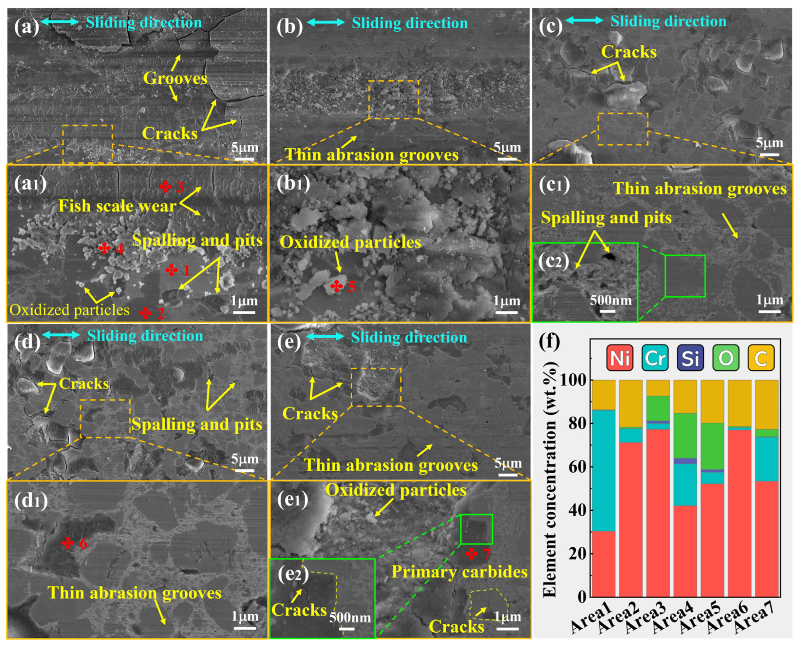
To analyze the wear process and mechanism of the coating, the surface wear morphology was examined by SEM. Figure 14a depicts the wear track of the C-0 coating. Notable cracks, grooves, delamination, and spalling pits are observed, which are characteristic of brittle fracture phenomena. This indicates that the coating predominantly undergoes fracture rather than dissipating energy through plastic deformation during wear. In Figure 14(a1), the brittle fracture of the C-0 coating causes the primary carbides to fall off and form spalling pits, while the shed hard phase forms grooves on the wear surface, functioning as abrasives—reflecting the abrasive wear mechanism. Furthermore, the shedding and aggregation of a significant number of abrasive particles can result in fish-scale wear. The surface roughness caused by fish scale wear increases friction, resulting in a high COF [60]. The brittle fracture of the C-0 coating is caused by the decomposition of Cr3C2 carbides, which produces a significant amount of C and Cr elements within the coating, resulting in the formation of an oversaturated, metastable solution-strengthening phase of the binder phase, which is in a state of poor toughness and easily fractures [61,62]. Although the high hardness of the hard phase enhances wear resistance, it simultaneously reduces the coating’s overall toughness, rendering it susceptible to brittle fracture under stress. Additionally, higher porosity reduces the interfacial bonding strength between the hard phase and the binder and accelerates the abrasive wear process [63]. The EDS data presented in Figure 14f reveal O and Si elements on the worn surface of the C-0 coating, providing evidence for both oxidative and adhesive wear.
In comparison to the C-0 coating, the wear surfaces exhibit a smoother and shallower profile following heat treatment, with a notable reduction in spalling and cracking. Figure 14b depicts the surface wear morphology of the C-1 coating, where minor parallel furrows and small spalling pits are distinctly observable. The wear surface is populated by numerous oxide particles and debris, with oxidative wear identified as the predominant wear mechanism, accompanied by minor abrasive and adhesive wear. The C-2 coating is overall smooth, although some cracks and abrasive debris are present. Under shear stress, the cracks propagate and form closed rings, ultimately resulting in spalling. Notably, the cracks surrounding these spalling pits extend along the interface of primary carbide and binder phase, as seen in Figure 14(c1). Heat treatment reduces the porosity of the coating and enhances cohesion. This process inhibits both the initiation and propagation of cracks and decreases wear-induced spalling. Concurrently, the increase in overall hardness contributes to enhanced wear resistance. Furthermore, a stress field exists at the interface between numerous precipitated nanoscale secondary carbides and the binder phase, which effectively hinders dislocation slip. As dislocations traverse the nanoscale secondary carbides, atomic mismatches on the slip surface result in increased sliding resistance [64,65]. Furthermore, the interfacial energy between the primary carbides and the binder phase may exceed that between the nano-secondary carbides and the binder phase. Consequently, cracks tend to propagate preferentially along the interface between the primary carbides and the binder phase. Another typical feature of the C-2 coating is the formation of numerous small spalling pits, indicating that a substantial quantity of nano-secondary carbides are shed during wear. Figure 14(c2) presents a representative image of carbide shedding. Research suggests that the nanoparticles shed during wear may function as abrasive particles, contributing to a rolling effect [66], which could explain the significant reduction in the COF of the C-2 coating. Furthermore, the overall hardness and toughness of the binder-phase matrix are enhanced, enabling it to effectively resist wear and absorb energy through plastic deformation, while the brittle primary carbides fracture and disband under cyclic loading. Consequently, the superior wear performance of the C-2 coating is attributed to the altered wear mechanism induced by the precipitation of nano-secondary carbides. As the heat treatment temperature increases to 800 °C and 1000 °C, the wear morphology of the C-3 and C-4 coatings become markedly similar. In addition to some obvious cracks on the worn surface, the number of spalling pits is significantly reduced, and the traces of plastic deformation are evident, as shown in Figure 14d,e. This substantial transformation may be attributed to the thermal softening effect, which reduces the brittleness of the coatings and enhances cohesion. However, the reduction in the overall microhardness of the C-3 and C-4 coatings primarily accounts for their diminished wear resistance, while the increased fracture toughness and decreased porosity positively influence wear resistance.

3.6.4. Wear Subsurface Analysis

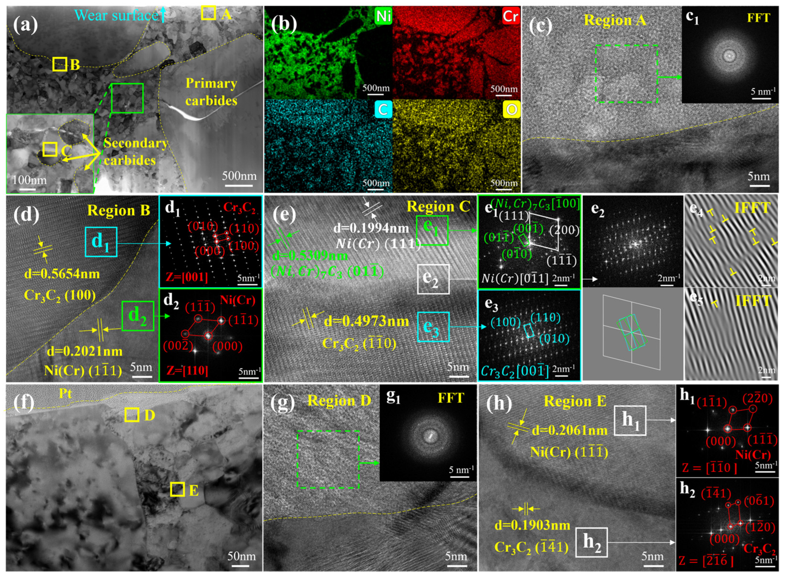
To further investigate the role of primary carbides, nano-secondary carbides, and submicron secondary carbides in the wear process, the FIB technique was utilized to fabricate TEM specimens from the C-2 and C-4 coatings in the wear zone. This method facilitated the analysis of the subsurface microstructure and the interface between the carbides and the NiCr binder phase. Figure 15a,b presents high-resolution transmitted bright-field images of the C-2 coating along with the EDS spectrum results. The morphologies and distributions of the primary carbides and nano-secondary carbides are distinctly observable. An amorphous layer measuring 10–20 nm in thickness is identified on the worn surface. The fast Fourier transform of this layer yields a halo ring, indicative of a friction-induced transition from a crystalline to amorphous structure, as demonstrated in Figure 15(c1). This friction-induced amorphous structure enhances the coating’s strength and wear resistance by generating an attractive force on nearby dislocations, effectively dragging them to the interface and absorbing them. This process alleviates stress concentration and inhibits the formation of micro-cracks [67]. Figure 15d,e shows high-resolution TEM images illustrating the interface structure representative of the primary carbides, nano-secondary carbides, and binder-phase matrix in the C-2 coating. The presence of the Cr3C2 phase and the face-centered cubic Ni(Cr) phase, characterized by an orthogonal structure, is confirmed through the SAED results, as depicted in Figure 15(d1,d2). The crystal face spacings for (100)Cr3C2 and (11-1)Ni(Cr) are measured at 0.5654 nm and 0.2021 nm, respectively. It is evident that the differing crystal structures and lattice parameters result in completely non-coherent interfaces. Figure 15e illustrates the interface structure between the nano-secondary carbides and the NiCr phase. The three regions (Figure 15(e1–e3)) were analyzed using fast Fourier transform, and the corresponding diffraction spots were identified. The interface between the nano-secondary carbides and NiCr is characterized by a polycrystalline transition region composed of the (Ni, Cr)7C3 phase and Ni metastable phase. The results of this study are in line with those previously published by Liu et al. [68].
Figure 15f–h present TEM images of the C-4 coating. Figure 15g also reveals an amorphous layer on the C-4 coating’s wear surface. Furthermore, a distinct interface exists between the secondary carbides and the NiCr binder phase, with crystal face spacings of 0.2061 nm and 0.1903 nm observed at (1-1-1)Ni(Cr) and (-1-41) Cr3C2, respectively. Notably, compared to the C-2 coating, increasing the heat treatment temperature significantly decreases the crystal face spacing of the Cr3C2 phase, while the matrix transitions from a polycrystalline interface transition region to a stable NiCr phase. It is well established that lattice matching relationships significantly influence interface energy and bond strength. Consequently, the Bramfitt lattice matching theory was employed to calculate the interface mismatch rate (ε) and estimate the relationships between phase boundaries [69]. Table 2 lists the measurements of interfacial spacing obtained from Fourier transform analysis. In our example, we employ a fast Fourier transform (FFT) on the interface between Cr3C2 and NiCr and select three sets of crystal faces at the diffraction points adjacent to Cr3C2 and NiCr, namely the (-120)Cr3C2 and (-111)NiCr planes, the (-1-41)Cr3C2 and (002)NiCr planes, and the (0-61)Cr3C2 and (1-11)NiCr planes. These three groups of crystal face spacings and their corresponding angles are utilized to calculate the interface mismatch rate, with the formula provided as follows [70]:
ε = d h k l C r 3 C 2 c o s θ d u v w N i C r d u v w N i C r × 100 %
where θ is the angle between (1-21)Cr3C2 and (1-11)NiCr planes, the (-1-41)Cr3C2 and (002)NiCr planes, and the (0-61)Cr3C2 and (1-11)NiCr planes. The calculation results indicate that the interface mismatch rate is approximately 21.7%, which is below the 25% threshold. This finding suggests that the interface between the nano-secondary carbides in the Cr3C2 phase and the NiCr matrix is semi-coherent [71].
The interface acts as a strong barrier, hindering the propagation and transition of dislocations and playing a dominant role in the deformation mechanisms induced by friction and wear. As illustrated in Figure 14c–e, a substantial number of nano-carbides on the worn surface of the C-2 coating are pulled out and shed under frictional shear stress. By contrast, carbide shedding in the C-4 coating is less pronounced. This difference can be attributed, in part, to the carbide content and size: larger primary carbides increase the contact area between the carbides and the NiCr binder phase, effectively inhibiting their spalling under shear stress. Moreover, this phenomenon is also related to the formation of different types of crystal structure interfaces. The semi-coherent interface has an intermediate mismatch between the coherent interface and the incoherent interface, which facilitates the formation of lattice dislocations. These dislocations can interact with sliding dislocations, contributing to dislocation strengthening [72]. Moreover, compared to the incoherent interface and the polycrystalline interface transition region, the semi-coherent interface possesses relatively lower interfacial energy, thereby demonstrating enhanced thermal and mechanical stability, thus providing toughening effects and improving macroscopic mechanical properties. This explains why a significant number of nano-secondary carbides fall off from the C-2 coating during the wear process, whereas the detachment of carbides in the C-4 coating is not as pronounced. In comparison to the semi-coherent interface, the polycrystalline interface transition region between the nano-secondary carbides and the matrix possesses higher interfacial energy, making it more susceptible to shedding under shear stress. As the heat treatment temperature increases, the aggregation and growth of nano-carbides are stimulated, resulting in an expanded contact area between the carbides and the NiCr metal binder. Concurrently, the interface between the carbides and the matrix evolves from a transition region to a semi-coherent interface. This evolution enhances the bonding strength of the carbide–NiCr matrix, further inhibiting spalling under shear stress. Consequently, this effectively protects the soft NiCr binder phase from further wear and reduces the generation of carbide abrasives during abrasive wear.
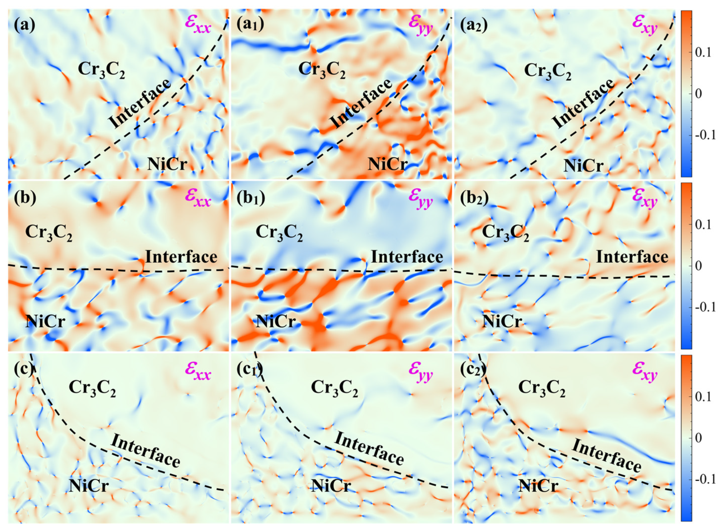
Geometric phase analysis (GPA) was employed to calculate and analyze the microscopic strain behavior based on the atomic lattice positions within the HRTEM images [73]. Figure 16a–c respectively show the strain fields in the εxx, εyy, and εxy directions corresponding to Figure 15d,e,h. On the GPA map, white on the +0.1 scale represents compressive stress, while blue on the −0.1 scale signifies tensile stress. Notably, the strain values in the carbide hard phases along the εxx, εyy, and εxy directions are significantly lower than those in the NiCr binder-phase matrix. Multiple high-strain regions are observed at the interface between the carbide hard phase and the NiCr matrix, where the elevated strain contributes to numerous mismatch errors. Furthermore, the compressive and tensile stresses at the interface help maintain stability between the carbide hard phase and the NiCr matrix, thereby counteracting part of the external load and absorbing the strain energy to accommodate the large plastic strain generated during wear, thus enhancing the wear resistance of the Cr3C2-NiCr coating.

3.6.5. Wear Mechanism

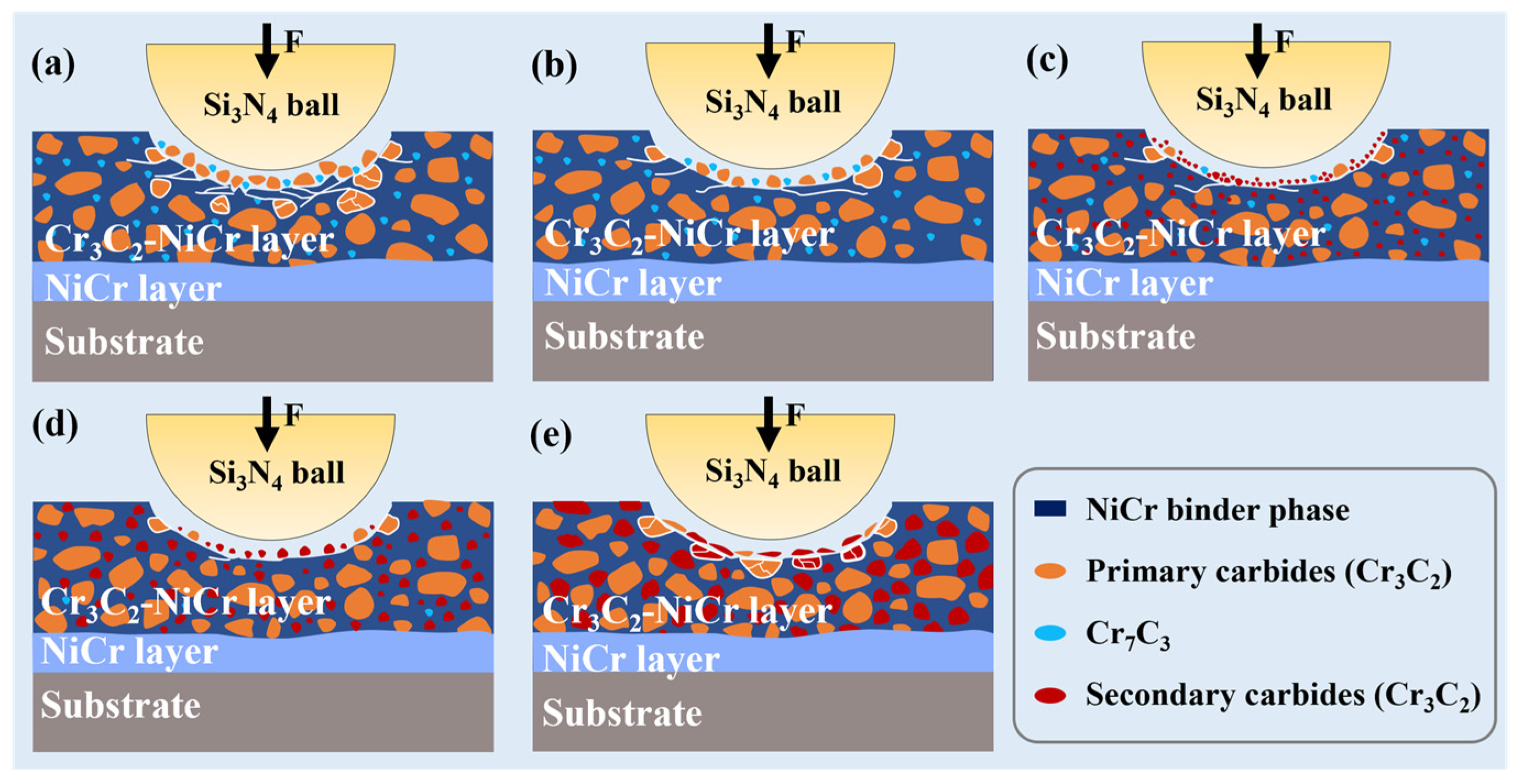
Given the preceding analysis, Figure 17 summarizes the evolution of carbides and the wear failure mechanism of the Cr3C2-25NiCr coating at different temperatures. The C-0 coating primarily consists of primary carbides, the NiCr binder phase, and a minor proportion of the metastable Cr7C3 phase, as depicted in Figure 17a. Brittle fracture leading to the shedding of primary carbides and causing severe abrasive wear is its predominant wear failure mechanism. Additionally, the numerous pores present in the C-0 coating exacerbate the abrasive wear process. The C-1 coating exhibits reduced porosity and enhanced microstructural uniformity, which increases fracture toughness and mitigates severe abrasive wear resulting from brittle fracture, as shown in Figure 17b. Additionally, hardness is a critical factor in enhancing wear resistance [74]. The precipitation of nano-secondary carbides in the C-2 coating significantly enhances its microhardness through a precipitation-strengthening effect. While the interface transition region formed by the nano-secondary carbides and the NiCr binder phase reduces interfacial energy and improves bonding strength, the nano-secondary carbides are more susceptible to being pulled out and forming abrasive grains under shear stress compared to the larger primary carbides. These nano-carbide abrasive grains create a rolling effect, which may account for the substantial reduction in the COF of the C-2 coating, as presented in Figure 17c. As the heat treatment temperature increases, the secondary carbides in the C-3 and C-4 coatings grow and aggregate, leading to a weakening of precipitation strengthening and a corresponding decrease in microhardness, which primarily accounts for the reduction in wear resistance. However, the substantial increase in fracture toughness and the reduction in porosity positively influence wear performance. Furthermore, the semi-coherent interface formed between the secondary carbides and the NiCr binder phase generates strong interfacial bonding, effectively suppressing the dislocation propagation caused by plastic deformation at the interface. Additionally, the relatively low energy of the semi-coherent interface enhances both thermal and mechanical stability, contributing to the toughening effect and minimizing cracking in the Cr3C2-25NiCr coating under friction. Consequently, spalling pits and grooves are rarely observed on the worn surface, with adhesive wear and slight oxidative wear identified as the primary wear mechanisms.

4. Conclusions

This study investigated the effects of vacuum heat treatment on the microstructure, carbide evolution, and wear mechanism of the HVOF-sprayed Cr3C2-25NiCr/NiCr coating. The main conclusions are as follows:
(1)
The Cr3C2-25NiCr coating primarily consists of the NiCr binder phase, the Cr3C2 phase, and a minor proportion of the Cr7C3 phase. Following heat treatment, the microstructure becomes denser, and the porosity significantly decreases with increasing heat treatment temperature.
(2)
Following heat treatment, nano-secondary carbides precipitate in the coating heat-treated at 600 °C. Solid-solution strengthening transitions to precipitation strengthening, resulting in a hardness increase of 29.1%. The fracture toughness of the coatings heat-treated at 800 °C and 1000 °C improves by 96.7% and 114.3%, respectively.
(3)
Wear tests show that heat treatment significantly decreases the coating’s wear rate. The coating heat-treated at 600 °C shows the best wear resistance, which results from the combined effects of a dense microstructure, elevated hardness, and enhanced fracture toughness.
(4)
The pull-out mechanism of carbides during wear is associated with carbide size and interface type. The polycrystalline interface transition region and semi-coherent interface formed by nano-secondary carbides and the NiCr binder phase exhibit relatively low interface energy. During wear, the nano-secondary carbides fall off and act as abrasive particles to achieve a rolling effect, significantly reducing the COF.
It should be noted that the wear tests in this study were conducted at room temperature using a high-hardness Si3N4 counterpart, which differs from the actual steam turbine service environment (high temperature, high pressure, and wet steam). Therefore, the absolute wear rate values cannot be directly extrapolated to real operating conditions. However, the comparative room-temperature tests effectively reveal the influence of heat treatment on the wear resistance of the coating. Future work will involve wear testing under high-temperature, high-pressure, and wet steam conditions to more comprehensively evaluate the actual service performance.

Author Contributions

J.C.: Writing—original draft, Data curation. W.W.: Supervision. K.H.: Investigation. X.G.: Methodology, Funding acquisition. X.C. (Xiaoying Cao): Software, Formal analysis, Data curation. Y.P.: Software. C.T.: Investigation. J.D.: Validation. X.C. (Xin Cao): Software, Methodology. Z.C.: Formal analysis, Funding acquisition, Methodology, Supervision. All authors have read and agreed to the published version of the manuscript.

Funding

This research was funded by the Key Program of the National Natural Science Foundation of China (U24B2050), Science and Technology Projects in Sichuan Province (2025YFHZ0163), and the National Natural Science Foundation of China (12402409).

Institutional Review Board Statement

Not applicable.

Informed Consent Statement

Not applicable.

Data Availability Statement

The data presented in this study are available upon request from the corresponding author due to privacy.

Acknowledgments

During the preparation of this manuscript/study, the authors used Grammarly software for the purposes of checking grammar and improving sentence formation. The authors have reviewed and edited the output and take full responsibility for the content of this publication.

Conflicts of Interest

Dongfang Electric Corporation Dongfang Turbine Co., had no role in the design of the study; in the collection, analysis, or interpretation of data; in the writing of the manuscript, or in the decision to publish the results. The authors declare that they have no known competing financial interests or personal relation-ships that could have appeared to influence the work reported in this paper.

References

  1. Hu, P.; Meng, Q.; Fan, T.; Cao, L.; Li, Q. Dynamic Response of Turbine Blade Considering a Droplet-Wall Interaction in Wet Steam Region. Energy 2023, 265, 126323. [Google Scholar] [CrossRef]
  2. Momeni Dolatabadi, A.; Moslehi, J.; Saffari Pour, M.; Mousavi Ajarostaghi, S.S.; Poncet, S.; Arıcı, M. Modified Model of Reduction Condensing Losses Strategy into the Wet Steam Flow Considering Efficient Energy of Steam Turbine Based on Injection of Nano-Droplets. Energy 2022, 242, 122951. [Google Scholar] [CrossRef]
  3. Schlobohm, J.; Bruchwald, O.; Frąckowiak, W.; Li, Y.; Kästner, M.; Pösch, A.; Reimche, W.; Maier, H.J.; Reithmeier, E. Advanced Characterization Techniques for Turbine Blade Wear and Damage. Procedia CIRP 2017, 59, 83–88. [Google Scholar] [CrossRef]
  4. Borel, M.O.; Nicoll, A.R.; Schläpfer, H.W.; Schmid, R.K. The Wear Mechanisms Occurring in Abradable Seals of Gas Turbines. Surf. Coat. Technol. 1989, 39–40, 117–126. [Google Scholar] [CrossRef]
  5. Carazas, F.; Souza, G. Availability Analysis of Gas Turbines Used in Power Plants. Int. J. Thermodyn. 2009, 12, 28–37. [Google Scholar]
  6. Bolelli, G.; Berger, L.-M.; Börner, T.; Koivuluoto, H.; Matikainen, V.; Lusvarghi, L.; Lyphout, C.; Markocsan, N.; Nylén, P.; Sassatelli, P.; et al. Sliding and Abrasive Wear Behaviour of HVOF- and HVAF-Sprayed Cr3C2-NiCr Hardmetal Coatings. Wear 2016, 358–359, 32–50. [Google Scholar] [CrossRef]
  7. Bian, Z.; Zheng, M.; Sun, Q.; Zhu, Z.; Zhu, S.; Cheng, J.; Liu, X.; Tan, H.; Yang, J. High-Temperature Tribological Properties of NiCr-Cr3C2 Cermet Coatings in Fluoride Molten Salts. Tribol. Int. 2024, 200, 110150. [Google Scholar] [CrossRef]
  8. Zhou, W.; Zhou, K.; Li, Y.; Deng, C.; Zeng, K. High Temperature Wear Performance of HVOF-Sprayed Cr3C2-WC-NiCoCrMo and Cr3C2-NiCr Hardmetal Coatings. Appl. Surf. Sci. 2017, 416, 33–44. [Google Scholar] [CrossRef]
  9. Feng, K.; Wang, T.; Liang, Y.; Wang, R.; Wang, C.; Shao, T. Thermal-Mechanical Driven Oxidation of NiCr-Cr3C2-BaF2/CaF2 Composite Coating at High Temperature. Corros. Sci. 2022, 208, 110698. [Google Scholar] [CrossRef]
  10. Wang, J.H.; Li, D.G.; Shao, T.M. Hot Corrosion Behavior of NiCr-Cr3C2-CaF2/BaF2 Composite Coating with NiAl Bond Coating in Molten NaCl-KCl and NaCl-Na2SO4 at 800 °C. Corros. Sci. 2022, 206, 110554. [Google Scholar] [CrossRef]
  11. Ozkan, D. Structural Characteristics and Wear, Oxidation, Hot Corrosion Behaviors of HVOF Sprayed Cr3C2-NiCr Hardmetal Coatings. Surf. Coat. Technol. 2023, 457, 129319. [Google Scholar] [CrossRef]
  12. Hardwicke, C.U.; Lau, Y.-C. Advances in Thermal Spray Coatings for Gas Turbines and Energy Generation: A Review. J. Therm. Spray Technol. 2013, 22, 564–576. [Google Scholar] [CrossRef]
  13. Gong, T.; Yao, P.; Zuo, X.; Zhang, Z.; Xiao, Y.; Zhao, L.; Zhou, H.; Deng, M.; Wang, Q.; Zhong, A. Influence of WC Carbide Particle Size on the Microstructure and Abrasive Wear Behavior of WC–10Co–4Cr Coatings for Aircraft Landing Gear. Wear 2016, 362–363, 135–145. [Google Scholar] [CrossRef]
  14. Suresh Babu, P.; Basu, B.; Sundararajan, G. Abrasive Wear Behavior of Detonation Sprayed WC–12Co Coatings: Influence of Decarburization and Abrasive Characteristics. Wear 2010, 268, 1387–1399. [Google Scholar] [CrossRef]
  15. Poirier, D.; Legoux, J.-G.; Lima, R.S. Engineering HVOF-Sprayed Cr3C2-NiCr Coatings: The Effect of Particle Morphology and Spraying Parameters on the Microstructure, Properties, and High Temperature Wear Performance. J. Therm. Spray Technol. 2013, 22, 280–289. [Google Scholar] [CrossRef]
  16. Geng, Z.; Hou, S.; Shi, G.; Duan, D.; Li, S. Tribological Behaviour at Various Temperatures of WC-Co Coatings Prepared Using Different Thermal Spraying Techniques. Tribol. Int. 2016, 104, 36–44. [Google Scholar] [CrossRef]
  17. Yang, M.; Jin, Q.; Huang, T.; Kong, D.; Song, P. Effect of Cr3C2 Distribution on the Wear and Corrosion Properties of HVOF-Sprayed WC–12Co/Cr3C2–25NiCr Composite Coatings. Ceram. Int. 2024, 50, 19720–19732. [Google Scholar] [CrossRef]
  18. Matthews, S. Development of High Carbide Dissolution/Low Carbon Loss Cr3C2–NiCr Coatings by Shrouded Plasma Spraying. Surf. Coat. Technol. 2014, 258, 886–900. [Google Scholar] [CrossRef]
  19. Liu, Q.; Bai, Y.; Wang, H.D.; Ma, G.Z.; Liu, M.; Chu, C.Y.; Sun, Y.W.; Fan, W.; Ding, F.; Zhao, B.; et al. Microstructural Evolution of Carbides and Its Effect on Tribological Properties of SAPS or HVOF Sprayed NiCr–Cr3C2 Coatings. J. Alloys Compd. 2019, 803, 730–741. [Google Scholar] [CrossRef]
  20. Liu, Q.; He, T.; Guo, W.Y.; Bai, Y.; Ma, Y.S.; Chang, Z.D.; Liu, H.B.; Zhou, Y.X.; Ding, F.; Sun, Y.W.; et al. Tribological Behavior of SAPS Sprayed Al2O3-TiO2 and NiCr-Cr3C2 Coatings under Severe Load Conditions. Surf. Coat. Technol. 2019, 370, 362–373. [Google Scholar] [CrossRef]
  21. Liu, X.; Shen, C.; Hu, K.; Zhang, S.; Xue, Z.; Yang, Y. Improvement in High-Velocity Air-Fuel-Sprayed Cr3C2-NiCr/(NiAl, NiCr) Composite Coatings by Annealing Heat Treatment. J. Mater. Eng. Perform. 2023, 32, 199–210. [Google Scholar] [CrossRef]
  22. Murthy, J.K.N.; Satya Prasad, K.; Gopinath, K.; Venkataraman, B. Characterisation of HVOF Sprayed Cr3C2-50(Ni20Cr) Coating and the Influence of Binder Properties on Solid Particle Erosion Behaviour. Surf. Coat. Technol. 2010, 204, 3975–3985. [Google Scholar] [CrossRef]
  23. Yin, B.; Liu, G.; Zhou, H.; Chen, J.; Yan, F. Sliding Wear Behavior of HVOF-Sprayed Cr3C2–NiCr/CeO2 Composite Coatings at Elevated Temperature up to 800 °C. Tribol. Lett. 2010, 37, 463–475. [Google Scholar] [CrossRef]
  24. ASM Hand Book Committee. Properties and selection: Stainless steels, tool materials, and special purpose metals. Met. Hand Book 1980, 3, 17. [Google Scholar]
  25. Karaoglanli, A.C.; Grund, T.; Turk, A.; Lampke, T. A Comparative Study of Oxidation Kinetics and Thermal Cyclic Performance of Thermal Barrier Coatings (TBCs). Surf. Coat. Technol. 2019, 371, 47–67. [Google Scholar] [CrossRef]
  26. Stewart, D.A.; Shipway, P.H.; McCartney, D.G. Abrasive Wear Behaviour of Conventional and Nanocomposite HVOF-Sprayed WC–Co Coatings. Wear 1999, 225–229, 789–798. [Google Scholar] [CrossRef]
  27. Ertürk, M.T.; Tirkeş, S.; Gür, C.H. Investigating the Effects of CoMoCrSi Powder Composition and Particle Size, and Annealing Heat Treatment on Microstructure and Mechanical and Tribological Performance of HVOF Sprayed Coatings. Met. Mater. Int. 2024, 30, 3268–3293. [Google Scholar] [CrossRef]
  28. Schubert, J.; Česánek, Z.; Houdková, Š. Influence of Heat-Treatment Methods on Mechanical and Erosion Properties of Thermally Sprayed NiCrBSi Based Coating. In Proceedings of the International Thermal Spray Conference, Shanghai, China, 10–12 May 2016; DVS Media GmbH: Düsseldorf, Germany, 2026; pp. 783–788. [Google Scholar]
  29. Illana, A.; de Miguel, M.T.; García-Martín, G.; Gonçalves, F.P.; Sousa, M.G.; Pérez, F.J. Experimental Study on Steam Oxidation Resistance at 600 °C of Inconel 625 Coatings Deposited by HVOF and Laser Cladding. Surf. Coat. Technol. 2022, 451, 129081. [Google Scholar] [CrossRef]
  30. Stavropoulos, P.; Bikas, H.; Avram, O.; Valente, A.; Chryssolouris, G. Hybrid Subtractive–Additive Manufacturing Processes for High Value-Added Metal Components. Int. J. Adv. Manuf. Technol. 2020, 111, 645–655. [Google Scholar] [CrossRef]
  31. Matthews, S.; Berger, L.-M. Long-Term Compositional/Microstructural Development of Cr3C2-NiCr Coatings at 500 °C, 700 °C and 900 °C. Int. J. Refract. Met. Hard Mater. 2016, 59, 1–18. [Google Scholar] [CrossRef]
  32. Evans, A.G.; Wilshaw, T.R. Quasi-Static Solid Particle Damage in Brittle Solids—I. Observations Analysis and Implications. Acta Metall. 1976, 24, 939–956. [Google Scholar] [CrossRef]
  33. Matikainen, V.; Bolelli, G.; Koivuluoto, H.; Sassatelli, P.; Lusvarghi, L.; Vuoristo, P. Sliding Wear Behaviour of HVOF and HVAF Sprayed Cr3C2-Based Coatings. Wear 2017, 388–389, 57–71. [Google Scholar] [CrossRef]
  34. Murthy, J.K.N.; Bysakh, S.; Gopinath, K.; Venkataraman, B. Microstructure Dependent Erosion in Cr3C2–20(NiCr) Coating Deposited by a Detonation Gun. Surf. Coat. Technol. 2007, 202, 1–12. [Google Scholar] [CrossRef]
  35. Matthews, S.; James, B.; Hyland, M. The Role of Microstructure in the Mechanism of High Velocity Erosion of Cr3C2–NiCr Thermal Spray Coatings: Part 1—As-Sprayed Coatings. Surf. Coat. Technol. 2009, 203, 1086–1093. [Google Scholar] [CrossRef]
  36. Matthews, S.; James, B.; Hyland, M. The Role of Microstructure in the High Temperature Oxidation Mechanism of Cr3C2–NiCr Composite Coatings. Corros. Sci. 2009, 51, 1172–1180. [Google Scholar] [CrossRef]
  37. Janka, L.; Norpoth, J.; Trache, R.; Berger, L.-M. Influence of Heat Treatment on the Abrasive Wear Resistance of a Cr3C2NiCr Coating Deposited by an Ethene-Fuelled HVOF Spray Process. Surf. Coat. Technol. 2016, 291, 444–451. [Google Scholar] [CrossRef]
  38. Hao, E.; An, Y.; Liu, X.; Wang, Y.; Zhou, H.; Yan, F. Effect of Annealing Treatment on Microstructures, Mechanical Properties and Cavitation Erosion Performance of High Velocity Oxy-Fuel Sprayed NiCoCrAlYTa Coating. J. Mater. Sci. Technol. 2020, 53, 19–31. [Google Scholar] [CrossRef]
  39. Wakai, A.; Bustillos, J.; Sargent, N.; Stokes, J.L.; Xiong, W.; Smith, T.M.; Moridi, A. Harnessing Metastability for Grain Size Control in Multiprincipal Element Alloys during Additive Manufacturing. Nat. Commun. 2025, 16, 1446. [Google Scholar] [CrossRef] [PubMed]
  40. Zhu, L.; Li, G.; Dong, W.; Zhang, J.; Ma, Y.; He, H.; Lan, S.; Wu, Z.; Li, X.; Yang, T.; et al. On the Grain Size Dependence of Competing Deformation Mechanisms in a CrCoNi Medium Entropy Alloy. Acta Mater. 2025, 289, 120907. [Google Scholar] [CrossRef]
  41. Huang, Y.; Langdon, T.G. Advances in Ultrafine-Grained Materials. Mater. Today 2013, 16, 85–93. [Google Scholar] [CrossRef]
  42. Shi, L.; Long, Y.; Wang, Y.; Chen, X.; Zhao, Q. On-Line Detection of Porosity Change of High Temperature Blade Coating for Gas Turbine. Infrared Phys. Technol. 2020, 110, 103415. [Google Scholar] [CrossRef]
  43. Ma, W.; Bu, Z.; Sun, C.; An, Y.; Zhao, X. Influence of Porosity Distribution and Toughening Effect on the Tribological Properties of Al2O3-Y2O3 Coatings with Different Y2O3 Contents. Ceram. Int. 2025, 51, 7809–7824. [Google Scholar] [CrossRef]
  44. Fotoohinezhadkhales, M.; Roy, A.; Ben Ettouil, F.; Asuquo, M.; Moreau, C.; Stoyanov, P. Microstructural Insights and Temperature Effects on Wear Resistance of CuNiIn Coatings: Comparison of HVOF and HVAF Processes. Tribol. Int. 2025, 205, 110541. [Google Scholar] [CrossRef]
  45. Dent, A.H.; Horlock, A.J.; McCartney, D.G.; Harris, S.J. Microstructural Characterisation of a Ni-Cr-B-C Based Alloy Coating Produced by High Velocity Oxy-Fuel Thermal Spraying. Surf. Coat. Technol. 2001, 139, 244–250. [Google Scholar] [CrossRef]
  46. Lv, B.; Fan, X.; Li, D.; Wang, T.J. Towards Enhanced Sintering Resistance: Air-Plasma-Sprayed Thermal Barrier Coating System with Porosity Gradient. J. Eur. Ceram. Soc. 2018, 38, 1946–1956. [Google Scholar] [CrossRef]
  47. Tang, L.; He, P.; Kang, J.; Wang, L.; Ding, S.; Chen, S.; Zhu, X.; Xie, F.; Zhou, L.; Ma, G.; et al. Significantly Enhanced Mechanical and Tribological Properties of Co-Based Alloy Coatings by Annealing Treatment. Tribol. Int. 2020, 146, 106265. [Google Scholar] [CrossRef]
  48. Tao, Y.-F.; Li, J.; Lv, Y.-H.; Hu, L.-F. Effect of Heat Treatment on Residual Stress and Wear Behaviors of the TiNi/Ti2Ni Based Laser Cladding Composite Coatings. Opt. Laser Technol. 2017, 97, 379–389. [Google Scholar] [CrossRef]
  49. Guo, Q.; Liu, H.; Sun, C.; Cao, Y.; Lu, X.; Du, Y.; Ru, X.; Xu, H.; Song, K.; Fu, P.; et al. Dual-Gradient Structure Enhances Wear Resistance of Aero-Engine Bearing Steel by Suppressing Strain Localization. Acta Mater. 2025, 289, 120919. [Google Scholar] [CrossRef]
  50. Lu, M.; Wang, H.; Song, X.; Sun, F. Effect of Doping Level on Residual Stress, Coating-Substrate Adhesion and Wear Resistance of Boron-Doped Diamond Coated Tools. J. Manuf. Process. 2023, 88, 145–156. [Google Scholar] [CrossRef]
  51. Richert, M.; Leszczyńska-Madej, B. Effect of the Annealing on the Microstructure of HVOF Deposited Coatings. J. Achiev. Mater. Manuf. Eng. 2011, 46, 95–102. [Google Scholar]
  52. Haasen, P.; Mordike, B.L. Physical Metallurgy, 3rd ed.; Cambridge University Press: Cambridge, UK, 1996; ISBN 978-0-521-55092-5. [Google Scholar]
  53. Ibrahim, I.A.; Mohamed, F.A.; Lavernia, E.J. Particulate Reinforced Metal Matrix Composites—A Review. J. Mater. Sci. 1991, 26, 1137–1156. [Google Scholar] [CrossRef]
  54. Ast, J.; Ghidelli, M.; Durst, K.; Göken, M.; Sebastiani, M.; Korsunsky, A.M. A Review of Experimental Approaches to Fracture Toughness Evaluation at the Micro-Scale. Mater. Des. 2019, 173, 107762. [Google Scholar] [CrossRef]
  55. Li, A.; Alidokht, S.A.; Vo, P.; Jodoin, B.; Chromik, R.R. Role of Tamping Effect in Wear Behavior of Cu-TiC Composite Coatings Deposited by Cold Spray. Wear 2025, 570, 205914. [Google Scholar] [CrossRef]
  56. Govande, A.R.; Chandak, A.; Sunil, B.R.; Dumpala, R. Carbide-Based Thermal Spray Coatings: A Review on Performance Characteristics and Post-Treatment. Int. J. Refract. Met. Hard Mater. 2022, 103, 105772. [Google Scholar] [CrossRef]
  57. Kiilakoski, J.; Musalek, R.; Lukac, F.; Koivuluoto, H.; Vuoristo, P. Evaluating the Toughness of APS and HVOF-Sprayed Al2O3-ZrO2-Coatings by in-Situ- and Macroscopic Bending. J. Eur. Ceram. Soc. 2018, 38, 1908–1918. [Google Scholar] [CrossRef]
  58. Cao, S.; Chang, Z.; Li, S.; Zhang, W.; Xu, S. Effect of Binder Phases on the Microstructure and Sliding Wear Properties of HVOF-Sprayed WC-Based Coatings. Int. J. Refract. Met. Hard Mater. 2024, 122, 106742. [Google Scholar] [CrossRef]
  59. Zhang, P.; Yao, Z.; Huang, L.; Wang, X.; Lin, S.; Liu, Y.; Lu, S.; Wu, X. Construction of Biphasic FeCrAlWx High Entropy Alloys Coating of BCC and Al-Rich FCC Second Phase for Dual Enhancement of Strength and Plasticity. Surf. Coat. Technol. 2023, 469, 129793. [Google Scholar] [CrossRef]
  60. Liu, J.; Deng, X.T.; Huang, L.; Wang, Z.D. Friction and Wear Behavior of Nano/Ultrafine-Grained and Heterogeneous Ultrafine-Grained 18Cr–8Ni Austenitic Stainless Steels. Tribol. Int. 2020, 152, 106520. [Google Scholar] [CrossRef]
  61. Fu, L.; Han, W.; Zhao, L.; Gong, K.; Bengtsson, S.; Zhou, M.; Li, C.; Tian, Z. Effects of Cr3C2 Content and Temperature on Sliding Friction and Wear Behaviors of Cr3C2/Ni3Al Composite Materials. Wear 2018, 414–415, 163–173. [Google Scholar] [CrossRef]
  62. Zhang, D.; Peng, Z.; Liu, Z.; Yu, J.; Yuan, L. Tribological Characteristics of WC-Cr3C2-Ni Cermet Coatings under Different Wear Parameters. J. Aust. Ceram. Soc. 2024, 60, 871–884. [Google Scholar] [CrossRef]
  63. Ran, X.; Shang, J.; Wang, L.; Zhang, X. Effect of Porosity on Wear Behaviour of Remanufacturing Cr3C2-NiCr Coatings under Oil Lubrication. Procedia Manuf. 2020, 43, 487–494. [Google Scholar] [CrossRef]
  64. Zhou, D.; Qiu, F.; Jiang, Q. Simultaneously Increasing the Strength and Ductility of Nano-Sized TiN Particle Reinforced Al–Cu Matrix Composites. Mater. Sci. Eng. A 2014, 596, 98–102. [Google Scholar] [CrossRef]
  65. Zhou, D.; Qiu, F.; Wang, H.; Jiang, Q. Manufacture of Nano-Sized Particle-Reinforced Metal Matrix Composites: A Review. Acta Metall. Sin. (Engl. Lett.) 2014, 27, 798–805. [Google Scholar] [CrossRef]
  66. Ji, C.; Sun, S.; Wang, B.; Lin, B. Molecular Dynamic Simulations of the Roles of Nanoparticles in Sliding Friction Process. Chem. Phys. Lett. 2019, 728, 44–49. [Google Scholar] [CrossRef]
  67. Brandl, C.; Germann, T.C.; Misra, A. Structure and Shear Deformation of Metallic Crystalline–Amorphous Interfaces. Acta Mater. 2013, 61, 3600–3611. [Google Scholar] [CrossRef]
  68. Zhang, Y.; Chong, K.; Liu, Q.; Bai, Y.; Zhang, Z.; Wu, D.; Zou, Y. High-Temperature Tribological Behavior of Thermally-Treated Supersonic Plasma Sprayed Cr3C2-NiCr Coatings. Int. J. Refract. Met. Hard Mater. 2021, 95, 105456. [Google Scholar] [CrossRef]
  69. Bramfitt, B.L. The Effect of Carbide and Nitride Additions on the Heterogeneous Nucleation Behavior of Liquid Iron. Metall. Trans. 1970, 1, 1987–1995. [Google Scholar] [CrossRef]
  70. Xu, Z.; Zhang, X.; Zhao, N.; He, C. Synergistic Strengthening Effect of in-Situ Synthesized WC1-x Nanoparticles and Graphene Nanosheets in Copper Matrix Composites. Compos. Part A Appl. Sci. Manuf. 2020, 133, 105891. [Google Scholar] [CrossRef]
  71. Shin, S.E.; Choi, H.J.; Hwang, J.Y.; Bae, D.H. Strengthening Behavior of Carbon/Metal Nanocomposites. Sci. Rep. 2015, 5, 16114. [Google Scholar] [CrossRef]
  72. Shao, S.; Wang, J.; Misra, A.; Hoagland, R.G. Spiral Patterns of Dislocations at Nodes in (111) Semi-Coherent FCC Interfaces. Sci. Rep. 2013, 3, 2448. [Google Scholar] [CrossRef]
  73. Pofelski, A.; Zhu, Y.; Botton, G.A. Relation between Sampling, Sensitivity and Precision in Strain Mapping Using the Geometric Phase Analysis Method in Scanning Transmission Electron Microscopy. Ultramicroscopy 2024, 255, 113842. [Google Scholar] [CrossRef]
  74. Qin, D.; Xu, G.; Yang, Y.; Chen, S. Multiphase Ceramic Coatings with High Hardness and Wear Resistance on 5052 Aluminum Alloy by a Microarc Oxidation Method. ACS Sustain. Chem. Eng. 2018, 6, 2431–2437. [Google Scholar] [CrossRef]
Figure 1. Powder characterization: (a,b) Cr3C2-25NiCr powder, (c,d) corresponding EDS, (e,f) NiCr powder, (g,h) corresponding EDS pattern.
Applmech 07 00048 g001
Figure 2. Schematic diagram of HVOF spraying system: (a) spraying system, (b) spraying technology principle, and (c) coating structure.
Applmech 07 00048 g002
Figure 3. Friction wear tester: (a) Schematic drawing and (b) physical setup.
Applmech 07 00048 g003
Figure 4. (a) XRD patterns of powders and coating at different temperatures, (b) the magnified main peak.
Applmech 07 00048 g004
Figure 5. SEM and EDS images of coating cross-sections: (aa3) C-0, (bb3) C-1, (cc3) C-2, (dd3) C-3, (ee3) C-4.
Applmech 07 00048 g005
Figure 6. IPF plots and grain size statistics of EBSD characterization: (aa3) C-0, (bb3) C-1, (cc3) C-2, (dd3) C-3, (ee3) C-4.
Applmech 07 00048 g006
Figure 7. EBSD phase diagrams and percentage of content: (a,a1) C-0, (b,b1) C-1, (c,c1) C-2, (d,d1) C-3, (e,e1) C-4, (f) phase percentage.
Applmech 07 00048 g007
Figure 8. Statistical results of porosity: (a) C-0, (b) C-1, (c) C-2, (d) C-3, (e) C-4, (f) porosity statistics results.
Applmech 07 00048 g008
Figure 9. Surface roughness and height: (a) C-0, (b) C-1, (c) C-2, (d) C-3, (e) C-4, (f) roughness profile.
Applmech 07 00048 g009
Figure 10. (a) microhardness curve, (b) surface residual stress.
Applmech 07 00048 g010
Figure 11. Indentation crack morphology and fracture toughness: (a) C-0, (b) C-1, (c) C-2, (d) C-3, (e) C-4, (f) fracture toughness value.
Applmech 07 00048 g011
Figure 12. Wear test data: (a) COF curve, (b) wear rate and volume.
Applmech 07 00048 g012
Figure 13. Three-dimensional morphologies of wear surface and wear profile: (a) C-0, (b) C-1, (c) C-2, (d) C-3, (e) C-4, (f) statistical results of wear depth and width.
Applmech 07 00048 g013
Figure 14. Surface wear morphology and local magnification (a,a1) C-0, (b,b1) C-1, (cc2) C-2, (d,d1) C-3, (ee2) C-4, (f) EDS results for the corresponding region.
Applmech 07 00048 g014
Figure 15. TEM images of wear subsurface: (a) BF image of C-2, (b) EDS spectra of (a), (c,c1) HRTEM images of region A and FFT, (dd2) HRTEM images of region B and corresponding FFT, (ee5) HRTEM images of region C and corresponding FFT and IFFT, (f) BF image of C-4, (g,g1) HRTEM images of region D corresponding FFT, (hh2) HRTEM images of region E and corresponding FFT.
Applmech 07 00048 g015
Figure 16. GPA maps of strain fields (εxx, εyy, and εxy) at different interfacial regions: (aa2) region B, (bb2) region C, and (cc2) region E.
Applmech 07 00048 g016
Figure 17. Wear mechanism diagrams: (a) C-0, (b) C-1, (c) C-2, (d) C-3, (e) C-4.
Applmech 07 00048 g017
Table 1. Co3W3 steel chemical composition (wt.%).
ElementCrCoWNiMnMoVNbNFe
Content10.453.112.600.680.470.220.180.080.04Bal
Table 2. Experimental values of the lattice parameters of Cr3C2 and NiCr.
[hkl]Cr3C2[uvw]Ni(Cr)d[hkl] (nm)d[uvw] (nm)θ (°)ε (%)
-120-1110.27150.205312.521.7
-1-410020.19030.189832.7
0-611-110.24510.20304.5
Disclaimer/Publisher’s Note: The statements, opinions and data contained in all publications are solely those of the individual author(s) and contributor(s) and not of MDPI and/or the editor(s). MDPI and/or the editor(s) disclaim responsibility for any injury to people or property resulting from any ideas, methods, instructions or products referred to in the content.