


Abstract
The present study investigates the influence of geometric parameters on the vibro-acoustic performance of piezoelectric speakers, with the objective of establishing quantitative design guidelines for resonance tuning and sound pressure level (SPL) enhancement. Understanding the dimension-dependent behavior of such devices is essential for the development of compact and efficient acoustic transducers. To this end, a fully coupled electromechanical–acoustic finite element model is developed in the frequency domain, incorporating linear piezoelectric constitutive relations, structural dynamics, and an external acoustic air domain. The model systematically examines the effects of variations in piezoelectric disc thickness, brass diaphragm thickness, and diaphragm radius. The results demonstrate that increasing the piezoelectric disc thickness leads to a noticeable increase in resonance frequency and a measurable enhancement in SPL due to strengthened electromechanical coupling. In contrast, reducing the brass membrane thickness primarily shifts the resonance frequency to lower values, while producing negligible changes in SPL amplitude. Furthermore, enlarging the diaphragm radius significantly decreases the fundamental resonance frequency, confirming its dominant influence on stiffness-controlled vibration behavior. These findings quantitatively establish the relationship between geometric design parameters and acoustic response, providing a predictive framework for performance optimization. The proposed modeling approach offers an effective and reliable tool for the design and refinement of high-performance piezoelectric speaker systems.
1. Introduction
The phenomenon of piezoelectricity involves the generation of an electric charge in certain materials when subjected to mechanical stress (direct piezoelectric effect) and, conversely, the deformation of these materials when subjected to an electric field (inverse piezoelectric effect) [1]. Piezoelectric materials, due to these properties, are used for various applications where the conversion of mechanical energy into electrical energy and vice versa is required. Applications can be found in numerous sectors, including electronics, consumer electronics, mechanical engineering, robotics, environmental monitoring, civil engineering and infrastructure monitoring, nanotechnology, acoustic and audio, automotive, medical, energy harvesting, aerospace, and defense [1,2].
Applications of piezoelectric materials in acoustics for infrasound include medical applications such as studying the mechanics of the heart [1], military applications [3] and detection of cracks by infrasonic sensors [4]. Application for ultrasound include sonar [5], directional loudspeakers [6], and medical imaging [1], while applications in the audible range of sound include noise suppression to reduce the internal noise in aircrafts [7], control of vibrations in active machinery [8] and applications from micro-speakers in hearing aids [9].
Sound generation is a central topic in acoustics [10,11] and a primary application of piezoelectric materials. Although piezoelectric transducers exhibit a broad frequency response (approximately 200 Hz to 100 kHz), their low-frequency performance is generally inferior to that of conventional dynamic speakers [12]. Nevertheless, their compact size, structural simplicity, and low power consumption enable competitive sound pressure levels, making them particularly suitable for portable and space-constrained electronic devices.
Modern piezoelectric speakers primarily use lead zirconate titanate (PZT) and polyvinylidene fluoride (PVDF) for sound generation via the inverse piezoelectric effect [13]. PZT ceramics are typically implemented in multilayer thin-diaphragm structures for efficient electromechanical conversion [14], while PVDF films are employed in microstructured membranes, allowing performance tuning through geometric optimization [15]. Their thin profiles, flexibility, and low power consumption make these materials well suited for miniaturized acoustic devices such as microspeakers and high-intensity focused ultrasound transducers [16]. Advances in fabrication, including wafer-bonding techniques, have further enhanced acoustic output, with reported SPLs up to 110 dB in the 1–4.5 kHz range [12], demonstrating the ongoing potential of compact, high-performance piezoelectric transducers.
Regarding the modeling and improvement of piezoelectric speakers, finite element analysis (FEA) is an important tool (and in acoustics in general [17]), capable of capturing complex interactions that analytical methods often struggle with [18,19]. Coupled electrostatic-structural-acoustic simulations, predict displacement distributions, electric potential, and acoustic wave propagation in various structures [15,19,20,21]. These models can account for layers and dimensions such as silicon thickness, piezo layer, and gap heights significantly influence the vibro-acoustic performance [20]. Axisymmetric 2D FEA is often favored for efficiency in high aspect-ratio Micro-Electro-Mechanical Systems (MEMS) devices, validating analytical predictions of radial and thickness-dependent responses [18].
Despite the numerous advantages of piezoelectric speakers, their performance is generally not optimal at lower frequencies, where acoustic output and radiation efficiency tend to be less effective [13,16]. This necessitates advanced design considerations, such as mechanical amplification to mitigate these issues [13]. While piezoelectric transducers excel in high-frequency accuracy, they require dimension-specific FEA to balance the trade-offs between bandwidth, efficiency, and sound pressure level [16]. Previous works highlight the superiority of FEA for non-piston-like motions in finite disks, where radial-thickness dependencies preclude simple analytical solutions [18]. However, there remains a gap in systematic parametric studies that directly link diaphragm radius and thickness to broadband acoustic metrics, motivating the development of comprehensive coupled FEA frameworks for predictive design [19,20]. Understanding the intricate relationship between geometric dimensions and the acoustic output of these speakers is therefore essential. This knowledge is critical for improving acoustic performance and guiding the design of compact and efficient piezoelectric speaker systems.
The purpose of this study is to investigate the dimension-dependent vibro-acoustic behavior of piezoelectric speakers and to evaluate how variations in geometric parameters influence their sound generation characteristics. Specifically, this research systematically varies parameters such as diaphragm radius and thickness to quantify their influence on resonance frequencies, vibration amplitudes, and sound pressure levels. This detailed analysis seeks to provide a robust framework for optimizing the design of piezoelectric speakers, enabling enhanced acoustic performance across diverse applications.
2. Methods
2.1. Geometry and Modeling Approach
The piezoelectric speaker investigated in this study is a unimorph-type transducer. The device consists of a circular piezoelectric ceramic layer bonded to a thin brass diaphragm. When subjected to an alternating electric field, the piezoelectric layer induces bending of the diaphragm, generating pressure waves in the surrounding air.
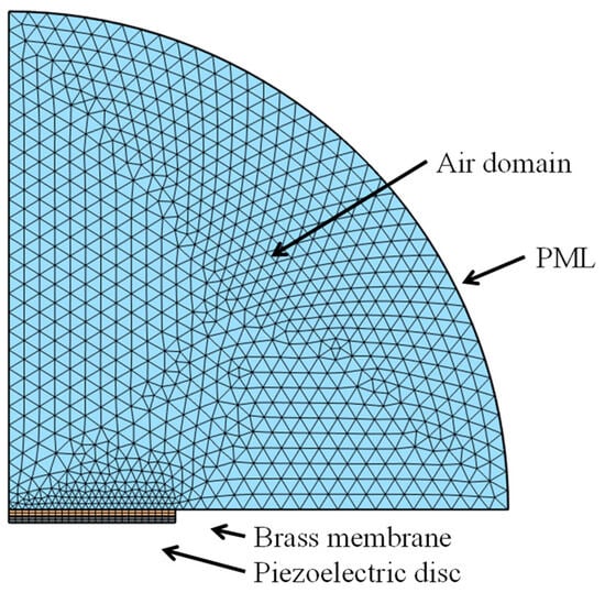
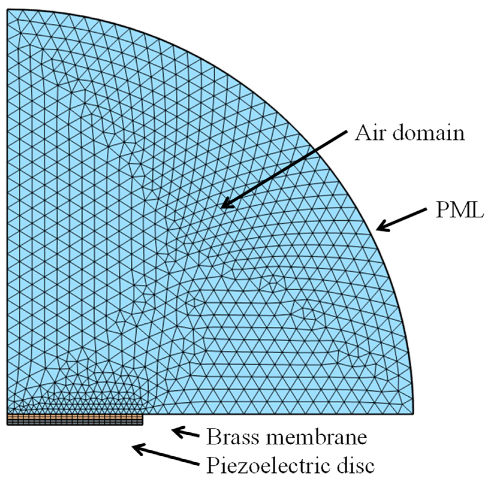
Due to the rotational symmetry of both the diaphragm and piezoelectric layer, the problem is formulated as a two-dimensional axisymmetric finite element model, which significantly reduces computational cost while accurately capturing the coupled electromechanical–acoustic behavior. The axisymmetric geometry of the model, including the piezoelectric disk, brass membrane, surrounding air domain, and perfectly matched layer (PML) is shown in Figure 1.
Figure 1.
Axisymmetric geometry of the model, illustrating the piezoelectric disk, the brass membrane, the surrounding air domain, and the perfectly matched layer (PML).
2.2. Governing Equations
The numerical model couples structural mechanics, electrostatics, and acoustics within a frequency-domain finite element framework.
2.2.1. Piezoelectric Constitutive Relations
The piezoelectric domain is modeled using the linear piezoelectric constitutive equations in stress–charge form:
where
- is the stress tensor,
- is the infinitesimal strain tensor,
- is the electric field,
- is the electric displacement vector,
- is the elastic stiffness tensor at constant electric field,
- is the piezoelectric coupling tensor,
- is the permittivity tensor at constant strain,
- is the electric potential.
The piezoelectric material is PZT-5H, whose material properties are taken from COMSOL’s built-in material library (material properties of PZT-5H are included in the Appendix A, Table A1).
2.2.2. Structural Dynamics
The mechanical behavior of both the piezoelectric layer and the brass diaphragm is governed by the linear theory of elasticity under small deformations. The strain field is related to the displacement field through the infinitesimal strain–displacement relations:
where
- is the displacement vector
The mechanical behavior of both the piezoelectric layer and brass diaphragm is governed by the linear elastodynamic equation in the frequency domain:
where
- is the angular frequency,
- is the material density,
- represents body forces (neglected in this study).
The outer edge of the brass diaphragm is mechanically fixed, representing a clamped boundary condition.
2.2.3. Electrostatics
The electric potential distribution in the piezoelectric layer is obtained from Gauss’s law in differential form:
An alternating electric potential of 5 V is applied to the upper electrode surface of the piezoelectric layer, while the lower electrode is grounded.
2.2.4. Acoustic Domain
The surrounding air is modeled as a linear, lossless acoustic medium governed by the Helmholtz equation for harmonic pressure fluctuations:
where
- is the acoustic pressure,
- is the density of air,
- is the speed of sound in air.
2.3. Fluid–Structure Coupling
At the interface between the solid diaphragm and the acoustic domain, bidirectional coupling is enforced:
This ensures energy-consistent coupling between the structural vibration and sound radiation.
2.4. Boundary Conditions and Absorbing Layer
The outer edge of the brass diaphragm is mechanically fixed, imposing a clamped boundary condition (). The piezoelectric layer is perfectly bonded to the brass diaphragm, and therefore displacement continuity is enforced at their interface. No additional mechanical boundary condition is prescribed at the lower surface of the piezoelectric layer, as it constitutes an internal solid–solid interface within the coupled structural domain.
To simulate an unbounded acoustic domain and satisfy the Sommerfeld radiation condition [22] a perfectly matched layer (PML) surrounds the air domain. The PML is an approximation methodology originally developed by Berenger [23] for electromagnetic modeling calculations but was later developed for acoustic waves [24] and applied in the field of acoustics. The PML attenuates outgoing acoustic waves with minimal reflection for all incidence angles and frequencies [25]. This approach is widely recognized as one of the most effective absorbing boundary conditions for frequency-domain acoustic simulations (for a review of absorbing boundary conditions the reader can refer to [26,27]).
2.5. Finite Element Discretization
The governing equations are discretized using the finite element method (FEM) and solved in the frequency domain using COMSOL Multiphysics v6.1 (COMSOL Inc., Burlington, VT, USA). The acoustic domain (air) is discretized using quadratic Lagrange triangular elements. The maximum element size is determined according to the commonly used spatial resolution criterion (Equation (9)), where is the wavelength corresponding to the highest simulated frequency (20 kHz) and is the maximum element size. This ensures adequate resolution of acoustic wave propagation. Five elements per wavelength are typical [28] for acoustic modeling in the frequency domain, while different considerations apply for modeling in the time domain [29].
The structural domains, including the piezoelectric layer and brass diaphragm, are discretized using compatible quadratic elements to ensure accurate electromechanical coupling. Mesh refinement in these thin plates is governed primarily by bending accuracy and strain resolution rather than by bulk elastic wavelength. In particular:
- Through-thickness discretization: five elements are used across the thickness of both the piezoelectric and brass layers to capture bending deformation and stress gradients accurately.
- In-plane discretization: the radial mesh follows a Span/10 criterion, ensuring at least ten elements along the diaphragm radius for sufficient resolution in the axisymmetric model.
The final computational model consists of 8319 domain elements and 299 boundary elements, resulting in a total of 22,917 degrees of freedom (DOFs) in the coupled structural–acoustic system. A representative figure of the mesh for the piezoelectric layer and brass diaphragm is included in the revised manuscript, clearly showing the through-thickness element distribution.
A mesh convergence study was performed to ensure numerical robustness. Successive refinements of both structural and acoustic domains were applied, with resonance frequency and on-axis sound pressure level (SPL) monitored as convergence indicators. Differences between the two finest meshes were below 2%, confirming that the adopted discretization provides accurate and stable results while maintaining computational efficiency.
This discretization strategy, combining through-thickness elements, Span/10 radial resolution, and a verified mesh convergence, ensures reliable modeling of vibro-acoustic behavior in piezoelectric diaphragms and provides a reproducible framework for future studies.
2.6. Parametric Study
A systematic parametric investigation was conducted to quantify the influence of key geometric and electrical parameters on the vibro-acoustic performance of the piezoelectric speaker. The reference configuration, defined in Appendix B (Table A2), serves as the baseline model for all comparisons.
Each parameter was varied independently while keeping all other quantities fixed, ensuring clear isolation of individual physical effects. The investigated parameters include:
- (i)
- Brass membrane thickness,
- (ii)
- Piezoelectric disc thickness,
- (iii)
- Common radius of the piezoelectric disc and brass membrane,
- (iv)
- Applied excitation voltage.
For each configuration, frequency-domain finite element simulations were performed over the prescribed frequency range. The following performance indicators were extracted:
- Dominant resonance frequency (identified from the on-axis SPL response),
- Maximum diaphragm displacement amplitude,
- Sound pressure level (SPL) at 1 m on-axis.
This procedure enables a direct and quantitative assessment of how geometric modifications influence structural stiffness, effective mass participation, electromechanical coupling strength, and acoustic radiation efficiency. The adopted approach provides a consistent framework for linking design parameters to measurable acoustic outputs, thereby supporting geometry-driven optimization of piezoelectric speaker systems.
3. Results
3.1. On Axis Sound Pressure
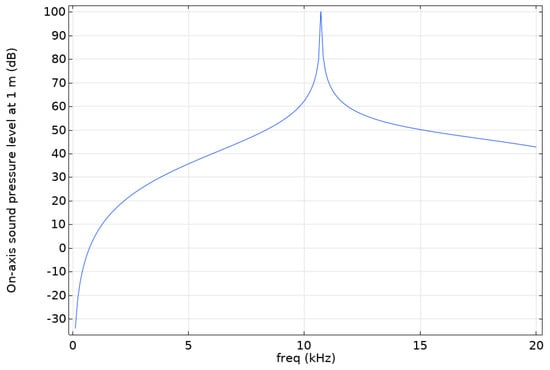
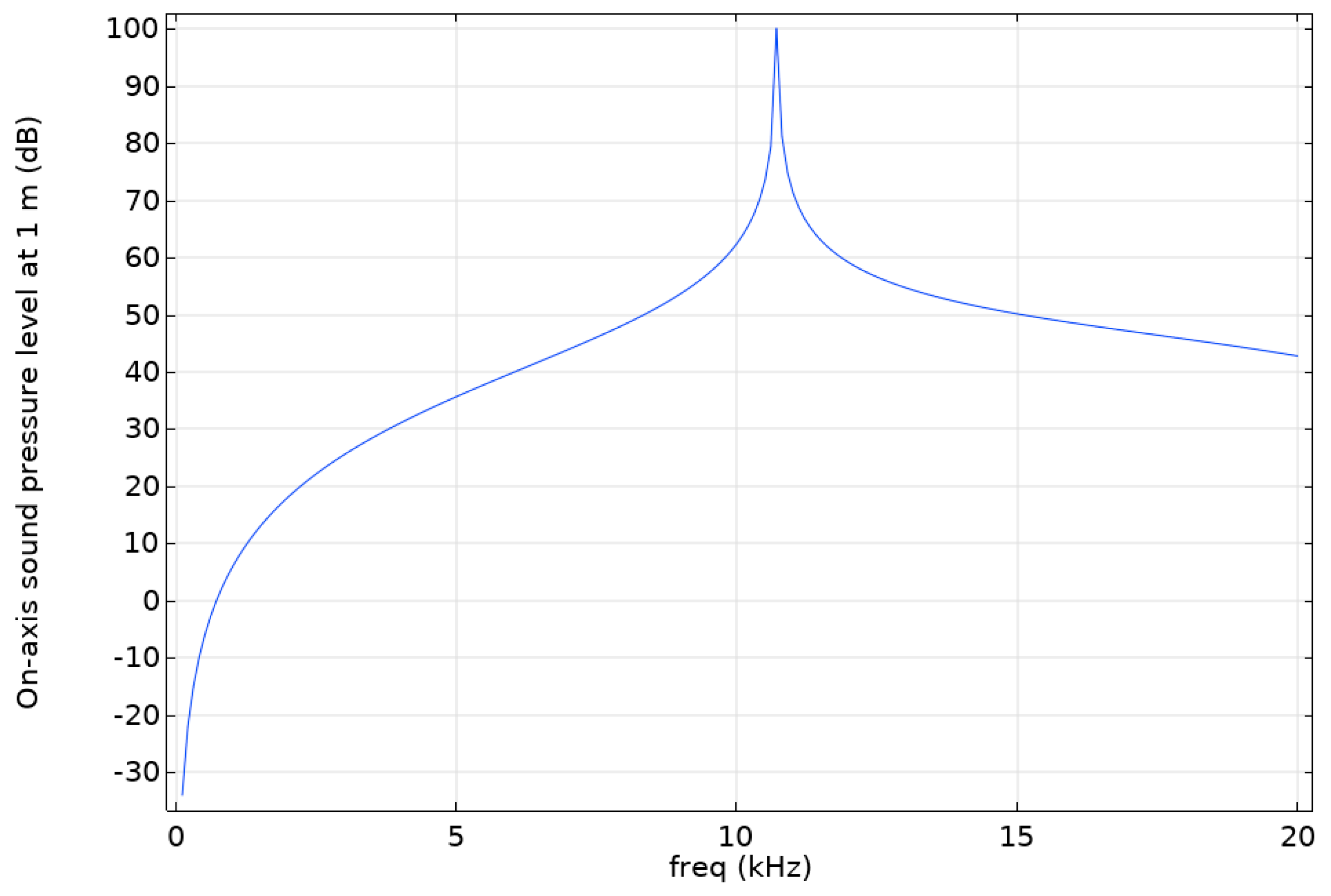
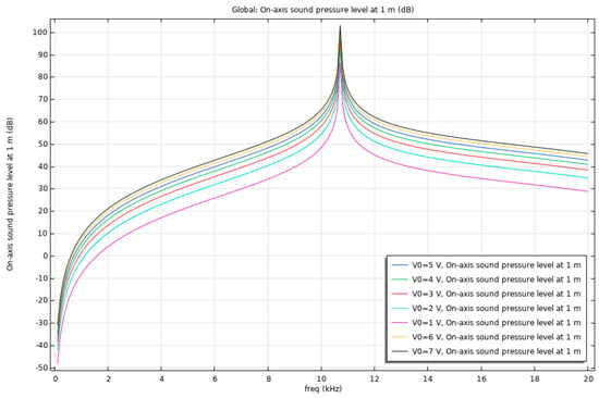
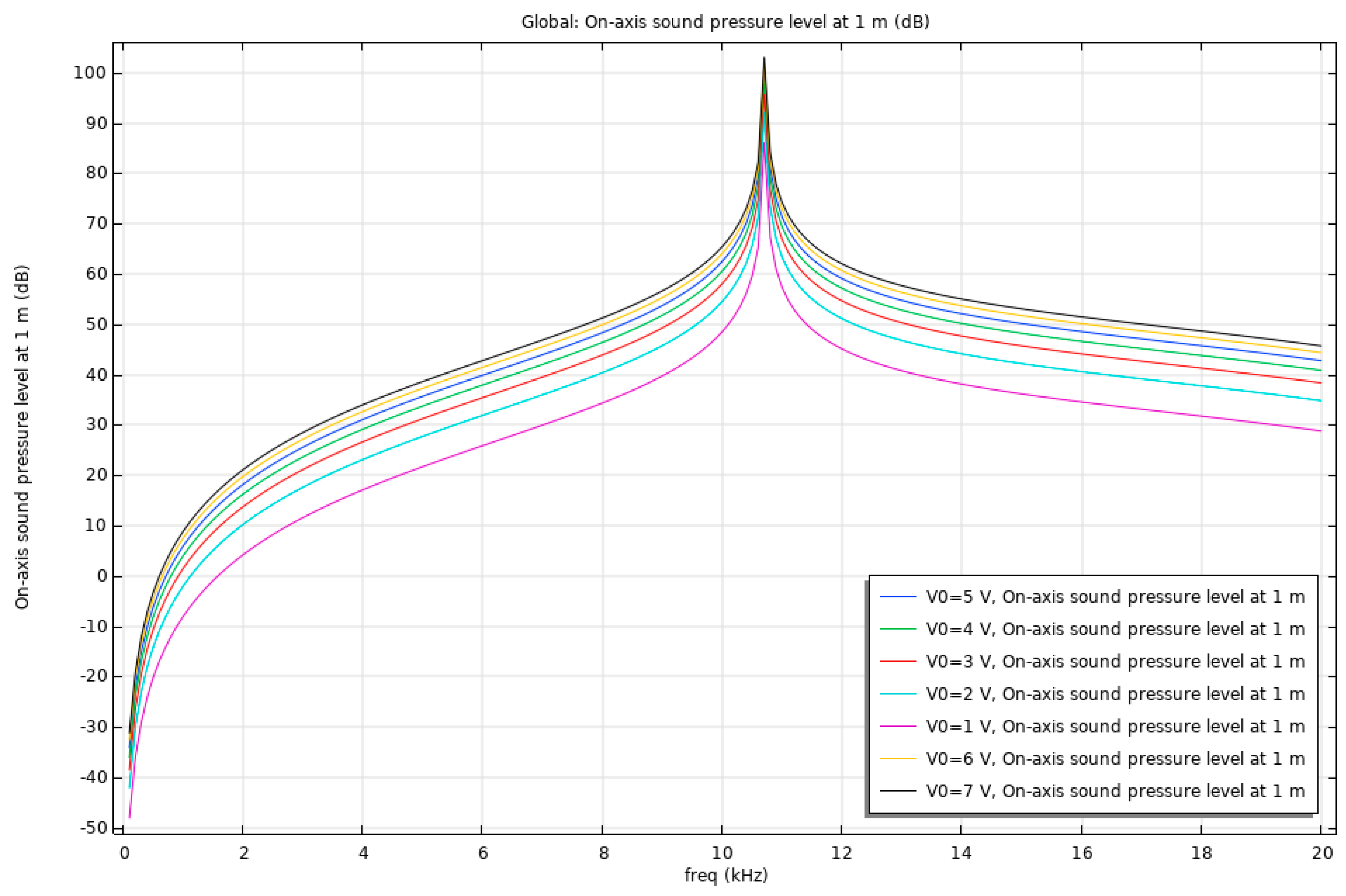
Figure 2 presents the on-axis sound pressure level modeled with the use of FEM, 1 m in front of the transducer over the investigated frequency range. The complete geometric configuration, including all dimensional specifications of the piezoelectric disk, brass membrane, and surrounding air domain, is documented in Appendix B, Table A2. A depiction of this configuration is presented in Figure 1. This configuration is adopted as the reference model for the vibro-acoustic analysis and serves as the baseline for all subsequent numerical modeling and parametric investigations presented in Section 3. The response exhibits a pronounced resonance at approximately 10.7 kHz, which dominates the on-axis radiation. Outside this region, the sound pressure level decreases gradually with frequency. This resonance is attributed to the acoustic behavior of the transducer and defines its primary operating region.
Figure 2.
On axis sound pressure level 1 m in front of the transducer.
3.2. Pressure Distribution
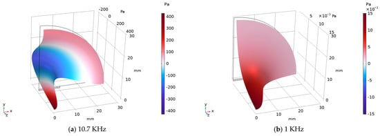
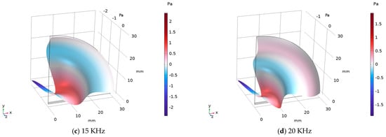
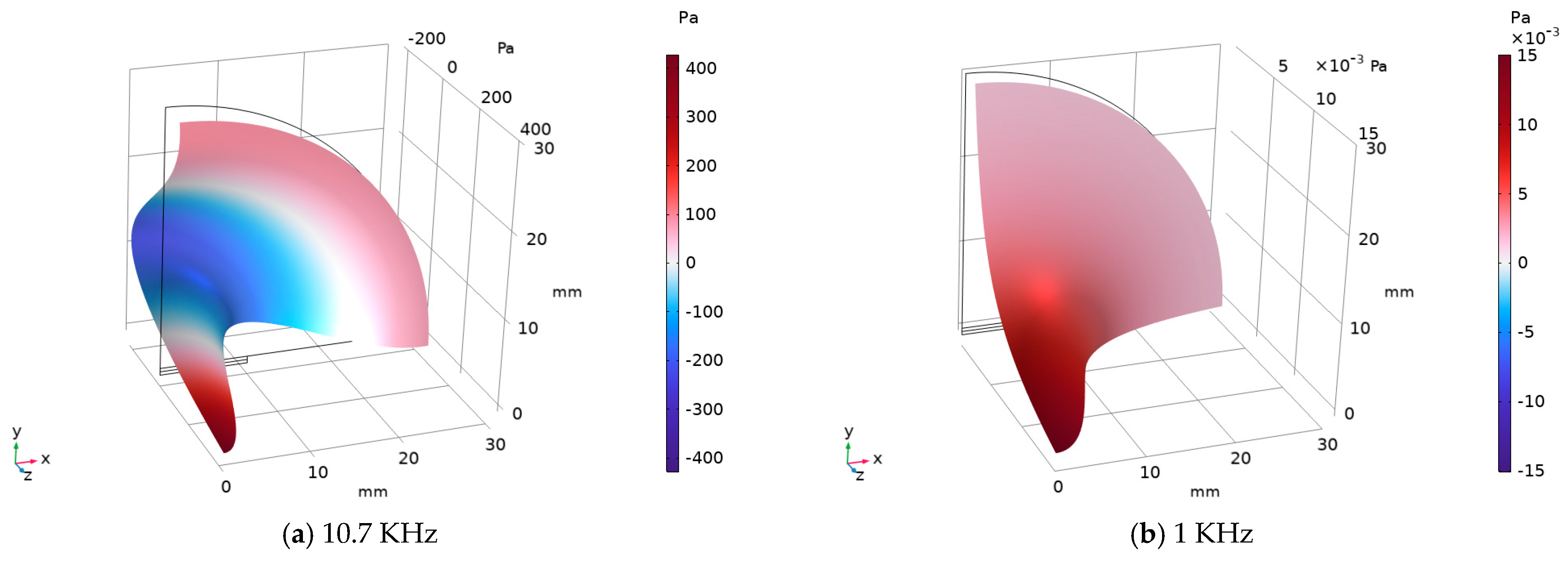
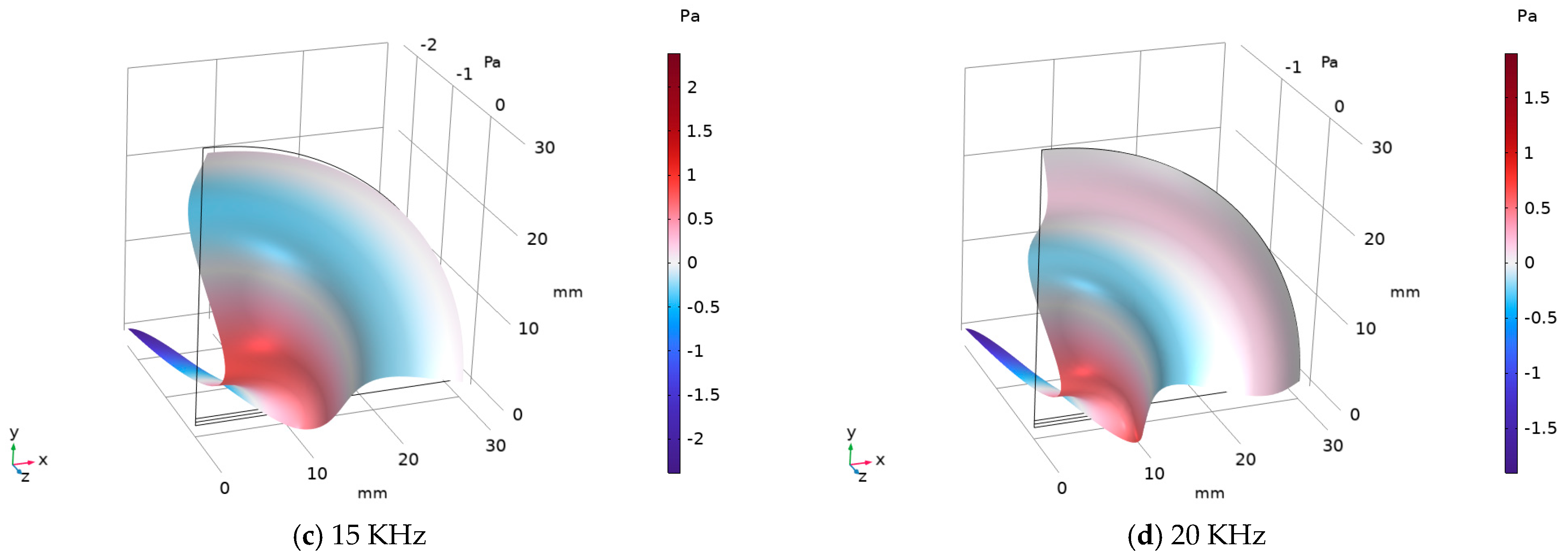
The pressure distribution (surface and height plot) is presented in Figure 3 for different selected frequencies (frequencies selected to span the frequency spectrum under consideration). The complete geometric configuration, similar as before, is documented in Appendix B, Table A2. Figure 3a presents the pressure distribution in the case of the resonance frequency. A marked increase in pressure magnitude is observed at resonance compared to off-resonant frequencies. In Figure 3, the axes are scaled non-uniformly to improve the visual representation of the pressure distributions.
Figure 3.
Surface and height plot of the pressure distribution for different frequencies. (a) presents the pressure distribution in the case of the resonance frequency. (b–d) present the pressure distributions for the frequencies 1, 15 and 20 KHz, respectively. The axes are scaled non-uniformly to improve the visual representation of the pressure distributions.
3.3. Displacement of the Membrane
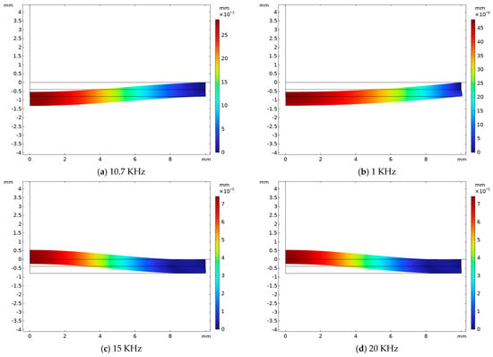
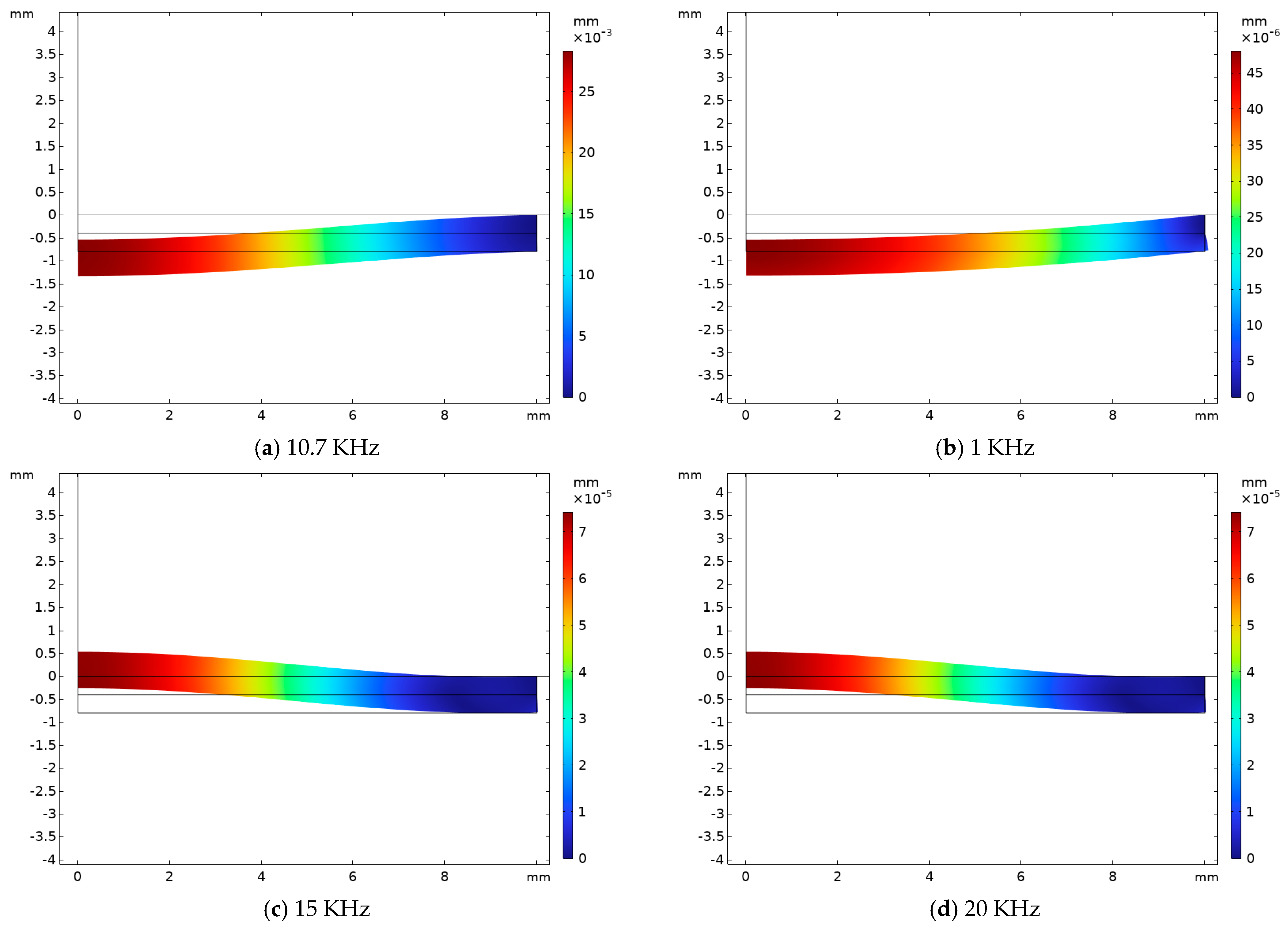
The membrane displacement is shown in Figure 4 for several selected frequencies. In particular, Figure 4a depicts the displacement profile at the resonance frequency. At resonance, the displacement amplitude is significantly higher than at off-resonant frequencies, indicating efficient electromechanical coupling. Away from resonance, the membrane response becomes more attenuated.
Figure 4.
Displacement of the membrane for different frequencies. (a) presents the displacement of the membrane in the case of the resonance frequency. (b–d) present the displacements of the membrane for the frequencies 1, 15 and 20 KHz, respectively. The axes are scaled non-uniformly to improve the visual representation of the displacement distributions.
3.4. Sound Pressure Level (3D)
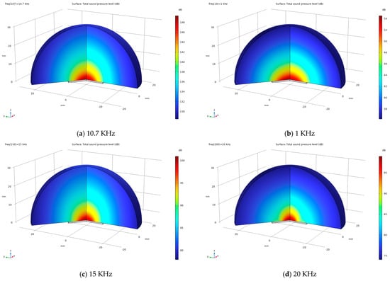
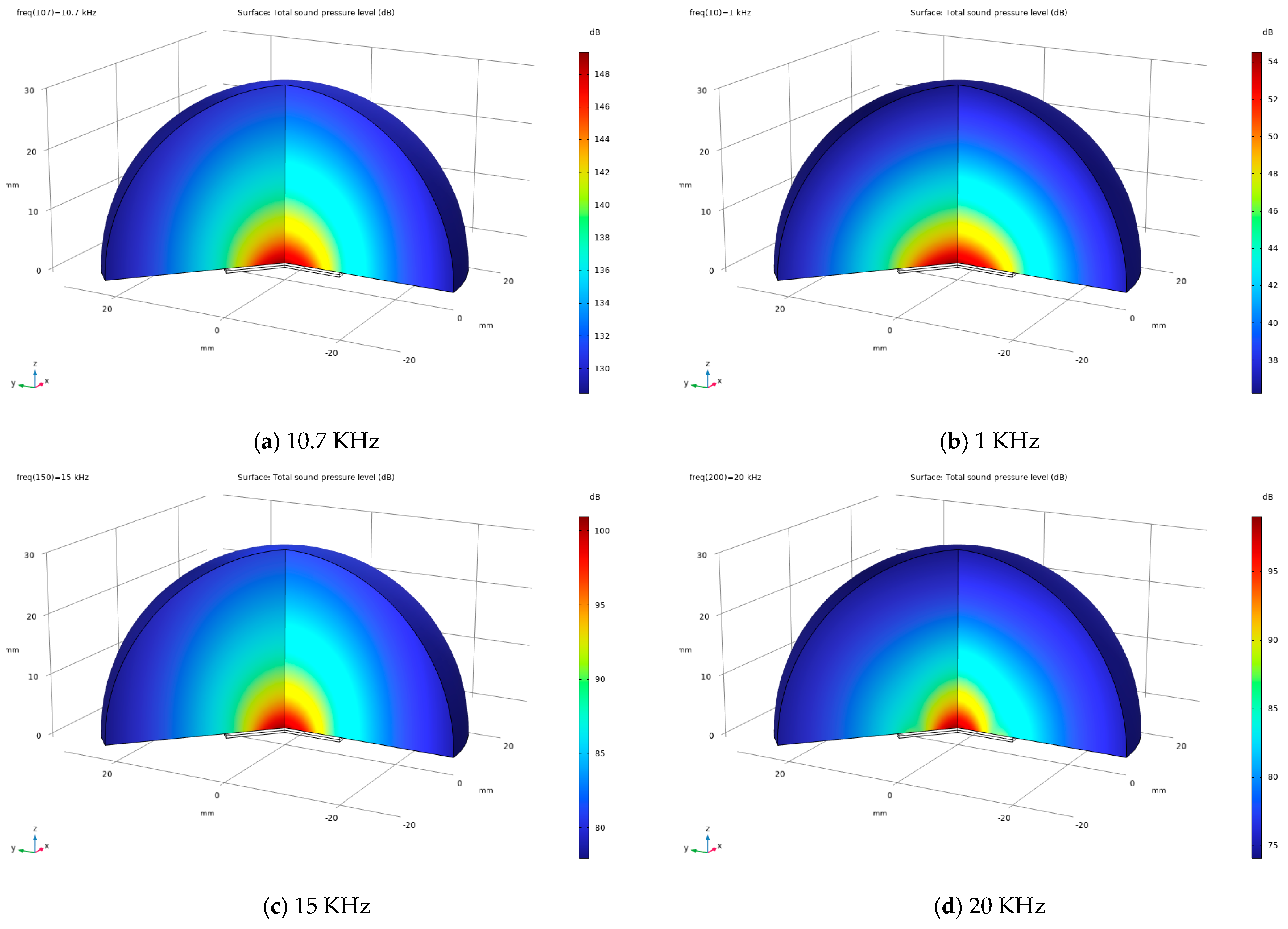
The three-dimensional sound pressure level (SPL) distribution is presented in Figure 5 for different selected frequencies. Figure 5a shows the SPL distribution at the resonance frequency. A significant increase in SPL magnitude is observed at resonance compared to off-resonant frequencies, indicating enhanced acoustic radiation. The maximum SPL values are concentrated in the region directly in front of the speaker, forming a clear directional radiation pattern. At higher frequencies away from resonance, the SPL distribution exhibits lower magnitudes and a more directional spatial pattern, reflecting the reduced vibration amplitude of the piezoelectric diaphragm.
Figure 5.
Three-dimensional sound pressure level (SPL) distribution for different frequencies. (a) presents the SPL distribution at the resonance frequency. (b–d) present the SPL distributions for the frequencies 1, 15 and 20 KHz, respectively. The axes are scaled non-uniformly to improve the visual representation of the SPL distributions.
3.5. Polar Plots of the Exterior-Field (Sound Pressure Level at 1 m)
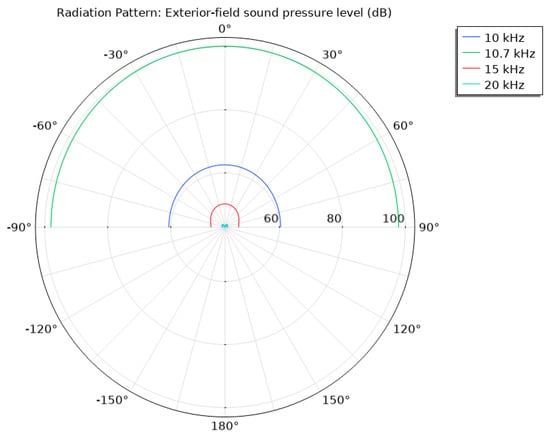
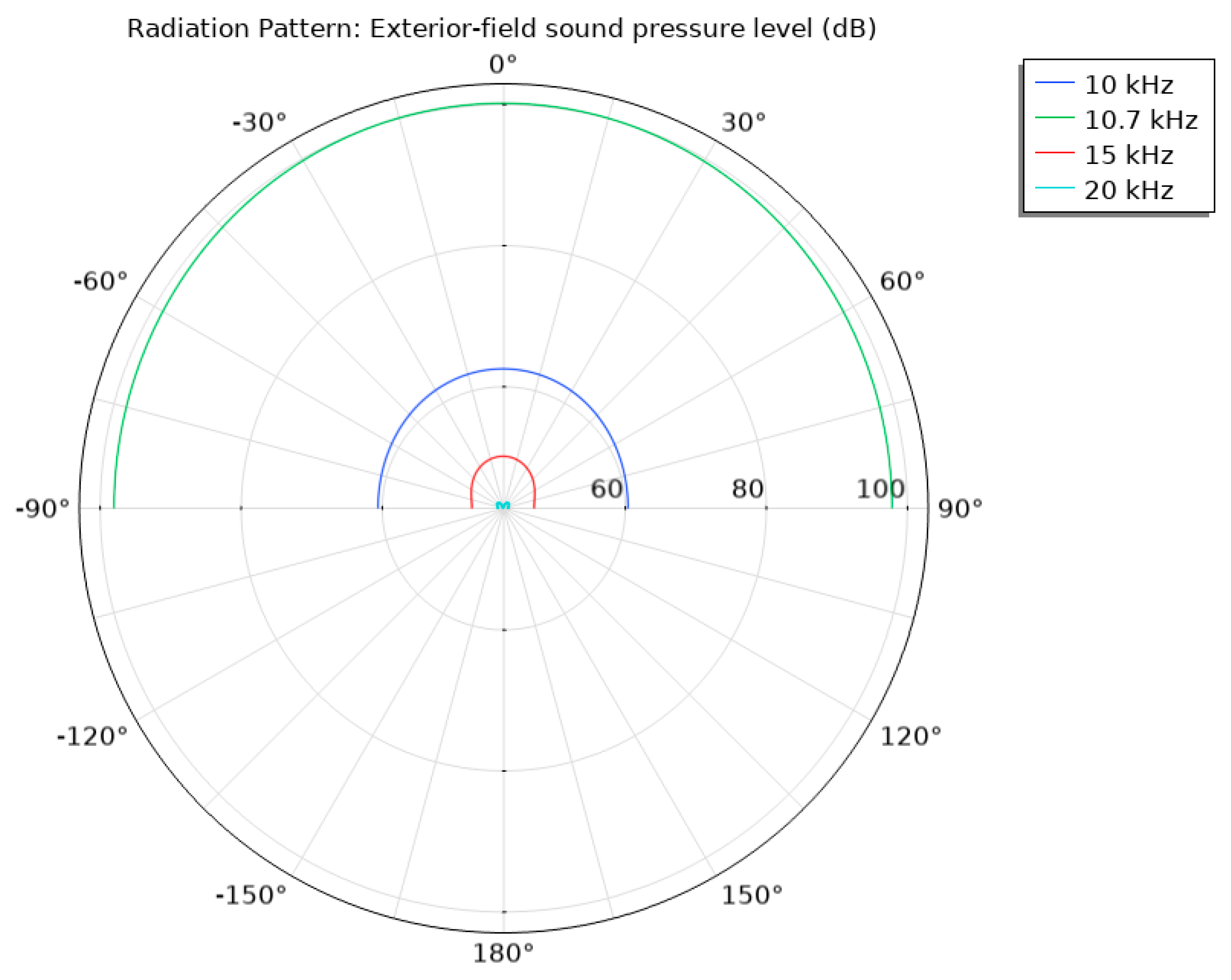
Figure 6 shows polar plots of the exterior acoustic field, expressed as sound pressure level (SPL) at 1 m, for excitation frequencies of 10 kHz, 15 kHz, 20 kHz, and the resonance frequency at 10.7 kHz. Although simulations were performed at 1 kHz, this case is not presented because the corresponding SPL variation is too small to be clearly resolved in the polar representation; therefore, a frequency of 10 kHz is presented instead for clarity. At 10.7 kHz, the radiation pattern remains nearly omnidirectional, consistent with the acoustic wavelength being larger than the characteristic speaker dimensions. With increasing frequency, the angular variation in SPL becomes more pronounced, indicating increased acoustic directivity. Overall, the results illustrate the frequency-dependent evolution of the exterior acoustic field and its dependence on excitation frequency.
Figure 6.
A polar plot of the exterior-field sound pressure level at 1 m. The 0 degree axis coincides with the +z direction of the rz-plane in the 2D axisymmetric model.
3.6. Parametric Study on the Effect of Brass Membrane Thickness (Resonance Frequency, SPL)
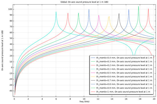
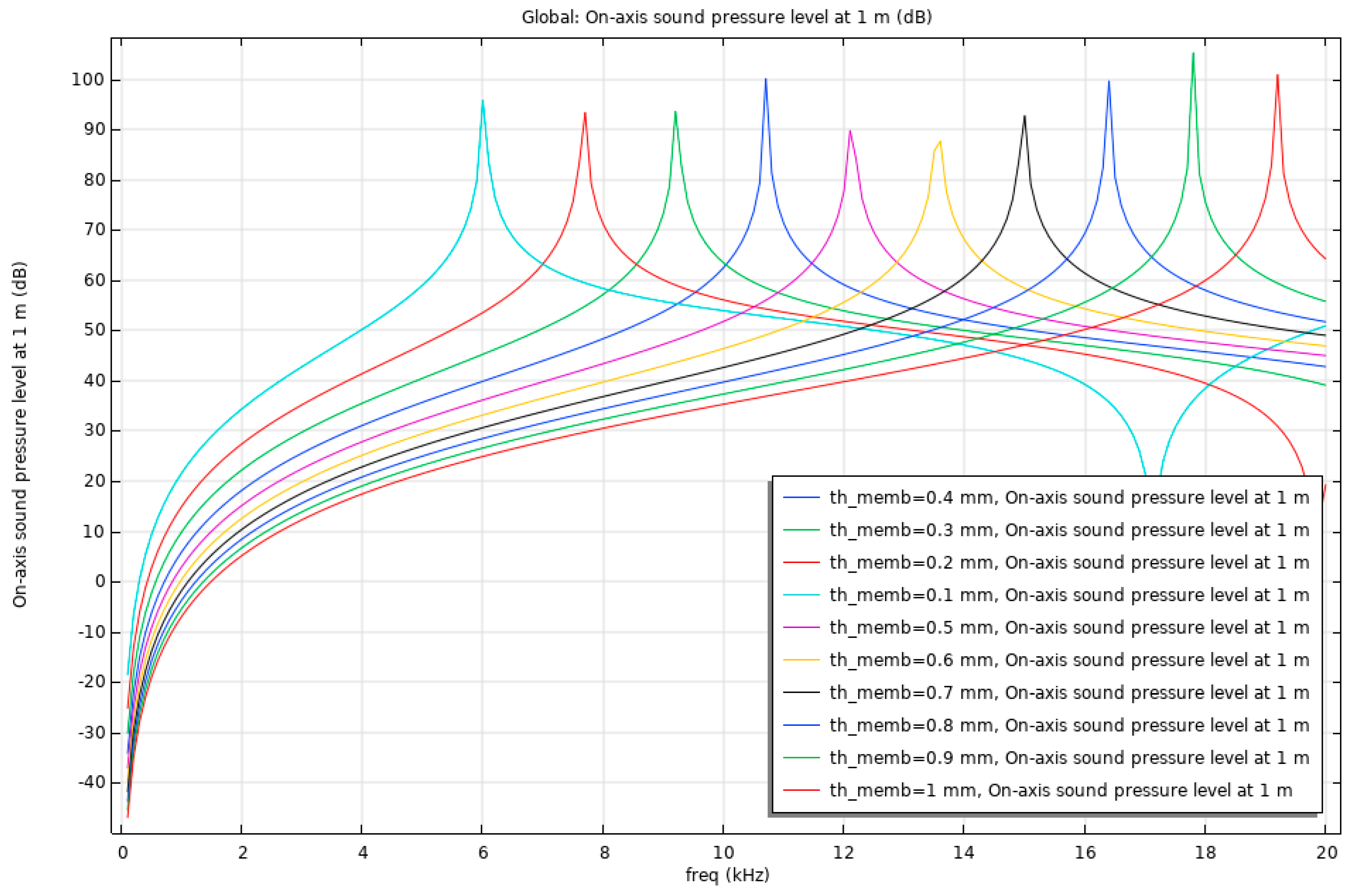
Figure 7 illustrates the variation in the resonance frequency and SPL with changes in the brass membrane thickness of the piezoelectric speaker. The results indicate that increasing the membrane thickness leads to a noticeable shift in the resonance frequency, primarily due to the increased structural stiffness of the brass layer. Thinner membranes exhibit lower stiffness, resulting in lower resonance frequencies, whereas thicker membranes tend to shift the resonance toward higher values. These variations should be interpreted relative to the reference configuration employing a 0.4 mm thick brass membrane, for which a dominant resonance at approximately 10.7 kHz was identified in the preceding subsections (e.g., Figure 2). This trend demonstrates a clear thickness-dependent behavior of the vibro-acoustic response. The finite element results suggest that membrane thickness is a critical design parameter for tuning the resonance characteristics of piezoelectric speakers.
Figure 7.
Resonance frequency and SPL as a function of brass membrane thickness.
In contrast, the sound pressure level shows no remarkable variation across the investigated range of brass membrane thicknesses. The SPL values remain relatively consistent despite changes in membrane thickness, indicating that thickness predominantly affects the dynamic characteristics of the structure rather than the acoustic output amplitude. This suggests that, within the studied parameter range, modifying the brass membrane thickness can be effectively used to tailor resonance frequency without significantly influencing SPL performance. These findings provide useful insight for optimizing membrane geometry to achieve desired acoustic performance.
3.7. Parametric Study on the Effect of Piezoelectric Disc Thickness (Resonance Frequency, SPL)
The variation in resonance frequency and SPL with changes in the thickness of the piezoelectric disc is presented in Figure 8. The observed trends should be interpreted relative to the reference configuration, which exhibits a dominant resonance at approximately 10.7 kHz, as established in the preceding subsections. The results demonstrate that modifying the piezoelectric disc thickness significantly influences both the resonance behavior and the acoustic output of the speaker, owing to changes in the electromechanical coupling efficiency and the effective stiffness of the active layer.
Figure 8.
Resonance frequency and SPL as a function of piezoelectric disc thickness.
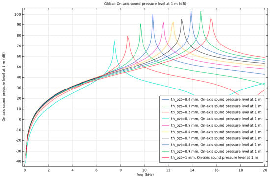
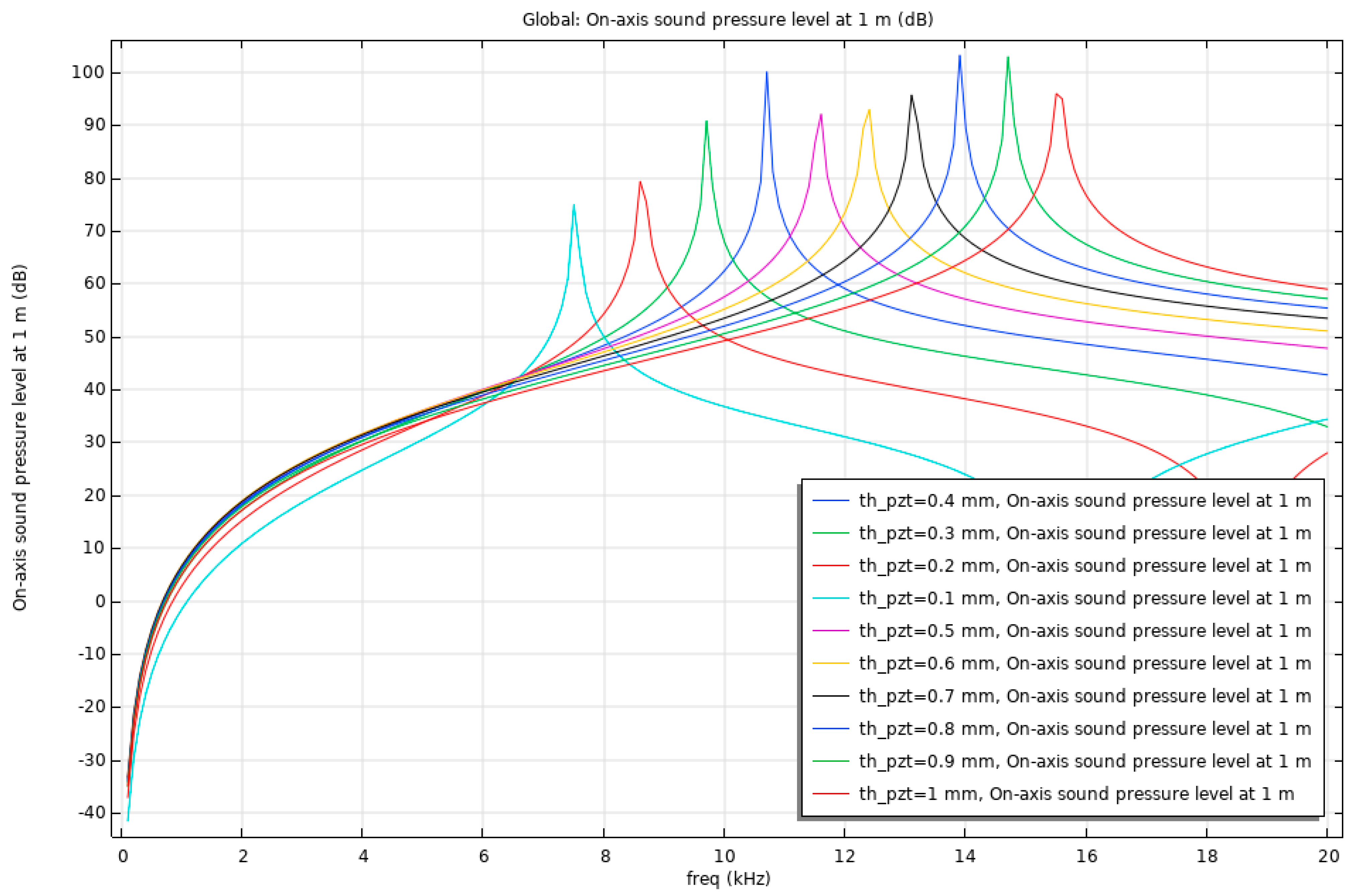
A decrease in piezoelectric disc thickness leads to a reduction in both resonance frequency and SPL, indicating diminished actuation capability and lower energy transfer to the surrounding air. In contrast, increasing the disc thickness shifts the resonance toward higher frequencies and results in a noticeable enhancement of SPL, reflecting improved electromechanical excitation and stronger structural–acoustic coupling. These trends highlight the strong sensitivity of both resonance frequency and SPL to the geometric properties of the piezoelectric disc. Consequently, piezoelectric disc thickness emerges as a critical design parameter for simultaneously tuning the resonance characteristics and acoustic output of piezoelectric speakers.
3.8. Parametric Study on the Effect of Piezoelectric Disc and Brass Membrane Radius (Resonance Frequency, SPL)
In Figure 9, the influence of variations in the piezoelectric disc and brass membrane radius on the resonance frequency and SPL of the piezoelectric speaker is illustrated. The results are presented relative to the reference configuration, in which both the piezoelectric disc and the brass membrane share an identical radius of 10 mm, yielding a dominant resonance at approximately 10.7 kHz as discussed in earlier subsections. In the present parametric study, the radius of the piezoelectric disc and the brass membrane is varied simultaneously and by the same amount in each case, ensuring consistent geometric coupling between the active and passive layers.
Figure 9.
Resonance frequency and SPL as a function of piezoelectric disc and brass membrane radius.
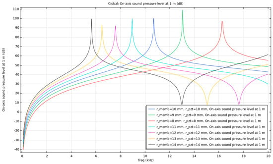
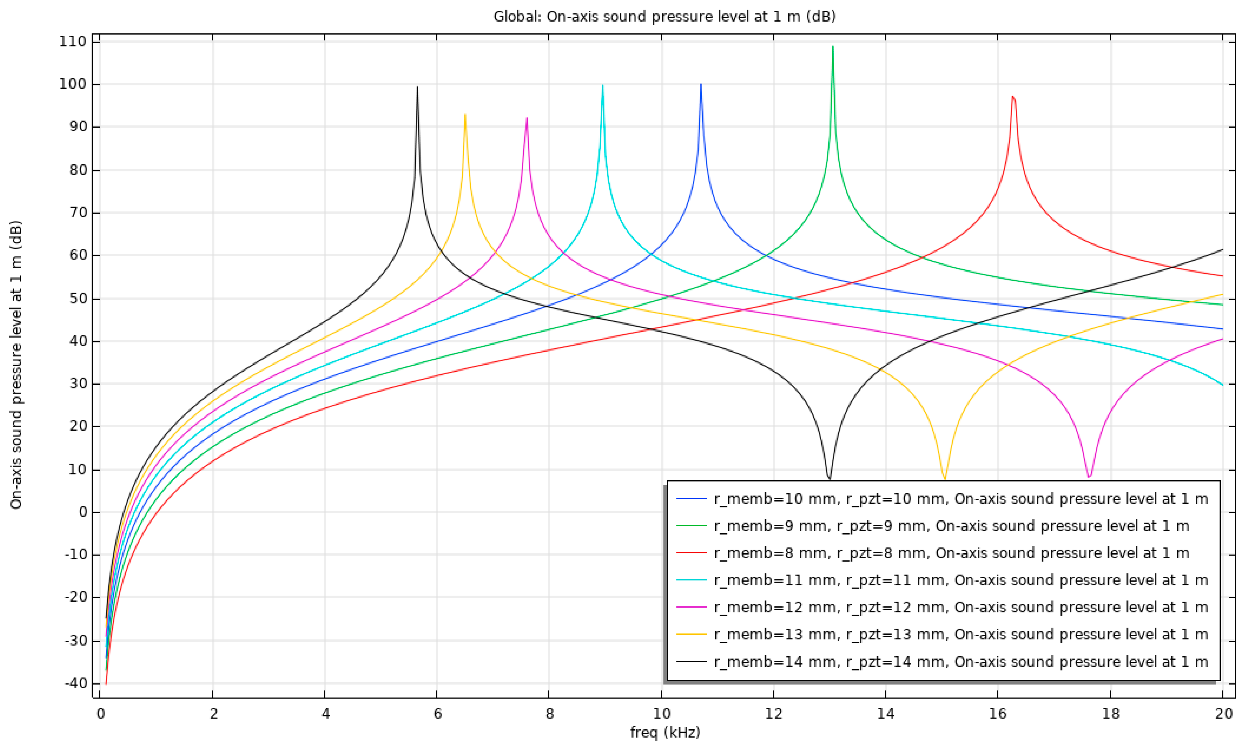
The results indicate that increasing the radius leads to a reduction in the resonance frequency, while the SPLs remain fairly similar across the investigated configurations. This behavior can be attributed to the enlarged effective vibrating area and increased mass participation, which collectively reduce the system’s natural frequency without significantly altering the acoustic radiation amplitude. Conversely, decreasing the radius shifts the resonance toward higher frequencies, again with SPL values remaining largely unchanged. These trends highlight the strong dependence of resonance frequency, but comparatively weak sensitivity of SPL, on the lateral geometry of the coupled piezoelectric disc and brass membrane. Overall, the findings demonstrate that careful optimization of the disc and membrane radius is essential for tailoring the vibro-acoustic performance of piezoelectric speakers.
3.9. Parametric Study on the Effect of Voltage (SPL, Resonance Frequency)
Finally, Figure 10 illustrates the effect of the applied excitation voltage on the resonance frequency and SPL of the piezoelectric speaker. The results demonstrate that variations in the excitation voltage do not lead to any noticeable change in the resonance frequency, which remains constant across the investigated voltage range. This behavior is expected, as the structural and material properties of the system are unchanged and the analysis is conducted within the linear operating regime of the piezoelectric material.
Figure 10.
Resonance frequency and SPL as a function of applied voltage.
In contrast, the sound pressure level exhibits a voltage-dependent response. At lower excitation voltages, a slight reduction in SPL is observed, corresponding to a reduced vibration amplitude of the radiating structure. Conversely, increasing the applied voltage results in a modest increase in SPL, reflecting the enhanced electromechanical excitation and greater acoustic radiation. These changes in SPL are relatively small, indicating a near-linear relationship between input voltage and acoustic output within the studied range. Overall, the results confirm that excitation voltage primarily governs the amplitude of the acoustic response, while the resonance frequency remains unaffected.
4. Discussion
The numerical results presented in Section 3 reveal consistent and physically interpretable tendencies in the vibro-acoustic response of the piezoelectric speaker. Rather than representing isolated numerical outcomes, the parametric curves exhibit systematic monotonic behaviors that can be directly linked to classical vibration theory and electromechanical coupling principles. The discussion below analyzes these tendencies in terms of stiffness, effective mass participation, and actuation efficiency, thereby clarifying the physical mechanisms governing the observed trends.
4.1. Influence of Brass Membrane Thickness: Stiffness-Dominated Resonance Tuning
The resonance-frequency curve associated with brass membrane thickness exhibits a clear monotonic increase as thickness increases (Figure 7). This tendency is consistent with classical plate theory, where the bending stiffness scales strongly with thickness. An increase in flexural rigidity elevates the structural natural frequency, resulting in the observed upward resonance shift. Similar stiffness-controlled frequency behavior has been reported in studies of piezoelectric diaphragms and panel-type radiators [30,31].
Importantly, the SPL curve corresponding to membrane thickness remains nearly flat across the investigated range. This weak sensitivity indicates that moderate variations in passive-layer stiffness do not significantly alter acoustic radiation efficiency. Since the mode shape remains largely axisymmetric and the effective radiating area is unchanged, the acoustic output amplitude is only marginally affected. Experimental observations for circular piezoelectric diaphragms similarly report that SPL correlates more strongly with displacement amplitude and modal characteristics than with passive-layer thickness alone [32].
Therefore, the parametric tendency extracted from Figure 7 can be summarized as follows: brass membrane thickness acts primarily as a resonance-frequency tuning parameter with limited influence on the SPL. This distinction is important for design optimization, as it enables frequency adjustment without substantial acoustic output degradation.
4.2. Influence of Piezoelectric Disc Thickness: Coupled Stiffness–Actuation Effect
In contrast to the passive brass layer, the piezoelectric disc thickness influences both resonance frequency and SPL in a strongly monotonic manner (Figure 8). The resonance-frequency curve increases with thickness, reflecting enhanced structural stiffness. Simultaneously, the SPL curve also increases, indicating improved electromechanical coupling and higher actuation force.
This dual tendency arises from the active role of the piezoelectric layer. Increasing its thickness not only modifies the structural rigidity but also enhances the electric-field-induced strain energy, thereby increasing vibration amplitude and acoustic radiation. Similar coupled effects have been reported in piezoelectric MEMS loudspeakers and thin-film transducers, where thicker active layers produce stronger acoustic output while shifting resonance frequencies [31,33].
The slope of the SPL curve demonstrates a clear positive correlation between piezoelectric thickness and acoustic output, confirming that this parameter directly governs electromechanical energy conversion efficiency. Conversely, reducing thickness weakens actuation capability, leading to simultaneous reductions in both resonance frequency and SPL.
Thus, the extracted tendency is fundamentally different from that of the brass membrane: piezoelectric disc thickness serves as a simultaneous resonance and SPL control parameter, making it a critical variable in compact speaker design.
4.3. Influence of Radius: Mass Participation and Frequency Scaling
The parametric curves associated with radius variation (Figure 9) display a monotonic decrease in resonance frequency with increasing radius. This inverse relationship reflects increased effective mass participation and reduced stiffness per unit area as the vibrating surface expands. Analytical and experimental studies of circular diaphragms similarly report this inverse scaling between lateral dimension and natural frequency [32].
Despite the pronounced frequency shift, the SPL curve remains comparatively insensitive to radius changes within the investigated range. This suggests that although the dynamic characteristics of the structure are modified, the overall radiation efficiency is not significantly altered because the increase in radiating area compensates for changes in displacement amplitude. Reviews of piezoelectric MEMS speakers likewise identify diaphragm radius as a dominant parameter for resonance placement rather than SPL enhancement [31].
The tendency extracted here is therefore clear: lateral geometry is an effective tool for frequency positioning without strong SPL penalty, offering an additional degree of freedom in resonance tuning.
4.4. Influence of Excitation Voltage: Linear Amplitude Scaling
The voltage parametric curves (Figure 10) show invariance of resonance frequency and near-linear scaling of SPL with excitation amplitude. The flat resonance-frequency curve confirms that, within the linear regime, natural frequencies depend exclusively on material and geometric properties and remain unaffected by drive level.
The SPL curve exhibits proportional growth with voltage, reflecting linear electromechanical coupling. Similar voltage-independent resonance behavior combined with amplitude scaling has been reported in experimental and numerical investigations of piezoelectric MEMS speakers [34]. The absence of nonlinear frequency shift further validates that the simulations remain within the small-deformation regime assumed in the governing equations.
This tendency confirms that voltage acts purely as an output amplitude control parameter and not as a structural tuning mechanism.
4.5. Synthesis of Parametric Tendencies
Collectively, the parametric curves reveal three clearly distinguishable behavioral categories:
- Stiffness-dominated parameters (brass thickness) → resonance shift, negligible SPL variation.
- Coupled stiffness–actuation parameters (piezoelectric thickness) → simultaneous resonance and SPL modification.
- Mass-scaling parameters (radius) → inverse resonance scaling, weak SPL sensitivity.
- Electrical excitation parameters (voltage) → amplitude scaling only.
This structured classification provides a deeper interpretation of the numerical results and establishes a coherent framework for geometry-driven optimization. The observed trends are consistent with broader finite element and experimental investigations of piezoelectric speakers and MEMS transducers [30], while the present study contributes a unified and comparative mapping of geometric design variables to vibro-acoustic performance indicators within a single multiphysics model.
4.6. Analytical Validation
To provide analytical support for the numerical results, the vibration behavior of the structure is interpreted using classical thin circular plate theory for clamped diaphragms. Within this framework, the fundamental resonance frequency follows the well-established scaling law , indicating that the dynamic response is governed by the balance between bending stiffness and inertial effects.
The trends obtained from the finite element simulations are fully consistent with this theoretical prediction. In particular, an increase in diaphragm or piezoelectric layer thickness leads to an increase in resonance frequency due to enhanced bending stiffness, whereas an increase in the effective radius results in a pronounced decrease in resonance frequency due to the quadratic dependence on the characteristic length scale. These results directly reflect the governing physics of plate vibration and confirm the expected stiffness–mass-controlled behavior of the system.
Although a closed-form analytical solution for the fully coupled piezoelectric–structural–acoustic system is not available, the agreement in scaling behavior between the numerical model and classical plate theory provides strong physical validation of the simulation framework. The analytical model is inherently simplified, as it neglects electromechanical coupling, damping, and acoustic loading effects; however, it accurately captures the dominant structural mechanics that govern the resonance characteristics of the device.
4.7. Limitations and Future Studies
A primary limitation of the present study is that the numerical investigation was conducted using a single piezoceramic material (PZT-5H), selected intentionally to isolate and systematically evaluate the influence of geometric parameters on vibro-acoustic performance. This approach allows the identification of clear dimension-dependent trends while minimizing the confounding influence of material variability. However, it does not account for potential differences associated with alternative piezoelectric materials that may exhibit different electromechanical coupling coefficients, dielectric properties, and elastic constants. Materials with stronger coupling factors could potentially generate larger diaphragm displacements and consequently higher sound pressure levels (SPL), whereas materials with lower coupling efficiency would be expected to reduce acoustic output. In contrast, the influence of material substitution on resonance frequency is expected to remain secondary compared with the dominant effects of geometric stiffness and mass distribution.
Another limitation of the present investigation is the absence of direct experimental validation of the numerical predictions. Although the developed finite element model incorporates coupled electromechanical–acoustic physics, established piezoelectric constitutive relations, and a physically consistent representation of the structural and acoustic domains, its predictive capability has not yet been verified through prototype-level measurements for multiple geometric configurations. Consequently, the results presented in this work should primarily be interpreted as systematic numerical trend analyses and comparative design insights rather than fully validated absolute performance predictions.
The present study was intentionally conceived as the first stage of a broader research effort aimed at the systematic design and optimization of compact piezoelectric speaker systems. Within this research framework, the numerical model serves as a design-screening and parametric exploration tool, enabling the identification of promising geometric configurations prior to prototype fabrication. Conducting experimental validation across the full set of investigated geometric variations would require the fabrication and acoustic characterization of a large number of prototypes with precisely controlled parameters, which would be both time-consuming and resource-intensive. By first establishing the numerical trends, the present work enables a more targeted and efficient experimental campaign focusing on the most promising configurations.
Future research will therefore focus on experimental validation of the numerical predictions presented in this study. Selected designs identified through the present parametric analysis will be fabricated and characterized using controlled acoustic measurements in order to assess resonance behavior, diaphragm vibration characteristics, and sound pressure level output. Such experiments will allow direct comparison between measured data and model predictions, thereby enabling further refinement of the computational framework and providing a comprehensive validation of the identified vibro-acoustic trends.
Despite these limitations, the developed computational framework remains sufficiently general and flexible to accommodate alternative materials, boundary conditions, and geometric configurations. As such, it provides a structured foundation for future investigations aimed at extending the model, incorporating experimentally validated parameters, and developing optimized piezoelectric acoustic devices with improved vibro-acoustic performance.
5. Conclusions
In this study, a coupled electromechanical–acoustic finite element framework was employed to systematically investigate the influence of geometric parameters on piezoelectric speaker performance. The model incorporated piezoelectric constitutive behavior, structural dynamics, and an acoustic domain to simulate vibration and sound radiation. Parametric analyses were conducted by varying diaphragm thickness and radius, as well as applied voltage, to quantify their effects on the resonance frequency and sound pressure level (SPL).
The results demonstrate that the vibro-acoustic performance of piezoelectric speakers is strongly governed by geometric parameters, including the thickness and radius of both the brass membrane and the piezoelectric disc, while excitation voltage primarily controls acoustic amplitude. Key findings reveal that increasing the membrane thickness or disc radius shifts resonance toward higher or lower frequencies, respectively, whereas disc thickness simultaneously enhances the resonance frequency and SPL. The SPL shows limited sensitivity to passive membrane properties but scales with disc thickness and applied voltage, reflecting the critical role of electromechanical coupling in acoustic generation. These results advance the field by providing a systematic, quantitative framework linking geometric design parameters to both resonance behavior and acoustic output, going beyond prior studies that focused on isolated design aspects or experimental prototypes.
The implications of these findings are significant for the design and optimization of compact, high-performance piezoelectric speakers and MEMS acoustic devices. By strategically selecting membrane and disc dimensions, designers can precisely tune resonance frequencies and maximize SPLs without extensive trial-and-error experimentation. Beyond speaker design, the insights gained here can inform a broad range of applications involving piezoelectric energy transducers, ultrasonic actuators, and acoustic sensors, where geometric optimization is crucial for enhancing electromechanical efficiency and performance. Overall, this work provides a practical roadmap for leveraging structural geometry to achieve tailored acoustic responses in piezoelectric devices.
Author Contributions
Conceptualization, N.M.P.; methodology, N.M.P.; software, N.M.P.; validation, N.M.P. and G.E.S.; formal analysis, N.M.P.; investigation, N.M.P.; resources, N.M.P.; data curation, N.M.P.; writing—original draft preparation, N.M.P.; writing—review and editing, N.M.P.; visualization, N.M.P.; supervision, N.M.P.; project administration, N.M.P.; funding acquisition, N.M.P. and G.E.S. All authors have read and agreed to the published version of the manuscript.
Funding
Work supported by the Hellenic Foundation for Research and Innovation (H.F.R.I.), Project SCPVSA “Nonlinear shunt circuit piezoelectric vibration absorbers for structures and acoustics”, project ID: 26236 (3rd Call for Research Projects to Support Faculty Members).
Institutional Review Board Statement
Not applicable.
Data Availability Statement
Data is available from the corresponding author upon reasonable request.
Conflicts of Interest
The author declares no conflicts of interest.
Abbreviations
The following abbreviations are used in this manuscript:
| FEA | Finite Element Analysis |
| FEM | Finite Element Method |
| MEMS | Micro-Electro-Mechanical Systems |
| PML | Perfectly Matched Layer |
| PVDF | Polyvinylidene Fluoride |
| PZT | Lead Zirconate Titanate |
| SPL | Sound Pressure Level |
Appendix A
Table A1.
Material Properties of PZT-5H.
Appendix B
Table A2.
Geometric Configuration and details of the Model Components.
References
- Singh, N.; Mahato, D.K. Piezoelectric Materials: Design and Applications; CRC Press: Boca Raton, FL, USA, 2025. [Google Scholar]
- Sekhar, M.C.; Veena, E.; Kumar, N.S.; Naidu, K.C.B.; Mallikarjuna, A.; Basha, D.B. A review on piezoelectric materials and their applications. Cryst. Res. Technol. 2023, 58, 2200130. [Google Scholar] [CrossRef] [Scilit]
- Golea, D.G.; Ștefan Cozma, L. The Use of Piezoelectric Materials for the Purpose of Creating Infrasound and Ultrasound Sources for Terrorist Acts. Am. J. Mod. Phys. 2021, 10, 129. [Google Scholar] [CrossRef] [Scilit]
- Johnson, J.B.; Anderson, J.; Anthony, R.; Sciotto, M. Detecting geyser activity with infrasound. J. Volcanol. Geotherm. Res. 2013, 256, 105–117. [Google Scholar] [CrossRef] [Scilit]
- Tressler, J.F. Piezoelectric transducer designs for sonar applications. In Piezoelectric and Acoustic Materials for Transducer Applications; Springer: Berlin/Heidelberg, Germany, 2008; pp. 217–239. [Google Scholar]
- Yoneyama, M.; Fujimoto, J.i.; Kawamo, Y.; Sasabe, S. The audio spotlight: An application of nonlinear interaction of sound waves to a new type of loudspeaker design. J. Acoust. Soc. Am. 1983, 73, 1532–1536. [Google Scholar] [CrossRef] [Scilit]
- Jayachandran, V.; Meyer, N.; Westervelt, M.; Sun, J. Piezoelectrically driven speakers for active aircraft interior noise suppression. Appl. Acoust. 1999, 57, 263–277. [Google Scholar] [CrossRef] [Scilit]
- Lin, R.R.; Palazzolo, A.B.; Kascak, A.F.; Montague, G. Use of piezoelectric actuators in active vibration control of rotating machinery. Electro-Opt. Mater. Switch. Coat. Sens. Opt. Detect. 1990, 1307, 199–210. [Google Scholar] [CrossRef] [Scilit]
- Ingale, M.; Khot, U.P. Optimization of graphene-based speaker for hearing aids. J. Eng. Appl. Sci. 2025, 72, 201. [Google Scholar] [CrossRef] [Scilit]
- Papadakis, N.M.; Stavroulakis, G.E. Review of Acoustic Sources Alternatives to a Dodecahedron Speaker. Appl. Sci. 2019, 9, 3705. [Google Scholar] [CrossRef] [Scilit]
- Papadakis, N.M.; Stavroulakis, G.E. Low Cost Omnidirectional Sound Source Utilizing a Common Directional Loudspeaker for Impulse Response Measurements. Appl. Sci. 2018, 8, 1703. [Google Scholar] [CrossRef] [Scilit]
- Jaffe, W. Piezoelectric Ceramics; Academic Press: New York, NY, USA, 1971. [Google Scholar] [CrossRef] [Scilit]
- Bolzmacher, C.; Benbara, N.; Rebillat, M.; Mechbal, N. Piezoelectric transducer for low frequency sound generation on surface loudspeakers. In Proceedings of the IX ECCOMAS Thematic Conference on Smart Structures and Materials, Paris, France, 8–11 July 2019; pp. 1–10. [Google Scholar]
- Nguyen, K. In-Situ/Operando X-Ray Diffraction Applied to Advanced Functional Films and Devices. Ph.D. Thesis, Université Grenoble Alpes, Saint-Martin-d’Hères, France, 2023. [Google Scholar]
- Han, J.; Saravanapavanantham, M.; Chua, M.R.; Lang, J.H.; Bulović, V. A versatile acoustically active surface based on piezoelectric microstructures. Microsyst. Nanoeng. 2022, 8, 55. [Google Scholar] [CrossRef] [Scilit]
- Giampiccolo, R.; Bernardini, A.; Sarti, A. Wave digital models of piezoelectric transducers for audio applications. IEEE Sens. J. 2022, 23, 389–400. [Google Scholar] [CrossRef] [Scilit]
- Papadakis, N.M. Application of Finite Element Method for Estimation of Acoustic Parameters. Ph.D. Thesis, Technical Univeristy of Crete, Chania, Greece, 2018. [Google Scholar]
- Bhargava, A.; Shahab, S. Acoustic-electroelastic modeling of piezoelectric disks in high-intensity focused ultrasound power transfer systems. J. Intell. Mater. Syst. Struct. 2021, 32, 1215–1233. [Google Scholar] [CrossRef] [Scilit]
- Liechti, R. Development of a MEMS Loudspeaker with Optimized Performance. Ph.D. Thesis, Le Mans Université, Le Mans, France, 2022. [Google Scholar]
- Toth, F.; Hassanpour Guilvaiee, H.; Jank, G. Acoustics on small scales: Modelling viscous effects in MEMS devices. Elektrotech. Informationstech. 2021, 138, 155–161. [Google Scholar] [CrossRef] [Scilit]
- Baumann, P. Piezoelectric Buzzer. In Selected Sensor Circuits: From Data Sheet to Simulation; Springer: Berlin/Heidelberg, Germany, 2022; pp. 183–220. [Google Scholar]
- Sommerfeld, A. Die Greensche Funktion der Schwingungsgleichung. J.-Ber. Dtsch. Math.-Ver. 1912, 21, 309–353. [Google Scholar]
- Berenger, J.-P. A perfectly matched layer for the absorption of electromagnetic waves. J. Comput. Phys. 1994, 114, 185–200. [Google Scholar] [CrossRef] [Scilit]
- Liu, Q.-H.; Tao, J. The perfectly matched layer for acoustic waves in absorptive media. J. Acoust. Soc. Am. 1997, 102, 2072–2082. [Google Scholar] [CrossRef] [Scilit]
- Papadakis, N.M.; Stavroulakis, G.E. Finite Element Method for the Estimation of Insertion Loss of Noise Barriers: Comparison with Various Formulae (2D). Urban Sci. 2020, 4, 77. [Google Scholar] [CrossRef] [Scilit]
- Thompson, L.L. A review of finite-element methods for time-harmonic acoustics. J. Acoust. Soc. Am. 2006, 119, 1315–1330. [Google Scholar] [CrossRef] [Scilit]
- Shirron, J.J.; Babuška, I. A comparison of approximate boundary conditions and infinite element methods for exterior Helmholtz problems. Comput. Methods Appl. Mech. Eng. 1998, 164, 121–139. [Google Scholar] [CrossRef] [Scilit]
- Ihlenburg, F. Finite Element Analysis of Acoustic Scattering; Springer Science & Business Media: Berlin/Heidelberg, Germany, 2006; Volume 132. [Google Scholar]
- Papadakis, N.M.; Stavroulakis, G.E. Effect of Mesh Size for Modeling Impulse Responses of Acoustic Spaces via Finite Element Method in the Time Domain. In Proceedings of the Euronoise 2018, Crete, Greece, 27–31 May 2018. [Google Scholar]
- Huang, S.; Yang, Y.; Liu, S.; Chu, X. A large-diaphragm piezoelectric panel loudspeaker and its acoustic frequency response simulation method. Appl. Acoust. 2017, 125, 176–183. [Google Scholar] [CrossRef] [Scilit]
- Wang, H.; Ma, Y.; Zheng, Q.; Cao, K.; Lu, Y.; Xie, H. Review of recent development of MEMS speakers. Micromachines 2021, 12, 1257. [Google Scholar] [CrossRef] [Scilit] [PubMed]
- Chiang, H.-Y.; Huang, Y.-H. Resonance mode and sound pressure produced by circular diaphragms of electrostatic and piezoelectric speakers. Appl. Acoust. 2018, 129, 365–378. [Google Scholar] [CrossRef] [Scilit]
- Joshi, S.V.; Sadeghpour, S.; Kraft, M. Low-cost piezo-MEMS speaker technology. Micro Nano Eng. 2023, 19, 100213. [Google Scholar] [CrossRef] [Scilit]
- Wang, Q.; Ruan, T.; Xu, Q.; Hu, Z.; Yang, B.; You, M.; Lin, Z.; Liu, J. A piezoelectric MEMS speaker with a combined function of a silent alarm. Micromachines 2023, 14, 702. [Google Scholar] [CrossRef] [Scilit]
Disclaimer/Publisher’s Note: The statements, opinions and data contained in all publications are solely those of the individual author(s) and contributor(s) and not of MDPI and/or the editor(s). MDPI and/or the editor(s) disclaim responsibility for any injury to people or property resulting from any ideas, methods, instructions or products referred to in the content. |
© 2026 by the authors. Licensee MDPI, Basel, Switzerland. This article is an open access article distributed under the terms and conditions of the Creative Commons Attribution (CC BY) license.