


Abstract
Upper limb deficiencies can limit the range of tasks children can perform. Current prosthetics provide overall good performance to increase the activities that users can complete, but challenges remain. Body- or electrically powered prostheses struggle to restore the full range of motion needed for specific tasks. Currently, these systems do not allow for controlled hand closure or opening across all possible postures. A breathing-powered prototype named Airbender, which extracts energy from a breathing input by means of a Tesla turbine, provides the possibility of operation in any position. This paper introduces a novel design for a multi-finger actuated breathing-powered upper limb prosthetic concept and analyses its performance through a series of lab-based experiments. Results show that such a design could provide a fully controllable system. The final assembled design is capable of achieving full actuation under a flow rate of 340 Ls/min. The results obtained demonstrate that a functional multi-finger actuated breathing-powered upper limb prosthesis could be feasible and opens a path for future research in the field, with the ultimate goal of reducing the minimum flow rate required and actuation time to further improve its functionality.
1. Introduction
The world is designed to be navigated with our hands, making them essential for both power and precision tasks [1]. Their loss—whether from congenital conditions linked to genetics or environment, or acquired through trauma or illness—impairs daily function and causes emotional and physical distress, including phantom limb pain [2,3]. Prosthetic development is vital for restoring independence and improving quality of life. Congenital limb deficiencies occur in 5–9.7 per 10,000 births, with a 3:1 upper-to-lower limb ratio [4], and UL amputations in the US alone reach 185,000 annually [5]. Rates may be higher in lower-income regions, underscoring the global need for affordable, accessible upper-limb (UL) prostheses.
To address the challenges UL deficiencies pose—especially for children and adolescents—prosthetic devices have been developed in two main categories: active and passive. Active prostheses use motors, sensors, and microprocessors to mimic natural movements but are often heavy, complex, and maintenance-intensive [6]. Passive prostheses rely on user muscle power, lowering cost and complexity, but often limit motion, fine control, and comfort. The most common pediatric option is a body-powered (BP) device, which uses a harness to translate muscle contractions into movement. However, not all users can wear it, and extended use may cause skin irritation and fatigue [5].
Limitations of active and passive prostheses have led to research into alternative, non-invasive power sources. Breathing-powered systems have emerged as a promising solution, offering adaptability and practicality for children and adolescents. This concept was first introduced with “The Airbender” [7], a device powered by exhaling into a mouthpiece, removing the need for a harness and allowing free positioning of the prosthetic hand. A turbine converts air flow into mechanical energy, driving a transmission system that increases torque to actuate the index finger. This method enables intuitive, adjustable control through natural breathing, even in younger users. Users were able to operate this device without any meaningful training [8]. The same study mentioned that children with a limb difference found it comfortable to operate the device using breathing. All children in this study liked the concept and reported that the experiments and interaction with the device were fun and simple.
The Airbender used a four-stage gear transmission: three spur gear stages and a final worm drive for self-locking. The worm gear actuated a 6 cm index finger aligned to close against a fixed thumb. Two versions were tested: a ‘Fast’ setup (GR 225:1) with 3.42 N grip force in 1.05 s, and a ‘Slow’ version (GR 721:1) producing 10.93 N in 3.36 s. These performance levels are typical in pediatric prosthetics [9]. However, the design faced high friction losses and a major limitation — it enabled only single-finger actuation.
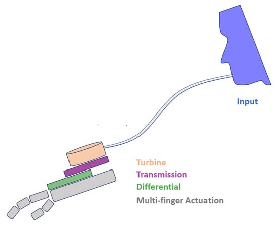
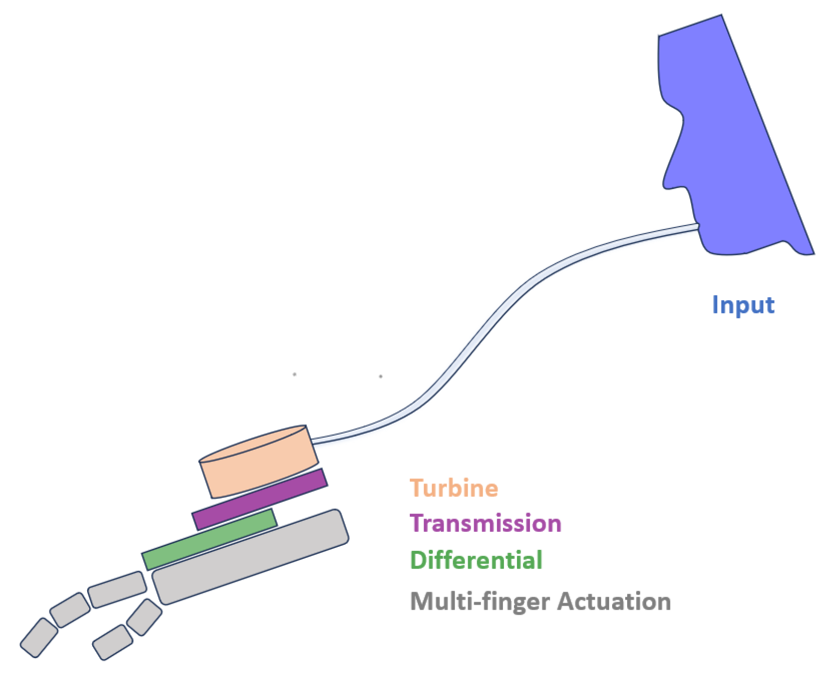
To address this, this paper proposes an alternative multi-finger actuation system with non-fixed finger joints. This would allow the user to grasp and manipulate objects with more ease and dexterity as well as augment the range of tasks that can be performed. Moreover, this paper explores an alternative transmission system from breathing input to finger actuation, aiming to reduce weight while achieving a higher system efficiency. The aim of this study is to introduce a novel design for a multi-finger actuated breathing-powered upper limb prosthesis and analyse its performance through a series of lab-based experiments. A schematic of the system’s layout and operation can be observed in Figure 1.
Figure 1.
Schematic diagram showing the different subsystems within the breathing-powered prosthesis, featuring a turbine, transmission and differential subsystems, and finally, the multi-finger actuation with non-fixed joints.
2. Materials and Methods
The methodology of this work consisted in developing prototypes for each of the four subsystems within the prosthesis: the turbine, the transmission, the differential, and the actuation. The design process started with identifying a suitable turbine that could efficiently extract energy from air flow rates (FRs) typical of children and adolescents to power the system. The characteristics and results of these were then used to design and optimise the following three subsystems, as shown in Figure 2.
Figure 2.
Flowchart showing the system layout. This report mainly focuses on the design of the three subsystems consisting of the turbine, transmission, and differential subsystem.
2.1. Turbine
Converting the user’s breathing input into mechanical power can be achieved with the use of a turbine. Multiple types of turbines exist, but for this specific scenario, where the air will have a high humidity and may likely be riddled with dust or debris, conventional bladed turbines may experience damage. Additionally, the nature of the prosthesis’ mechanism requires a bidirectional capability to achieve both Voluntary Opening or VO and Voluntary Closing or VC, which is not a characteristic of bladed turbines. On the other hand, a bladeless Tesla turbine (patented by Nikola Tesla in 1913 [10]) possesses a simpler design which does not require complex blade cross-sections, making it compact, affordable, and easy to maintain. The absence of blades allows it to maintain balance while in operation, which is crucial for biomedical applications where humans may carry them. These turbines can harness energy from various working fluids and possess a self-cleaning mechanism, reducing maintenance requirements throughout their lifespan [11]. One of the most important Tesla turbine features for use in a prosthetic device is its bidirectional capability, allowing it to be operated in both clockwise and anticlockwise directions.
Employing a turbine which maximises the torque produced while keeping its efficiency as high as possible is essential to achieve a functional design that is capable of operating under the exhalation of a child or adolescent. Equations (1)–(12) from Nagaraja et al.’s Tesla turbine model [7] allow for the following observations to be made when choosing an optimal turbine:
- The torque and hence power are proportional to the disc area, so it would be ideal to make the discs as large as possible with outlets as small as possible.
- The total torque is proportional to the number of disc sides, , so increasing the number of discs would increase the total amount of power. The size of the turbine will influence the number of disks that can be used and care should be taken because if the spacing between disks becomes too small, the flow may choke.
Both of these simple observations are limited by other factors which would make the prosthesis impractical, such as an increasing size and mass, which increases the moment of inertia and hence affects its maneuverability.
Experiments were conducted to find the optimal turbine geometry under the assumptions of laminar, steady, axisymmetric, and Newtonian flow, as well as other simplifying assumptions. These were guided by Sengupta and Guha’s model, where the performance of different turbines was explored by recording the torque output generated across a range of air flow rates when varying the turbines’ geometrical characteristics, such as the number of discs, disc spacing, or disc width. The turbine design parameters that maximised torque based on pilot experimental measurements are summarised in Table 1. A turbine design with this set of geometrical parameters will be used throughout this paper, and on which all of the analyses will be made, as well as on the assembled prosthesis.
Table 1.
Optimised laser cut turbine parameters, selected based on initial explorations of pilot designs [12].
2.2. Transmission Subsystem Design
As previously described, the transmission system used in the original Airbender prototype was gear-based. These types of systems have multiple advantages, but in order to benefit from them all, they must be manufactured to the highest quality and be precisely aligned, requiring a higher manufacturing complexity and hence cost. This paper explores an alternative transmission system composed of commercially available components and keeps the number of gears used to a minimum.
The alternative transmission mechanism is based on the use of timing pulleys that have teeth on their surface and are meshed together with timing belts. The positive engagement of the components allow the system to withstand large accelerations and transmit high torques. An important characteristic of this type of transmission is that, unlike gear trains, accurate parallel alignment is not a requirement. This allows component modifications to be made easily without the need to manufacture an entire transmission set, reducing cost and time.
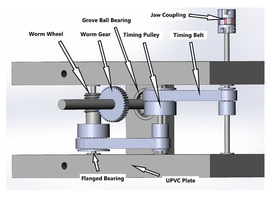
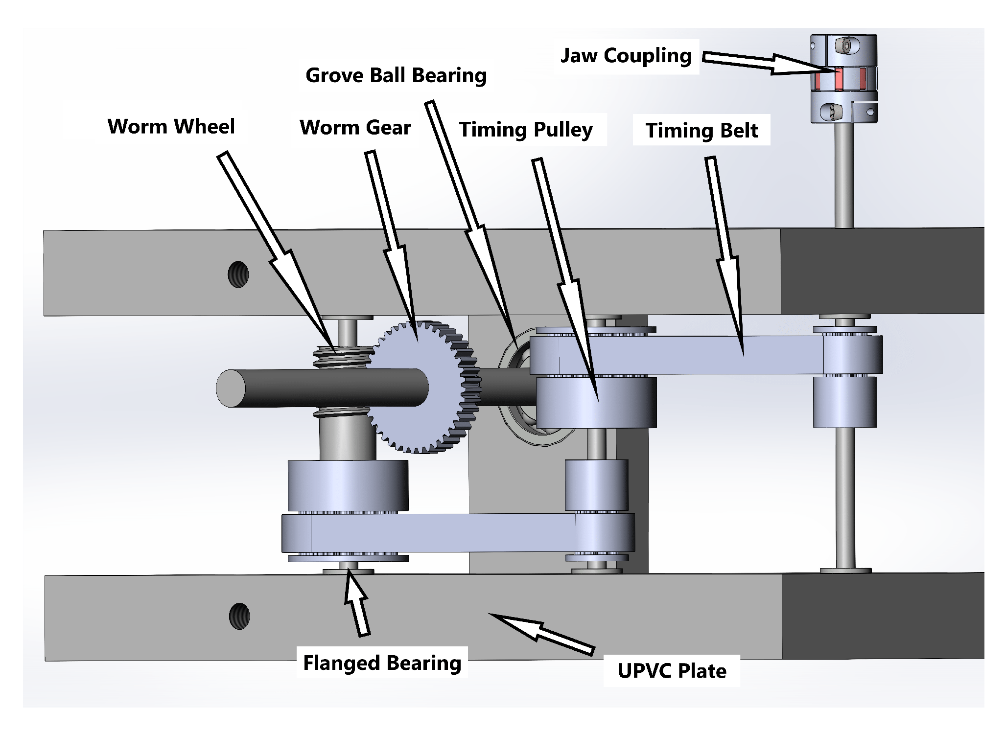
As show in Figure 3, the transmission system’s first component is a jaw coupling responsible for transmitting the torque from the turbine’s shaft onto a two-stage speed reduction system, consisting of four aluminium timing pulleys of a pitch of 2.032 mm connected with two timing belts. Such a small pitch benefits from a higher maximum belt speed, higher accuracy, and reduced backlash, as well as leading to smaller overall pulley sizes, which is essential in a system where size is a determining factor to be minimised. The final stage of the transmission system is a worm wheel and gear set, which further increases the torque and has a locking effect, allowing motion to be transmitted uniquely from the input to the output axis, achieving what is known as a non-back-drivable mechanism (NBDM) [13,14].
Figure 3.
CAD assembly of the transmission system, showing a jaw coupling, 4 timing pulleys, 2 timing belts, a worm wheel, and a worm gear. Threaded bars 3 mm, 4 mm, and 6 mm in diameter were used to fix the components to the plates. One of the plates for the worm gear is hidden from the assembly for visibility, as well as the supports which hold the two main plates at a fixed distance.
The initial prototype for the transmission design aimed to test its functionality, prioritising simplicity over factors such as weight, size, or aesthetics. Parameters were selected to accommodate previously ordered components, rather than modifying parts to fit the design. Clearance distances of 0.1-0.2 mm were chosen to minimise friction and tension, with components cleaned and lubricated to reduce operational friction. Assembly involved fitting components onto two UPVC base plates, tightening pulleys with grub screws, and securing bearings with an interference fit, occasionally gluing for permanence.
The gear ratio of the two stages of pulleys can be found using their pitch diameters, or equally, the number of teeth on each pulley. The driving pulley in each stage contains 10 teeth and the driven pulley 24 teeth, so the total gear reduction ratio GR is as follows:
Gear reduction also leads to an increase in torque by the same factor, which is essential to produce an actuation force that can overcome the resistance and friction in the system and provide a sufficient grip force, which, with high-friction finger covers, would be able to hold a range of objects. Nevertheless, a is still insufficient for achieving a high enough torque, so further speed reduction is necessary. This is achieved by a worm drive set, which serves two primary functions: increasing torque by reducing speed and providing a non-back-drivable mechanism (NBDM) for safety and functionality. The worm drive accomplishes both tasks by meshing the worm wheel and gear, allowing for gear reduction and shear-friction-based locking. According to worm wheel theory, the critical lead angle under which effective locking would be achieved for a static coefficient of friction when lubricated with [15] was , and so a set with was chosen. Additionally, introducing this component multiplied to gear ratio by 40, to a total of .
2.3. Differential Subsystem Design
The previous Airbender featured single-finger actuation (index) against a fixed thumb [7]. While proving useful for many applications such as performing a pinch grip, it inevitably limits the types of objects that can be securely picked up and the range of tasks that can be performed. Upgrading the system such that all fingers are actuated by the breathing input would increase the dexterity, functionality, and naturality of the device.
A multi-finger actuated prosthesis does not feature multiple actuators, but a single one that is able to actuate all fingers. Inevitably, the number of actuators will be lower than the number of degrees of freedom (DoFs) in the prosthesis, leading to an underactuated system. To achieve complex grasps and manipulation tasks, DoFs must be replaced with passive actuators which cannot be controlled [16]. The use of these leads to an adaptive grap so that when one finger or phalanx comes into contact with a surface and “stops”, the other fingers and phalanges continue to close and wrap around the object. This mechanism is feasible only with the use of a differential mechanism in combination with mechanical stops or elastic elements (passive actuators).
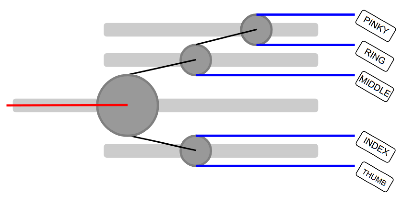
Many articles explore the use of gear-based differential mechanisms [17] or continuum differential mechanisms [18], but this work focuses on an alternative mechanism based on pulleys. The idea entails introducing the pulley into rails to restrict their motion into a single dimension and allowing the pulley to rotate around its axis. Cascading pulleys and strategically connecting them can generate a differential output in a translational manner, where pulleys will slide along the rails until an equilibrium position is reached.
Based on the load distribution experienced by five different sections of the hand when holding a 200 mm diameter cylinder, explored by Mühldorfer-Fodor et al. [19], the chosen pulley configuration was able to distribute the force provided by the driving tendon, as shown in Table 2.
Table 2.
Chosen force distribution as a percentage of the force provided by the actuating tendon.
This force distribution achieved by assembling the pulleys is shown in Figure 4. In this setup, pulling from the driving tendon (red) will pull from each of the pulley stages and allow them to slide and rotate until the system regains equilibrium again. To ensure the system is as efficient as possible, the angles that the connecting tendons (shown in black) make with the horizontal axis are to be minimised, as well as friction between the pulleys and the railings.
Figure 4.
Differential system diagram, viewed from the palmar orientation of a right hand. Pulleys = dark grey, connecting tendons = black, driving tendon = red, actuating tendons = blue, and railings = light grey.
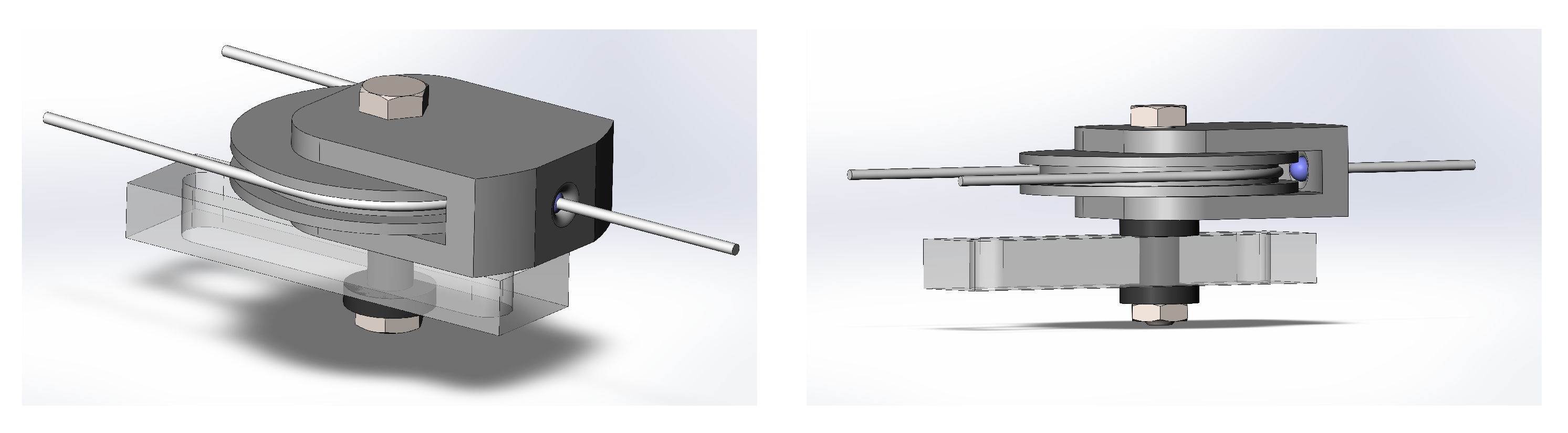
To implement the idea, a pulley and support were designed for free pulley rotation and tendon attachment. A CAD model in SolidWorks 2021, shown in Figure 5, depicts the design. A 0.2 mm clearance on each side of the pulley reduces friction, while 1 mm flanges prevent tendon slippage. The system’s efficiency is increased by using low-friction nylon supports to connect the pulleys to the base plate and employs smaller diameter pulleys in the second and third stages to reduce tendon angles.
Figure 5.
CAD assembly of the pulley, its support, and the low friction black nylon dumbbell-like shape, mounted to the railing. All the components are being held together by a bolt and nut.
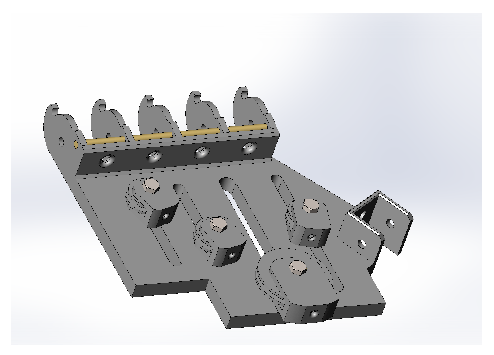
The hand plate features a joint mimicking the proximal interphalangeal joint (PIP) for simplicity, aligning fingers for flexion and extension, but not abduction or adduction, minimising the weight and design complexity [20]. The assembly CAD model can be observed in Figure 6.
Figure 6.
CAD assembly of the base plate and the differential system. The tendons are not included in the design for visualisation purposes, and the differential system would in practice be covered by a top plate.
2.4. Actuation Subsystem Design
The previous design of the Airbender was limited in its functionality, as it featured fixed fingers in which only the index finger was able to rotate about the metacarpophalangeal joint, i.e., the joint between the metacarpals and proximal phalanges. Keeping the remaining fingers in a fixed position limited the variety of tasks the user could perform, since most tasks require multiple fingers to work in unison. The advantages of a multi-finger actuation system by means of the previously suggested differential system are amplified when combined with multi-joint fingers which can adapt to grasp objects of variable sizes, providing an enhanced grip with increased dexterity and improving the naturalness of the device as a whole.
For this reason, this paper introduces multi-joint fingers that require actuation for both flexion and extension. This could be achieved through the use of a double actuation mechanism that employs the bidirectionality of the Tesla turbine to either flex or extend the joints. Alternatively, a single actuation tendon coupled with a restoring mechanism would reduce the system complexity and minimise the potential points of failure [21].
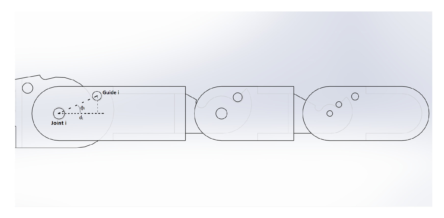
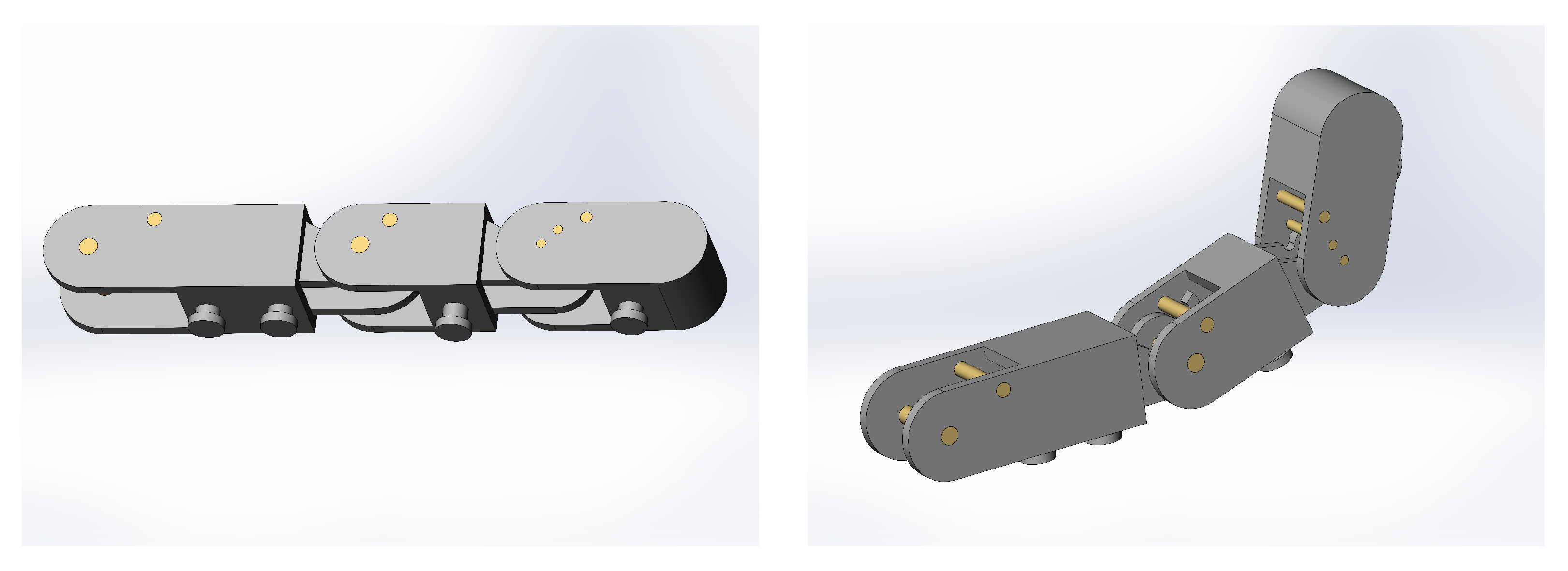
The finger’s design includes three phalanges, each of which contains a tendon guide at an axial distance and angle to the pivot axis of the joint. Additionally, a fourth guide is placed on the base plate to maintain the tendon under tension even when the finger is extended. Finger dimensions are standardized for simplicity: proximal phalanx (45 mm), middle phalanx (25 mm), and distal phalanx (25 mm, excluding a curved tip for stability), with a width of 16 mm. The finger assembly can be observed in Figure 7.
Figure 7.
Schematic of finger assembly showing 3 phalanges, 4 guide points, and one tendon attachment support located at the end of the distal phalanx. The tendon would run between the guide points and joints and be attached to the final attachment support.
To determine the position of the guide points, an objective function suggested by Gosselin et al. [21] in terms of and is maximised by resolving it numerically, converging to the optimal finger parameters shown in Table 3.
Table 3.
Optimal finger parameters for the guide positions of the proximal (1), middle (2), and distal (3) phalanges.
The strategic positioning of these guides allows for fingers to follow a proper flexing sequence, beginning with the MCP (metacarpophalangeal joint), followed by the PIP (proximal interphalangeal joint) and finally the DIP (distal interphalangeal joint). This sequence is crucial for effective grasping as flexion of a more distal joint prior to a proximal joint could result in the object slipping away. Nevertheless, the use of a single tendon made of string only provides the forces necessary for finger flexion, but not extension. This drives the need for a restoring force that “actuates” the finger in the opposite direction, which can be achieved through the use of elastic bands.
These elastic bands would be positioned at the back of the finger and would generate a restoring force as the finger flexes. It is crucial to choose an elastic band with stiffness k that provides a momentum around the joint large enough to overcome the momentum created by the weights of the assembled phalanges. Nevertheless, a trade-off exists, since a stiffness that is too high would effectively reduce the grip strength at maximum finger flexion, since the restoring force of the elastic band is proportional to its extension.
A tensile test was performed on the commercially elastic bands to plot the force vs. extension relationship, and conclude whether the restoring force provided at different extensions was sufficient to extend the joints. Once the experiment confirmed this hypothesis, the elastic bands were incorporated through the design of simple supports at the back of each of the phalanges and the base plate, as shown in Figure 8.
Figure 8.
CAD assembly of a finger, printed in ABS plastic and using metallic shafts for both joints and guides. A clearance of 0.2 mm was used to reduce friction upon assembly. Two elastic bands are attached across the joints, using the small extrusions beneath the fingers. An additional elastic band is attached from beneath the hand plate to the proximal phalanx extrusion.
2.5. Full Design
To construct the prototype, each of the three phalanges was 3D-printed separately using ABS plastic and assembled using carefully selected brass or steel rods. ABS plastic was selected for its post-processing versatility, as it can be sanded and glued easily, both of which were necessary steps in the production process.
For subsequent testing using a controlled and steady air input, it was necessary to mount the design into a test bench. To do so, different components had to be designed in SolidWorks 2021 to ensure a secure setup when connected to the turbine and test bench. To connect the transmission system output to the input of the differential system, the driving tendon was attached to the shaft to which the worm gear was connected through a 1 mm drilled hole.
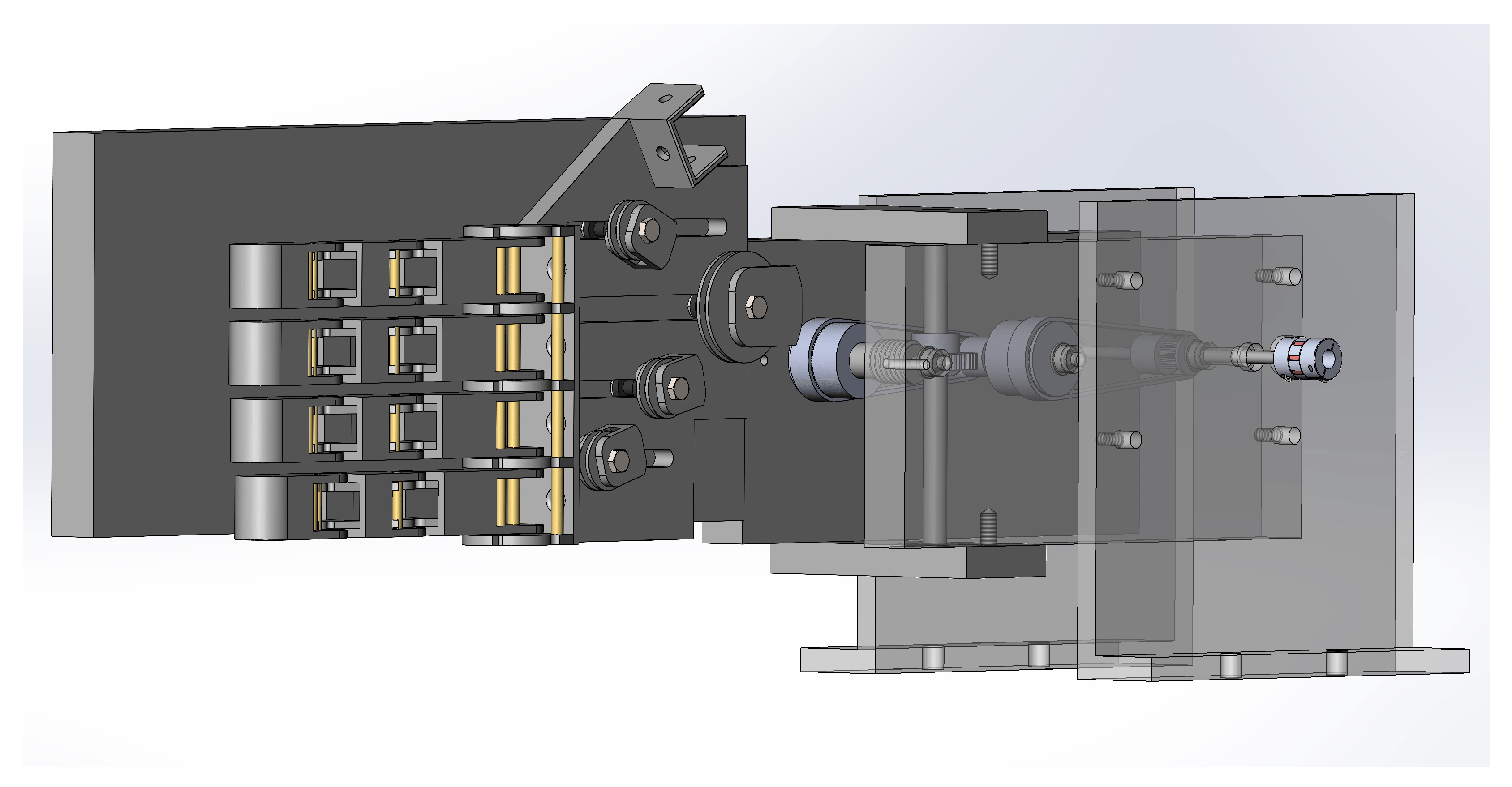
A CAD of the assembled setup can be seen in Figure 9. The aim of this first stage prototype is to test the engineering principles of the turbine, transmission, and actuation systems, prioritising simplicity over a design that has the practical dimensions, weight, and materials that make it suitable for in-field use.
Figure 9.
CAD assembly of all components in the system, with the exception of the turbine. This includes the transmission, differential, and actuation systems, as well as the plates required to assemble these to the test bench.
2.6. Test Bench
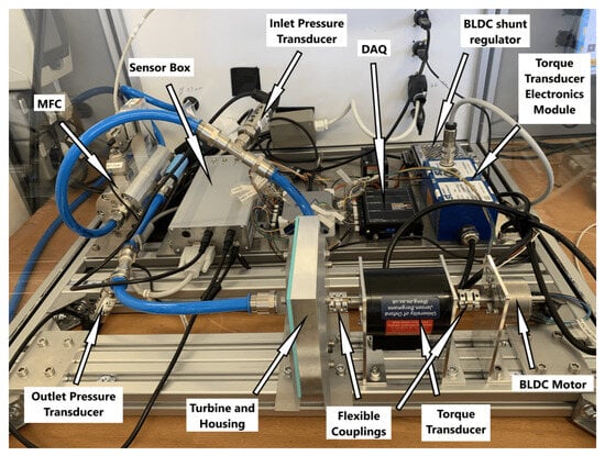
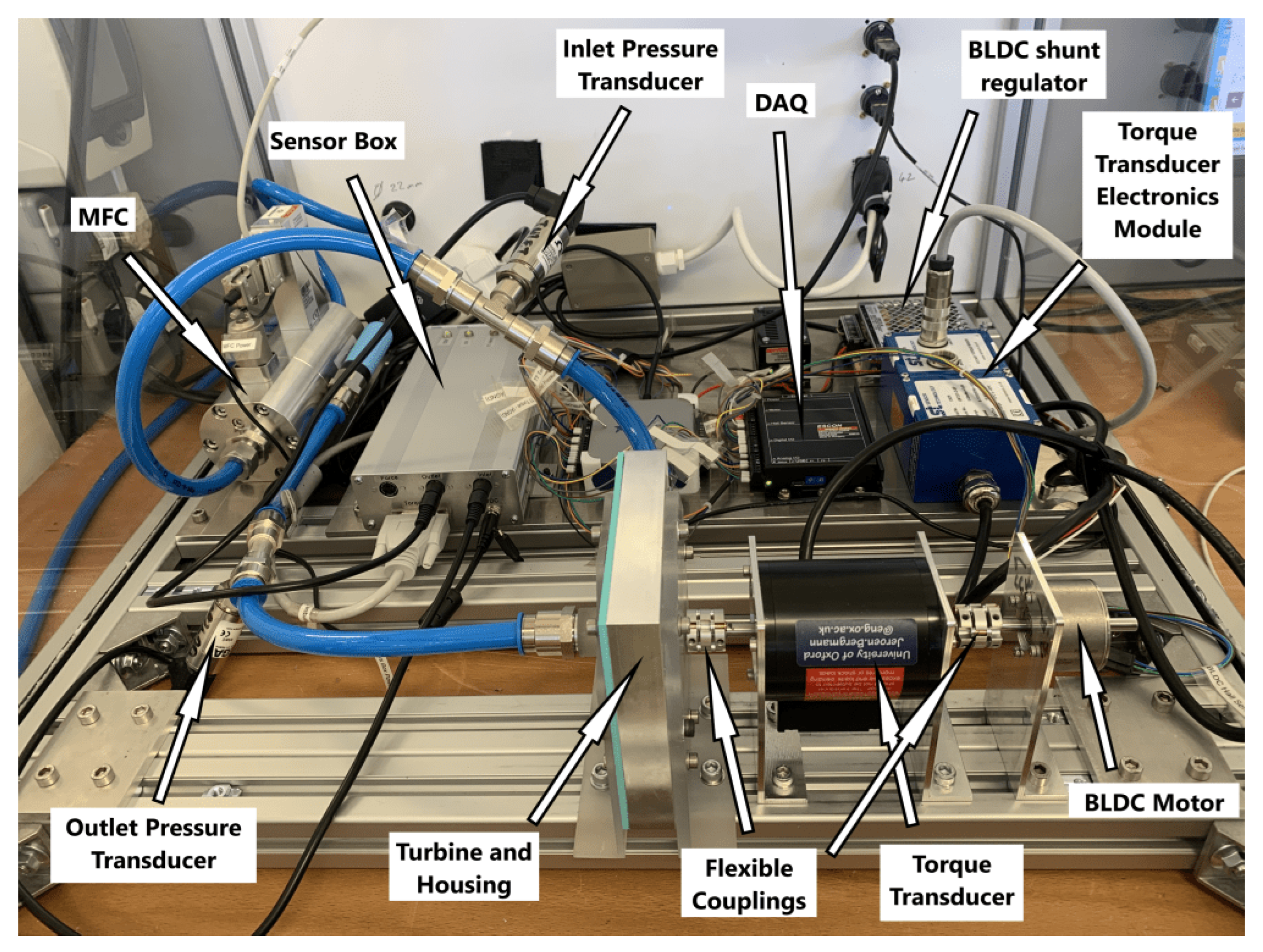
To experiment with a range of flow rates in a controlled and safe environment, Lopes designed a test bench to obtain measurement data from Tesla turbines. The test bench, shown in Figure 10, is connected to a clean and dry air supply at 6.5 bar, which flows into the mass flow controller (MFC). From the MFC, the air is directed along a tube through the inlet pressure transducer before directly leading to the turbine casing inlet. After flowing through the turbine, the air exits through the exhaust along another tube, passes across the outlet pressure transducer, and exits the system through a standard silencer. The entire system is enclosed in a box made of PETG impact-resistant panels for safety.
Figure 10.
Overall view of the test bench, mounted with a turbine.
Within the test bench, the turbine shaft is coupled to the brushless direct current (BLDC) motor, which itself is connected to the torque transducer using flexible couplings (to correct for <1 mm misalignments). The motor speed can be adjusted using the servo motor controlling unit, which forces the turbine to rotate at that same speed. By controlling the speed to the system, a load can be introduced to the turbine when it is generating power. The BLDC then acts as a generator, absorbing the energy generated by the turbine. The controller is dynamically breaking the motor, which means that the turbine is running at a higher speed than the one it is being restricted to run at, generating a positive torque measurement. It is important to ensure the motor is running in the same direction the air input is forcing the turbine to run, to obtain meaningful data. There are also cases where the flow on the turbine is not sufficient to generate energy. In this scenario, the BLDC motor will supply energy to the turbine to maintain the desired speed, essentially working as a compressor. The power measured will be negative.
The test bench was used to test the turbine by itself, the transmission system, and the functionality of the entire assembly.
3. Results
To ensure the functionality of the assembled system, it is equally important to test the operation of each of the subsystems. Therefore, the results section in this paper is subdivided into several subsections, described below in further detail.
3.1. Turbine Performance
Measuring the torque output for different air flow rates at a range of operating speeds for the Tesla turbine by itself provides a basis for results when other subsystems such as the transmission or differential systems are connected. Connecting other subsystems introduces a load and losses, so one would expect that higher rotational speeds at any given flow rate would be reached.
Prior to obtaining any torque vs flow rate visualisations, it is important to understand the nature of the data obtained. This includes assessing whether a normal distribution is suitable to accurately represent the torque data obtained by means of a statistical analysis. To investigate this hypothesis, torque measurements were obtained for typical expiration flow rates for children and adolescents under the age of 18 [8], for a range of operational speeds.
Once the data have been obtained, a series of statistical tests were performed to analyse the data’s normality and independence. Firstly, a Shapiro–Wilk test, considered by Razali et al. as the most effective formal statistical test of normality [22] and also supported by the conclusions from other authors [23,24,25], consisted of using the range of the data set w and its standard deviation to calculate a test statistic q, where . For a given significance level , a comparison of this test statistic q with a critical range over which to accept the null hypothesis that the data can be statistically represented by a normal distribution can be made. In this case, a significance level was chosen for a sample size of , making the critical range [26]. The resulting q values are shown in Table 4.
Table 4.
Table showing q values for the obtained torque measurements, ranging from speeds of 1000 to 5000 RPM as well as flow rates of 100 to 400 Ls/min. The values lying outside the critical range are highlighted in orange (less than away from the critical value) and red (more than away from the critical value).
From the table, there is a general trend that low flow rates combined with low operational speeds result in q values lying outside the critical range. This could be explained by the fact that torque measurements at these operational conditions are of lower magnitude, causing measurement variations due to error and transient fluid fluctuations to be more considerable, deviating results from normality. Nevertheless, >85% of the q values were less than off the lower boundary critical value of 4.31 (shown in orange). While it is acknowledged that not all data are best represented by a normal distribution, this metric demonstrates a high enough suitability in representing the measurements, thus accepting the null hypothesis .
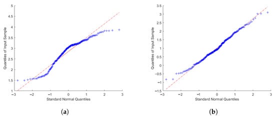
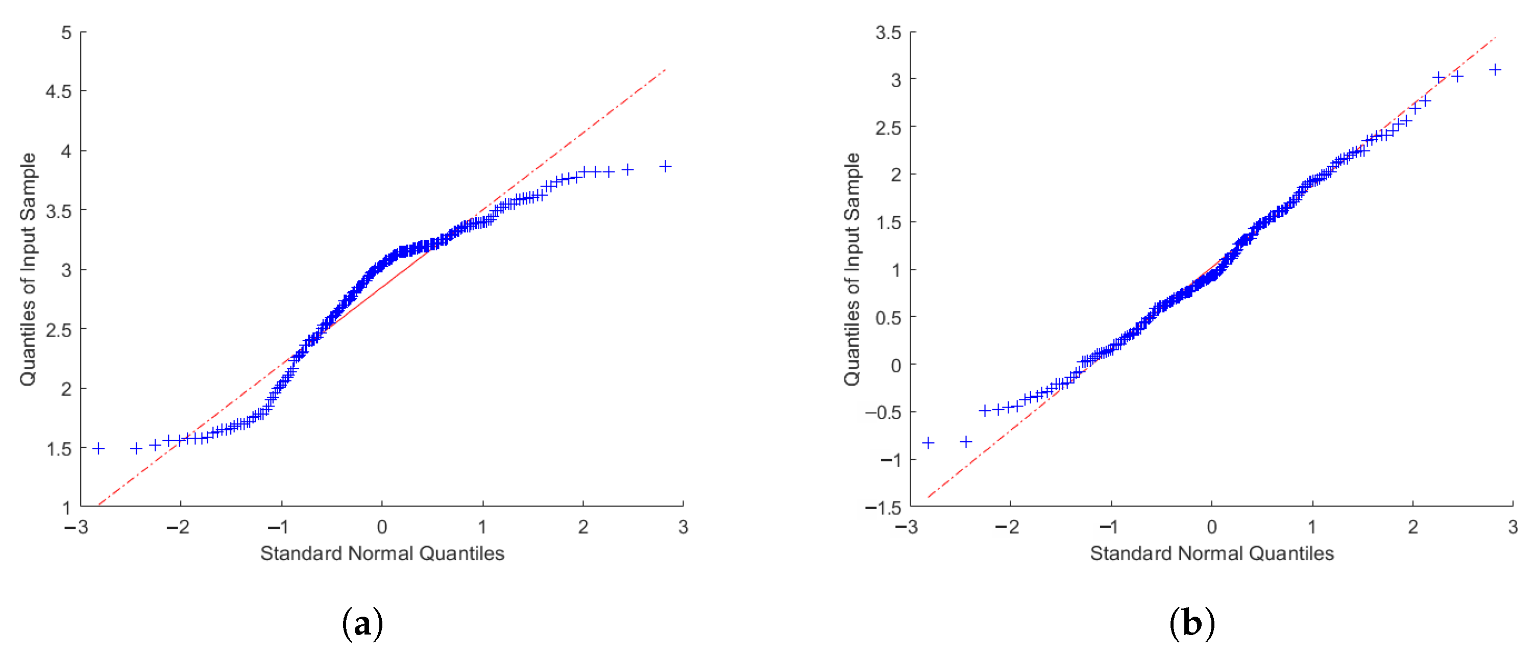
To visualise this deviation from normality, graphical methods such as quantile–quantile (QQ) plots can be used. Plotting such graphs provide an indication of univariate normality in the dataset, by examining how far points deviate from a 45-degree reference line [27]. To display the difference between data that could be treated as originating from a normal distribution and data that could not, the best and worst case results from Table 4 are shown in Figure 11. The clear deviation from normality (45-degree line) further supports the claim that some of the data are not best represented by a normal distribution.
Figure 11.
QQ plots for data using a significance level , showing the reference for a perfect normal distribution in red. (a) 2500 RPM with FR = 300 Ls/min, the test with the worst q value. (b) 5000 RPM with FR = 350 Ls/min, the test with the best q value.
The previous statistical tests were used to analyse the torque data within each data logging, but it is also important to perform formal tests across different data loggings to determine whether changing the operating conditions of the test bench (speed and flow rate) statistically affect results. A common statistical test to conduct is the ANOVA (Analysis of Variance). Its objective is to provide confidence that, under the same test-bench operating conditions, the data obtained in different data logging instances will provide similar means, represented as the null hypothesis .
Additional information on the ANOVA and post hoc analyses can be found in the Supplement Materials for this publication, but in conclusion, results indicate that fully optimising the design should make ANOVA and post hoc results form clearer trends.
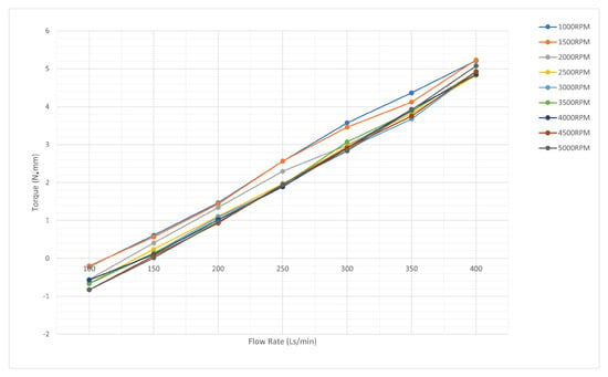
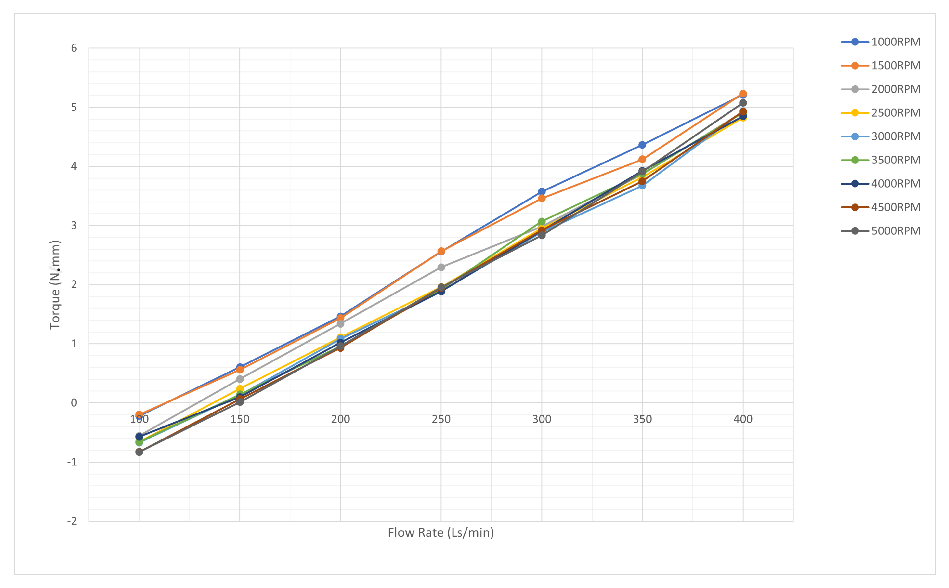
After confirming that data could be statistically represented by a Gaussian distribution, a set of torque data loggings for a range of air flow speeds were tested, fixing the BLDC motor speed. The results can be observed in Figure 12.
Figure 12.
Graph of torque vs. flow for different operating speeds.
The graph illustrates that higher rotational speeds lead to lower torques at a given FR, due to the decreasing relative velocity of the turbine discs and the air flow. It can be observed that, especially at the lower range of flow rates, the torques recorded by the torque transducer are in fact negative, implying that under certain conditions energy is being drawn from the BLDC into the turbine, making it virtually act like a compressor.
Additionally, the intersection occurs at a higher FR as the turbine speed increases. From the data, using linear interpolation, the FR required to maintain the turbine rotating at a given speed can be extracted, with the results shown in Table 5. Note that these FRs provide an upper limit on the achievable RPMs, as the assembly of the remaining subsystems in the prosthesis would act as a load and introduce additional friction.
Table 5.
Table showing the FR requirements for running the turbine at different operational speeds freely.
3.2. Differential and Actuation
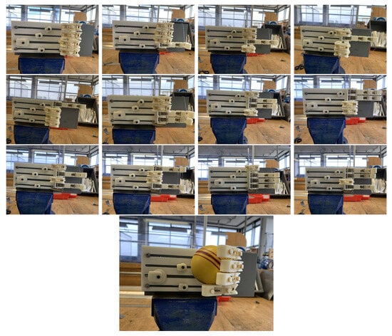
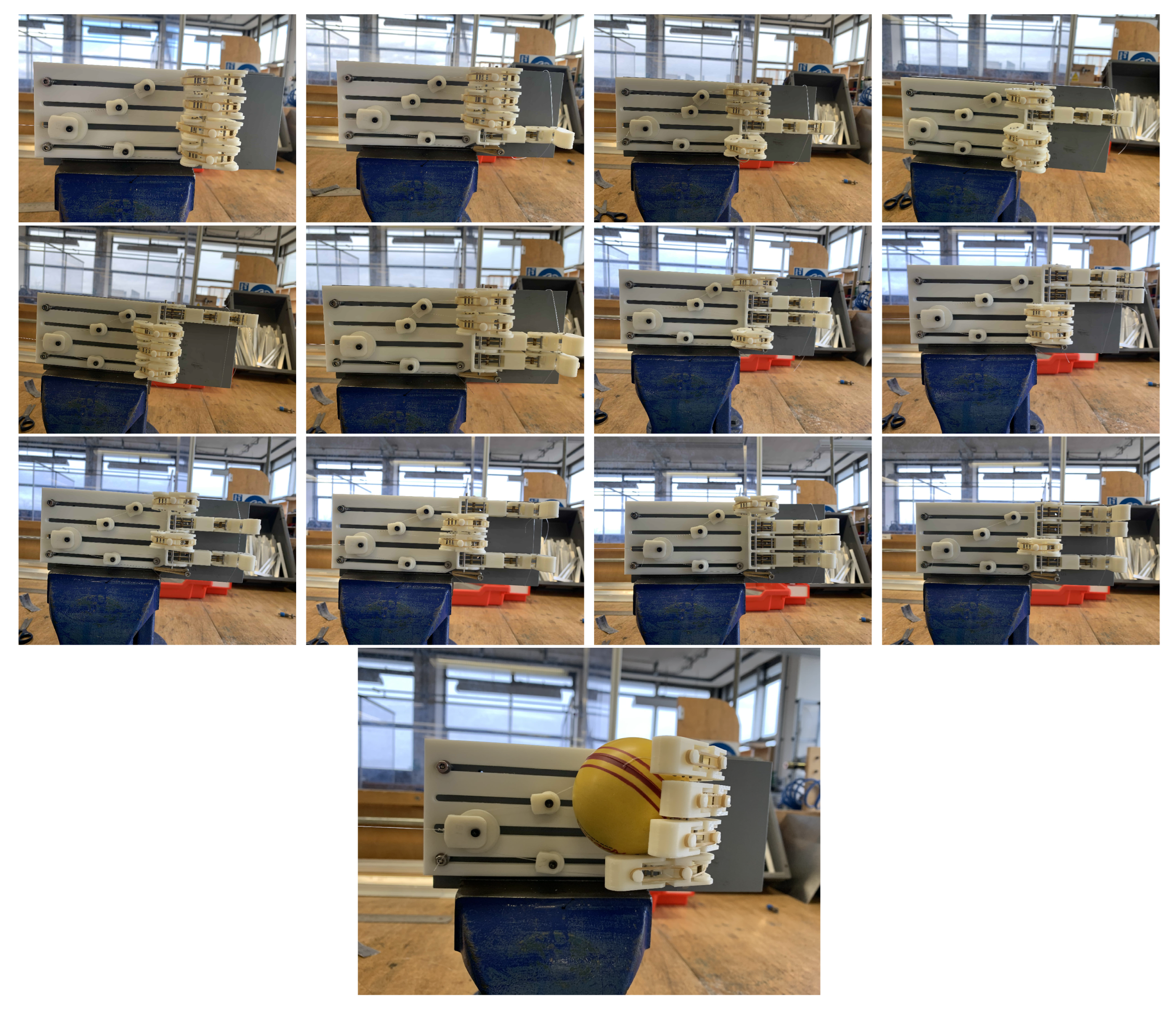
To demonstrate the functionality of the differential subsystem, a longer base plate was 3D-printed to allow pulleys to slide continuously and prevent them from coming into contact with one another. The fingers were assembled and connected to the differential using a 19.3 kg 0.5 mm monofilament nylon line, and different finger actuation combinations were tested by manually pulling from the driving tendon (view Figure 4). The images in Figure 13 show the successful application of a multi-finger actuation device, which can actuate any combination of fingers with a single actuation input. Additionally, these results indicate that more intricate flexion configurations, including the partial flexion of specific fingers, are also feasible, demonstrated with the last image, which shows the prosthesis’ ability to wrap around curved edges.
Figure 13.
These images show examples of hand gesture combinations executed by selectively locking each of the four fingers, or a combination of these. The final image shows the four fingers holding a sphere when the final position is reached and the air flow has halted. They serve as visual confirmations of the differential and actuation systems’ combined functionality.
3.3. Full Assembly
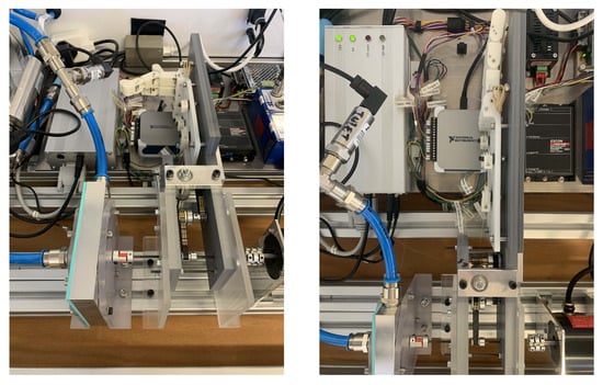
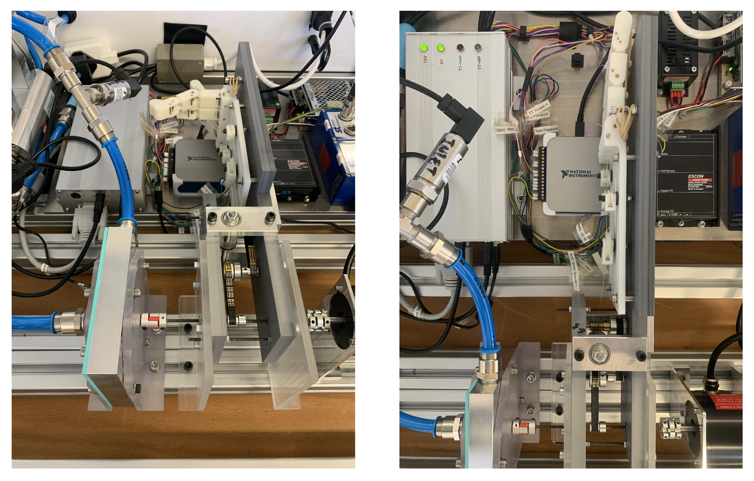
The purpose of this test is to explore the extent and actuation speed that could be achieved with different flow rates using the test bench, as observed in Figure 14.
Figure 14.
Entire assembly mounted onto the test bench.
To conduct the experiment, the flow rate was initially set to 400 Ls/min, and the time elapsed after the rotation of the turbine began was recorded until the system reached a static state again. It is worth noting that there was a delay between the start of the air flow and the beginning of system rotation, as reaching the pre-set value was not instantaneous. The system would eventually reach equilibrium, either because the actuation was completed or the force generated was insufficient to overcome the system load and friction. At this point, the air input was stopped and the degree of actuation, expressed as a percentage of full actuation, was approximately recorded (to an accuracy of ). The experiment was then repeated for decreasing flow rates, in steps of 10 Ls/min until there was no actuation. The entire procedure was then repeated to provide confidence in the accuracy and reliability of the results.
The actuation times and extents are presented in Table 6. The results indicate that for flow rates where full actuation was reached, the actuation time was approximately constant, suggesting that there is a limit at which the transmission system operates regardless of the flow rate. This actuation time only began to increase in tests in which the flow rate was insufficient to achieve full actuation. It is important to consider that actuation times are also a function of the actuation extent, so these data are not directly comparable with those of full actuation cases.
Table 6.
Table showing the actuation times and the approximate actuation extents for the two tests conducted. These actuation extents were manually noted and are considered approximations (to an accuracy of ). According to the clinical study conducted by V. H. Nagaraja et al. [8], adolescents aged 14 years or older had a peak expiratory flow rate above 340 Ls/min.
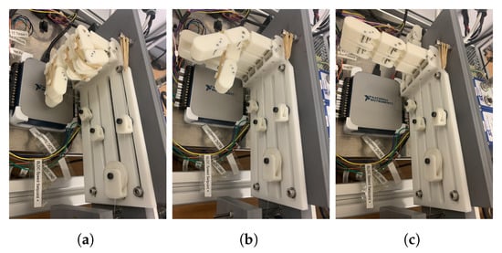
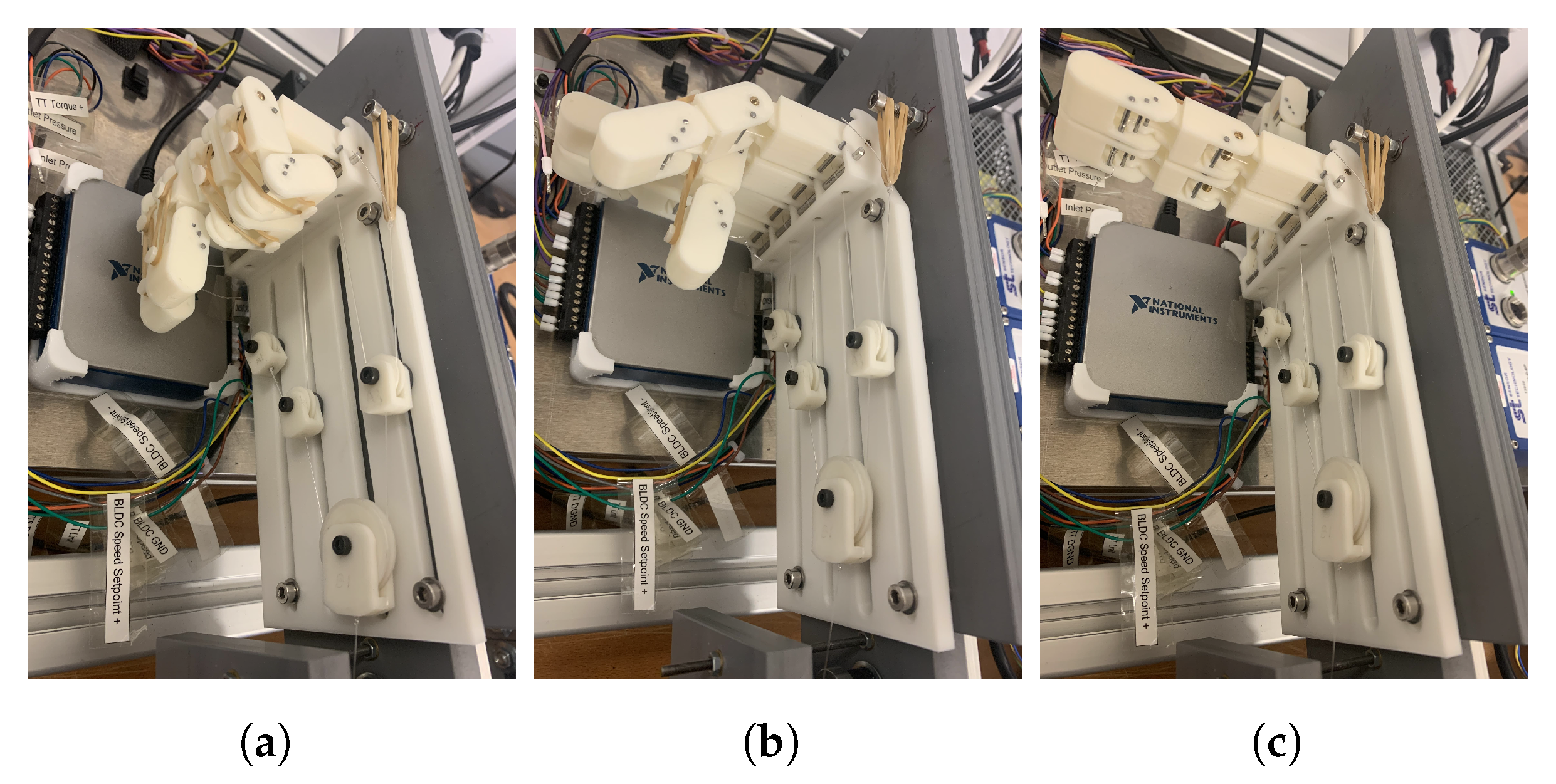
Figure 15 shows some examples of what varying actuation extents looked like, to illustrate what is meant by a different actuation % in Table 6.
Figure 15.
Actuation extents. (a) 95%. (b) 50%. (c) 20%.
4. Discussion
This prototype is the first proof-of-concept of a breathing-powered, multi-finger actuated UL prosthesis. While far from a deployable device, the results demonstrate a feasible concept that could be further optimised to improve both closing time and grip strength, while still aiming to reduce size, weight, and inefficiencies. The turbine could be also integrated into the palm to provide a more anthropomorphic design, as previously suggested [7]. Young patients with a limb difference have mentioned it was comfortable to operate the Tesla turbine on a short-term basis [8]. The system must undergo evaluation in a real-world context using a prototype that demonstrates an adequate ergonomic design and is appropriate for patient use.
The main metric assessed in this study is actuation time. Results show that, for flow rates allowing full actuation, the time remained approximately constant, suggesting a threshold beyond which the transmission system’s performance does not significantly vary. Actuation time increased only when the flow rate was insufficient. These times remain well above the range considered acceptable for daily tasks (0.8–1.5 s) according to Tözeren or Dechev et al. [28], but modifications to the transmission and differential systems could greatly reduce them. As shown, the cascading pulley system can allow for continuous force transmission without backlash to achieve an adaptive grip. Although there are benefits in terms of weight and cost for using this approach, several issues remain. Future work could focus on improving transmission efficiency and torque through different pulley arrangements, gear ratios, and materials. Reducing backlash by using a single-stage pulley system, higher-quality components, or optimised gearing may also improve performance. Refinements to the differential system—such as smoother surface finishes or the use of ball bearings—could further reduce friction and improve responsiveness. Additionally, investigating wear over time could highlight which components degrade with use and how this impacts function.
The force estimated for the higher torque generated (5 Nmm) is ∼6 N without the worm drive set, and this increases considerably when a worm drive is applied. Nonetheless, there will be a loss of efficiency at the different stages (e.g. worm gear, cable system friction). The overall efficiency is likely to be around 0.5, indicating that we might reach a grip force of 60 N for the entire system. This force would translate into 15 N for the thumb, index, and middle finger, whilst the ring and pinky will generate 7.5 N each. Most basic activities of daily living should be possible with such a grip force.
It should be noted that there will be efficiency drops at low flow rates, as the Tesla turbines rely on boundary layer adhesion. At lower flow rates, the drag effect is reduced. This was also observed in this study, with lower flow rates yielding no or low activation of the turbine. There is also a risk of the turbine stalling at lower flow rates. This indicates that the user should aim to reach the higher flow rates that were obtained in this study. The reported mean flow rate for children, who fit the potential user population, was 312.7 ± 97.2 Ls/min (range 150–500) [8]. Reducing the required flow rate for actuation would thus be useful to ensure everyone would be able to operate such a prosthetic.
Another key area is the thumb, which should ideally include an additional DOF to provide counterforce to the fingers. Studies in the literature [17,29,30] propose a manually adjustable DOF, allowing users to preset the thumb’s position based on the task. Finger sizing could also be adapted to better mimic natural proportions, considering both length and width. The restoring mechanism may benefit from customised elastic band stiffnesses tailored to each joint and user profile, rather than using uniform bands. Moreover, redesigning the joint mechanisms and phalanx geometry—especially at the MCP—could enhance the naturalness of motion, reduce friction, and enable abduction/adduction, expanding the functional range of the prosthesis. Moreover, improvements to the differential system, such as refining manufacturing techniques to improve surface finish and incorporating ball bearings for smoother movement, could contribute to reducing actuation time and achieving more efficient prosthetic operation. Another area of focus would be studying the long-term effects of repeated use of the prosthesis to identify locations where wear can impact performance.
Next steps should include effect size analysis to evaluate whether observed differences have practical significance. Sensitivity analyses, such as varying sample size or statistical models, would help assess the robustness of the findings.
Finally, future work should involve conducting clinical studies with UL-deficient individuals to gather feedback on each of the design iterations’ functionality, usability, and effectiveness. Involving the same patients that took part in the first clinical study on the Airbender [8] would allow for a comparison between the two systems, assisting prototype developments in incorporating the effective aspects of the previous Airbender into future design concepts as well as the most popular characteristics of this one, improving the prosthesis’ durability, aesthetics, comfort, and affordability, and hence overall satisfaction.
5. Conclusions
This study has shown that both theoretically and practically, a breathing-powered multi-finger UL prosthesis is feasible, allowing for complex grasping configurations whilst benefiting from the affordability and simplicity of such devices. After testing the device with the test bench, the minimum flow rate required for full actuation was found to be 340 Ls/min; according to the PEFR clinical study [8], most children aged 13 or older would be capable of operating the device. Although full actuation was achieved, the observed times (≈12 s) were found to exceed those of other commercially available prostheses. This work serve as a starting point for future optimisation.
Supplementary Materials
The following supporting information can be downloaded at: https://www.mdpi.com/article/10.3390/prosthesis8010007/s1, Document S1: Details on the statistical analysis that was performed. References [31,32,33,34] are cited in the Supplementary Materials.
Author Contributions
Conceptualization, J.H.M.B.; methodology, J.H.M.B., J.d.P.L. and I.D.L.J.; Verification, I.D.L.J.; formal analysis, I.D.L.J.; test bench development, J.d.P.L.; resources, J.H.M.B.; writing—original draft preparation, I.D.L.J. and J.H.M.B.; writing—review and editing, J.H.M.B. and J.d.P.L.; visualization, I.D.L.J.; supervision, J.H.M.B.; project administration, J.H.M.B.; funding acquisition, J.H.M.B. All authors have read and agreed to the published version of the manuscript.
Funding
This research was funded by the EPSRC Impact Acceleration Account (Award EP/R511742/1) and by the National Institute for Health and care Research (NIHR) HealthTech Research Centre for Community Healthcare at Oxford Health NHS Foundation Trust. The views expressed are those of the author(s) and not necessarily those of the NHS, the NIHR, or the Department of Health and Social Care.
Data Availability Statement
The raw data supporting the conclusions of this article will be made available by the authors on request.
Acknowledgments
The authors would like to thank Peter Walters for support with the additive manufacturing, and Cleveland Williams and Philip Lacey for support with the experimental setup.
Conflicts of Interest
The authors declare no conflicts of interest.
References
- Cordella, F.; Ciancio, A.L.; Sacchetti, R.; Davalli, A.; Cutti, A.G.; Guglielmelli, E.; Zollo, L. Literature review on needs of upper limb prosthesis users. Front. Neurosci. 2016, 10, 209. [Google Scholar] [CrossRef] [Scilit] [PubMed]
- Ephraim, P.L.; Dillingham, T.R.; Sector, M.; Pezzin, L.E.; MacKenzie, E.J. Epidemiology of limb loss and congenital limb deficiency: A review of the literature. Arch. Phys. Med. Rehabil. 2003, 84, 747–761. [Google Scholar] [CrossRef] [Scilit] [PubMed]
- Nikolajsen, L.; Christensen, K.F. Phantom limb pain. Nerves Nerve Inj. 2015, 4, 23–34. [Google Scholar]
- McLaughlin, M.; Lisenby, S.; Sharma, S.; Modrcin, A.C. Congenital Upper Limb Deficiency. Available online: https://now.aapmr.org/congenital-upper-limb-deficiency/ (accessed on 9 August 2025).
- Body-Powered Arm Prosthesis. Orthoworks—Orthotics. Available online: http://www.orthoworx.co.za (accessed on 12 March 2025).
- Castellini, C. Upper Limb Active Prosthetic Systems—Overview. In Wearable Robot; Academic Press: Cambridge, MA, USA, 2020; Volume 4, pp. 365–376. [Google Scholar]
- Nagaraja, V.H.; da Ponte Lopes, J.; Bergmann, J.H.M. Reimagining prosthetic control: A novel body-powered prosthetic system for simultaneous control and actuation. Prosthesis 2022, 4, 394–413. [Google Scholar] [CrossRef] [Scilit]
- Nagaraja, V.H.; Moulic, S.G.; D’souza, J.V.; Limesh, M.; Walters, P.; Bergmann, J.H.M. A Novel Respiratory Control and Actuation System for Upper-Limb Prosthesis Users: Clinical Evaluation Study. IEEE Access 2022, 10, 128764–128778. [Google Scholar] [CrossRef] [Scilit]
- Belter, J.T.; Segil, J.L.; Sm, B.S. Mechanical design and performance specifications of anthropomorphic prosthetic hands: A review. Supt. Doc. 2013, 5, 599. [Google Scholar] [CrossRef] [Scilit] [PubMed]
- Romanin, V.D. Theory and Performance of Tesla Turbines. Doctoral Dissertation, University of California, Berkeley, CA, USA, 2012. [Google Scholar]
- Guha, A.; Smiley, B. Experiment and analysis for an improved design of the inlet and nozzle in Tesla disc turbines. Proc. Inst. Mech. Eng. 2010, 224, 261–267. [Google Scholar] [CrossRef] [Scilit]
- Sengupta, S.; Guha, A. A theory of Tesla disc turbines. Proc. Inst. Mech. Eng. Part J. Power Energy 2012, 226, 650–663. [Google Scholar] [CrossRef] [Scilit]
- Controzzi, M.; Cipriani, C.; Carrozza, M.C. Miniaturized non-back-drivable mechanism for robotic applications. Mech. Mach. Theory 2010, 45, 1395–1406. [Google Scholar] [CrossRef] [Scilit]
- Plooij, M.; Mathijssen, G.; Cherelle, P.; Lefeber, D.; Vanderborght, B. A theory of Tesla disc turbines. IEEE Robot. Autom. Mag. 2015, 22, 106–117. [Google Scholar] [CrossRef] [Scilit]
- The Engineering ToolBox. Friction—Coefficients for Common Materials and Surfaces. Available online: https://www.engineeringtoolbox.com/friction-coefficients-d_778.html (accessed on 9 August 2025).
- Massa, B.; Roccella, S.; Carrozza, M.C.; Dario, P. Design and development of an underactuated prosthetic hand. Proc. IEEE Int. Conf. Robot. Autom. 2002, 4, 3374–3379. [Google Scholar]
- Gao, G.; Shahmohammadi, M.; Gerez, L.; Kontoudis, G.; Liarokapis, M. On Differential Mechanisms for Underactuated, Lightweight, Adaptive Prosthetic Hands. Front. Media SA 2021, 15, 702031. [Google Scholar] [CrossRef] [Scilit] [PubMed]
- Xu, K.; Liu, H.; Liu, Z.; Du, Y.; Zhu, X. A single-actuator prosthetic hand using a continuum differential mechanism. In Proceedings of the 2015 IEEE International Conference on Robotics and Automation (ICRA), Seattle, WA, USA, 26–30 May 2015; pp. 6457–6462. [Google Scholar]
- Mühldorfer-Fodor, M.; Ziegler, S.; Harms, C.; Neumann, J.; Kundt, G.; Mittlmeier, T.; Prommersberger, K.J. Load distribution of the hand during cylinder grip analyzed by Manugraphy. J. Hand Ther. 2017, 30, 529–537. [Google Scholar] [CrossRef] [Scilit] [PubMed]
- Yan, Y.; Wang, Y.; Chen, X.; Shi, C.; Yu, J.; Cheng, C. A tendon-driven prosthetic hand using continuum structure. In Proceedings of the 2020 42nd Annual International Conference of the IEEE Engineering in Medicine, Biology Society (EMBC), Montreal, QC, Canada, 20–24 July 2020; pp. 4951–4954. [Google Scholar]
- Gosselin, C.; Pelletier, F.; Laliberte, T. An anthropomorphic underactuated robotic hand with 15 dofs and a single actuator. In Proceedings of the 2008 IEEE International Conference on Robotics and Automation, Pasadena, CA, USA, 19–23 May 2008; pp. 749–754. [Google Scholar]
- Razali, N.M.; Wah, Y.B. Power comparisons of shapiro-wilk, kolmogorov-smirnov, lilliefors and anderson-darling tests. J. Stat. Model. Anal. 2011, 2, 21–33. [Google Scholar]
- Mendes, M.; Pala, A. Type I error rate and power of three normality tests. Pak. J. Inf. Technol. 2003, 2, 135–139. [Google Scholar]
- Sıddık, K. Comparison of Several Univariate Normality Tests Regarding Type I Error Rate and Power of the Test in Simulation based Small Samples. J. Appl. Sci. Res. 2006, 2006, 296–300. [Google Scholar]
- Yap, B.W.; Sim, C.H. Comparisons of various types of normality tests. Taylor Fr. 2011, 81, 2141–2155. [Google Scholar] [CrossRef] [Scilit]
- Kanji, G.K. 100 Statistical Tests Sage; SAGE Publications: London, UK, 2006. [Google Scholar]
- Yuan, K.-H.; Liu, H.; Han, Y. Differential item functioning analysis without a priori information on anchor items: QQ plots and graphical test. Psychometrika 2021, 86, 345–377. [Google Scholar] [CrossRef] [Scilit] [PubMed]
- Dechev, N.; Cleghorn, W.L.; Naumann, S. Human Body Dynamics: Classical Mechanics and Human movement; Springer Science & Business Media: Berlin/Heidelberg, Germany, 1999. [Google Scholar]
- Schulz, S. First experiences with the vincent hand. In Proceedings of the 2011 MyoElectric Controls/Powered Prosthetics Symposium, Fredericton, NB, Canada, 14–19 August 2011. [Google Scholar]
- Gijsberts, A.; Bohra, R.; Sierra, G.D.; Werner, A.; Nowak, M.; Caputo, B.; Roa, M.A.; Castellini, C. Stable myoelectric control of a hand prosthesis using non-linear incremental learning. Frontiers 2014, 8, 8. [Google Scholar] [CrossRef] [Scilit] [PubMed]
- Steele, C. How (and When) to Use ANOVA in Excel: The Ultimate Guide. Go Skills. Available online: https://www.goskills.com/Lean-Six-Sigma/Resources/Use-anova-in-Excel (accessed on 9 August 2025).
- Tripathi, A.; Pandey, A. Post-hoc comparison in survival analysis: An easy approach. J. Biosci. Med. 2017, 5, 112. [Google Scholar] [CrossRef]
- Kucuk, U.; Eyuboglu, M.; Kucuk, H.O.; Degirmencioglu, G. Importance of using proper post hoc test with anova. Int. J. Cardiol. 2016, 209, 346. [Google Scholar] [CrossRef] [Scilit] [PubMed]
- Armstrong, R.A. When to use the b onferroni correction. Ophthalmic Physiol. Opt. 2014, 34, 502–508. [Google Scholar] [CrossRef] [Scilit] [PubMed]



Disclaimer/Publisher’s Note: The statements, opinions and data contained in all publications are solely those of the individual author(s) and contributor(s) and not of MDPI and/or the editor(s). MDPI and/or the editor(s) disclaim responsibility for any injury to people or property resulting from any ideas, methods, instructions or products referred to in the content. |
© 2026 by the authors. Licensee MDPI, Basel, Switzerland. This article is an open access article distributed under the terms and conditions of the Creative Commons Attribution (CC BY) license.