


Abstract
This paper presents an iterative graph-analytical procedure for determining the roll center height, one of the most critical design parameters influencing vehicle dynamic behavior during cornering. The conventional approaches generally determine roll center locations from suspension kinematics and then evaluate vehicle behavior using multibody or numerical vehicle dynamics models. By contrast, the proposed method is intended for the preliminary design stage and provides a direct correlation between front and rear target roll center heights using tire test data, load transfer and axle-level equilibrium conditions. The main advantage of the method is that it helps define a feasible design space before detailed geometry optimization or MBD validation is performed. The objective is to achieve stable and neutral handling (avoiding intrinsic understeer or oversteer tendencies) during steady-state cornering at a predefined target lateral acceleration. The methodology integrates (i) lateral force equilibrium at the axle level, (ii) a dynamic load transfer model based on axle roll stiffness and roll center heights, and (iii) experimental tire grip characteristics (lateral force–slip angle curves under varying vertical loads), processed through numerical interpolation. The procedure is demonstrated using a vehicle model with specific geometric and mass parameters. The results indicate that the methodology does not yield a single unique solution, but rather a set of correlated roll center heights, allowing the designer to select the most feasible geometric configuration while maintaining neutral handling. As an example, the paper presents a convergent solution for the front and rear roll center heights that satisfy neutrality conditions at a slip angle of approximately 4°. This study provides a fundamental framework for the geometric design of suspension systems and serves as a basis for subsequent numerical and experimental validation.
1. Introduction
Each vehicle is characterized by its own curb mass, which naturally possesses a specific center of gravity (CoG). From a dynamic perspective, this mass can be considered as being distributed between the two axles [1,2]; consequently, a separate center of mass exists for each axle.
Under static conditions or during rectilinear motion, the weight assigned to each axle should be distributed between its two wheels. However, during cornering, the outer wheel supports a greater load, while the inner wheel is simultaneously unloaded.
In other words, a dynamic load transfer occurs between the wheels of an axle due to a tipping torque, hereafter referred to as the roll moment. For any type of suspension, there is a virtual point known as the roll center (Cr), characterized by the property that any lateral force applied to the body at this point does not produce roll (rotation about the longitudinal axis). By extension, if the center of mass deviates from the roll center, any lateral force acting at the center of mass generates a torque that causes the chassis to rotate around the Cr.
During cornering, these lateral forces are centrifugal forces, and their points of application are the centers of gravity of the mass distributed to the two axles.
The resulting roll moment is balanced by the forces in the springs, which react to this torque and transmit it through the suspension components to the wheels [3,4,5] and, ultimately, to the tire contact patch. Thus, the roll moment generates a dynamic load transfer, loading the outer wheel to the same extent that it unloads the inner one. It follows that the vertical loads on the wheels—and consequently the lateral grip force generated by each tire—are dependent on the distance between the roll center and the axle’s center of mass. Altering the Cr position therefore modifies the lateral forces generated at the tire–road contact patches of the axle, potentially causing instability effects that manifest as understeer or oversteer, depending on the axle’s position. If the front axle total lateral force capacity decreases faster than the rear, the vehicle exhibits understeer; if the rear axle loses lateral force first, the vehicle tends to oversteer. Consequently, determining appropriate values for the roll center heights is a crucial step in ensuring neutral handling during cornering [2,6,7,8].
In current vehicle dynamics practice, suspension design is typically performed through a combination of geometric definition of hardpoints, kinematic analysis, and subsequent validation using multibody simulation tools such as Adams or Simpack. These approaches allow for detailed evaluation of vehicle behavior, including transient effects and nonlinear interactions, but generally require a sufficiently defined suspension geometry as an input.
In this context, the method proposed in the present work is intended as a preliminary design-stage tool. Its purpose is to establish correlated target values for the front and rear roll center heights based on steady-state cornering equilibrium and experimentally derived tire characteristics, prior to detailed geometric definition and multibody simulation. In this sense, the proposed approach complements, rather than replaces, existing multibody-based methodologies.
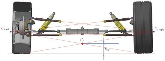
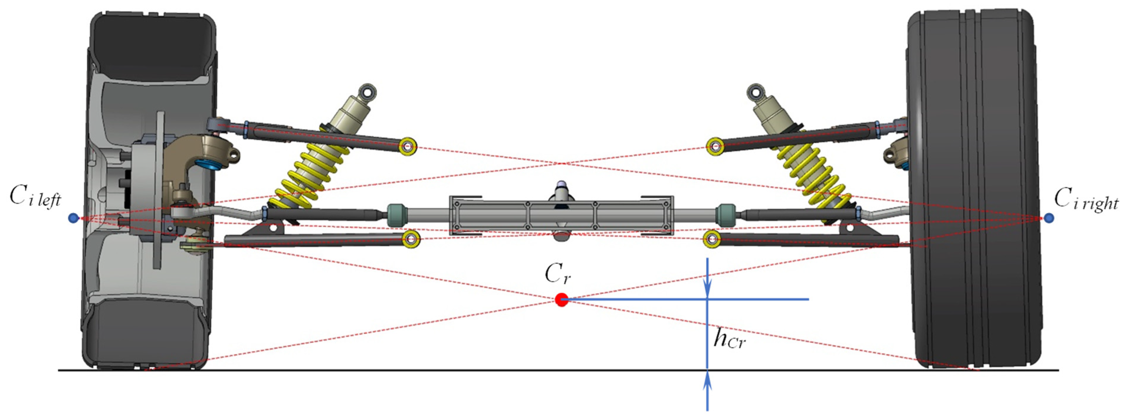
Furthermore, the roll center position for any suspension system is physically determined by the configuration, shape, position, and dimensions of its structural elements. For illustration, Figure 1 shows the general case of a double-wishbone suspension [6,7,8,9]. This type is most common in sports or off-road vehicles due to its high configurability. The Cr position is determined as follows: extending the directions of the left control arms leads to an intersection at a point called the instantaneous center (). Similarly, the right control arms intersect at . By drawing a line from the center of the left tire contact patch to and another from the right contact patch to , the intersection of these lines defines the axle’s roll center.
Figure 1.
Determination of the Cr position for a double-wishbone suspension—adapted from [6,7,8,9].
The purpose of the figure is therefore limited to showing how the roll center position is obtained from the suspension link geometry, namely through the construction of the relevant lines associated with the upper and lower control arms and the resulting intersection used to define the roll center location and height. In this sense, the figure is meant to support the kinematic/geometric explanation only, and not to represent the complete dynamic behaviour of the axle or vehicle.
Evidently, the positions of these critical virtual points should be established before the design process of the suspension system and chassis begins. The geometric dimensioning of suspension components (knuckle length, pivot positions, arm orientation, hardpoint locations on the frame, etc.) must be executed such that the resulting roll center is in the correct position required by the vehicle dynamics.
The existing practice typically combines suspension kinematics, tire models, and multibody vehicle simulations to assess handling behavior after a geometry is already available. The proposed contribution is complementary rather than competitive with MBD tools: it provides a simple iterative design-stage method to identify correlated front/rear roll center targets before detailed geometry modeling, numerical optimization, or full-vehicle simulation is undertaken.
The paper presents an iterative procedure, based on real tire data, which allows for the selection of target roll center heights during the preliminary design phase to ensure adequate dynamic behavior. The final solution must then be selected by considering technological constraints, thereby avoiding geometrically impossible or difficult-to-manufacture designs.
The primary advantage of this method is the correlation it provides between the roll center positions of the two axles.
The process is based on two fundamental premises:
In any steady-state turn, each axle must follow a circular trajectory of a given radius. To achieve this, the lateral grip forces generated by the two wheels must equal the centrifugal force corresponding to the mass distributed to that axle. It is assumed that if this condition is satisfied at the maximum performance limit (maximum lateral acceleration), it will also be satisfied at lower regimes.
The vehicle should exhibit neutral handling, meaning it should not possess an inherent tendency to understeer or oversteer.
These two conditions are detailed in the following sections.
2. Theoretical Foundations and Methodology
2.1. Lateral Force Equilibrium
During steady-state cornering, the centrifugal force associated with the mass distributed to an axle is balanced by the sum of the lateral grip forces developed at the tire contact patches of that axle:
where is the lateral grip force of the inner wheel and is that of the outer wheel.
In practice, the dependence of the lateral force on the vertical wheel load is provided experimentally by the tire manufacturer in the form of curves shown in Figure 2, known as tire slip characteristics [9,10]. The notation adopted throughout this study is based on the SAE vehicle coordinate system. The x-axis is oriented forward along the vehicle longitudinal direction, the y-axis laterally, and the z-axis vertically. The quantities Y and Z used in the tire-force plots denote the lateral force and vertical load, respectively, within this convention.
Figure 2.
Tire slip characteristics.
Lateral forces depend on the vertical load (Z) and the slip angle ()—the angle between the wheel’s longitudinal plane and its actual direction of travel.
As observed in the figure, lateral grip increases non-linearly with vertical load and is significantly influenced by the slip angle [9,11]. For a given vertical load, the lateral grip increases as the slip angle increases. This dependency can also be represented with the slip angle on the abscissa and the wheel load treated as a parameter.
In turn, the vertical load on each wheel of the axle depends on the dynamic load transfer during cornering, which is a function of the roll center position. For a specific roll center height, if the experimental tire slip characteristics are known, the lateral grip forces can be determined for any slip angle.
It can be concluded that in a given turn (provided the centrifugal force remains within reasonable limits), for any roll center position, there will be a specific slip angle at which the equilibrium Equation (1) is satisfied. Consequently, this condition alone is insufficient to establish a correlation between the roll center heights of the two axles. An additional method is required to constrain the slip angle values.
The proposed procedure is formulated for steady-state cornering at a prescribed target lateral acceleration and should therefore be interpreted as a quasi-steady preliminary design method. The equilibrium conditions are evaluated at a selected operating point, assuming constant cornering conditions, rather than through transient or instantaneous vehicle response. This distinguishes the present approach from full multibody simulation tools such as Adams or Simpack, which can resolve the instantaneous dynamics of a fully defined vehicle model but are typically applied after the suspension geometry has already been specified. In the present work, the method is intended for the earlier design stage, where correlated front and rear target roll center heights must be identified before detailed hardpoint definition and subsequent MBD validation. In addition, the tire characteristics used in the demonstrator case correspond to 0° camber; therefore, the obtained solution should be regarded as a preliminary result for this simplified condition, to be further refined once camber variation is incorporated into the suspension design process.
2.2. Ackermann Geometry and the Distinction Between Kinematic and Dynamic Steering
This additional constraint can be derived from the neutral handling condition. Ideally, a vehicle should negotiate a steady-state curve (constant radius at constant speed) without exhibiting understeer or oversteer tendencies.
In low-speed cornering (maneuvering), dynamic effects are negligible; the turn is dictated by kinematic considerations, and the kinematic steer angle () is chosen to follow (approximately) the Ackermann geometry [4,12,13].
Conversely, when cornering at high speeds, the motion is dictated by dynamic factors [1,2,4,7]. The front axle must be steered by the driver such that the wheels achieve a slip angle () sufficient to generate the required lateral grip. In this context, the steering angle of the directed wheels is referred to as the dynamic steer angle (θ).
It must be noted, however, that lateral grip force only arises in the presence of a slip angle. This implies that the rear axle wheels must also travel at a slip angle () sufficient to generate a lateral grip force that equals the centrifugal force generated by the rear axle mass. The rear axle slip angle cannot be directly controlled by the driver’s steering input. Instead, it emerges as the vehicle adjusts its attitude on the trajectory through an imperceptible outward drift of the rear wheels, accompanied by an increase in the slip angle until the necessary value is reached.
The difference between the dynamic steer angle (θ) and the kinematic steer angle () is defined as the understeer gradient. Depending on the vehicle’s dynamic character, three scenarios may occur:
- : The vehicle exhibits understeer, meaning a larger dynamic steer angle was required to complete the turn.
- : The vehicle exhibits oversteer, meaning the required dynamic steer angle was smaller than the kinematic one.
- : The vehicle exhibits neutral handling, which is the optimal condition a designer should aim for when dimensioning the suspension system.
The understeer gradient can be mathematically expressed as a function of the axle slip angles as follows [4,7]:
where and are the slip angles of the front (anterior) and rear (posterior) axles, respectively.
For neutral behavior:
In other words, for neutral cornering behavior, the wheels of both axles must operate at equal slip angles:
It follows that for stable and neutral steady-state cornering, the following conditions must be simultaneously satisfied:
where the subscripts a and p refer to the front and rear axles, respectively.
The first two equations represent the equilibrium conditions, while the last one represents the neutrality condition.
2.3. Input Data and Test Conditions: Demonstrator Vehicle Parameters
To illustrate the application of this methodology, we present the determination of a suitable pair of roll center heights for a Formula Student racing car. The design process for such a vehicle is heavily influenced by the technical constraints and safety requirements imposed by the competition regulations [14]. This type of vehicle employs a double-wishbone suspension system for both axles, due to the constraints imposed by the competition regulations, as well as its high degree of configurability. Suspension optimization remains a critical factor in the performance of a Formula Student racing car [15,16,17] and the roll center position, which is determined by the configuration and dimensions of the structural elements [5,6,13,18], plays a crucial role in the process.
The car is characterized by the following parameters:
- Total mass: m = 325 kg;
- Sprung mass: = 258 kg;
- Wheelbase: L = 1950 mm;
- Front track width: = 1250 mm;
- Rear track width: = 1250 mm;
- Center of gravity (CoG) height: = 350 mm;
- Distance from CoG to front axle: = 1065 mm;
- Distance from CoG to rear axle: = 885 mm.
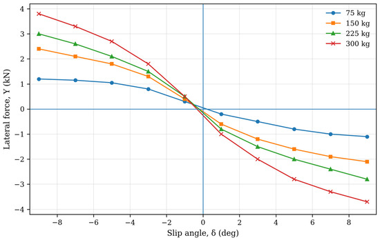
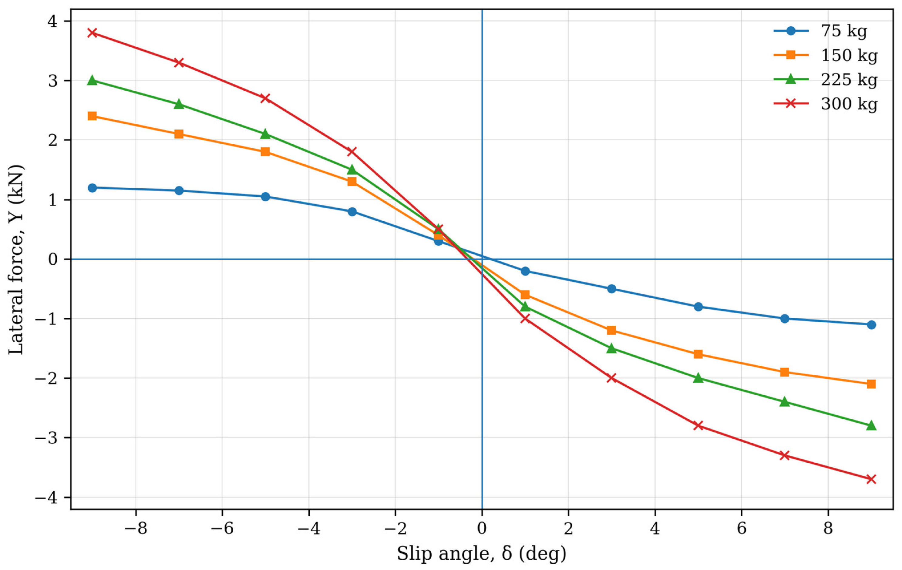
The vehicle is equipped with AVON 6.2/20.0-13 tires. At a pressure of 1.45 bar, the grip performance for these tires was derived from experimental Formula SAE-type tire datasets [19] and from the specific Avon manufacturer dataset used by the authors (manufacturer data sheet, on file with the authors). Data are shown in Figure 3. Since the primary objective of this work is to present the calculation method, experimental data from Figure 3 are used, although they were measured at a 0° camber angle. In practice, this calculation should be preceded by a preliminary design stage to estimate the actual camber angle during the target cornering maneuver.
Figure 3.
Lateral force vs. slip angle for AVON 6.2/20.0-13 tires at 0° camber, based on manufacturer test data and Formula SAE-type datasets (author-generated representation) [19].
It should be emphasized that the tire characteristics used in this study were obtained at 0° camber and were employed here to illustrate the proposed calculation procedure under a simplified operating condition. Therefore, the resulting front–rear roll center correlation should be regarded as a preliminary design outcome rather than a final suspension specification. In practical vehicle development, camber variation caused by suspension kinematics and body roll should be included in tire force evaluation, as it affects the lateral force generation of the tires and may modify the neutral handling solution.
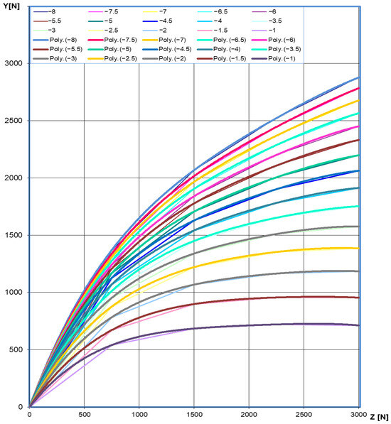
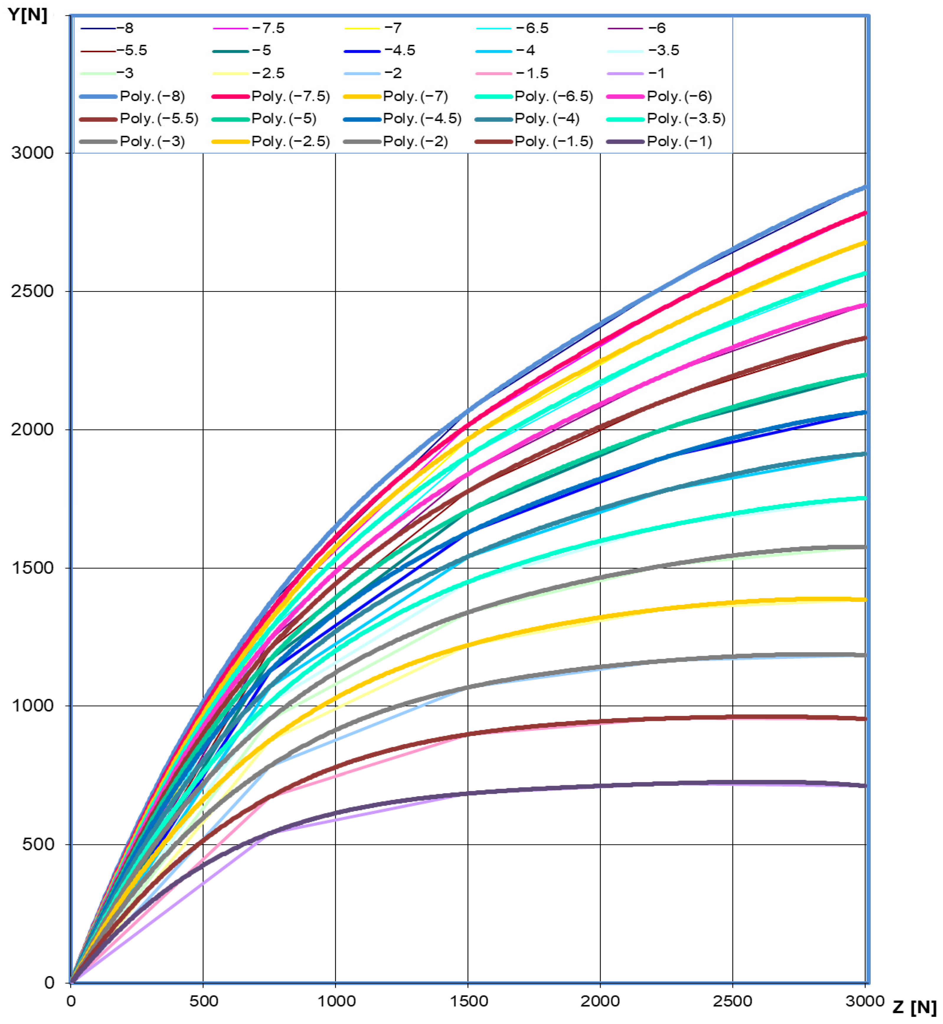
The data shown in Figure 4 are experimental tire measurements taken from literature sources and from the manufacturer-provided dataset used by the authors. The load values are expressed in kgf-equivalent form and represent vertical wheel load, rather than vehicle mass directly. For high-performance racing slick tires, the measured lateral force may exceed the corresponding vertical load because the effective tire-road friction coefficient can be greater than 1 under test conditions.
Figure 4.
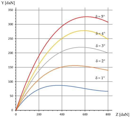
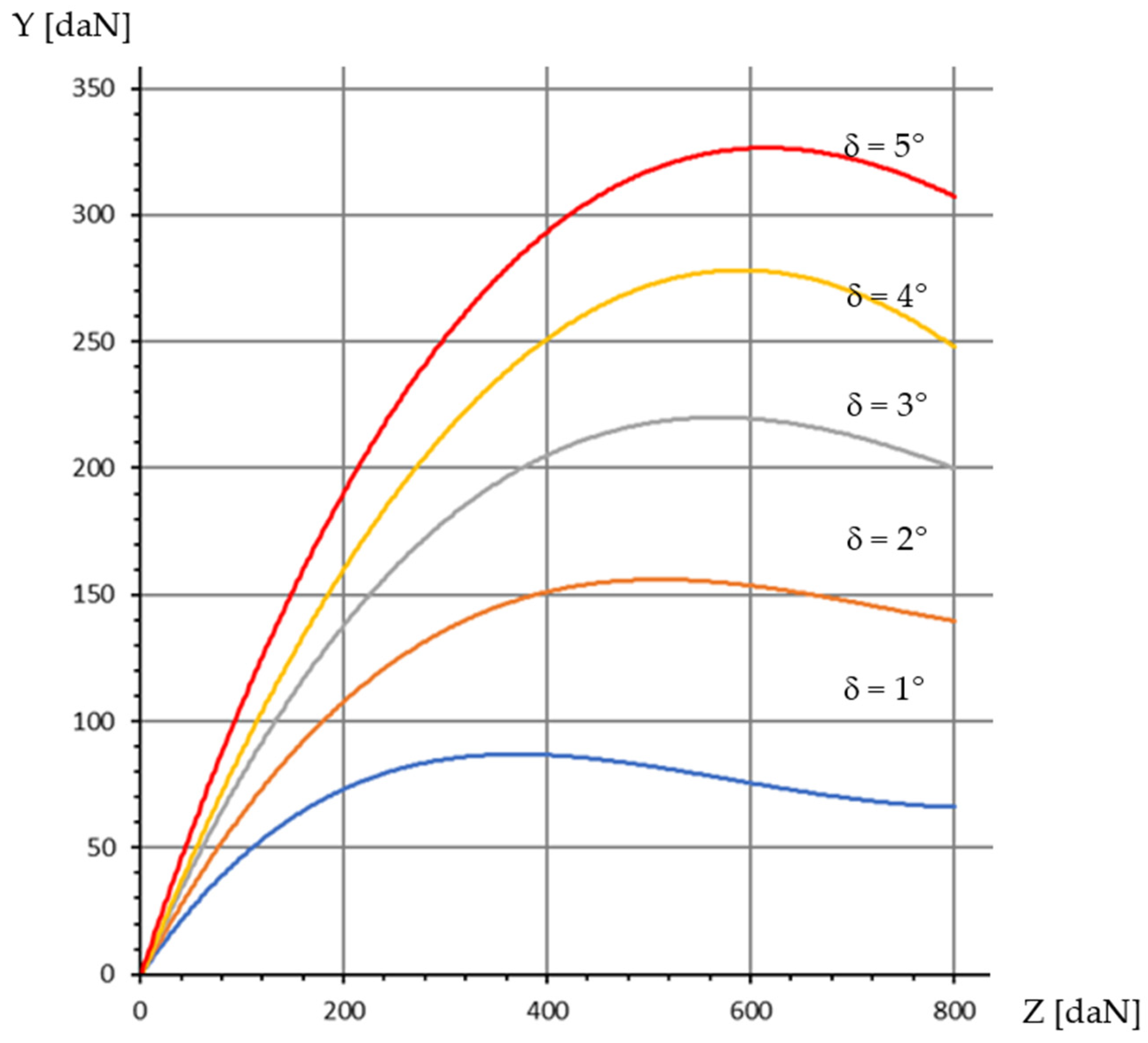
Interpolation of experimental grip data used in this study (author-generated figure based on the datasets described in the text) [19].
The slight asymmetry of the curves with respect to positive and negative slip angles reflects the use of raw experimental data rather than an idealized analytical tire model. Such asymmetry may result from measurement conditions, experimental scatter, tire construction effects, and the geometry of the test setup, including the position of the pivot axis relative to the tire contact patch.
The curves in Figure 3 illustrate the dependence of lateral grip force on the slip angle, parameterized by vertical wheel load. Because the discrete variation in vertical load is impractical for iterative calculation, these curves were transposed into those shown in Figure 4, where lateral force is plotted against vertical load with the slip angle as a parameter. These curves were then interpolated using fourth-degree polynomial functions. The interpolation curves are overlaid in the same figure.
To verify the equilibrium conditions in Equation (5), both centrifugal forces and the lateral grip forces for each individual wheel must be estimated. Consequently, vertical wheel loads must be determined, which, as previously noted, depend on the roll center positions.
2.4. Lateral Force Equilibrium Conditions
2.4.1. Target Lateral Acceleration
The first step is to establish a performance target for the vehicle. The fundamental parameter for estimating cornering performance is the maximum sustained lateral acceleration, rather than speed. Since the speed at which a curve can be negotiated depends on the radius, speed is not a limiting parameter. Therefore, a target maximum lateral acceleration of is imposed, consistent with typical values achieved in Formula Student competitions [15,16,20].
In addition, it should be noted that, in a real suspension system, roll center positions vary with suspension deflection and body roll, and therefore indirectly with lateral acceleration. In the present formulation, these effects are not explicitly modeled, as the roll center heights are treated as design parameters corresponding to a reference operating condition.
2.4.2. Axle Mass Distribution and Centrifugal Forces
The total mass distributed to each axle is determined by:
Similarly, for the sprung masses:
The centrifugal forces for each axle during steady-state cornering are:
2.4.3. Dynamic Load Transfer
The dynamic load transfer for the front and rear axles is described by [1,4,7,11]:
where:
- : Load transfer on the front and rear axles, respectively;
- , : Front and rear track widths;
- , : Front and rear roll center heights;
- , : Front and rear axle roll stiffness;
- H: Distance between the center of gravity and the roll axis;
- M: Total vehicle mass;
- g: Gravitational acceleration.
2.4.4. Roll Stiffness Initialization
Besides the roll center heights ( and ), the only unknowns in Equations (10) and (11) are the roll stiffnesses and . To initialize these values, a maximum chassis roll angle limit of 1.7° was imposed for the target turn:
2.4.5. Dynamic Vertical Wheel Loads
By knowing the parameters in Equations (10) and (11), the dynamic load transfer from the inner to the outer wheel can be determined. Starting from the static wheel loads, the dynamic vertical load for each wheel is calculated:
where subscripts “i” and “e” denote the inner and outer wheels, respectively.
2.4.6. Lateral Forces and Equilibrium Verification
Using the curves in Figure 4, the lateral grip forces for each wheel can be calculated. These curves represent the lateral force as a function of vertical load, using the slip angle as a parameter (ranging from 1° to 8° in 0.5° increments). To obtain a mathematical expression, the curves were interpolated using fourth-degree polynomials, which were found to describe the dependency with the highest accuracy. The interpolation functions for each analyzed slip angle are presented in Table 1.
Table 1.
Interpolation relations for tire grip curves.
Based on these interpolation functions and the calculated dynamic vertical loads, the lateral grip forces can be determined for each slip angle in the analyzed set:
Subsequently, the total lateral grip forces generated by each axle are:
The resultant lateral force acting on each axle is defined as the difference between the centrifugal force and the generated grip force:
To satisfy the equilibrium conditions in Equation (5), these resultant forces must be zero.
2.5. Neutrality Condition
By plotting the resultant forces from Equations (21) and (22) against the slip angle, curves similar to those in Figure 5 are obtained. These curves intersect the abscissa at a specific slip angle, which can be determined graphically. This value represents the required slip angle for the axle to achieve equilibrium during the considered turn.
Figure 5.
Resultant lateral forces per axle.
To satisfy the neutrality condition in Equation (5), the slip angle values at which these curves intersect the abscissa must be identical for both the front and rear axles.
The neutrality condition is solved through a guided iterative graphical search in which the front and rear roll center heights are successively adjusted until the equilibrium slip angles of the two axles become equal. Convergence is evaluated based on the alignment of the zero-crossings of the front and rear resultant lateral-force curves.
For each selected pair of front and rear roll center heights, the resultant lateral-force curves of both axles are computed, and their zero-crossings are identified, yielding the corresponding equilibrium slip angles. The difference between these slip angles defines the neutrality error for the current iteration.
If a mismatch exists, the roll center heights are adjusted in the direction that reduces this error, and the calculation is repeated until the front and rear equilibrium slip angles coincide within the graphical resolution of the method.
This approach is implemented as a guided graphical search rather than as a formal numerical optimization algorithm. Accordingly, it does not employ gradient-based, stochastic, or evolutionary methods, but instead follows a successive-correction procedure intended for preliminary design. The following section describes the application of this procedure for the proposed demonstrator vehicle.
3. Description of the Procedure
The iterative procedure follows a structured successive-correction logic, starting from an initial physically feasible pair of front and rear roll center heights. For this configuration, the roll-axis geometry, axle roll stiffnesses, load transfer distribution, and dynamic wheel loads are evaluated, allowing the construction of the resultant lateral-force curves for both axles.
The equilibrium slip angle of each axle is identified from the condition of zero resultant lateral force. The difference between the front and rear values serves as an indicator of the vehicle’s deviation from neutral behaviour.
Based on this deviation, the roll center heights are adjusted in a direction consistent with the observed handling tendency. In the demonstrator case, a larger equilibrium slip angle at the rear axle—corresponding to an oversteer tendency—was corrected by increasing the front roll center height and decreasing the rear roll center height in the subsequent iteration.
This correction process is repeated until a balanced condition is achieved within the graphical accuracy of the method, yielding a consistent set of correlated roll center heights suitable for preliminary design assessment.
The procedure consists of the following steps:
- Initial Iteration: Two arbitrary values for the roll center heights are selected, ensuring they are physically attainable. For example:= 150 mm;= 100 mm.
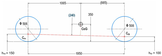
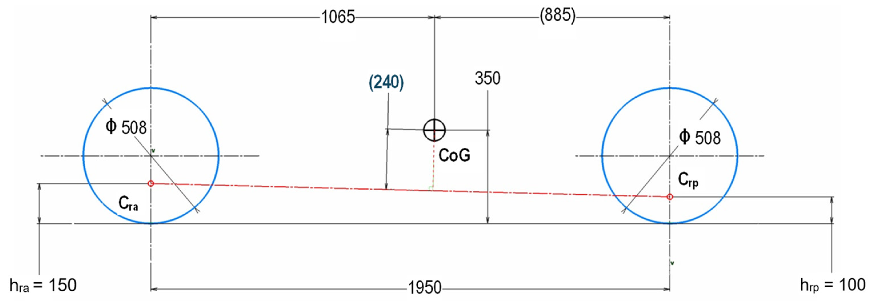
- Roll Axis Geometry: The distance between the roll axis and the vehicle’s center of gravity is determined. The CoG position and the roll axis are plotted in a 2D sketch as shown in Figure 6.
Figure 6.
Determination of the distance between the center of gravity and the roll axis. Cra and Crp denote the front and rear roll centers as geometric points, while hra and hrp denote their corresponding heights above ground level. In the present example, the front and rear roll center heights are hra = 150 mm and hrp = 100 mm, respectively.
From this 2D sketch, the required distance (marked in blue in Figure 6) is measured. In this case, H = 240 mm.
- Performance Targets: A maximum lateral acceleration of and a maximum chassis roll angle of 1.7° are imposed.
- Stiffness and Forces: The axle roll stiffnesses (, ) required to maintain this roll angle are determined using Equations (12) and (13). Axle mass distributions and centrifugal forces are calculated via Equations (6)–(10).
- Load Transfer and Vertical Loads: The dynamic load transfer for each axle is determined using Equations (10) and (11), followed by the calculation of dynamic vertical loads for all four wheels (Equations (14)–(17)).
- Grip and Resultants: Using the interpolation functions from Table 1, the lateral grip forces for each tire (Equations (18) and (19)) and each axle (Equation (20)) are calculated for the entire slip angle range.
- Graphical Analysis: The resultant lateral forces for the front axle (Equation (21)) and rear axle (Equation (22)) are calculated and plotted against the slip angle. For the initial values in this example, the curves in Figure 7 are produced.
Figure 7.
Axle lateral forces vs. slip angle (First Iteration).
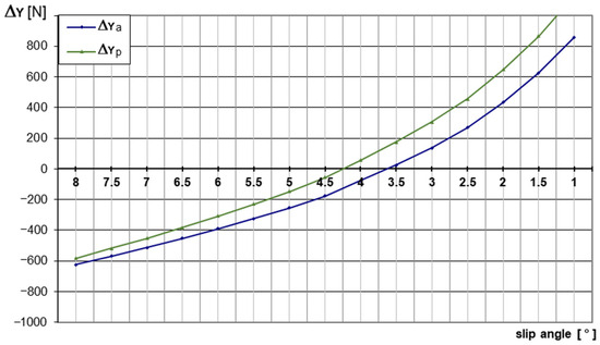
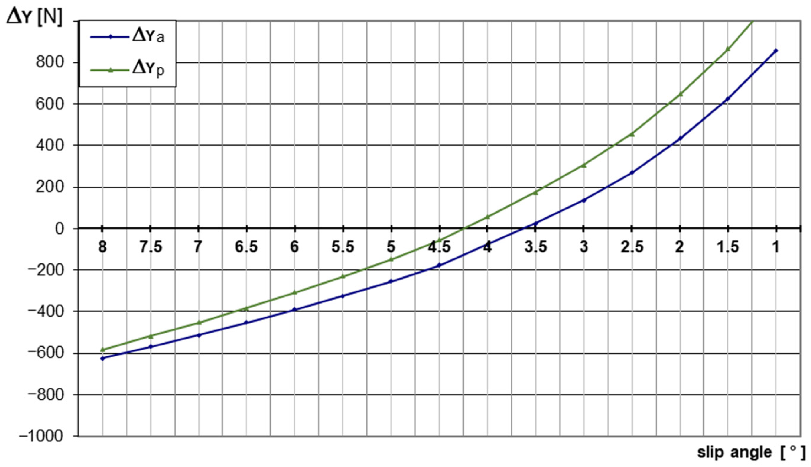
It is observed that the lateral forces for each axle reach zero at different slip angles. The front axle reaches equilibrium at approximately 3.65°, while the rear axle requires approximately 4.25°. Consequently, the understeer gradient (Equation (2)) is negative, indicating an oversteer characteristic.
- Subsequent Iterations: New roll center heights are selected to mitigate the oversteer tendency. In this case, the front roll center Cra is raised and the rear roll center Crp is lowered. All calculations and plots are updated.
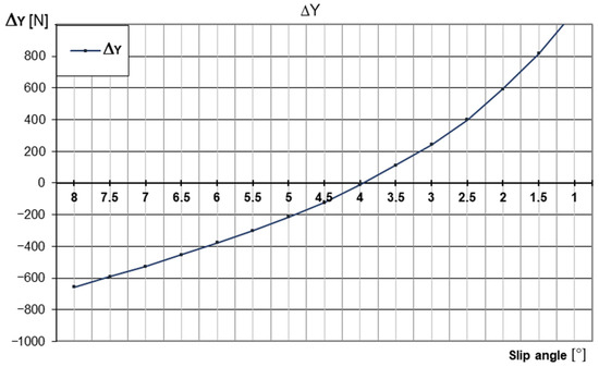
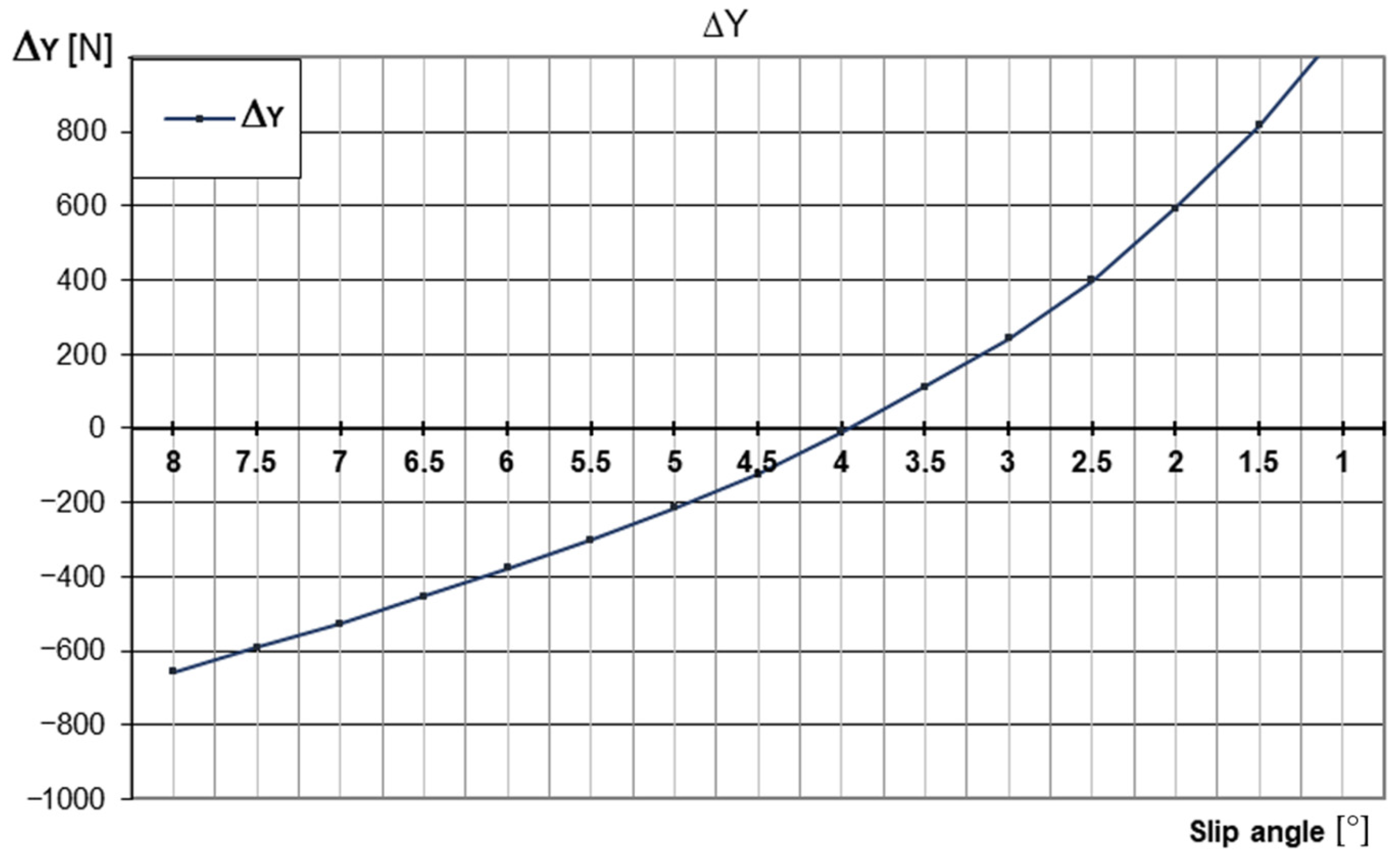
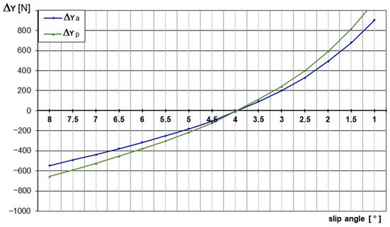
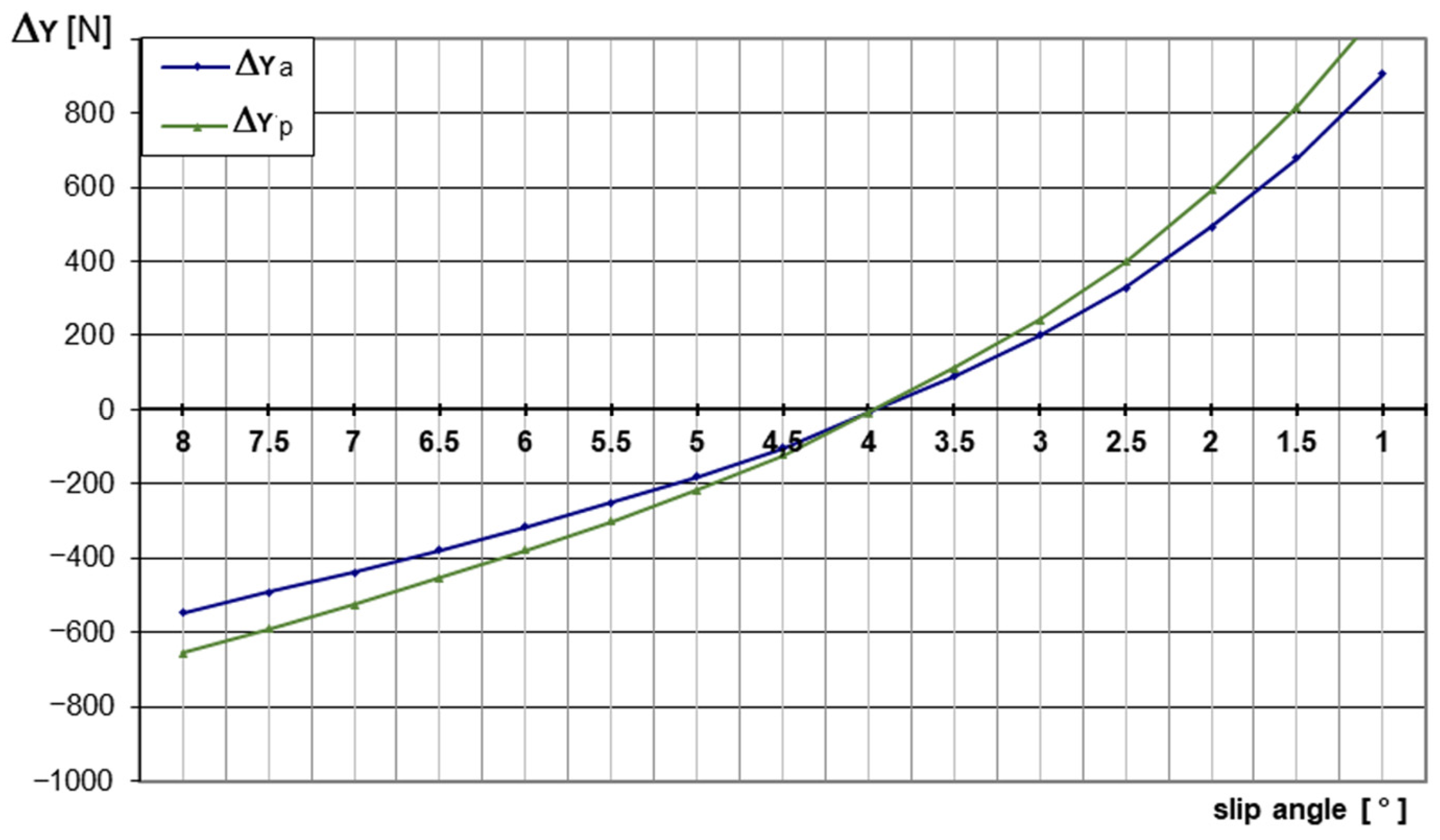
- Convergence: The process is repeated until the neutrality condition is met—when both curves intersect the x-axis at the same slip angle (Figure 8).
Figure 8.
Achievement of the neutrality condition.
The curves in Figure 8 were obtained for the following optimized roll center heights:
= 180 mm;
= 50 mm.
Several observations regarding these results are presented below.
4. Discussion
- Non-uniqueness of the solution: The solution presented above is not unique. The neutrality condition can be achieved through various combinations of roll center heights; however, these values are interdependent [8,21]. In this regard, the procedure provides a methodology for correlating the positions of the two roll centers rather than defining a single, fixed position.
- Practical feasibility: The procedure is highly effective for avoiding design solutions that are difficult or impossible to implement due to geometric constraints [5,12,13]. Furthermore, in cases where one roll center position is fixed or constrained by the suspension type—such as trailing arm or swing arm configurations—this method allows for the determination of the required position for the remaining roll center.
- Influence of roll stiffness: The results are influenced by the roll stiffness of the two axles. In the presented example, these values were evaluated by imposing a limit on the chassis roll angle. If the roll stiffness is generated solely by the suspension springs (in the absence of an anti-roll bar), passenger comfort may be compromised. However, the designer has the flexibility to adjust spring rates by incorporating anti-roll bars. Axle stiffness values can be adjusted as needed—achieving the same roll angle with a different combination of torsional stiffnesses [4,5,15,22]. Applying the described procedure in such cases will yield a different combination of roll center positions to maintain neutrality.
- Methodological principle: This work presents the fundamental principle of the method. Although the procedure may appear laborious, it can be easily automated by developing a simple computational script.
- Graphical convergence: In the presented approach, convergence toward the neutrality condition is evaluated graphically, which may introduce minor assessment errors. Nevertheless, even in its current form, the procedure serves as a valuable tool for the preliminary design of suspension components. Furthermore, if implemented into a computational program, convergence can be evaluated numerically, significantly reducing the potential for error.
- The present formulation assumes constant track width and fixed roll center positions. In practice, suspension kinematics and compliance may introduce variations in effective track width and roll center location during cornering. These effects, together with camber variation, influence load transfer and tire force generation, and are typically addressed in more advanced analyses such as multibody dynamics simulations.
5. Conclusions
The present work introduces a robust iterative methodology for correlating the roll center heights of a vehicle’s front and rear axles to achieve stable and neutral handling during steady-state cornering. Based on the analysis and the results obtained for the demonstrator vehicle, the following conclusions can be drawn:
- Interdependence of Design Parameters: The study demonstrates that roll center heights are not independent variables but are functionally correlated through the vehicle’s dynamic balance. The neutrality condition () can be satisfied by multiple pairs of (, ), offering the designer a “solution space” rather than a single fixed point.
- Integration of Experimental Data: By incorporating fourth-degree polynomial interpolation of real tire grip characteristics (AVON 6.2/20.0-13), the method bridges the gap between simplified theoretical models and the non-linear behavior of high-performance tires. This ensures that the calculated roll center positions remain valid at the target lateral acceleration of 1.2·g.
- Design Flexibility and Feasibility: A significant advantage of this approach is its ability to adapt to geometric or structural constraints. For suspension types with fixed roll centers (e.g., trailing arm or swing arm), the procedure allows for the precise determination of the required roll center height for the opposite axle to maintain directional stability.
- Influence of Roll Stiffness: The results highlight that the distribution of axle roll stiffness (, ) and the use of anti-roll bars are critical factors. Adjusting these stiffnesses allows for achieving the target roll angle while shifting the required roll center heights to more constructive geometric positions.
- Practical Utility in Preliminary Design: Although evaluated graphically in this paper, the procedure provides a clear roadmap for the initial dimensioning of suspension hardpoints. For the analyzed Formula Student vehicle, the convergent solution (hra = 180 mm; hrp = 50 mm; d = 4°) Provides a validated starting point for subsequent Multi-Body Dynamics (MBD) and Finite Element Analysis (FEA) simulations.
In summary, this iterative graph-analytical method serves as an efficient tool for suspension engineers, facilitating a balanced trade-off between geometric feasibility and optimal vehicle handling.
6. Future Work
To further refine and expand the applicability of the proposed methodology, the following research directions are recommended:
- Integration of Camber Effects: Future iterations of the model will incorporate the influence of camber angle variations on the tire grip curves. Optimizing the suspension kinematics to maintain negative camber on the outer wheel remains a critical step for maximizing lateral force generation [9,18,22].
- Numerical and Experimental Validation will be conducted to correlate theoretical slip angles with real-world performance, including a rigorous analysis of the tire–road interaction at high lateral accelerations [20,23,24,25,26]. This will provide a more detailed understanding of the non-linear effects on tire grip during extreme cornering maneuvers.
- Optimization of Roll Stiffness Distribution: A detailed sensitivity analysis of the roll stiffness ratio will be conducted. This includes the explicit modeling of anti-roll bar rates and their impact on steering response and transient roll behavior [15,18,22].
- Compliance and Structural Analysis: Future studies will account for the compliance of suspension bushings and the local stiffness of the chassis. These factors will provide the necessary load cases for a comprehensive Finite Element Analysis (FEA) of structural components such as control arms, uprights, and mounting points [17,18].
- Automation of the Computational Script: The current graphical convergence process will be transitioned into a fully automated numerical solver (e.g., in MATLAB R2015a—at least or Python 3.13), significantly reducing the margin for error and allowing for rapid “solution space” mapping during the early design stages.
Author Contributions
Conceptualization, M.B. and G.G.U.; methodology, M.B. and C.D.C.; software, G.G.U.; validation, E.R. and G.G.U.; formal analysis, C.D.C.; investigation, C.D.C.; data curation, G.G.U.; writing—original draft preparation, M.B.; writing—review and editing, M.B. and G.G.U.; supervision, E.R.; project administration, M.B.; funding acquisition, G.G.U. All authors have read and agreed to the published version of the manuscript.
Funding
This research is part of the project entitled “VEAINOV3D—Development of VEA MFG’s advanced innovation and production capacity in the customized medical prosthetics and automotive sector using 3D High-Tech”, SMIS code 338485, co-financed by the European Union through the North—East Regional Program 2021–2027 (Romania), part of European Regional Development Fund (ERDF). The implementation of this project is carried out by VEA MFG LTD—Lead Partner, in partnership with Iasi University of Life Sciences (IULS), contributing to the enhancement of innovation, competitiveness, and sustainable development in line with the Regional Smart Specialization Strategy—RIS3 North-East 2021–2027.
Data Availability Statement
The original contributions presented in this study are included in the article. Further inquiries can be directed to the corresponding authors.
Acknowledgments
During the preparation of this manuscript, the authors used Google Gemini (March 2024 version) for the purposes of technical translation from Romanian to English and linguistic refinement of the text. The authors have reviewed and edited the generated content as needed and take full responsibility for the content of this publication.
Conflicts of Interest
The authors declare no conflicts of interest. The funders had no role in the design of the study; in the collection, analyses, or interpretation of data; in the writing of the manuscript; or in the decision to publish the results.
References
- Gillespie, T.D. Fundamentals of Vehicle Dynamics; SAE International: Warrendale, PA, USA, 1992; pp. 173–195. [Google Scholar] [CrossRef] [Scilit]
- Jazar, R.N. Vehicle Dynamics: Theory and Application, 3rd ed.; Springer: New York, NY, USA, 2017; pp. 545–588. Available online: https://link.springer.com/chapter/10.1007/978-3-030-93220-6_1?utm_source=chatgpt.com (accessed on 22 March 2026).
- Guiggiani, M. The Science of Vehicle Dynamics; Springer: Dordrecht, The Netherlands, 2014; pp. 325–358. [Google Scholar] [CrossRef] [Scilit]
- Milliken, W.F.; Milliken, D.L. Race Car Vehicle Dynamics; SAE International: Warrendale, PA, USA, 1995; pp. 609–635. Available online: https://books.google.ro/books/about/Race_Car_Vehicle_Dynamics.html?hl=es&id=opgHfQzlnLEC&redir_esc=y (accessed on 23 March 2026).
- Bastow, D.; Howard, G.; Whitehead, J.P. Car Suspension and Handling, 4th ed.; SAE International: Warrendale, PA, USA, 2004; pp. 110–142. [Google Scholar]
- Dixon, J.C. The Roll-Centre Concept in Vehicle Handling Dynamics. Proc. Inst. Mech. Eng. Part D Transp. Eng. 1987, 201, 69–78. [Google Scholar] [CrossRef] [Scilit]
- Vilela, D.; Barbosa, R.S. Analytical Models Correlation for Vehicle Dynamic Handling Properties. J. Braz. Soc. Mech. Sci. Eng. 2011, 33, 437–444. [Google Scholar] [CrossRef] [Scilit]
- Sakai, H.; Satoh, Y. The Impact of Roll Center Height on Vehicle Dynamic Behavior. JSAE Rev. 1994, 15, 329–333. [Google Scholar] [CrossRef] [Scilit]
- Pacejka, H. Tire and Vehicle Dynamics, 3rd ed.; Butterworth-Heinemann: Oxford, UK, 2012; pp. 61–98. [Google Scholar]
- Kasprzak, E.M.; Gentz, D. The Formula SAE Tire Test Consortium—Tire Testing and Data Handling; SAE Technical Paper; SAE International: Warrendale, PA, USA, 2006. [Google Scholar] [CrossRef] [Scilit]
- Filipozzi, L.; Assadian, F.; Kuang, M.; Johri, R.; Velazquez Alcantar, J. Estimation of Tire Normal Forces including Suspension Dynamics. Energies 2021, 14, 2378. [Google Scholar] [CrossRef] [Scilit]
- Reimpell, J.; Stoll, H.; Betzler, J.W. The Automotive Chassis: Engineering Principles, 2nd ed.; Butterworth-Heinemann: Oxford, UK, 2001; pp. 380–410. [Google Scholar]
- Dixon, J.C. Suspension Geometry and Computation; Wiley: Chichester, UK, 2009; pp. 245–282. [Google Scholar] [CrossRef] [Scilit]
- Formula Student Germany. Formula Student Rules 2026, Version 1.1; FSG: Hockenheim, Germany, 2025. Available online: https://www.formulastudent.de/fsg/rules (accessed on 3 March 2026).
- Balena, M.; Mantriota, G.; Reina, G. Dynamic Handling Characterization and Set-Up Optimization for a Formula SAE Race Car via Multi-Body Simulation. Machines 2021, 9, 126. [Google Scholar] [CrossRef] [Scilit]
- Samant Saurabh, Y.; Kumar, S.; Jain, K.K.; Behera, S.K.; Gandhi, D.; Raghavendra, S.; Kalita, K. Design of Suspension System for Formula Student Race Car. Procedia Eng. 2016, 144, 1138–1149. [Google Scholar] [CrossRef] [Scilit]
- Țoțu, V.; Alexandru, C.; Tache, A.; Enache, S. Multi-Criteria Optimization of an Innovative Suspension System for Formula Student Racing Car. Appl. Sci. 2021, 11, 4167. [Google Scholar] [CrossRef] [Scilit]
- Gao, J.; Wu, F. Analysis and Optimization of the Vehicle Handling Stability with Considering Suspension Kinematics and Compliance Characteristics. Adv. Mech. Eng. 2021, 13, 16878140211015523. [Google Scholar] [CrossRef] [Scilit]
- Avon Tyres. Tire Test Results: 6.2/20.0-13 Slick Compound Data Sheet; Cooper Tire & Rubber Company: Melksham, UK, 2020. [Google Scholar]
- Palanivendhan, M.; Joshua Paul, E.; Philip, J.; Tiwari, M.; Sasikumar, S. Steady State Dynamic Analysis and Testing of an FSAE Vehicle. Mater. Today Proc. 2021, 45, 6987–7000. [Google Scholar] [CrossRef] [Scilit]
- Zhang, X.; Yan, Y.; Guo, K.; Yang, Y.; He, G. Vehicle Roll Centre Estimation with Transient Dynamics via Roll Rate. Veh. Syst. Dyn. 2022, 60, 699–717. [Google Scholar] [CrossRef] [Scilit]
- Kwon, S.-J.; Kim, T.-L.; Kim, C.-J. Optimal Selection of Suspension and Tires for Vehicles’ Cornering Performance. Machines 2022, 10, 1032. [Google Scholar] [CrossRef] [Scilit]
- Cao, D.; Song, X.; Ahmadian, M. Editors’ Perspectives: Road Vehicle Suspension Design, Dynamics, and Control. Veh. Syst. Dyn. 2011, 49, 3–28. [Google Scholar] [CrossRef] [Scilit]
- Yoo, S.-S.; Kim, P.-A.; Lee, H.-S. Load-Sensitive Tire–Road Friction Modeling and Dynamic Stability Analysis of Multi-Axle Trucks. Appl. Sci. 2025, 15, 12269. [Google Scholar] [CrossRef] [Scilit]
- Chen, J.; Wang, R.; Liu, W.; Sun, D.; Jiang, Y.; Ding, R. A Review of Recent Advances in Roll Stability Control in On-Road and Off-Road Vehicles. Appl. Sci. 2025, 15, 5491. [Google Scholar] [CrossRef] [Scilit]
- Borowski, J.; Emsmann, H.; Kneule, J.; Ruess, R.; Rudolph, S. Managing Design Variants in Formula Student Race Cars: A Digital Engineering Approach Across Multiple Teams. Vehicles 2026, 8, 43. [Google Scholar] [CrossRef] [Scilit]

Disclaimer/Publisher’s Note: The statements, opinions and data contained in all publications are solely those of the individual author(s) and contributor(s) and not of MDPI and/or the editor(s). MDPI and/or the editor(s) disclaim responsibility for any injury to people or property resulting from any ideas, methods, instructions or products referred to in the content. |
© 2026 by the authors. Licensee MDPI, Basel, Switzerland. This article is an open access article distributed under the terms and conditions of the Creative Commons Attribution (CC BY) license.