


Abstract
Low-pressure cold spray (LPCS) and medium-pressure cold spray (MPCS) provide field-deployable alternatives to stationary high-pressure cold spray (HPCS) for lightweight metallic component repair, although lower particle velocities and narrower process windows restrict the range of compatible repair materials. This review evaluates portable LPCS and MPCS repair as a distinct class of cold spray application using HPCS as the reference baseline. The article synthesises evidence on process windows, critical velocity, particle velocity ratio, deposition efficiency, deposit build-up capability, substrate preparation, porosity, oxide disruption, ceramic-assisted densification, interfacial bonding mechanisms, adhesion strength, hardness, residual stress, tensile behaviour, and fatigue performance. Attention is given to repair geometry, including blend-out depth, taper angle, aspect ratio, spray angle, and stand-off distance, because these factors govern particle impact conditions and interfacial integrity across practical repair geometries. Available evidence indicates that LPCS can achieve dimensional restoration, surface protection, and, in some cases, fatigue performance comparable with that of the substrate. However, structural qualification remains constrained by limited portable system fatigue data, few direct LPCS–MPCS comparisons under equivalent conditions, and inconsistent reporting of powder characteristics, surface preparation, porosity, and repair geometry. MPCS may extend the range of compatible repair materials while maintaining field deployability, but its peer-reviewed evidence base remains limited. Future work should prioritise controlled LPCS–MPCS comparisons, geometry-sensitive fatigue testing, standardised deposit quality metrics, and qualification procedures linking process window control with repair integrity.
1. Introduction
1.1. Background
Metallic components in aerospace, naval, energy, and other critical engineering sectors undergo complex service degradation involving interacting mechanisms such as fatigue, corrosion, and wear. These degradation processes can result in crack development, surface degradation, and material loss, limiting component reliability and service life. Rising acquisition costs, extended service intervals, and an ageing equipment population have increased the need to restore such components in service instead of replacing them. Deposit integrity is used here to denote the adhesion, cohesion, dense build-up, and residual stress state a deposited layer requires to restore load-carrying capacity under static and fatigue loading, a more demanding criterion than that commonly applied in the thermal spray literature, where deposit performance often denotes corrosion protection or dimensional restoration without structural load transfer [1,2].
Fusion-based repair routes such as weld overlay, laser cladding, and arc-based directed energy deposition can restore damaged material; however, their thermal input may alter the original material properties by introducing a heat-affected zone (HAZ), oxidation, phase transformations, precipitate dissolution, and tensile residual stresses, potentially reducing performance relative to the original microstructure and heat treatment condition. In the precipitation-hardened 7xxx-series aluminium alloys used in aerospace primary structure, hot cracking susceptibility and HAZ strength reductions of 30–50% are significant structural concerns [3,4]. Bonded composite patches are well-established for thin panel repairs but exhibit time-limited adhesive durability, moisture sensitivity, and geometric incompatibility with curvature surfaces [2]. Mechanical fastening via bolted doublers or rivet repairs introduces stress concentrations at fasteners, potentially seeding the fatigue damage the repair was intended to address [5].
Cold spray, invented at the Institute of Theoretical and Applied Mechanics in Novosibirsk in the 1980s and now deployed commercially in aircraft maintenance and naval ship repair [6], has emerged as an alternative. Depositing metal particles in the solid state without bulk melting preserves substrate temper, avoids HAZ formation, and generates residual stresses that are compressive or of manageable magnitude [7]. It has been used to restore corroded aluminium and magnesium airframe features to dimensional tolerance [8], and defence maintenance organisations have reported operational capability for aircraft outer-panel and rotorcraft component repairs [9,10]. Despite this, research has developed along two disconnected tracks: laboratory characterisation under idealised conditions using mostly high-pressure equipment and a smaller set of operationally focused field case studies, leaving engineers without a coherent framework for portable system selection.
Cold spray spans a range of pressure–temperature–velocity regimes with markedly different deposition behaviour. High-pressure cold spray (HPCS), operating up to 7.5 MPa with nitrogen or helium, offers the widest material compatibility and highest deposition efficiency but demands infrastructure that renders the equipment effectively stationary [11,12]. Low-pressure cold spray (LPCS), operating below 1 MPa with compressed air or nitrogen and downstream powder injection (Figure 1), is generally portable, weighing less than 30 kg [13,14], but its constrained velocity envelope limits deposition to ductile metals and composite feedstocks [15]. Medium-pressure cold spray (MPCS), an emerging intermediate class operating up to 3 MPa, likewise uses downstream injection and remains field deployable [16]. The two portable regimes differ by more than nominal pressure. The higher stagnation pressure and gas temperature of MPCS raise particle velocity (up to 800 m/s against 300–600 m/s of LPCS) and hence the velocity ratio (Section 3), which governs interparticle bonding and the accessible material set. LPCS is therefore limited to ductile, low-density metals and metal–ceramic composites, whereas MPCS reaches higher-strength Ti- and Ni-based alloys at the cost of heavier equipment and a nitrogen supply. Data for portable MPCS remain sparse.
Figure 1.
Schematic illustration of (a) high-pressure cold spray (HPCS) with upstream powder injection and (b) low-pressure cold spray (LPCS) system configurations. Medium-pressure cold spray (MPCS) shares the downstream configuration shown in (b), operating at higher stagnation pressure and gas temperature.
Deployment of portable cold spray requires four elements: (i) a process window framework accounting for the field constraints (variable spray angle, ambient temperature, substrate condition) that compress the operating margin above critical velocity; (ii) a microstructural understanding of porosity, oxide distribution, and interface bond continuity; (iii) a geometry-sensitive mechanical performance dataset generated on representative substrate flaws under portable deposition protocols, rather than the simplified coupons and HPCS conditions that dominate the literature; and (iv) a qualification framework linking process requirements to deposit acceptance criteria. Work towards the fourth requirement has begun. Stamoulis et al. [17] mapped the airworthiness requirements of the European Union Aviation Safety Agency (EASA), specifically Certification Specification CS-25 for large aeroplanes and Part 21, onto a defined set of established test methods and applied the resulting framework to the repair of a corroded AA6013-T6 wire bundle support bracket from a main landing gear bay using a portable medium-pressure Titomic D623 system. To the best of our knowledge, this is the only qualification and testing framework reported to date for a portable medium-pressure system.
This review examines the relationships between process, microstructure, mechanical properties, and repair performance for LPCS and MPCS. Earlier reviews either conflate the two regimes or treat MPCS as a variant of HPCS. Tregenza et al. [18] confirmed in their review of air-based cold spray that no prior review treats portable systems for surface engineering and repair as a unified topic. Three contributions are made here: substrate blend-out geometry is framed as a deposit integrity decision rather than a preparation detail; the sparse MPCS evidence base is documented in aggregated form as a qualification barrier; and HPCS is retained throughout as a reference baseline.
1.2. Review Methodology
The evidence relevant to portable cold spray is distributed across peer-reviewed research, published standards, and manufacturer and industry white papers. Literature was identified through Scopus for the period of 2000 to July 2026, combining process descriptors (“cold spray”, “low-pressure cold spray”, “medium-pressure cold spray”, “gas dynamic spray”, “portable cold spray”) with application terms (repair, deposition efficiency, adhesion, porosity, residual stress, fatigue, blend-out). However, terminology has evolved throughout the development of cold spray technology, and earlier studies do not always explicitly identify the process as low-pressure or medium-pressure cold spray. In many cases, the applicable pressure regime can only be determined from reported equipment specifications and operating pressure. Earlier publications may also describe related processes using terms such as kinetic spraying or supersonic particle deposition. Therefore, reference lists of retrieved articles were screened for studies the keyword search missed. Figure 2 summarises the process and eligibility criteria. Tabulated values throughout are compiled from studies differing in equipment, feedstock, substrate condition, and measurement protocol; they indicate the range reported for portable systems rather than controlled comparisons, and the limitation applying to each table is noted in its caption.
Figure 2.
Flowchart of literature review methodology and thematic synthesis.
The distribution of the retrieved literature is shown in Figure 3. Cold spray publications have increased substantially, from fewer than 10 articles annually in 2000 to approaching 400 articles per year by 2024–2025. Publications specifically addressing low-pressure cold spray emerged in the late 2000s; however, the available literature remains limited, with approximately 250 relevant articles identified compared with 4500+ publications retrieved for cold spray as a broader technology. The low-pressure share has remained close to 5% since 2013 and has not risen as the field has expanded, indicating that research on portable systems has developed at a slower rate than cold spray research overall.
Figure 3.
Annual publication output for cold spray in general and low-pressure cold spray from 2000 to July 2026 based on the selected bibliographic search terms. No publication was retrieved using the corresponding search term for medium-pressure cold spray; however, one paper has since been published reporting the use of a portable Titomic D623 medium-pressure cold spray system [17].
2. Fundamentals of Cold Spray
2.1. Process Overview and Bonding Mechanism
Cold spray is a solid-state additive deposition process in which metal powder particles, typically 5–50 μm in diameter, are accelerated through a converging–diverging (de Laval) nozzle to supersonic velocities in the range of 300–1200 m/s and impacted onto a substrate without bulk melting of either particle or substrate [7]. Because gas temperature is maintained well below feedstock melting points, cold spray avoids the extensive thermal exposure associated with fusion-based repair, thereby preserving the substrate alloy temper and feedstock microstructure while minimising oxidation and phase transformation, with residual stresses that are generally manageable and often compressive due to particle impact peening. These attributes distinguish it from flame, arc, and plasma spray processes.
When a particle impacts at or above a material-specific critical velocity, it undergoes extreme plastic deformation at strain rates in the order of 106–109 s−1. The deformation produces localised adiabatic heating at the particle–substrate interface, disrupts native oxide films, and establishes intimate metal-to-metal contact (Figure 4). The resultant bond combines mechanical interlocking, arising from the geometrical interpenetration of the deforming particle into surface asperities, with metallurgical continuity at regions where oxide disruption has occurred [19].
Figure 4.
Schematic representation of a cold-sprayed particle undergoing severe plastic deformation and forming a solid-state bond with a roughened substrate upon impact.
The dominant bonding mechanism has been the subject of sustained scientific debate. Assadi et al. [20] attributed bonding primarily to adiabatic shear instability (ASI) at the particle–substrate periphery, wherein the competition between strain rate hardening and thermal softening reaches an unstable threshold that expels interfacial oxides and enables metallurgical contact. Hassani-Gangaraj et al. [21] subsequently argued, based on laser-induced single-particle impact experiments, that hydrodynamic jetting driven by solid pressure waves, rather than ASI, is the primary mechanism of oxide expulsion and contact formation.
This interpretation was contested [22], and the counterargument was rebutted [23]. Both groups agree, however, on the existence of a well-defined critical velocity threshold and on the steep rise in deposition efficiency as particle velocity exceeds this threshold. This feature is of direct practical relevance to portable repair system design.
2.2. Classification of Cold Spray Systems
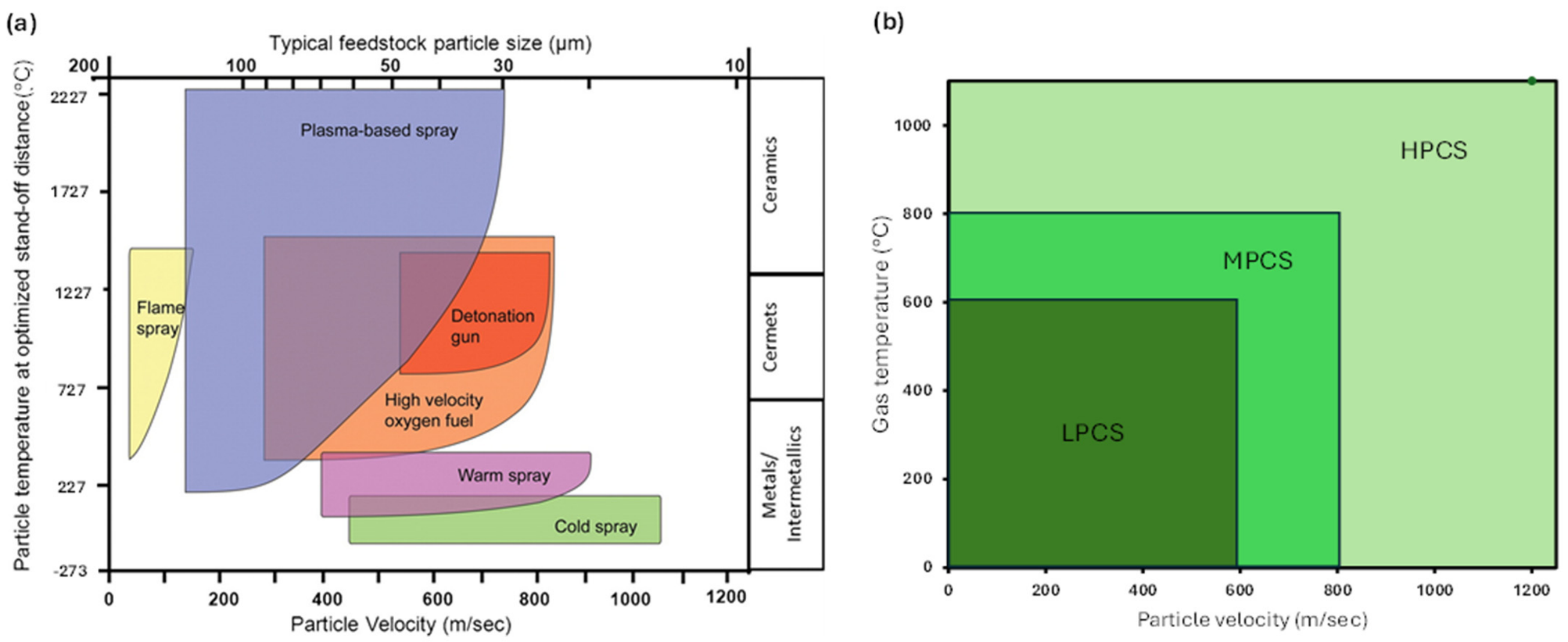
Cold spray systems are classified by their operating pressure, gas temperature, and powder injection architecture, portability, and operational mode (manual, mechanised, or automated). Eden et al. [24] presented one of the earliest classifications by injection method and operating regime (Figure 5), and Table 1 compares the three regimes against repair-relevant indicators. Increasing stagnation pressure and gas temperature raise attainable particle velocity from 300–600 m s−1 in LPCS to about 800 m s−1 in MPCS [16,25] and up to 1200 m s−1 in HPCS (Figure 6). This widens the processable material set from ductile metals and composite blends to high-strength alloys and steels and raises deposition efficiency from 5–30% to 70–95%. Field deployability moves in the opposite direction, from a 30 kg shop-air LPCS unit to HPCS equipment requiring three-phase power, a high-pressure compressor, and an acoustic enclosure: the characteristics that improve deposition capability also reduce portability.
Figure 5.
Classification of cold spray systems by powder injection mechanism and mode of operation. Upstream systems are typically HPCS, whereas downstream systems include MPCS and LPCS. Adapted from Eden et al. [24].
Table 1.
Process characteristics and repair-relevant attributes of low-pressure (LPCS), medium-pressure (MPCS), and high-pressure cold spray (HPCS) systems.
Figure 6.
(a) Classification of thermal and cold spray processes technologies as a function of particle temperature and velocity, adapted from Ahmed et al. [41], copyright 2021 Springer Nature (b) classification of cold spray regimes as a function of process gas temperature and particle velocity, showing LPCS, MPCS, and HPCS.
3. Process Windows and Deposition Boundary Conditions
3.1. Critical Velocity and the Deposition Threshold
The behaviour of portable cold spray systems is fundamentally governed by whether particles can be accelerated to an impact velocity that exceeds the material-specific critical velocity across the full repair surface, including zones of variable spray angle, varying stand-off distance, and changing substrate temperature inherent to field operations. Deposition occurs when the particle impact velocity exceeds the critical velocity :
One of the earliest quantitative formulations was proposed by Assadi et al. [20], who related critical velocity to material properties through a regression fit of finite-element impact simulations:
where is melting temperature, is particle impact temperature, is a reference temperature (293 K), is ultimate tensile strength, and is particle density. Although Equation (2) provides an initial engineering framework, it assumes limited variability in particle characteristics. Schmidt et al. [42] subsequently developed a more rigorous formulation based on the onset of localised severe plastic deformation accompanied by adiabatic shear instability (ASI) at the particle–substrate interface:
where is specific heat capacity and is a material-dependent fitting factor accounting for strain rate sensitivity. Particle size was also recognised to influence critical velocity:
where is particle diameter, is reference particle diameter, and is a material-dependent exponent. The predictive reliability of Equations (3) and (4) depends on Johnson–Cook constitutive descriptions extrapolated beyond experimentally validated strain rate regimes (103–104 s−1), introducing uncertainty for materials with limited high strain rate data. Wiehler et al. [43] demonstrated that gas-atomised aluminium and copper particles exhibit effective yield strengths approximately 81% and 43% higher than bulk material values, respectively, meaning that critical velocities estimated from bulk properties systematically underestimate the actual deposition threshold, a source of unconservative error in process window predictions for LPCS where velocity margins are already tight.
Assadi et al. [33] combined gas dynamic modelling with particle motion analysis and introduced a dimensionless velocity ratio as a compact indicator of deposition conditions. Particle acceleration in the nozzle is governed by a drag–force balance:
where Cd is the drag coefficient, and are gas and particle densities, and dp is particle diameter. The dimensionless velocity ratio is
The velocity ratio η defines a bounded window rather than a single threshold. Below η = 1, impact is too weak to disrupt the surface oxide, so particles rebound and deposition is negligible. Near η ~ 1, only the fastest particles exceed the critical velocity, making deposition highly sensitive to small process variations. Deposition efficiency peaks near η ≈ 1.5 [33]. Figure 7 maps these regimes against gas pressure, temperature, and particle size. Portable LPCS often operates close to the lower boundary, so it is the spatial uniformity of η across the repair surface, not its mean value, that determines whether continuous bonding is maintained at corners, curved surfaces, and regions of variable stand-off.
Figure 7.
Cold spray process–windows defined by the velocity ratio η, showing gas stagnation temperature To against (a) stagnation pressure po at a fixed particle diameter dp = 20 µm and (b) particle diameter dp at a fixed pressure po = 40 bar. The shaded region denotes optimal deposition near , while indicates no deposition and indicates erosion. Replotted from [33].
The models above were developed primarily for HPCS with upstream powder injection, where gas dynamic conditions approximate one-dimensional isentropic flow. For LPCS systems with downstream injection, Martínez-Flores et al. [32] derived an analytical model for particle acceleration in the diverging or downstream nozzle section:
This admits an analytical solution where is the theoretical velocity ceiling and characterises the system’s acceleration capability.
The model also accounts for particle deceleration in the free jet downstream of the nozzle exit, enabling stand-off distance effects to be parameterised. Its simplifying assumptions of one-dimensional isentropic flow, spherical geometry, constant , and ideal gas behaviour limit applicability to preliminary process design and regime comparison rather than quantitative field prediction.
3.2. Practical Implications for Deposition Quality
For primary structural repair, the objective extends beyond achieving deposition. The deposit must exhibit sufficient adhesion, cohesion, and dense build-up to restore load-bearing capability under the service conditions of the deposited component [44,45,46,47]. The process window is therefore not simply the threshold for deposition but the envelope within which deposited material contributes to load transfer and resists crack initiation and growth. Figure 8 illustrates how field variability through spray angle deviation, stand-off variation, and oxide or ambient effects progressively reduces the effective velocity ratio and compresses that envelope toward the deposition threshold.
Figure 8.
Schematic representation of the conceptual effect of increasing field variability on the effective velocity ratio (η) in cold spray. The introduction of field-related constraints (e.g., spray angle deviation, stand-off variation, and oxide/ambient effects) reduces the effective velocity ratio, compressing the usable deposition window toward the critical deposition threshold (η = 1), while the erosion limit (η = 2) remains the upper process boundary.
LPCS systems designed to minimise compressed air consumption and power demand typically produce particle velocities concentrated near the lower bound of the stable deposition regime [48]. Variations in stand-off distance, non-perpendicular spray angles imposed by access geometry or manual operation, and substrate temperature variability under ambient conditions collectively reduce effective particle impact velocity while potentially elevating the effective critical velocity through substrate work hardening and oxide growth. The net effect is a narrower operating margin in field repair than in laboratory characterisation, with systematically lower spatial uniformity.
Classical process window models do not account for surface oxide shells or the composite feedstocks commonly employed in LPCS to compensate for limited particle velocity [42]. For Al–Al2O3 composite feedstocks, the ceramic phase alters both the effective critical velocity and bonding behaviour in ways not captured by single-component formulations.
Ambient environmental variability constitutes a further, uncharacterised source of process window narrowing. Equipment manufacturer guidelines recommend ambient temperatures between 15 and 35 °C for stable deposition [48], but the structural consequences of operating outside of this range, particularly in marine environments with high humidity, salt contamination, and low substrate temperatures, have not been investigated systematically. Powder exposure to ambient humidity is known to degrade deposition efficiency, consistent with oxide thickening that raises the effective critical velocity [34]. This is a gap of direct operational significance for maritime and arctic deployment.
4. Deposition Efficiency and Build-Up Capability
4.1. Deposition Efficiency
Deposition efficiency (DE) is defined as the fraction of feedstock powder that successfully adheres to the substrate during spraying and is calculated from direct mass measurements:
DE is a direct indicator of process effectiveness and enables comparison across spray parameters, feedstock compositions, substrate conditions, and system configurations [49]. High DE indicates particles reaching sufficient velocity and plastic deformation for effective bonding and correlates broadly with lower porosity and stronger interparticle interfaces, but it does not by itself guarantee deposit quality, which also depends on powder morphology, gas dynamics, oxidation behaviour, substrate material type, and surface condition.
Optimising DE requires managing several interdependent variables: gas pressure and temperature, particle size, powder feed rate, spray angle, stand-off distance, and substrate preparation. Shorinov et al. [34] identified gas temperature and powder feed rate as the dominant variables governing DE in portable LPCS, with suboptimal conditions producing porous, weakly bonded deposits that cannot reliably transfer load. The same group later demonstrated the strength of this dependence by redesigning the integrated heater of a portable DIMET-405 unit from 3.3 to 5.3 kW, sustaining 605 °C at 1 MPa against 373 °C for the standard heater [50]. This increased the deposition efficiency of aluminium on titanium from 13.4% to 60.6% and the coating thickness more than fivefold under identical conditions.
Table 2 summarises representative DE values for LPCS. DE is improved by adding hard ceramic particles such as Al2O3 to ductile metallic powders to form metal–ceramic composite feedstocks [51,52]. Winnicki et al. [53] reported a 7.2% increase in DE when 50 wt% Al2O3 was added to a Cu matrix on AA1350. The improvement depends strongly on base powder morphology; however, dendritic electrolytic copper (E-Cu) outperformed spherical gas-atomised copper (S-Cu) under equivalent conditions, and ceramic addition modified both trends (Table 2). High ceramic fractions and powder recycling are in any case often impractical in the field owing to process instability, nozzle wear, and inconsistent powder delivery.
Table 2.
Representative values of deposition efficiency (DE) reported for LPCS systems for different powder–substrate combinations and process conditions.
Entries in Table 2 differ in propellant gas, stagnation pressure, and gas temperature. Because DE rises steeply once particle velocity exceeds the critical threshold, modest differences in these variables produce large changes in the reported value. Feedstock morphology acts independently, with dendritic and spherical copper sprayed under identical conditions in one study differing by more than fourfold [53]. Shorinov et al. [50] set out to maximise deposition efficiency, whereas the remaining entries report it incidentally under parameters selected for other endpoints. Direct comparison across the table is therefore not warranted.
Published data for HPCS report DE consistently exceeding 70% for copper and aluminium under optimised conditions [31]. Available commercial specifications for MPCS systems indicate a deposition rate of approximately 60 g/min [16].
4.2. Build-Up Capability and Structural Consequences
The structural implications of DE extend well beyond production economics. For LPCS, the combination of lower DE and lower deposition rate means that achieving millimetres of net material build-up for volumetric structural restoration requires a greater number of spray passes and longer cumulative dwell times over the repaired region [55]. Deforce et al. [47] recommended a minimum aluminium deposit thickness of at least 400 µm to ensure long-term barrier protection, establishing a practical lower bound for repair fill targets.
Traverse speed is a dominant kinematic variable governing build-up rate. Li et al. [56] showed for Cu + Al2O3 at 0.9 MPa nitrogen and 400 °C that reducing traverse speed from 200 to 50 mm/s increased deposit area per pass roughly fourfold (Figure 9), with lower porosity and near-linear scaling of deposited mass with pass count, as the denser particle flux raises both peening intensity and the probability of contacting each asperity. Seraj et al. [57] showed that for higher-strength materials, excessively slow traverse produces rebound-dominated erosion of previously deposited layers because thickening of the compressed gas layer beneath the spray spot reduces the normal component of impact velocity. Klinkov et al. [58] reported the same non-monotonic dependence for LPCS.
Figure 9.
Transverse thickness profiles of LPCS Cu + Al2O3 deposits at a constant stand-off distance of 5mm sprayed at gun traverse speeds (a) 50mm/s, (b) 100mm/s, (c) 150mm/s and (d) 200mm/s, each for 4, 8, 12, 16 passes. Peak thickness after 16 passes falls from approximately 1.15mm at 50mm/s to below 0.4mm at 200mm/s, while the profiles broaden and flatten, showing that slower traverse concentrates particle flux and raises build-up rate per pass. Replotted from [56].
Track spacing controls deposit cross-sectional uniformity through the degree of overlap between adjacent Gaussian deposit profiles. Tracks spaced too widely leave under-filled edge regions with systematic inter-track porosity; tracks spaced too narrowly accumulate heat and can cause localised work hardening that degrades bonding quality in subsequent passes.
The structural consequences are direct. Individual pass increments for LPCS are of the order of tens of micrometres, so a 1 mm net fill requires some 10–20 passes over the same area (Figure 9). In handheld LPCS, traverse speed and track spacing are set by the operator, introducing layer-to-layer thickness variation; successive passes over an initially Gaussian profile alter local deposition efficiency and surface topology, raising the probability of interlaminar bonding defects at pass interfaces that can act as fatigue initiation sites [56]. A possible practical mitigation is to alternate raster scan directions between consecutive layers (i.e., a cross-hatch pattern), distributing track-edge porosity across different orientations and reducing the spatial correlation of inter-track defect planes [59].
4.3. Influence of Substrate Preparation on Deposition Efficiency
The cold spray repair literature has historically under-reported the specifics of substrate preparation and has rarely isolated its effects from those of process parameters. Bonding-focused investigations establish that surface roughness principally affects the interface and the first few deposited layers, whereas the subsequent build-up regime is dominated by particle–particle bonding dynamics [7]. Consequently, more aggressive blasting does not necessarily produce a proportional increase in deposition efficiency or bond strength once coating build-up has commenced. This relationship is often obscured because many studies report only the grit type and blasting pressure without quantifying the resulting surface roughness, cleanliness, or oxide condition.
Grit blasting, sanding, and grinding remain the most widely used preparation methods for portable repairs because they increase asperity contact and promote localised shear instability during particle impact (Table 3). Boruah and Zhang [60] reported higher adhesion for Ti6Al4V deposited onto smoother Ti6Al4V substrates, whereas Marrocco et al. [61] observed higher adhesion for commercially pure Ti deposited onto grit-blasted Ti6Al4V substrates. This apparent contradiction may reflect differences in substrate condition, particle velocity, powder ductility, and material combination. Both average surface roughness, , and surface morphology influence deposition efficiency and first-layer adhesion. However, suitable post-blasting roughness ranges for LPCS and MPCS repairs remain poorly defined. Shorinov et al. [35] reported average post-blasting roughness values of 120 to 160 µm for different powder combinations deposited onto EZ33A-T5 magnesium alloy.
Surface preparation also affects fatigue performance. Ziemann et al. [62] found that glass bead blasting increased the fatigue life of commercially pure aluminium deposits on AA2024 by up to 50% at lower stress amplitudes. However, excessively aggressive grit blasting reduced fatigue performance because of increased porosity and greater interfacial irregularity. For field applications, portable blasting units, manual abrasion tools, and power brushing provide practical alternatives. Although these methods produce less uniform surface conditions than controlled laboratory blasting, they still offer substantial improvement over untreated surfaces [63,64]. Quantitative relationships between field-feasible preparation methods, deposition efficiency, adhesion, and long-term mechanical durability remain limited, particularly for portable LPCS and MPCS repair systems.
Table 3.
Selected LPCS repair studies classified by process gas, feedstock composition, substrate material, and surface preparation method.
5. Microstructural Characteristics of LPCS and MPCS Deposits
5.1. Porosity, Influence of Residual Oxides, and Ceramic Fragmentation
The microstructures of aluminium, copper, nickel, and zinc alloy deposits produced through LPCS have been extensively investigated, particularly for feedstocks containing hard particles or ceramics such as alumina (Al2O3) powder to improve DE and deposit densification [34,35,49,67,72,85,88,89,90,91,92,93,94]. Figure 10 illustrates the characteristic distribution of pores in a commercially pure aluminium deposit sprayed using LPCS and Al2O3 inclusions in MPCS systems. The comparatively low particle impact velocities associated with LPCS increase the likelihood of incomplete interparticle bonding and, consequently, greater pore populations than those generally obtained under higher-energy spraying conditions. This effect becomes particularly pronounced when the native oxide films at particle contact surfaces are not sufficiently disrupted during impact [84].
Lienhard et al. [95] demonstrated that oxide films on aluminium particles inhibit metallurgical bonding unless they are fractured and dispersed by severe high-strain-rate plastic deformation. This has important implications for LPCS because oxide disruption is strongly influenced by local jetting and interfacial deformation rather than thermal softening alone [21]. The lower impact velocities attained in LPCS may therefore be insufficient to generate effective jetting across all particle contact regions. Consequently, residual oxide-bearing interparticle boundaries may remain within the deposit, acting as planar defects and potential sites for pore formation, crack initiation, and interparticle decohesion.
The addition of hard ceramic particles can partly mitigate these limitations through mechanical tamping, localised deformation, and disruption of surface oxide films during impact. Ceramic particles may also fragment under repeated high-velocity collisions, with the resulting fragments becoming embedded within the ductile metallic matrix. Although this fragmentation can improve particle packing and promote local densification, excessive ceramic content or the formation of angular fragments may introduce stress concentrations, particle pull-out sites, and additional micro voids. The final microstructure therefore depends on the balance between ceramic-assisted densification and defect formation associated with ceramic fracture, poor wetting, or incomplete metal–ceramic interfacial bonding.
Figure 10.
Representative SEM micrographs of (a) a pure Al deposit produced through LPCS and (b) Al–Al2O3 composite deposit produced through MPCS. The images illustrate differences in pore distribution, interparticle bonding, and ceramic–particle incorporation under different spray energy conditions. The Al–Al2O3 composite exhibits comparatively lower porosity, which is attributed partly to ceramic-assisted tamping and enhanced deformation of the ductile Al matrix. (a) Reproduced from [96], copyright 2022 MDPI; (b) reproduced from [17], copyright 2025 MDPI.
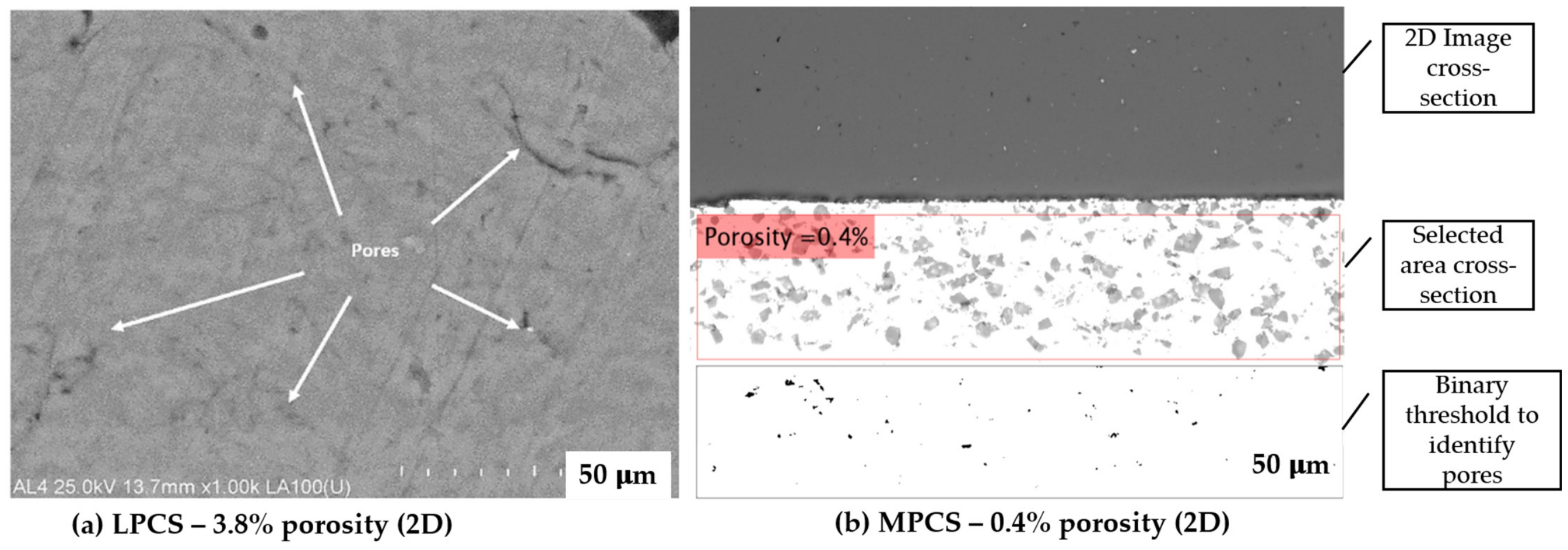
Through finite element modelling of multi-particle impact, Weiller and Delloro [97] distinguished two sources of porosity: interfacial porosity, from gaps at particle–particle contacts where flattening is incomplete, and stack porosity, from variations in local particle number density in the gas stream. The two respond differently to process parameters, the first to impact velocity and the flattening ratio and the second to the powder feed rate and gas flow uniformity. Both are more prominent in LPCS, where impact velocities are constrained and radial downstream injection introduces inhomogeneity, than in high-pressure systems [31].
Spray angle exerts a measurable influence on microstructural quality. Schmidt et al. [98] and Binder et al. [99] both demonstrated that deviation from perpendicular particle impact can increase the porosity population and lower the mechanical properties of the deposit, with the effect becoming significant beyond approximately 45° from the ideal 90° impact angle. This sensitivity is important in field repairs, where restricted access can impose oblique spray angles that depart from the near-normal incidence under which most laboratory characterisation data are obtained.
The porosity values collated in Table 4 were all obtained through two-dimensional cross-sectional image analysis, which tends to underestimate the true porosity content of a cold spray deposit. Koivuluoto et al. [100] found that LPCS deposits of Cu, Ni, and Zn alloys that appeared dense in 2D SEM cross-sections nevertheless contained interconnected porosity, revealed by electrochemical corrosion testing, as a 2D section only samples pores intersecting the cut plane. Porosity acceptance criteria derived from 2D measurements are therefore non-conservative, a technical barrier to qualifying primary load-bearing structures; the values in Table 4 should be read as lower bounds.
Table 4.
Porosity measurements for LPCS-MPCS deposits under various process conditions. All values were obtained through two-dimensional cross-sectional image analysis and should be read as lower bounds on true volumetric porosity.
X-ray computed microtomography (XCT) resolves the deposit volume in three dimensions. Figure 11 shows an AA7075 powder repair of an AA7075-T6 wrought plate sprayed at 6 MPa, with a porosity volume fraction of 0.18% concentrated near the specimen’s surface. Porosity is attributed to incomplete interparticle bonding, insufficient particle deformation, or oxidation during powder atomisation [29]. The pores were irregular in shape, consistent with formation between incompletely bonded particles, and the largest measured about 0.6 mm across. High-resolution XCT is slow, costly, and limited by facility access, so electrochemical corrosion testing has been used as a complementary probe of through-thickness porosity.
Figure 11.
X-ray computed tomography (XCT) images: (a) schematic of the specimen; only the section within the dashed lines was scanned through XCT; (b) image showing porosity defects; volume fraction 0.18%; the colour index shows pore diameter ranges of 0–0.6 mm; (c) an enlarged view to show pores with diameters > 0.2 mm; (d) a higher-magnification image of irregularly shaped pores with a scale bar (0.1 mm) to indicate pore size. Reproduced from [29], copyright 2025 Elsevier.
Shorinov et al. [35] demonstrated that gas temperature is a non-monotonic process variable: an increase in gas temperature to 600 °C produced a slight increase in porosity in deposits produced by a Dymet 413 LPCS system, as illustrated in Figure 12, attributed to pre-impact thermal softening reducing the kinetic energy available for interfacial plastic deformation and incipient nozzle clogging by partially softened particles disrupting the stable supersonic jet. An optimum gas temperature in the range of 450–550 °C or incorporation of Al2O3 particles suppressed inter-particle porosity through enhanced mechanical peening.
Figure 12.
Porosity area fraction as a function of gas temperature for LPCS deposits produced from different aluminium-based powder mixtures illustrating the non-monotonic relationship and the optimum temperature window. Replotted from [35], copyright 2023 IOPScience.
Porosity reduction through ceramic addition is well-documented. Jiang et al. [103] reported a reduction in areal porosity fraction from 6.34% to 2.07% with Al2O3 addition in Al/Al2O3 composite deposits, which is consistent with the broader composite feedstock literature. Piwowarczyk et al. [104] demonstrated that porosity spatial distribution is as important as volume fraction and that pores adjacent to the interface or brittle ceramic stringers can dominate fatigue crack initiation behaviour even when the bulk volume fraction of porosity is low, an observation directly relevant to repair qualification.
5.2. Effect of Ceramic Particle Size on Deposit Microstructure
Although an optimum ceramic content of approximately 20–40 wt% is generally reported for achieving a balance between DE and mechanical performance, ceramic particle size independently governs the mechanisms controlling deposit formation and the resulting microstructure [51,52,84]. Whereas ceramic content determines the amount of reinforcement introduced into the deposit, particle size dictates how the hard phase interacts with the metallic matrix on impact and therefore governs deposit build-up, defect formation, and structural integrity.
Sova et al. [105] showed that ceramic particle size controls competition between surface activation and erosion. Fine Al2O3 (~19 μm) and SiC (~25 μm) particles repeatedly strike the growing deposit, removing surface oxides, generating fresh asperities, and peening the surface, raising the DE of the metallic component above that of pure metal powders and lowering the critical gas temperature by some 60–100 K. Coarse Al2O3 (~141 μm) instead eroded the deposit across the whole processing window. Because erosive potential scales with particle volume while surface activation depends on surface interaction, the detrimental effect rises rapidly with diameter, defining an upper size limit beyond which ceramic reinforcement is counterproductive.
Ceramic particle size also exerts a direct influence on deposit microstructure because ceramic particles cannot deform plastically during impact. Instead, sufficiently large particles tend to shatter, producing smaller angular fragments that become embedded within the metallic matrix and act as preferential sites for microporosity and microcrack initiation. Chupong et al. [106] observed fractured Al2O3 particles distributed throughout LPCS Al–Al2O3 deposits, whereas the incorporation of ultrafine TiN (~1 μm) filled interparticle crevices reduced porosity and suppressed crack formation (Figure 13), demonstrating that finer hard particles improve particle packing and interparticle cohesion. Similarly, Feng et al. [72] reported that decreasing both metallic and Al2O3 particle sizes increased particle deformation, reduced porosity, and produced coatings with superior mechanical properties, with optimum performance obtained using particle sizes of approximately 23–25 μm.
Figure 13.
SEM (backscattered electron micrographs) of deposits showing shattered ceramics dispersed in (a) Al–Al2O3 and (b) Al–Al2O3/TiN deposits. Reproduced from [106], copyright 2025 MDPI.
None of this is represented in the critical velocity models of Section 3.1, which treat particle diameter as a single characteristic of a homogeneous material and so describe only the metallic phase, neglecting the independently sized, non-deforming reinforcement. Models incorporating ceramic particle size, and consistent reporting of ceramic size distributions, remain research needs; ceramic particle size should meanwhile be treated as a primary process variable for composite feedstocks.
5.3. Interface Morphology and Bonding Integrity
Bond quality in LPCS repairs is determined at two distinct boundaries: the interparticle boundary within the deposit, and the deposit–substrate interface. Both are limited by the extent to which impact-induced plastic strain fractures and disperses the native oxide film at the contact, although the contact conditions differ, as the substrate is prepared, initially unhardened, and generally of different roughness and hardness from the impacting particle. Within the deposit, LPCS particles arriving at 300–600 m/s develop insufficient strain at the contact to disrupt the oxide across the full contact area once the elevated effective yield strength of gas-atomised powder is accounted for (Section 3.1). Bonding is consequently localised to mechanically interlocked asperity contacts rather than distributed as metallurgical continuity across the splat interface [21,95]. Figure 14a shows the resulting boundary structure. Kundu and Stamoulis [107] observed the mechanical consequence: LPCS AA6061 fractured through brittle quasi-cleavage across flat splat facets, whereas HPCS deposits of identical geometry fractured through bonded metal with tear ridges and dimpling, indicating micro void coalescence instead of separation along particle boundaries. The measured elastic modulus was 62 GPa for the LPCS deposit against 64 GPa for HPCS and 69 GPa for the wrought substrate, a deficit consistent with a higher density of unbonded interparticle area. Both deposits were monolithic, so this contrast is attributable to velocity regime alone.
Figure 14.
Fracture surfaces of cold-spray-repaired specimens after tensile testing: (a) LPCS-repaired AA6061 showing flat splat facets in the deposit against a fibrous, ductile substrate; (b) HPCS-repaired AA7075 showing tear ridges and dimpling with a discrete crack at the deposit–substrate boundary. (a) Reproduced from [107] and (b) from [29], copyright 2025 Elsevier.
At the deposit–substrate interface, the same oxide disruption limitation applies, and the interface remains a preferred failure plane even where interparticle cohesion is adequate. Bakir et al. [29] reported a discrete crack along the deposit–substrate boundary in HPCS-repaired AA7075 despite ductile fracture through the deposit (Figure 14b). Raising particle velocity therefore improves interparticle cohesion more readily than it eliminates the interface as a failure plane, which is consistent with the fatigue evidence that cracks initiate at the deposit–substrate interface across materials, geometries, and process regimes (Section 6.4). Initiation resistance is thus governed principally by interface conditions, while resistance to subsequent propagation is governed by the interparticle boundary structure within the deposit. Hard-phase addition acts on both boundaries. At the substrate interface, ceramic impact roughens and cleans the surface and generates asperities, increasing contact area and mechanical anchoring, and Spencer et al. [108] showed that Al2O3 reinforcement of cold-sprayed aluminium shifts the failure site from the deposit–substrate interface to cohesive failure within the deposit, indicating that interfacial adhesion had been raised above deposit cohesive strength. Within the deposit, retained ceramic interrupts metallic contact, and Dayı et al. [44] observed microcracks initiating preferentially at ceramic–matrix boundaries under tensile load. Figure 15 shows an Al–Al2O3 deposit–substrate interface exhibiting both features: embedded alumina particles and particle penetration into the substrate with localised plastic deformation of the matrix are seen, alongside interfacial gaps and retained porosity. Based on the available evidence, drawn from separate studies rather than from a single system in which both boundaries were measured, hard-phase addition improves adhesion at the substrate interface while introducing an additional crack initiation path within the deposit.
Figure 15.
Backscattered electron SEM micrographs of an Al–Al2O3 deposit–substrate interface showing interfacial gaps, embedded Al2O3 particles, particle penetration, connected and isolated pores, and localised plastic deformation. Reproduced from [106], copyright 2025 MDPI.
The implication for repair selection is that the two boundaries respond differently to the measures available to portable systems. Interfacial adhesion can be improved through surface preparation and hard-phase addition, whereas interparticle bond quality remains limited by particle velocity and is degraded at high ceramic content (Section 5.2). LPCS repairs are accordingly better suited to restoration of surface function than recovery of load-bearing capacity in fatigue-critical members.
6. Mechanical Performance of Cold Spray Deposits
Substantiating a durable cold spray deposit requires evidence at two levels, the material and the assembly (Figure 16). At the material level, the deposit must show adequate through-thickness hardness, tensile properties, wear and corrosion resistance, and an elastic modulus compatible with the substrate; at the structural level, the assembly must show adequate adhesion and load transfer, fatigue life retention under service loading, and a residual stress state that does not promote distortion or cracking. The following sections address each in turn for portable LPCS and MPCS, with HPCS retained as a baseline.
Figure 16.
Fishbone (Ishikawa) diagram showing the multi-scale determinants of cold spray repair durability. Material-level attributes and structure-level performance converge in the assessment of durable, high-integrity repair deposits. Developed from information in [59,109,110].
6.1. Adhesion Strength
Adhesion strength testing is the most widely used mechanical screening test for structural repairs. ASTM C633 [111] and the more recent ASM Thermal Spray Society acceptance practice are the standard methods for measuring tensile adhesion and cohesion strength through pull-off testing [112]. The values cannot be used directly in structural design calculations, being influenced by residual stress and the geometry of the deposited part [19]. A further standard, ASTM D4541 [113], provides a portable pull-off test suited to the field, measuring the perpendicular tensile force needed to detach a bonded plug. Maxwell [114] compared seven thermally sprayed and electroplated deposits and found that ASTM C633 returns adhesion strengths 15–35% higher than ASTM D4541 for high-adhesion deposits, a difference attributed to its better load alignment and surface preparation protocol.
A limitation common to both methods is that failure of the bonding adhesive itself may become the limiting failure plane, obscuring the nature of the fracture, that is, whether failure is adhesive (at the deposit–substrate interface) or cohesive (within the deposit bulk). Adhesion test results should therefore be treated as screening indicators of bonding continuity, and qualification must complement them with other mechanical tests, including tensile and fatigue evaluation.
Reported adhesion strengths for LPCS aluminium deposits on aluminium substrates span roughly 15–50 MPa under ASTM C633-type testing (Table 5), with the higher values obtained with nitrogen rather than compressed air and with optimised surface preparation. Bi et al. [102] reported adhesion and mechanical property data for LPCS AA2024 and AA7075 deposits in the context of MIL-STD-3021 qualification for non-primary structure repairs, one of the few datasets framed within a regulatory context. Yandouzi et al. [81] reported 26.9 MPa for LPCS commercially pure Al on AA2024-T3.
Excessive addition of hard particles, however, raises the proportion of weak metal–ceramic bonds within the deposit and reduces its cohesive strength, shifting failure from the interface to the deposit interior [115].
Table 5.
Reported adhesion strengths for portable low-pressure cold-sprayed deposits highlighting the influence of process gas, feedstock composition, substrate, and surface preparation.
Piwowarczyk et al. [104] reported adhesion strengths exceeding 50 MPa for LPCS repairs of aluminium casting defects using Al, Zn, and Sn powders reinforced with Al2O3 measured through a pull-off test, as shown in Figure 17; their cohesive and adhesive fracture mode distributions confirm that the interfacial bond strength was sufficient to shift failure into the deposit interior for Al deposits.
Figure 17.
Static tensile (pull-off) adhesion test results for cold-sprayed Al, Zn, and Sn deposits on different substrates, where Al1350 and Al5754 denote the substrate alloys: Al1350 is a commercially pure aluminium (≥99.5% Al), and Al5754 is an Al–Mg (3.6 wt% Mg) wrought alloy of higher strength. Reproduced from [104], copyright 2014 Archives of Foundry Engineering.
A practically important finding is that the beneficial effect of hard particle additions on adhesion strength depends on the failure mode transition: once interfacial adhesion strength is sufficiently strong, the failure site shifts into the deposit interior, indicating that cohesive rather than adhesive strength becomes the limiting property for deposit integrity.
6.2. Hardness and Work Hardening Effects
Cold spray deposits typically exhibit increased hardness relative to the feedstock powder owing to severe plastic deformation imposed by particle impact [36]. The mechanism is strain hardening through dislocation multiplication, which raises the flow stress throughout the deformed volume, so hardening is distributed through the deposit’s thickness rather than confined to a near-surface layer. Hardening remains heterogeneous at the particle scale, however, and is most pronounced at splat peripheries where deformation localises. A distinct contribution arises in the substrate, where peening by impacting particles produces a work-hardened near-surface region together with the compressive residual stress discussed in Section 6.3. While work hardening raises static strength, it reduces ductility and fracture toughness relative to wrought material, a trade-off that is unfavourable where resistance to crack propagation is required [107,117]. Homogeneous deposits provide direct evidence of deformation-induced hardening, as no hard phase contributes to strengthening. Eftekhari and Jahed [118] reported 107 ± 3 HV0.1 for cold-sprayed pure copper, approximately twice the hardness of annealed copper, and confirmed the mechanism through electron backscatter diffraction, observing grain refinement and dynamic recrystallisation concentrated near the substrate’s interface where the accumulated strain was greatest. In composite deposits, the deformation and reinforcement contributions are superimposed and cannot be separated by hardness measurement alone.
Within composite systems, matrix chemistry is the stronger determinant of hardness: Dayı et al. [44] reported 239 ± 23 HV0.1 for Ni–Al2O3 on AA7075, appreciably above the Al and Zn matrix composites deposited with the same reinforcement (Table 6), indicating that the matrix alloy rather than the reinforcement sets the attainable hardness level.
Shorinov et al. [35] reported a 32.7% increase in hardness upon adding Al2O3 to aluminium sprayed at 450 °C, which they attributed jointly to ceramic strengthening and enhanced peening of the matrix. Ductile reinforcement achieves comparable gains without introducing a brittle phase, as Li et al. [91] demonstrated for Al–Ta relative to Al–Al2O3, and post-deposition peening offers a further route; Zhang et al. [119] reported approximately 16% higher hardness for shot-peening-assisted cold spray, although the added process complexity limits field adoption.
Table 6.
Summary of microhardness values for portable LPCS metallic and composite deposits. Indentation load and measurement location differ between studies, so values are not directly comparable.
Table 6 compiles reported microhardness for portable LPCS deposits. The values span 100 to 239 HV for the metallic and composite systems but cannot be compared directly across studies because indentation loads range from HV0.01 to HV0.2 and measurement locations vary between deposit surface, cross-section, and interface-adjacent positions. The consequence is visible within the table: the 196.6 HV0.01 recorded for pure aluminium exceeds values reported for aluminium composite deposits measured at higher loads, which reflects the surface location and light indentation rather than a harder material, while the highest entry corresponds to local sintered TiO2 agglomerates rather than bulk deposit response. Hardness is therefore a useful indicator of deformation state and reinforcement effectiveness within a single study, but it cannot support acceptance criteria or cross-system comparison without a standardised measurement protocol.
6.3. Residual Stress
Cold-sprayed aluminium alloys develop compressive residual stress, arising chiefly from the peening effect of successive particle impacts, in contrast to thermal spray and fusion-based processes, which generate tensile stress through solidification quenching. Higher-strength alloys such as titanium can nevertheless develop tensile deposit stress through quenching and thermal mismatch. Three mechanisms set the final stress state: (a) peening stress arising from high-velocity particle impacts that plastically deform the substrate surface; (b) quenching-analogous stresses arising from constrained relaxation of the rapidly deformed splat; and (c) thermal mismatch stresses resulting from coefficient of thermal expansion (CTE) differences between the deposit and the substrate [123,124,125]. The three contributions superimpose to give the final stress profile. In lower-strength metals such as aluminium, the peening contribution dominates the residual stress state, whereas in higher-strength alloys sprayed at elevated pressures the quenching contribution is significant [124,126].
Neutron diffraction measurements by Luzin et al. [125] confirmed that both copper and aluminium cold spray deposits exhibit compressive residual stress throughout the deposit section regardless of spray parameters, with only the stress magnitude depending on material properties and process energy. Ryabchikov et al. [127] found good agreement between near-surface XRD and incremental hole drilling depth profiles. The stress turns tensile in the substrate to balance the compressive deformation imposed by particle impact, and this tensile field can drive fatigue crack initiation where the substrate or interface contains pre-existing defects.
Modelling studies have provided complementary insights. Boruah et al. [128] showed through a parametric study that the number of deposited layers and the substrate height both influence the magnitude of the through-thickness residual stress, whereas individual layer height has a negligible effect. Manap et al. [88], using smoothed particle hydrodynamics to simulate Al particle impacts on Al, Mg, and Ti substrates under LPCS and HPCS, suggested that LPCS produces lower residual stresses on aluminium substrates and minimises deformation, findings that still require systematic experimental validation before generalisation.
Zhang et al. [67] measured a compressive residual stress of about −48.3 MPa in AA2024–Al2O3 composite deposits on AA2024-T3 containing 20 wt% Al2O3, the composition giving the best balance of hardness, adhesion, and corrosion resistance. Luzin et al. [129] used neutron diffraction to evaluate through-thickness residual stress in Al–Al2O3 and Al–Zn–Al2O3 composite LPCS deposits (Figure 18). The profiles combine mechanical peening and thermal–elastic contributions, with a compressive peak at the deposit midpoint falling to near-zero or slightly tensile at the free surface.
Figure 18.
Residual stress profiles for Al and Al–Zn LPCS deposits calculated for a 4 mm deposit thickness. The zero point on the x-axis is the deposit–substrate interface. Thicker lines show the combined deposition and thermal contributions. Adapted from [129].
Zhang et al. [84] reported compressive residual stresses in the range of −32.1 to −58.0 MPa for different Al alloy deposit compositions, as shown in Figure 19. The variation in stress magnitude was attributed to alloy resistance to plastic deformation rather than differences in the process conditions.
Figure 19.
XRD residual stress measurements at the surface of LPCS deposits for commercially pure Al and different Al alloy compositions showing compressive stresses in the range of −32 to −58 MPa. Replotted from [84].
Reed et al. [130] measured residual stress in cold-sprayed AA7075 repairs through three techniques (Figure 20). Pulstec μ360 XRD gave a uniform compressive surface stress of about 30 MPa in both the x- and y-directions. Incremental hole drilling showed this stress to be non-uniform through depth, peaking 0.24 mm below the surface, the subsurface maximum reflecting plastic deformation by particle impact with slight near-surface relaxation, then decaying to an average of 7 MPa at 1.02 mm. The contour method, evaluated at three positions along the plate, agreed closely: compressive at the surface (14 MPa average), rising to a maximum at 0.27 mm, and turning tensile at an average depth of 1.47 mm where the substrate balances the deposit. The distribution is typical of aluminium cold spray and is governed by the peening mechanism described in [124]. The portable Pulstec μ360 XRD used in [130] is in principle suitable for on-site measurement of field repairs, although such measurements are rarely reported.
Figure 20.
Residual stress in a cold-sprayed AA7075 repair measured through three different techniques: (a) XRD contour plot on CS top surface showing the x direction stress (the y direction stress is the same), (b) through the depth stress distribution in CS coating up to 1 mm, both the x and y directions, obtained using incremental hole drilling method, and (c) through the depth distribution in CS and substrate assembly, obtained using the contour method. Reproduced from [130], copyright 2025 Elsevier.
6.4. Fatigue and Tensile Strength Behaviour
Fatigue damage accounts for a large proportion of in-service failures, so whether a repair can sustain a comparable cyclic regime determines its structural integrity. It is also the least studied aspect of portable LPCS and MPCS repair. One limitation must be stated at the outset: most fatigue data for cold-spray-repaired components come from HPCS, which operates at a substantially higher velocity ratio than field-deployed LPCS [32,33]. Whether crack initiation behaviour, fatigue endurance limit, and interface failure mechanisms from HPCS studies can be transferred to portable LPCS deposits, where bond continuity is less consistently achieved, remains open. This unresolved question in the literature is flagged wherever HPCS data are cited. Several studies have found fatigue cracks in cold-spray-repaired specimens initiated from the deposit–substrate interface, mainly from small craters on the substrate produced by particle impact, as shown in Figure 21 [29,131,132,133]. This reframes the deposit integrity problem: bulk deposit properties are necessary but not sufficient for the durability of a repaired part.
Figure 21.
SEM images of fracture surfaces of repaired AA7075 specimen showing arrows pointing to craters (yellow dash line) or crack initiation and interface for groove repaired (a,b) and dent repaired (c,d). Reproduced from [29], copyright 2025 Elsevier.
Yandouzi et al. [81] reported fatigue performance of repaired specimens comparable with that of the substrate for commercially pure aluminium deposited on Alclad 2024-T3 under strain-controlled testing (strain ratio R = −1, test frequency 20 Hz). The strain life data (Figure 22) scatter widely, with the fitted curve being an upper bound indicating a fatigue limit corresponding to a strain range of approximately 1.82 × 10⁻³. As one of very few portable LPCS fatigue datasets in the open literature, it indicates that geometry-appropriate LPCS can preserve substrate-level fatigue performance consistent with the compressive residual stress field offsetting the stress concentration at the repair boundary.
Figure 22.
Strain life diagram for LPCS-repaired commercially pure Al on Alclad 2024-T3 evaluated under strain-controlled cycling (R = −1, 20 Hz) according to ASTM E739-91. Open circles are failed specimens; arrows denote run-outs. The dashed line shows the fitted fatigue curve. Replotted from [81].
Peng et al. [134] reported in their Phase I durability study that post-deposition annealing substantially reduced fatigue life relative to unannealed repairs, attributed to residual stress relaxation removing the beneficial effect of compressive residual stress. Bakir et al. [29] showed that groove-type repairs to AA7075 can match the fatigue strength of undamaged material at the maximum stress of 200–250 MPa (R = 0.1), provided repair geometry is well-controlled and post-deposition annealing avoided. Both results used HPCS, and their transfer to portable LPCS has not been established directly.
White et al. [135] found that for AA2024-T351 blend-out repairs of fastener hole damage, fatigue life exceeded that of undamaged specimens for repairs placed both inside and outside of the lap-shear configuration, confirming the benefit of the compressive residual stress introduced during material restoration by cold spray. Cavaliere and Silvello [133] found through finite element modelling and experiments that cold spray repair of V-notch damage in AA2099 panels markedly reduced the stress intensity factor, raising crack resistance more than sevenfold, and shifted the maximum stress concentration from the original crack tip to the repaired panel surface, demonstrating that repair geometry can govern the crack initiation site.
The fatigue failure mechanism in cold-spray-repaired specimens is summarised in Figure 23. Two independent studies by Peng et al. [136] and Bakir et al. [29] showed the initiation of fatigue cracks from the aluminium substrate and their subsequent propagation into the substrate. The crack propagation phase in both studies can be seen by the distinct “beach marks” in the substrates. In both studies, the cold spray deposits did not crack until late in the specimen’s life.
Figure 23.
Fatigue fracture surfaces showing crack initiation from small craters or dents caused by particle impact during cold spray process: (a) specimen dimension, (b) crack initiation at the substrate interface with lower repair patch, (c) crack initiation from the substrate with upper repair patch, and (d) SEM image of lead crack. Reproduced from [136], copyright 2021 MDPI.
Bakir et al. [29] identified that crack initiation was from very small “craters” on the substrate interfacing with the deposit (Figure 21). These craters were created by particle impacts at supersonic speed during deposition.
Tensile data for repaired assemblies under in-plane loading are also sparse. Dayi et al. [44] examined an LPCS repair of a 1 mm deep groove in an AA7075 substrate using five composite powders (Ni–Al2O3, Al–Zn–Al2O3, Al–Al2O3, Ni–Zn–Al2O3, Zn–Al2O3). Three specimens were tested per repair condition. Mean curves from the paper are replotted in Figure 24. The stress–strain curve of the undamaged AA7075 specimen showed the expected ductile material behaviour with a strain at fracture just over 14%. All five types of repaired specimens showed brittle fracture behaviour with strain at a fracture of 5%, about 65% lower than that of the substrate material. In terms of strength, the repair using the Ni–Zn–Al2O3 powder gave the best result, with a yield stress of 477 MPa and an ultimate tensile strength of 511 MPa, about 13% below the parent material AA7075. Across all five conditions, yield stress was reduced by roughly 10% relative to the parent alloy.
Figure 24.
Engineering stress–strain curves for undamaged and LPCS-repaired AA7075 specimens produced using Ni–Zn–Al2O3, Al–Zn–Al2O3, Zn–Al2O3, Ni–Al2O3, and Al–Al2O3 powders. Each curve represents the mean response of three specimens and shows the influence of repair composition on strength recovery and ductility. Replotted from [44].
Cautious optimism regarding LPCS fatigue performance rests on the compressive residual stress state characteristic of cold spray deposits (Section 6.3), which retards crack initiation and slows stage I propagation through a substrate-governed rather than system-governed mechanism. Provided the interface achieves sufficient metallurgical continuity, an LPCS repair should follow the same fatigue framework as an HPCS repair, differing in magnitude rather than the underlying deformation physics. Table 7 consolidates the mechanical property data across the three pressure regimes.
Table 7.
Reported mechanical properties for LPCS, MPCS, and HPCS deposits. Entries are drawn from different material systems and test protocols and may not be directly comparable in some cases.
7. Substrate Geometry and Interface Design
7.1. Blend-Out Design and Aspect Ratio Effects
The term “blend-out” describes the preparation of a repair by removing material from the damaged area to create a geometry suited to deposition. Its length ratios, corner radius or taper angle, and transition smoothness control deposition quality and efficiency and the bonding of the deposit–substrate interface [131,134]. The repair patch aspect ratios, namely width-to-depth and repair-thickness-to-substrate-thickness, define the elliptical blend-out geometry commonly adopted in the literature (Figure 25). No agreed framework yet exists for the values of a/t and b/c within which a portable cold spray repair can be expected to deliver durable, damage-tolerant performance, irrespective of whether the originating damage is corrosion thinning, a dent, or surface scoring.
Figure 25.
Geometry of an elliptical blend-out for repairing surface damage by cold spray. The blend-out is defined by an ellipse with major axis 2c and minor axis 2b. Repair depth a and substrate thickness t define the severity ratio a/t and the aspect ratio of the repair patch b/c.
Evidence from wing skin durability studies and fastener hole repair experiments indicates that blend-out depths of 15–30% of plate thickness, combined with smooth taper transitions, can restore fatigue life to near-undamaged levels [135]. Optimal blend-out geometry depends on the applied stress field, the elastic modulus of the repair material relative to the substrate, and the residual stress profile at the interface. Parameters may vary between LPCS and MPCS deposits even for identical material systems.
Blend-out depths reported across cold spray repair studies range from 15% to 50% of substrate thickness, as summarised in Table 8. Figure 26 shows representative repair geometries presented in the literature.
Table 8.
Summary of cold spray repair studies that provided repair geometry and blend-out design. Blend-out ratio is repair patch depth to substrate thickness (a/t). Studies differ in blend-out profile, loading configuration, and specimen geometry. The a/t ratio is reported as a common descriptor and does not capture profile curvature.
Figure 26.
Geometries of repair specimens: (a) cylindrical samples and their coordinate system, Reproduced from [138] copyright 2025 Elsevier; (b) groove or dent repairs under axial tension, Reproduced from [29], copyright 2025 Elsevier.
7.2. Spray Angle Constraints and Their Effect on Interface Quality
Spray angle has the most direct and quantifiable effect on interfacial porosity distribution within a repair geometry. Petráčková et al. [55] showed that trapezoidal (Kt = 3) and conical (Kt = 2) cavities, which impose oblique spray angles on the sidewalls (Figure 27), produced localised porosity of 43% and 12%, respectively, in the highest-stress interfacial regions, precisely where adhesion failure and fatigue crack initiation are most likely, whereas a spherical cavity holding near-normal incidence throughout reduced porosity to a uniform 1%. The prepared cavity profile is therefore not merely a geometric variable but a determinant of interfacial quality, and uniform deposit integrity cannot be assumed across non-planar repairs.
Figure 27.
Schematic cross-sections of trapezoidal, conical, and circular cavity geometries prepared for cold spray repair. Sidewall inclination governs the local spray angle achievable during deposition, with the circular profile maintaining near-normal incidence across the cavity’s surface while the trapezoidal and conical profiles impose increasingly oblique impact on the sidewalls. Adapted from [55].
The depth, sidewall inclination, and transition radius of the damage profile directly determine the spray angles achievable during deposition. On open flat repairs, the nozzle can be held at or near 90° (Figure 28); in recessed grooves, holes, and complex curvature features, it must approach obliquely over at least part of the surface, with the deviation growing as the damage becomes deeper or narrower.
Figure 28.
Substrate tilt configuration for the spray angle study; substrates inclined at 15° and 35° relative to the base plane at constant stand-off distance. Adapted [139].
Blochet et al. [139] investigated the effect of spray angle on aluminium deposition onto AA2024-T3, both experimentally and through finite element analysis, using the tilt configuration in Figure 28. Pure Al particles (11–52 μm, nitrogen-atomised) were sprayed between 30° and 90° with a KINETICS 3000-M system at 3 MPa and 300 °C. Two findings bear directly on portable repair design: below a material- and roughness-dependent critical angle θc (Figure 29a,b), all particles rebounded, giving zero deposition efficiency; bond strength, measured through a laser shock adhesion test (LASAT), degraded substantially and continuously between 60° and 30°. The relationship between prepared surface profile and achievable nozzle angle is therefore critical for manual on-site spraying, where an operator cannot hold near-normal incidence across the whole repair.
Figure 29.
Schematic illustration of powder sprayed onto a substrate tilted at different angles from 90 to 30 relative to a fixed traversing nozzle: (a) top view; (b) cross-section view adapted from [139].
Spraying above 70° was identified as the threshold for obtaining dense deposits with adequate bond strength in their work (3 MPa, 300 °C); applying this threshold directly to LPCS, where particle velocities are substantially lower, requires caution and has not been independently validated. The authors concluded that near-perpendicular incidence is the only reliable condition for high-integrity deposition.
Li et al. [140] showed that oblique impact generates a tangential velocity component at the contact zone that is absent at normal incidence. As the spray angle falls below 90°, this component grows relative to the normal one, driving the deforming particle laterally across the substrate instead of into it, reducing the splat–substrate contact area and mechanical anchoring and leaving a trailing-edge gap that interrupts oxide disruption and metallurgical bonding. Binder et al. [99] confirmed experimentally that deviation from perpendicular incidence increases deposit porosity and degrades mechanical properties, with degradation becoming significant beyond approximately 45° deviation from normal incidence for titanium deposits, a finding consistent with the aluminium results [139].
These findings place a quantitative constraint on acceptable blend-out geometries for portable repair. Sidewalls imposing spray angles below about 60° on any part of the repair area present a deposit quality problem that process parameter optimisation alone cannot correct. The practical responses are to machine a shallower taper before repair, use a multi-pass robotic strategy that rotates the nozzle to keep near-perpendicular incidence at each surface element, or accept inferior sidewall bond integrity and substantiate the structure accordingly.
Yin et al. [141] also noted that substrate temperature rises non-uniformly under oblique spraying due to the asymmetric heat input distribution, which introduces additional variability in particle deformation behaviour across the repair surface area. In combination, these effects mean that substrate sidewall geometry is a primary deposit process design variable, not merely a manufacturing consideration.
7.3. Process Regime Selection as a Deposit Integrity Decision
Process selection should follow from the specific repair geometry. For shallow, broad damage where the depth-to-thickness ratio is small and the substrate retains an adequate residual section, LPCS is sufficient provided bond continuity can be verified and the blend-out minimises stress concentration [131]. Where damage is deep or volumetric and the deposit carries more of the applied load and the geometry is inherently notch-sensitive, the higher impact velocity of MPCS should reduce incomplete interparticle bonding. In the absence of experimental data, the magnitude of this advantage can be bounded using the gas dynamic model of Section 3.1.
In the analytical solution of Martínez-Flores et al.’s [32] Equation (7), particle velocity follows , approaching a ceiling of at a rate set by the acceleration coefficient . The two parameters respond differently to the process inputs. Because β scales with gas density and is proportional to at constant stagnation temperature, raising stagnation pressure from below 1 MPa to the 1–3 MPa MPCS range increases β approximately in proportion, so a greater fraction of is attained within the same nozzle length. The ceiling itself is unaffected by pressure, being set by gas velocity alone. Raising stagnation temperature acts on the other parameter, , so increasing from 600 to 800 °C raises by approximately 11% while simultaneously reducing gas density and hence β by approximately 10%, as β is proportional to p0/√T0. Pressure and temperature therefore act on different terms and partially oppose one another, so the net gain depends on the pressure–temperature combination selected and is not set by pressure alone.
Equation (6) can be evaluated for commercially pure aluminium. Equation (2) gives a critical velocity of approximately 620 m/s for a moderately preheated particle derived from bulk material properties. Wiehler et al. [43] measured an effective yield strength for gas-atomised aluminium approximately 81% above the bulk value, which enters the strength term of Equation (3) and places the critical velocity above 620 m/s. The LPCS particle velocity range of 300–600 m/s therefore corresponds to η at or below unity for a homogeneous metallic feedstock. This is the basis of the dependence of LPCS on composite feedstocks, in which ceramic addition supplies surface activation and densification that velocity alone does not achieve (section effect of ceramic particle size on deposit microstructure). At the upper MPCS particle velocity of 800 m/s quoted by equipment manufacturers [16], the velocity ratio η exceeds unity by a small margin. MPCS therefore operates within the stable deposition regime for pure aluminium, though still below the η ~ 1.5 optimum identified in Section 3.1. For Ti-6Al-4V and Ni-base feedstocks, whose critical velocities are higher, the margin becomes smaller.
Precipitation-hardened alloys reduce the margin further. In Equation (3), the strength term dominates: the flow stress of the 2xxx and 7xxx alloys exceeds that of annealed pure aluminium by roughly an order of magnitude, while the thermal term acts in the opposite direction, as the solidus of these alloys lies below the melting point of pure aluminium and reduces . The net effect is a substantially higher critical velocity. Portable systems nevertheless deposit these alloys, as reported for AA2024 and AA7075 [67,84,102], through three compensating measures: ceramic addition, elevated gas temperature, which raises the particle impact temperature Ti and further reduces (Tm − Ti), and nitrogen propellant in place of air. Table 3 shows that pure Al and Al composite feedstocks predominate, which reflects the extent of compensation required.
Table 8 records the repair geometries used in the blend-out studies. Lang et al. [138] deposited into a cavity on an Inconel 718 cylindrical shaft and found that curvature introduces spray angle and stand-off variability, degrading interface continuity relative to flat coupon testing. Component curvature is therefore a variable influencing the effective process window, alongside blend-out slope and depth.
8. Deposit Qualification and Process Validation Framework
8.1. Regulatory Standards
The standard framework for cold spray repair has been developed largely within the US military. MIL-STD-3021, issued by the US Army Research Laboratory in 2008 and amended in 2015 and 2019, sets process control requirements covering equipment qualification, operator certification, parameter documentation, and inspection [142]. Appendix A, Table A.1 of MIL-STD-3021 covers structural and safety-critical applications and requires a qualification plan approved by the Cognizant Engineering Authority and proof testing appropriate to the intended loading. It does not specify mechanical performance acceptance criteria for individual repairs; that responsibility rests with the engineering authority overseeing each qualified process.
SAE Aerospace Material Specification AMS 7057, co-developed with the SAE International Additive Manufacturing Committee and published in 2024, represents the first cold spray process specification developed under commercial consensus standard processes [143]. Covering both additive manufacturing and repair, it signals a shift from purely military qualification to civil aerospace engagement. Neither the Federal Aviation Administration (FAA) nor the European Union Aviation Safety Agency (EASA) has yet published cold-spray-specific guidance, leaving civil primary structure in a regulatory gap resembling that of metal additive manufacturing a decade ago.
USAF Structures Bulletin EZ-SB-19-01 provides engineering guidance for cold spray substantiation within a damage tolerance assessment framework [144], addressing the requirement to demonstrate that the repaired structure meets the same crack growth and residual strength requirements as the original design. This bulletin is operationally the most relevant qualification guidance for structural cold spray repairs to USAF aircraft, and its principles may be applicable to LPCS and MPCS repairs when the repair process can be shown to produce interface integrity consistent with the accepted damage tolerance model.
8.2. Operational Deployment Records
The deployment record, which covers LPCS and HPCS rather than MPCS, gives indirect evidence of readiness at the system level and of the scale of remaining certification work (Table 9). Corpus Christi Army Depot has restored UH-60 Black Hawk magnesium gearbox housings through cold spray since about 2012, with documented savings across the US Department of Defence (DoD) repair portfolio [109]. The US Navy has approved repair processes at Fleet Readiness Center Southwest encompassing multiple aircraft components, with on-aircraft structural repair of V-22 Osprey windowsill structure demonstrated [145]. The United States Air Force (USAF) 7th Equipment Maintenance Squadron has deployed portable cold spray capability for aircraft outer-panel repairs [9]. These deployments confirm that portable cold spray is operationally mature at the system level, but almost all approved applications are classified as non-primary structures under existing regulatory frameworks; deposit integrity and qualification for load-bearing, safety-critical structures remain open research questions.
Table 9.
Examples of field-deployable portable and mobile cold spray repair applications in aerospace, defence, and other industries. Entries drawn from manufacturer and operator reports have not been independently peer reviewed.
9. Comparative Assessment and System Selection
Selection of a portable cold spray regime for a surface engineering or repair application requires an integrated assessment of trade-offs across process performance, logistics, and substrate geometry. Table 10 compares LPCS, MPCS, and HPCS at the level of individual capability attributes. The figures given are representative of commonly reported values for commercial systems and are indicative rather than prescriptive.
Table 10.
Comparative assessment of LPCS, MPCS, and HPCS for surface engineering and repair applications. Values are indicative of commercially available systems and are not controlled comparisons.
The velocity ratio quantifies the margin available to absorb spray angle deviation, stand-off drift, and oxide state variation in the field. LPCS operates closest to the critical velocity threshold, so any parameter perturbation disproportionately reduces bonding reliability. The accompanying deposition efficiency gap compounds this into structural risk through the multi-pass build-up consequences described in Section 4.2.
Field deployability reverses this ranking. LPCS is operable by a single technician on shop-compressed air, MPCS units can weigh some four times more because of their generator requirement, and current HPCS designs are not field-deployable at all. For forward-deployed repair, LPCS is therefore the only viable option, and the selection question is reduced to whether the intended repair falls within its qualification boundary.
10. Conclusions and Future Outlook
This review has established that portable low-pressure and medium-pressure cold spray must be treated as a distinct class of deposition system in terms of process physics and not as a portable variant of high-pressure cold spray. The conclusions below are drawn from the open literature, and the priorities that follow from them are set out in Section 10.2.
10.1. Conclusions
- Portable LPCS and MPCS repairs should be assessed as a distinct class in which process window control, deposit integrity, and repair geometry jointly determine structural suitability.
- LPCS offers clear advantages for field-deployable surface restoration, corrosion protection, and dimensional recovery, but its narrow velocity margin restricts the material set and makes deposit quality highly sensitive to gas temperature, pressure, powder morphology, stand-off distance, and spray angle.
- Bonding in LPCS deposits is predominantly localised at mechanically interlocked asperity contacts and is not distributed as metallurgical continuity, which limits strength and crack growth resistance relative to HPCS.
- MPCS offers a wider material envelope while retaining portability, but peer-reviewed data remain too sparse for robust comparison with LPCS or for confident structural qualification.
- Bulk deposit properties are necessary but not sufficient for repair durability, as fatigue cracks are initiated predominantly at the deposit–substrate interface across materials, geometries, and process regimes.
- Hard particle additions can improve deposition efficiency, densification, hardness, and adhesion, but excessive ceramic content or unsuitable particle size introduces brittle interfaces and fatigue-sensitive defects.
- Compressive residual stress from particle peening is among the strongest arguments for cold spray repair, because it may offset stress concentration at the repair boundary, though post-deposition heat treatment relaxes this benefit.
- Repair geometry is a controlling design variable rather than a preparation detail, with blend-out depth, taper ratio, and local spray angle determining whether adequate velocity ratio and interface continuity are maintained across the repair surface.
- Porosity acceptance criteria based on two-dimensional cross-sectional analysis are non-conservative, as 2D measurement underestimates volumetric porosity.
- The principal barrier to qualification for primary structures is the absence of geometry-sensitive fatigue data for portable systems, with the available evidence drawn predominantly from HPCS and simplified coupon geometries.
10.2. Future Outlook
The conclusions above identify where the evidence base is insufficient. The following priorities address those deficiencies:
- Geometry-sensitive fatigue substantiation: Testing on representative repair geometries should span the range of blend-out depths, taper ratios, and spray angles encountered in field repair, under load spectra relevant to the intended application, so that the interaction between geometry and interface continuity can be quantified.
- Controlled LPCS–MPCS comparison: Direct comparison is needed to establish when the additional pressure and temperature capability of MPCS justify its greater infrastructure requirement. Such a programme should vary process regime alone while holding feedstock, substrate, surface preparation, stand-off distance, spray angle, and repair geometry constant.
- MPCS property datasets: The measurements required, in priority order, are deposition efficiency, porosity, adhesion strength, residual stress, tensile behaviour, fatigue performance, and repair repeatability across commercially relevant alloys.
- Three-dimensional defect characterisation: Standardised X-ray computed microtomography protocols at sufficient spatial resolution are needed to underpin porosity acceptance criteria for load-bearing repairs, alongside field-deployable non-destructive methods, including ultrasonic phased-array inspection, for in-service assessment.
- Combined fatigue and environmental durability: The interaction between corrosion pitting, moisture ingress through porous deposits and galvanic effects at dissimilar material interfaces, and fatigue crack growth at the deposit–substrate interface, has not been investigated for portable repair geometries under service-representative conditions.
- Process window under field environmental conditions: The effects of ambient temperature outside of manufacturer-recommended ranges, relative humidity, salt contamination, and substrate temperature variability on bonding quality and deposit integrity remain uncharacterised, despite their direct relevance to maritime, arctic, and tropical deployment.
- Standardised reporting: Powder morphology, ceramic content and particle size, substrate roughness and oxide state, porosity measurement method, residual stress depth profile, and failure location should be reported as standard. The absence of these parameters obstructs synthesis of existing results and the generation of open, comparable datasets across multiple portable systems and repair geometries. This is a prerequisite for both structural qualification and the predictive process models that would depend on them.
Author Contributions
K.O.A., writing—original draft preparation, conceptualisation, methodology, analysis, data synthesis. D.B., writing—review and editing, methodology, supervision, conceptualisation. X.Z., writing—review and editing, methodology, supervision, conceptualisation. M.E.F., writing—review and editing, funding acquisition, supervision. D.K., writing—review and editing, supervision. D.R., writing—review and editing, supervision. All authors have read and agreed to the published version of the manuscript.
Funding
This research was funded by the Lloyd’s Register Foundation through TWI Ltd. and supported by Coventry University. The industrial supervisor from TWI Ltd. was involved in the study design, collection, analysis, interpretation of data, the writing of the article and the decision to submit for publication.
Data Availability Statement
No new data were created or analysed in this study. Data sharing is not applicable to this article.
Acknowledgments
This work forms part of an industry-driven PhD project led by the National Structural Integrity Research Centre (NSIRC) at TWI Ltd. and funded by the Lloyd’s Register Foundation. Lloyd’s Register Foundation is a charitable foundation helping to protect life and property by supporting engineering-related education, public engagement, and the application of research. The research was undertaken at NSIRC, a postgraduate engineering facility established and managed by TWI Ltd. KOA thanks Coventry University for their contribution toward the PhD studentship. The industrial supervisor from TWI Ltd. was involved in the study design, collection, analysis, interpretation of data, the writing of the article and the decision to submit for publication.
Conflicts of Interest
Author Dibakor Boruah was employed by the company TWI Ltd. with the Metallic Materials and Integrity section. The other authors declare no known competing commercial interests or personal relationships that could have appeared to influence the work reported in this paper.
Abbreviations
The following abbreviations are used in this manuscript:
| AIN | Aluminium Nitride |
| ASI | Adiabatic Shear Instability |
| ASTM | American Society for Testing and Materials |
| CP-Al | Commercially Pure Aluminium |
| CTE | Coefficient of Thermal Expansion |
| DE | Deposition Efficiency |
| DoD | Department of Defence |
| E-Cu | Electrolytic (dendritic) Copper |
| EASA | European Union Aviation Safety Agency |
| EZ-SB-19-01 | USAF Engineering Structures Bulletin 19-01 |
| FAA | Federal Aviation Administration |
| HAZ | Heat-Affected Zone |
| HPCS | High-Pressure Cold Spray |
| HV | Vickers Hardness |
| LASAT | Laser Shock Adhesion Test |
| LPCS | Low-Pressure Cold Spray |
| MPCS | Medium-Pressure Cold Spray |
| S-Cu | Spherical Gas-Atomised Copper |
| SAE | Society of Automotive Engineers |
| SEM | Scanning Electron Microscopy |
| SoD | Stand-off Distance |
| USAF | United States Air Force |
| XCT | X-ray Computed Microtomography |
| XRD | X-Ray Diffraction |
References
- Ross, K.; Jiang, X.; Alabi, M.; Enderlin, C. Investigation of Cold Spray as a Dry Storage Canister Repair and Mitigation Tool; US Department of Energy: Richland, WA, USA, 2020. [CrossRef] [Scilit]
- Baker, A.; Rose, L.; Jones, R. Advances in the Bonded Composite Repair of Metallic Aircraft Structure; Elsevier: Amsterdam, The Netherlands, 2002; pp. 1051–1061. [Google Scholar] [CrossRef] [Scilit]
- European Aluminium Association. Characteristics of Aluminium in Fusion Welding, EAA Aluminium Automotive Manual—Joining. 2022, pp. 1–21. Available online: https://european-aluminium.eu/wp-content/uploads/2022/11/2-aluminium-fusion-welding_2015.pdf (accessed on 2 March 2026).
- El-Batahgy, A.-M.; Klimova-Korsmik, O.; Akhmetov, A.; Turichin, G. High-Power Fiber Laser Welding of High-Strength AA7075-T6 Aluminum Alloy Welds for Mechanical Properties Research. Materials 2021, 14, 7498. [Google Scholar] [CrossRef] [Scilit] [PubMed]
- Federal Aviation Administration (FAA). Advisory Circular AC 43.13-1B—Acceptable Methods, Techniques and Practices—Aircraft Inspection and Repair; FAA: Washington, DC, USA, 1998.
- Alkhimov, A.P.; Papyrin, A.N.; Vyazemskogo, U.; Kosarev, V.F.; Nesterovich, N.I.; Shushpanov, M.M. Gas-Dynamics Spraying Method for Applying Coating. US5302414A, 12 April 1994. [Google Scholar]
- Assadi, H.; Kreye, H.; Gärtner, F.; Klassen, T. Cold spraying—A materials perspective. Acta Mater. 2016, 116, 382–407. [Google Scholar] [CrossRef] [Scilit]
- Villafuerte, J.; Wright, D. Practical cold spray success: Repair of Al and Mg alloy aircraft components. Adv. Mater. Process. 2010, 168, 53–55. [Google Scholar]
- Tran, 7th EMS Multiplies Combat Readiness with Cold Spray Capability, DYESS Air Force Base. 2025. Available online: https://www.dyess.af.mil/News/Article/4218155/7th-ems-multiplies-combat-readiness-with-cold-spray-capability/ (accessed on 2 March 2026).
- Leyman, P.; Champagne, K. Cold Spray Process Development for the Reclamation of the Apache Helicopter Mast Support. 2009. Available online: https://www.researchgate.net/publication/235150983 (accessed on 10 April 2025).
- Champagne, V.K., Jr.; Ozdemir, O.C.; Nardi, A. Practical Cold Spray; Springer: Berlin/Heidelberg, Germany, 2021. [Google Scholar] [CrossRef] [Scilit]
- Plasma. PCS-1000 & 100 Gun, High Pressure and High Gas Temperature Cold Spray System. Available online: http://plasma.co.jp/en/service/cold/pcs_gun/ (accessed on 16 March 2026).
- DYMET. Profesional Manual and CNC Operating Cold Gas Dynamic Spray DYMET423. Available online: https://dymet.ee/products-2/products/ (accessed on 31 May 2025).
- Kashirin, A.; Klyuev, O.; Buzdygar, T.; Shkodhkin, A. DYMET Technology Evolution and Application, Obninsk, Russia. Available online: https://dymet.net/ext_images/File/DYMET_Evolution_Application.pdf (accessed on 3 April 2025).
- Shiddieqy, R.H.A.; Wikarta, A.; Pramono, A.S.; Suwarno, Y.; Tsai, J.-T. Addressing challenges in deposition efficiency and material compatibility in low-pressure cold spray systems. Results Eng. 2025, 26, 105065. [Google Scholar] [CrossRef] [Scilit]
- Titomic. Titomic, D623 Medium-Pressure Cold Spray System. Available online: https://titomic.com/systems/d623-standard-custom/ (accessed on 3 April 2025).
- Stamoulis, K.; Abouhamzeh, M.; Koufis, S.; Bosma, B.; Anderiessen, L.; Pascoe, J.-A. Developing a Qualification and Testing Framework for Cold Spray Repairs in Aerospace Applications. Eng. Proc. 2026, 133, 178. [Google Scholar] [CrossRef] [Scilit]
- Tregenza, O.; Hutasoit, N.; Palanisamy, S.; Hulston, C. Air-based cold spray: An advanced additive manufacturing technique for functional and structural applications. Int. J. Adv. Manuf. Technol. 2025, 136, 4677–4714. [Google Scholar] [CrossRef] [Scilit]
- Adaan-Nyiak, M.A.; Tiamiyu, A.A. Recent advances on bonding mechanisms in cold spray process: A review of single-particle impact methods. J. Mater. Res. 2023, 38, 69–95. [Google Scholar] [CrossRef] [Scilit] [PubMed]
- Assadi, H.; Gärtner, F.; Stoltenhoff, T.; Kreye, H. Bonding mechanism in cold gas spraying. Acta Mater. 2003, 51, 4379–4394. [Google Scholar] [CrossRef] [Scilit]
- Hassani-Gangaraj, M.; Veysset, D.; Champagne, V.K.; Nelson, K.A.; Schuh, C.A. Adiabatic shear instability is not necessary for adhesion in cold spray. Acta Mater. 2018, 158, 430–439. [Google Scholar] [CrossRef] [Scilit]
- Assadi, H.; Gärtner, F.; Klassen, T.; Kreye, H. Comment on ‘Adiabatic shear instability is not necessary for adhesion in cold spray’. Scr. Mater. 2019, 162, 512–514. [Google Scholar] [CrossRef] [Scilit]
- Hassani-Gangaraj, M.; Veysset, D.; Champagne, V.K.; Nelson, K.A.; Schuh, C.A. Response to Comment on “Adiabatic shear instability is not necessary for adhesion in cold spray”. Scr. Mater. 2019, 162, 515–519. [Google Scholar] [CrossRef] [Scilit]
- Eden, T.J.; Ozdemir, O.C.; Champagne, V.K. Process Description. In Practical Cold Spray; Springer International Publishing: Cham, Switzerland, 2021; pp. 27–51. [Google Scholar] [CrossRef] [Scilit]
- Titomic Limited, Airbus Selects Titomic as Supplier of Cold Spray Equipment for Aerospace Applications. 2023. Available online: https://titomic.com/airbus-titomic-mro/ (accessed on 29 May 2025).
- Centerline, CenterLine SST, Introducing PX & EPX Cold Spray Systems, CenterLine (Windsor) Ltd., Centerline. Available online: https://www.supersonicspray.com/ (accessed on 29 November 2025).
- Nardi, A.; Helfritch, D.; Eden, T.; Ozdemir, O.C. Cold Spray Economics. In Practical Cold Spray; Springer International Publishing: Cham, Switzerland, 2021; pp. 285–310. [Google Scholar] [CrossRef] [Scilit]
- Widener, C.A.; Carter, M.J.; Ozdemir, O.C.; Hrabe, R.H.; Hoiland, B.; Stamey, T.E.; Champagne, V.K.; Eden, T.J. Application of High-Pressure Cold Spray for an Internal Bore Repair of a Navy Valve Actuator. J. Therm. Spray Technol. 2016, 25, 193–201. [Google Scholar] [CrossRef] [Scilit]
- Bakir, A.; Reed, R.; Zhang, X.; Syed, A.; Reed, P.; McNutt, P.; Dore, M. Fatigue performance of cold spray repaired aluminium alloy 7075. Int. J. Fatigue 2025, 198, 109036. [Google Scholar] [CrossRef] [Scilit]
- Strumban, R.; Maev, E. Portable, Low-pressure cold spray systems for industrial application. In The Cold Spray Materials Deposition Process Fundamentals and Applications; Metals and Surface Engineering; Woodhead Publishing: Cambridge, UK, 2007. [Google Scholar]
- Rokni, M.R.; Nutt, S.R.; Widener, C.A.; Champagne, V.K.; Hrabe, R.H. Review of Relationship Between Particle Deformation, Coating Microstructure, and Properties in High-Pressure Cold Spray. J. Therm. Spray Technol. 2017, 26, 1308–1355. [Google Scholar] [CrossRef] [Scilit]
- Martínez-Flores, M.; Cervantes-Cabello, J.J.; Barba-Pingarrón, A. Low-Pressure Cold Spray Deposition Window Derived from a One-Dimensional Analytical Model. Coatings 2023, 13, 1015. [Google Scholar] [CrossRef] [Scilit]
- Assadi, H.; Schmidt, T.; Richter, H.; Kliemann, J.-O.; Binder, K.; Gärtner, F.; Klassen, T.; Kreye, H. On Parameter Selection in Cold Spraying. J. Therm. Spray Technol. 2011, 20, 1161–1176. [Google Scholar] [CrossRef] [Scilit]
- Shorinov, O.; Dolmatov, A.; Polyviany, S.; Balushok, K. Optimisation of cold spray process parameters to maximise adhesion and deposition efficiency of Ni+Al2O3 coatings. Mater. Res. Express 2023, 10, 126401. [Google Scholar] [CrossRef] [Scilit]
- Shorinov, O.; Dolmatov, A.; Polyviany, S. The effect of process temperature and powder composition on microstructure and mechanical characteristics of low-pressure cold-spraying aluminium-based coatings. Mater. Res. Express 2023, 10, 026401. [Google Scholar] [CrossRef] [Scilit]
- Koivuluoto, H.; Lagerbom, J.; Kylmälahti, M.; Vuoristo, P. Microstructure and Mechanical Properties of Low-Pressure Cold-Sprayed (LPCS) Coatings. J. Therm. Spray Technol. 2008, 17, 721–727. [Google Scholar] [CrossRef] [Scilit]
- Smith, S.N.L.M.F. Introduction to Cold Spray. In High Pressure Cold Spray: Principles and Applications; ASM International: Almere, The Netherlands, 2016; pp. 1–16. [Google Scholar] [CrossRef] [Scilit]
- Winnicki, M. Advanced Functional Metal-Ceramic and Ceramic Coatings Deposited by Low-Pressure Cold Spraying: A Review. Coatings 2021, 11, 1044. [Google Scholar] [CrossRef] [Scilit]
- VRC Metals Systems. VRC Raptor High-Pressure Portable System. Available online: https://vrcmetalsystems.com/equipment/vrc-raptor (accessed on 3 April 2025).
- Spee3D, WarpSpee3D, Spee3D. Available online: https://www.spee3d.com/product/warpspee3d/ (accessed on 29 November 2025).
- Ahmed, R.; Ali, O.; Berndt, C.C.; Fardan, A. Sliding Wear of Conventional and Suspension Sprayed Nanocomposite WC-Co Coatings: An Invited Review. J. Therm. Spray Technol. 2021, 30, 800–861. [Google Scholar] [CrossRef] [Scilit]
- Schmidt, T.; Gärtner, F.; Assadi, H.; Kreye, H. Development of a generalised parameter window for cold spray deposition. Acta Mater. 2006, 54, 729–742. [Google Scholar] [CrossRef] [Scilit]
- Wiehler, L.; Capan, J.; Arabgol, Z.; Huang, C.; List, A.; Gärtner, F.; Klassen, T. Calibration of the Critical Velocity Description in Cold Spray. J. Therm. Spray Technol. 2025, 34, 587–596. [Google Scholar] [CrossRef] [Scilit]
- Dayı, S.C.; Kılıçay, K. Repairing Al7075 surface using cold spray technology with different metal/ceramic powders. Surf. Coat. Technol. 2024, 489, 131124. [Google Scholar] [CrossRef] [Scilit]
- Pal, M. Low-pressure cold metal spray coatings for repair and protection of marine components. In Proceedings of the International Naval Engineering Conference and Exhibition (INEC); IMarEST: London, UK, 2018. [Google Scholar] [CrossRef] [Scilit]
- Meng, Y.; Saito, H.; Bernard, C.A.; Ichikawa, Y.; Ogawa, K. Parametric Study to Repair Leaks in Water Pipe Using the Low-Pressure Cold Spray Technique. J. Therm. Spray Technol. 2022, 31, 2560–2576. [Google Scholar] [CrossRef] [Scilit]
- Deforce, B.; Eden, T.; Potter, J. Cold spray Al-5% Mg coatings for the corrosion protection of Magnesium Alloys. J. Therm. Spray Technol. 2011, 20, 1352–1358. [Google Scholar] [CrossRef] [Scilit]
- Centerline. Centerline SST Applicatioin Considerations. Available online: https://www.supersonicspray.com/applications/application-considerations? (accessed on 3 December 2025).
- Kuman Behera, A.; Mantry, S.; Roy, S.; Pati, S. Improving bond strength and deposition efficiency of ceramic coatings via low pressure cold spray. A study of HA coatings with Cu-Zn blends. Surf. Coat. Technol. 2024, 494, 131430. [Google Scholar] [CrossRef] [Scilit]
- Shorinov, O.; Zorik, I.; Nyzhnyk, S.; Savchenko, N.; Danko, K. In-situ strategy towards enhancing cold spray coating deposition efficiency. Mater. Res. Express 2025, 12, 126402. [Google Scholar] [CrossRef] [Scilit]
- Irissou, E.; Legoux, J.-G.; Arsenault, B.; Moreau, C. Investigation of Al-Al2O3 Cold Spray Coating Formation and Properties. J. Therm. Spray Technol. 2007, 16, 661–668. [Google Scholar] [CrossRef] [Scilit]
- Shkodkin, A.; Kashirin, A.; Klyuev, O.; Buzdygar, T. Metal Particle Deposition Stimulation by Surface Abrasive Treatment in Gas Dynamic Spraying. J. Therm. Spray Technol. 2006, 15, 382–386. [Google Scholar] [CrossRef] [Scilit]
- Winnicki, M.; Małachowska, A.; Baszczuk, A.; Rutkowska-Gorczyca, M.; Kukla, D.; Lachowicz, M.; Ambroziak, A. Corrosion protection and electrical conductivity of copper coatings deposited by low-pressure cold spraying. Surf. Coat. Technol. 2017, 318, 90–98. [Google Scholar] [CrossRef] [Scilit]
- Moreno-Murguia, B.; Mora-Garcia, A.G.; Canales-Siller, H.; Giraldo-Betancur, A.L.; Espinosa-Arbelaez, D.G.; Muñoz-Saldaña, J. Influence of stand-off distance and pressure in copper coatings deposition efficiency and particle velocity. Surf. Coat. Technol. 2022, 430, 127986. [Google Scholar] [CrossRef] [Scilit]
- Petráčková, K.; Kondás, J.; Guagliano, M. Fixing a hole (with cold spray). Int. J. Fatigue 2018, 110, 144–152. [Google Scholar] [CrossRef] [Scilit]
- Li, W.; Wu, H.; Verdy, C.; Costil, S.; Liao, H.; Deng, S. Study of Low-Pressure Cold Spray Additive Manufacturing: Investigation of Kinematic Spray Parameters on Deposition and Properties, 3D Print. Addit. Manuf. 2023, 10, 1260–1271. [Google Scholar] [CrossRef] [Scilit] [PubMed]
- Seraj, R.A.; Abdollah-zadeh, A.; Dosta, S.; Canales, H.; Assadi, H.; Cano, I.G. The effect of traverse speed on deposition efficiency of cold sprayed Stellite 21. Surf. Coat. Technol. 2019, 366, 24–34. [Google Scholar] [CrossRef] [Scilit]
- Klinkov, S.V.; Kosarev, V.F.; Shikalov, V.S. Influence of nozzle velocity and powder feed rate on the coating mass and deposition efficiency in cold spraying. Surf. Coat. Technol. 2019, 367, 231–243. [Google Scholar] [CrossRef] [Scilit]
- Galyon Dorman, S.E.; Ausherman, M.J.; Rausch, J.W. Aluminum Cold Spray for Aircraft Structural Repair. In CONFERENCE 2023; AMPP: Houston, TX, USA, 2023; pp. 1–10. [Google Scholar] [CrossRef] [Scilit]
- Boruah, D.; Zhang, X. Effect of Post-Deposition Solution Treatment and Ageing on Improving Interfacial Adhesion Strength of Cold Sprayed Ti6Al4V Coatings. Metals 2021, 11, 2038. [Google Scholar] [CrossRef] [Scilit]
- Marrocco, T.; McCartney, D.G.; Shipway, P.H.; Sturgeon, A.J. Production of titanium deposits by cold-gas dynamic spray: Numerical modelling and experimental characterisation. J. Therm. Spray Technol. 2006, 15, 263–272. [Google Scholar] [CrossRef] [Scilit]
- Ziemian, C.W.; Sharma, M.M.; Bouffard, B.D.; Nissley, T.; Eden, T.J. Effect of substrate surface roughening and cold spray coating on the fatigue life of AA2024 specimens. Mater. Des. 2014, 54, 212–221. [Google Scholar] [CrossRef] [Scilit]
- Champagne, V.; Helfritch, D. The unique abilities of cold spray deposition. Int. Mater. Rev. 2016, 61, 437–455. [Google Scholar] [CrossRef] [Scilit]
- Champagne, V.; Helfritch, D. Critical Assessment 11: Structural repairs by cold spray. Mater. Sci. Technol. 2015, 31, 627–634. [Google Scholar] [CrossRef] [Scilit]
- Li, Z.; Li, Z. EIS and potentiodynamic polarization studies of arc-sprayed aluminum coating on Q235 steel surface. Int. J. Electrochem. Sci. 2023, 18, 100058. [Google Scholar] [CrossRef] [Scilit]
- Winnicki, M.; Baszczuk, A.; Gibas, A.; Jasiorski, M. Experimental study on aluminium bronze coatings fabricated by low pressure cold spraying and subsequent heat treatment. Surf. Coat. Technol. 2023, 456, 129260. [Google Scholar] [CrossRef] [Scilit]
- Zhang, Z.; Liu, F.; Han, E.-H.; Xu, L.; Uzoma, P.C. Effects of Al2O3 on the microstructures and corrosion behaviour of low-pressure cold gas sprayed Al 2024-Al2O3 composite coatings on AA 2024-T3 substrate. Surf. Coat. Technol. 2019, 370, 53–68. [Google Scholar] [CrossRef] [Scilit]
- Feng, L.; Guan, C.; Chang, J.R.; Zhai, H.M.; An, G.S.; Li, W.S. Preparation and performance of a cold gas dynamic sprayed high-aluminum bronze coating. Int. J. Miner. Metall. Mater. 2018, 25, 1354–1361. [Google Scholar] [CrossRef] [Scilit]
- Szala, M.; Łatka, L.; Walczak, M.; Winnicki, M. Comparative study on the cavitation erosion and sliding wear of cold-sprayed Al/Al2O3 and Cu/Al2O3 coatings, and stainless steel, aluminium alloy, copper and brass. Metals 2020, 10, 856. [Google Scholar] [CrossRef] [Scilit]
- Kubicki, G.; Leshchynsky, V.; Elseddawy, A.; Wiśniewska, M.; Maev, R.G.; Jakubowicz, J.; Sulej-Chojnacka, J. Microstructure and Properties of Hydroxyapatite Coatings Made by Aerosol Cold Spraying–Sintering Technology. Coatings 2022, 12, 535. [Google Scholar] [CrossRef] [Scilit]
- Chen, W.; Yu, Y.; Sui, X.; Zhu, S.; Huang, G.; Yang, J. Tribological behaviour of the low-pressure cold sprayed (Cu-5Sn)/Al2O3-Ag solid-lubricating coating in artificial seawater. Surf. Coat. Technol. 2020, 403, 126359. [Google Scholar] [CrossRef] [Scilit]
- Feng, L.; Li, D.; An, G.; Wang, G.; Li, W.; Chang, J.A. Effect of powder particle size on microstructure and properties of low pressure cold sprayed high aluminium bronze coating. Mater. Res. Express 2020, 7, 026524. [Google Scholar] [CrossRef] [Scilit]
- Chen, W.; Yu, Y.; Cheng, J.; Wang, S.; Zhu, S.; Liu, W.; Yang, J. Microstructure, Mechanical Properties and Dry Sliding Wear Behavior of Cu-Al2O3-Graphite Solid-Lubricating Coatings Deposited by Low-Pressure Cold Spraying. J. Therm. Spray Technol. 2018, 27, 1652–1663. [Google Scholar] [CrossRef] [Scilit]
- Bai, Y.; Wang, Z.; Li, X.; Huang, G.; Li, C.; Li, Y. Microstructure and mechanical properties of Zn-Ni-Al2O3 composite coatings. Materials 2018, 11, 853. [Google Scholar] [CrossRef] [Scilit] [PubMed]
- Guosheng, H.; Lukuo, X.; Xiangbo, L.; Hongren, W. Antifouling behavior of a low-pressure cold-sprayed Cu/Al2O3 composite coating. Int. J. Electrochem. Sci. 2016, 11, 8738–8748. [Google Scholar] [CrossRef] [Scilit]
- Małachowska, A.; Winnicki, M.; Konat, Ł.; Piwowarczyk, T.; Pawłowski, L.; Ambroziak, A.; Stachowicz, M. Possibility of spraying of copper coatings on polyamide 6 with low pressure cold spray method. Surf. Coat. Technol. 2017, 318, 82–89. [Google Scholar] [CrossRef] [Scilit]
- Choi, J.; Nakayama, W.; Okimura, N.; Hirata, Y.; Ohtake, N.; Akasaka, H. Deposition of High-Density Carbon Nanotube-Containing Nickel-Based Composite Films by Low-Pressure Cold Spray. J. Therm. Spray Technol. 2020, 29, 1902–1909. [Google Scholar] [CrossRef] [Scilit]
- Sun, C.; Lu, J.; Chen, D.; Wu, Y.; Li, T. Iron-based Surfacing Alloy Composite Coatings Deposited on Al7075 Substrate Using Cold Spraying and Its Properties. J. Therm. Spray Technol. 2023, 32, 1002–1017. [Google Scholar] [CrossRef] [Scilit]
- Rubino, F.; Tucci, F.; Esperto, V.; Perna, A.S.; Astarita, A.; Carlone, P.; Squillace, A. Metallisation of fiber reinforced composite by surface functionalization and cold spray deposition. Procedia Manuf. 2020, 47, 1084–1088. [Google Scholar] [CrossRef] [Scilit]
- Parmar, H.; Rubino, F.; Tucci, F.; Rotella, G.; Poza, P.; Carlone, P. Manufacturing and cold spraying of hybrid composites—A path for metallising thermoset matrix composites. Surf. Coat. Technol. 2024, 489, 131144. [Google Scholar] [CrossRef] [Scilit]
- Yandouzi, M.; Gaydos, S.; Guo, D.; Ghelichi, R.; Jodoin, B. Aircraft Skin Restoration and Evaluation. J. Therm. Spray Technol. 2014, 23, 1281–1290. [Google Scholar] [CrossRef] [Scilit]
- Cong, D.; Li, Z.; He, Q.; Chen, H.; Zhao, Z.; Zhang, L.; Wu, H. Wear behaviour of corroded Al-Al2O3 composite coatings prepared by cold spray. Surf. Coat. Technol. 2017, 326, 247–254. [Google Scholar] [CrossRef] [Scilit]
- Winnicki, M.; Kozerski, S.; Małachowska, A.; Pawłowski, L.; Rutkowska-Gorczyca, M. Optimisation of ceramic content in nickel–alumina composite coatings obtained by low pressure cold spraying. Surf. Coat. Technol. 2021, 405, 126732. [Google Scholar] [CrossRef] [Scilit]
- Zhang, Z.; Liu, F.; Han, E.-H.; Xu, L. Mechanical and corrosion properties in 3.5% NaCl solution of cold sprayed Al-based coatings. Surf. Coat. Technol. 2020, 385, 125372. [Google Scholar] [CrossRef] [Scilit]
- Seremak, W.; Jasiorski, M.; Baszczuk, A.; Winnicki, M. Preliminary Study on Low-Pressure Cold Spray Process Parameters: Effect on Mechanical and Photocatalytic Properties of TiO2 Coatings. J. Therm. Spray Technol. 2023, 32, 1926–1939. [Google Scholar] [CrossRef] [Scilit]
- Rubino, F.; Merino-Millan, D.; Tucci, F.; Poza, P. Mechanical optimisation of Ni coatings produced by low-pressure cold spray. Surf. Eng. 2023, 39, 653–665. [Google Scholar] [CrossRef] [Scilit]
- Viscusi, A.; Perna, A.S.; Martone, A.; Palmieri, B.; Cilento, F.; Amendola, E.; Tucci, F.; Borrelli, D.; Caraviello, A.; Sicignano, N. Metallisation of Vitrimers by cold spray: A preliminary study. Mater. Res. Proc. 2024, 41, 183–191. [Google Scholar] [CrossRef] [Scilit]
- Manap, A.; Mahalingam, S.; Manap, A.; Yusof, S.N.A.; Afandi, N.; Abdullah, H. Impact Behaviour of Aluminium Particles upon Aluminium, Magnesium, and Titanium Substrates using High Pressure and Low-Pressure Cold Spray. Sains Malays. 2022, 51, 585–597. [Google Scholar] [CrossRef] [Scilit]
- Henao, J.; Giraldo-Betancur, A.L.; Poblano-Salas, C.A.; Forero-Sossa, P.A.; Espinosa-Arbelaez, D.G.; Gonzalez, J.V.; Corona-Castuera, J. On the deposition of cold-sprayed hydroxyapatite coatings. Surf. Coat. Technol. 2024, 476, 130289. [Google Scholar] [CrossRef] [Scilit]
- Winnicki, M.; Gibas, A.; Baszczuk, A.; Jasiorski, M. Low pressure cold spraying of TiO2 on acrylonitrile butadiene styrene (ABS). Surf. Coat. Technol. 2021, 406, 126717. [Google Scholar] [CrossRef] [Scilit]
- Li, Z.; Wu, H.; Ding, X.; Song, K.; Zhang, M.; Li, L.; Huang, A.; Cong, D. Effect of reinforcement particles on cold-sprayed Al-based coatings. Surf. Eng. 2021, 37, 1570–1578. [Google Scholar] [CrossRef] [Scilit]
- Chupong, P.; Tuchinda, K. Computational Framework Development to Investigate Al Matrix with Low-Velocity Impact Behavior at Varied Temperatures for Cold Spray Composite Coating Design: Al/TiN Case. Int. J. Eng. Trans. A Basics 2024, 37, 804–817. [Google Scholar] [CrossRef] [Scilit]
- Zhang, Z.; Zhang, B.; Dang, X.; Zhao, T.; Xie, Y.; Cai, J.; Wang, K. Effect of Al2O3 particle content on microstructure and mechanical properties of 1060Al/Al–Al2O3 composites fabricated by cold spraying and accumulative roll bonding. J. Mater. Res. Technol. 2023, 26, 2941–2956. [Google Scholar] [CrossRef] [Scilit]
- Bruera, A.; Puddu, P.; Theimer, S.; Villa-Vidaller, M.; List, A.; Bolelli, G.; Gärtner, F.; Klassen, T.; Lusvarghi, L. Adhesion of cold sprayed soft coatings: Effect of substrate roughness and hardness. Surf. Coat. Technol. 2023, 466, 129651. [Google Scholar] [CrossRef] [Scilit]
- Lienhard, J.; Crook, C.; Azar, M.Z.; Hassani, M.; Mumm, D.R.; Veysset, D.; Apelian, D.; Nelson, K.A.; Champagne, V.; Nardi, A.; et al. Surface oxide and hydroxide effects on aluminum microparticle impact bonding. Acta Mater. 2020, 197, 28–39. [Google Scholar] [CrossRef] [Scilit]
- Manap, A.; Afandi, N.F.; Mahalingam, S.; Yusof, S.N.A.; Rosli, Z.M. Mechanical and Tribological Study on Aluminium Coatings with High-Pressure and Low-Pressure Cold-Spray Processes. Coatings 2022, 12, 1792. [Google Scholar] [CrossRef] [Scilit]
- Weiller, S.; Delloro, F. A numerical study of pore formation mechanisms in aluminium cold spray coatings. Addit. Manuf. 2022, 60, 103193. [Google Scholar] [CrossRef] [Scilit]
- Schmidt, T.; Assadi, H.; Gärtner, F.; Richter, H.; Stoltenhoff, T.; Kreye, H.; Klassen, T. From Particle Acceleration to Impact and Bonding in Cold Spraying. J. Therm. Spray Technol. 2009, 18, 794. [Google Scholar] [CrossRef] [Scilit]
- Binder, K.; Gottschalk, J.; Kollenda, M.; Gärtner, F.; Klassen, T. Influence of Impact Angle and Gas Temperature on Mechanical Properties of Titanium Cold Spray Deposits. J. Therm. Spray Technol. 2011, 20, 234–242. [Google Scholar] [CrossRef] [Scilit]
- Koivuluoto, H.; Lagerbom, J.; Vuoristo, P. Microstructural Studies of Cold Sprayed Copper, Nickel, and Nickel-30% Copper Coatings. J. Therm. Spray Technol. 2007, 16, 488–497. [Google Scholar] [CrossRef] [Scilit]
- Sharma, M.M.; Eden, T.J.; Golesich, B.T. Effect of Surface Preparation on the Microstructure, Adhesion, and Tensile Properties of Cold-Sprayed Aluminum Coatings on AA2024 Substrates. J. Therm. Spray Technol. 2015, 24, 410–422. [Google Scholar] [CrossRef] [Scilit]
- Bi, J.K.; Loke, Z.C.K.; Lim, C.K.R.; Teng, K.H.T.; Koh, P.K. Mechanical Properties of Cold Sprayed Aluminium 2024 and 7075 Coatings for Repairs. Aerospace 2022, 9, 65. [Google Scholar] [CrossRef] [Scilit]
- Jiang, W.; Shen, X.; Wang, Z.; Liu, Y.; Zhang, X.; Wang, E.; Zhang, J. Effect of Al2O3 on Microstructure and Corrosion Characteristics of Al/Al2O3 Composite Coatings Prepared by Cold Spraying. Metals 2024, 14, 179. [Google Scholar] [CrossRef] [Scilit]
- Piwowarczyk, T.; Winnicki, M.; Małachowska, A.; Ambroziak, A. Casting Defects Filling by Low Pressure Cold Spraying Method. 2014. Available online: https://api.semanticscholar.org/CorpusID:54985547 (accessed on 11 April 2026).
- Sova, A.; Papyrin, A.; Smurov, I. Influence of Ceramic Powder Size on Process of Cermet Coating Formation by Cold Spray. J. Therm. Spray Technol. 2009, 18, 633–641. [Google Scholar] [CrossRef] [Scilit]
- Chupong, P.; Sukpat, M.; Tuchinda, K. Characterization and Sliding Wear Behavior of Low-Pressure Cold-Spray Al-Al2O3 and Al-Al2O3/TiN Composite Coatings. Metals 2025, 15, 51. [Google Scholar] [CrossRef] [Scilit]
- Kundu, S.; Stamoulis, K. Qualitative evaluation of failure mechanisms of aluminium 6061-T6 cold spray repairs. Eng. Fail. Anal. 2025, 175, 109581. [Google Scholar] [CrossRef] [Scilit]
- Spencer, K.; Fabijanic, D.M.; Zhang, M.X. The influence of Al2O3 reinforcement on the properties of stainless steel cold spray coatings. Surf. Coat. Technol. 2012, 206, 3275–3282. [Google Scholar] [CrossRef] [Scilit]
- Champagne, V.K.; Helfritch, D.; Papyrin, A. Repair of Magnesium Components by Cold Spray Techniques. In Advances in Cold Spray: A Coating Deposition and Additive Manufacturing Process; Elsevier: Amsterdam, The Netherlands, 2023; pp. 9–41. [Google Scholar] [CrossRef] [Scilit]
- Ghelichi, R.; MacDonald, D.; Bagherifard, S.; Jahed, H.; Guagliano, M.; Jodoin, B. Microstructure and fatigue behavior of cold spray coated Al5052. Acta Mater. 2012, 60, 6555–6561. [Google Scholar] [CrossRef] [Scilit]
- ASTM C633-24; Standard Test Method for Adhesion or Cohesion Strength of Thermal Spray Coatings. ASTM: West Conshohocken, PA, USA, 2024. Available online: https://store.astm.org/c0633-24.html (accessed on 16 March 2026).
- ASM Thermal Spray Society. Accepted Practice for Testing Bond Strength of Thermal Spray Coatings (2026 Update). In Thermal Spray Technology; ASM International: Almere, The Netherlands, 2026; pp. A1–A14. [Google Scholar] [CrossRef] [Scilit]
- ASTM D4541-22; Standard Test Method for Pull-Off Strength of Coatings Using Portable Adhesion Tester. ASTM: West Conshohocken, PA, USA, 2022. Available online: https://store.astm.org/d4541-22.html (accessed on 16 March 2026).
- Maxwell, A.S. Comparison of Coating Adhesion Values Obtained from ASTM D4541 and ASTM C633 Pull-Off Test. 2004. Available online: https://eprintspublications.npl.co.uk/3109/1/DEPC_MPR10.pdf (accessed on 17 March 2026).
- Wang, Q.; Spencer, K.; Birbilis, N.; Zhang, M.X. The influence of ceramic particles on bond strength of cold spray composite coatings on AZ91 alloy substrate. Surf. Coat. Technol. 2010, 205, 50–56. [Google Scholar] [CrossRef] [Scilit]
- Yandouzi, M.; Jodoin, B. Restoration of damaged aircraft skin by cold spray technique: The advantages and the challenges. In Proceedings of the International Thermal Spray Conference; ASM International: Almere, The Netherlands, 2012; pp. 345–350. [Google Scholar]
- Kovarik, O.; Siegl, J.; Cizek, J.; Chraska, T.; Kondas, J. Fracture Toughness of Cold Sprayed Pure Metals. J. Therm. Spray Technol. 2020, 29, 147–157. [Google Scholar] [CrossRef] [Scilit]
- Eftekhari, N.; Jahed, H. Comparative Analysis of Microstructural and Mechanical Attributes in Low-Pressure Cold-Spray Coatings: Impact of Varied Cu Feedstock Powders. J. Therm. Spray Technol. 2024, 33, 629–651. [Google Scholar] [CrossRef] [Scilit]
- Zhang, L.; Zhang, Y.; Wu, H.; Yang, S.; Jie, X. Structure and corrosion behavior of cold-sprayed Cu/Ni composite coating post-treated by ultrasonic shot peening. SN Appl. Sci. 2020, 2, 201. [Google Scholar] [CrossRef] [Scilit]
- Mohankumar, A.; Duraisamy, T.; Sampathkumar, D.; Ranganathan, S.; Balachandran, G.; Kaliyamoorthy, M.; Mariappan, M.; Mulugeta, L. Optimisation of Cold Spray Process Inputs to Minimize Porosity and Maximise Hardness of Metal Matrix Composite Coatings on AZ31B Magnesium Alloy. J. Nanomater. 2022, 2022, 7900150. [Google Scholar] [CrossRef] [Scilit]
- Aborkin, A.; Babin, D.; Belyaev, L.; Bokaryov, D. Enhancing the Microhardness of Coatings Produced by Cold Gas Dynamic Spraying through Multi-Reinforcement with Aluminum Powders Containing Fullerenes and Aluminum Nitride. J. Manuf. Mater. Process. 2023, 7, 203. [Google Scholar] [CrossRef] [Scilit]
- Winnicki, M.; Łatka, L.; Jasiorski, M.; Baszczuk, A. Mechanical properties of TiO2 coatings deposited by low pressure cold spraying. Surf. Coat. Technol. 2021, 405, 126516. [Google Scholar] [CrossRef] [Scilit]
- Faisal, N.H.; Ahmed, R.; Prathuru, A.K.; Paradowska, A.; Lee, T.L. Measuring Residual Strain and Stress in Thermal Spray Coatings Using Neutron Diffractometers. Exp. Mech. 2022, 62, 369–392. [Google Scholar] [CrossRef] [Scilit]
- Boruah, D.; Ahmad, B.; Lee, T.L.; Kabra, S.; Syed, A.K.; McNutt, P.; Doré, M.; Zhang, X. Evaluation of residual stresses induced by cold spraying of Ti-6Al-4V on Ti-6Al-4V substrates. Surf. Coat. Technol. 2019, 374, 591–602. [Google Scholar] [CrossRef] [Scilit]
- Luzin, V.; Spencer, K.; Zhang, M.-X. Residual stress and thermo-mechanical properties of cold spray metal coatings. Acta Mater. 2011, 59, 1259–1270. [Google Scholar] [CrossRef] [Scilit]
- Ghelichi, R.; Guagliano, M. Coating by the Cold Spray Process: A state of the art. Frat. Integrità Strutt. 2013, 3, 30–44. [Google Scholar] [CrossRef] [Scilit]
- Ryabchikov, A.; Lille, H.; Toropov, S.; Kõo, J.; Pihl, T.; Veinthal, R. Determination of Residual Stresses in Thermal and Cold Sprayed Coatings by the Hole-Drilling Method. Mater. Sci. Forum 2011, 681, 171–176. [Google Scholar] [CrossRef] [Scilit]
- Boruah, D.; Zhang, X.; Doré, M. Theoretical prediction of residual stresses induced by cold spray with experimental validation. Multidiscip. Model. Mater. Struct. 2019, 15, 599–616. [Google Scholar] [CrossRef] [Scilit]
- Luzin, V.; Spiridonov, P.; Spencer, K.; Gnaupel-Herold, T. Neutron Diffraction Study of Macrostress and Microstress in Al-Al2O3-Based Corrosion Protection Coating Obtained by Cold Spray (Dynamic Metallization). J. Therm. Spray Technol. 2020, 29, 1437–1454. [Google Scholar] [CrossRef] [Scilit] [PubMed]
- Reed, R.; Hulbert, M.; Cook, R.; Smyth, N.; Ahmed, B.; Sun, W.; Zhang, X.; Tan, A.W.-Y.; Cameron, B.; Reed, P. Thickness-dependent fatigue failure mechanisms in cold-sprayed AA7075 repairs: From coating cracking to interfacial delamination. Int. J. Fatigue 2026, 210, 109702. [Google Scholar] [CrossRef] [Scilit]
- Peng, D.; Jones, R.; Matthews, N.; CaTang, C. On the role of the interface on the damage tolerance and durability of cold spray repairs to AA7075-T7351 aluminium alloy wing skins. Appl. Surf. Sci. Adv. 2021, 3, 100044. [Google Scholar] [CrossRef] [Scilit]
- Jones, R.; Matthews, N.; Peng, D.; Raman, R.K.S.; Phan, N. Experimental Studies into the Analysis Required for the Durability Assessment of 7075 and 6061 Cold Spray Repairs to Military Aircraft. Aerospace 2020, 7, 119. [Google Scholar] [CrossRef] [Scilit]
- Cavaliere, P.; Silvello, A. Crack Repair in Aerospace Aluminum Alloy Panels by Cold Spray. J. Therm. Spray Technol. 2017, 26, 661–670. [Google Scholar] [CrossRef] [Scilit]
- Peng, D.; Tang, C.; Watts, J.; Ang, A.; Raman, R.K.S.; Nicholas, M.; Phan, N.; Jones, R. Durability Analysis of Cold Spray Repairs: Phase I—Effect of Surface Grit Blasting. Materials 2024, 17, 2656. [Google Scholar] [CrossRef] [Scilit] [PubMed]
- White, B.; Story, W.; Brewer, L.; Jordon, J.B. Fatigue behaviour of fastener holes in high-strength aluminium plates repaired by cold spray deposition. Fatigue Fract. Eng. Mater. Struct. 2020, 43, 317–329. [Google Scholar] [CrossRef] [Scilit]
- Peng, D.; Tang, C.; Matthews, N.; Jones, R.; Kundu, S.; Raman, R.K.S.; Alankar, A. Computing the Fatigue Life of Cold Spray Repairs to Simulated Corrosion Damage. Materials 2021, 14, 4451. [Google Scholar] [CrossRef] [Scilit] [PubMed]
- Dorman, S.; Rausch, J.; Ausherman, M. Cold Spray for Aircraft Structural Repair of Corrosion Damage, Monument. 2023. Available online: https://www.waru.edu/sites/default/files/webform/documents/25616/DOD-AUG22-19854.pdf (accessed on 12 March 2026).
- Lang, F.; Schmitt, J.-C.; Pirling, T.; Vaßen, R.; Gibmeier, J. Residual stresses induced by Inconel 718 cold gas repair spray of large cavities—On the influence of the sample geometry. Surf. Coat. Technol. 2025, 512, 132367. [Google Scholar] [CrossRef] [Scilit]
- Blochet, Q.; Delloro, F.; N’Guyen, F.; Borit, F.; Jeandin, M.; Roche, K.; Surdon, G. Influence of Spray Angle on Cold Spray with Al for the Repair of Aircraft Components. In ITSC 2014, Barcelona, Spain, 21–23 May 2014; Lima, R.S., Agarwal, A., Hyland, M.M., Lau, Y.-C., Mauer, G., McDonald, A., Toma, F.-L., Eds.; DVS Media GmbH: Düsseldorf, Germany, 2014; pp. 69–74. [Google Scholar] [CrossRef] [Scilit]
- Li, W.-Y.; Yin, S.; Wang, X.-F. Numerical investigations of the effect of oblique impact on particle deformation in cold spraying by the SPH method. Appl. Surf. Sci. 2010, 256, 3725–3734. [Google Scholar] [CrossRef] [Scilit]
- Yin, S.; Sun, Y.; Wang, X.; Guo, Z.; Liao, H. Effect of Spray Angle on Temperature Distribution within the Metallic Substrate in Cold Spraying. J. Therm. Spray Technol. 2013, 22, 983–991. [Google Scholar] [CrossRef] [Scilit]
- US Army; US Army Research Laboratory. MIL-STD-3021, Materials Deposition, Cold Spray, 2008 (Amended 2015, 2019, (2019)). Available online: https://everyspec.com/MIL-STD/MIL-STD-3000-9999/MIL-STD-3021_11624/ (accessed on 25 March 2026).
- SAE. Cold Spray Additive Manufacturing (CSAM) Process; SAE: Warrendale, PA, USA, 2024. [Google Scholar] [CrossRef] [Scilit]
- US Army. US Army Aircraft Structural Integrity Program. 2016. Available online: https://everyspec.com/MIL-STD/MIL-STD-1500-1599/MIL-STD-1530D_55392/ (accessed on 25 March 2026).
- Wilburn, H. Pilots See Promising Results from Use of Cold Spray Technology. US Navy News. 2020. Available online: https://www.navy.mil/Press-Office/News-Stories/Article/2236836/pilots-see-promising-results-from-use-of-cold-spray-technology/ (accessed on 4 May 2025).
- Temporal, R. Hydraulex Adopts Titomic’s D523 Portable Cold Spray System, 3D Printing & Additive Manufacturing Intelligence. 2025. Available online: https://www.tctmagazine.com/additive-manufacturing-3d-printing-news/latest-additive-manufacturing-3d-printing-news/hydraulex-adopts-titomic-d523-cold-spray-system/ (accessed on 4 May 2025).
- Miller, J.L. Mending Broken B-Ones: Cold Spray Keeps Planes Ready, Lethal, Defence Logistics Agency. 2018. Available online: https://www.dla.mil/About-DLA/News/News-Article-View/Article/1526628/mending-broken-b-ones-cold-spray-keeps-planes-ready-lethal/ (accessed on 5 May 2025).
- Fuentes, G. Navy expanding cold spray welding alternative in fleet repair. USNI News, 12 September 2023.
- Titomic. Revolutionising Wind Energy Maintenance: Cold Spray Delivers Long Lasting Repairs. Available online: https://titomic.com/wp-content/uploads/2022/12/221125-Fire-Island-Case-Study-V2.pdf (accessed on 4 May 2025).
- Titomic and Woodside Energy. Combatting Corrosion on Offshore Platforms: Woodside Energy. 2023. Available online: https://titomic.com/case-studies/woodside-energy-titomic-d523-corrosion-offshore-gas/ (accessed on 4 May 2025).
- Titomic and Mallee Machining Services. Low-Pressure Cold Spray Speeds up Motor Bearing Housing Repair. Available online: https://titomic.com/case-studies/low-pressure-cold-spray-speeds-up-motor-bearing-housing-repair/ (accessed on 4 May 2025).
- Titomic. Cold Spray Keeps Vintage Vehicle on the Road. Available online: https://titomic.com/case-studies/cold-spray-keeps-vintage-vehicle-on-the-road/#:~:text=How%3A (accessed on 4 May 2025).
- ES3. Dimensional Restoration via Robotic and Handheld Cold Spray Systems. Available online: https://www.es3inc.com/mro/cold-spray/ (accessed on 5 May 2025).
- Maev, R.G.; Leshchynsky, V. Air Gas Dynamic Spraying of Powder Mixtures: Theory and Application. J. Therm. Spray Technol. 2006, 15, 198–205. [Google Scholar] [CrossRef] [Scilit]
- Widener, C.A.; Ozdemir, O.C.; Carter, M. Structural repair using cold spray technology for enhanced sustainability of high value assets. Procedia Manuf. 2018, 21, 361–368. [Google Scholar] [CrossRef] [Scilit]
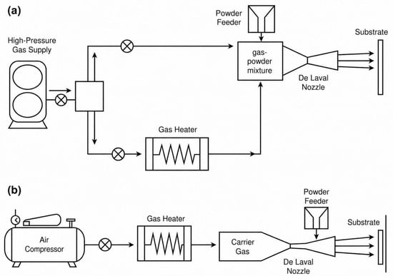
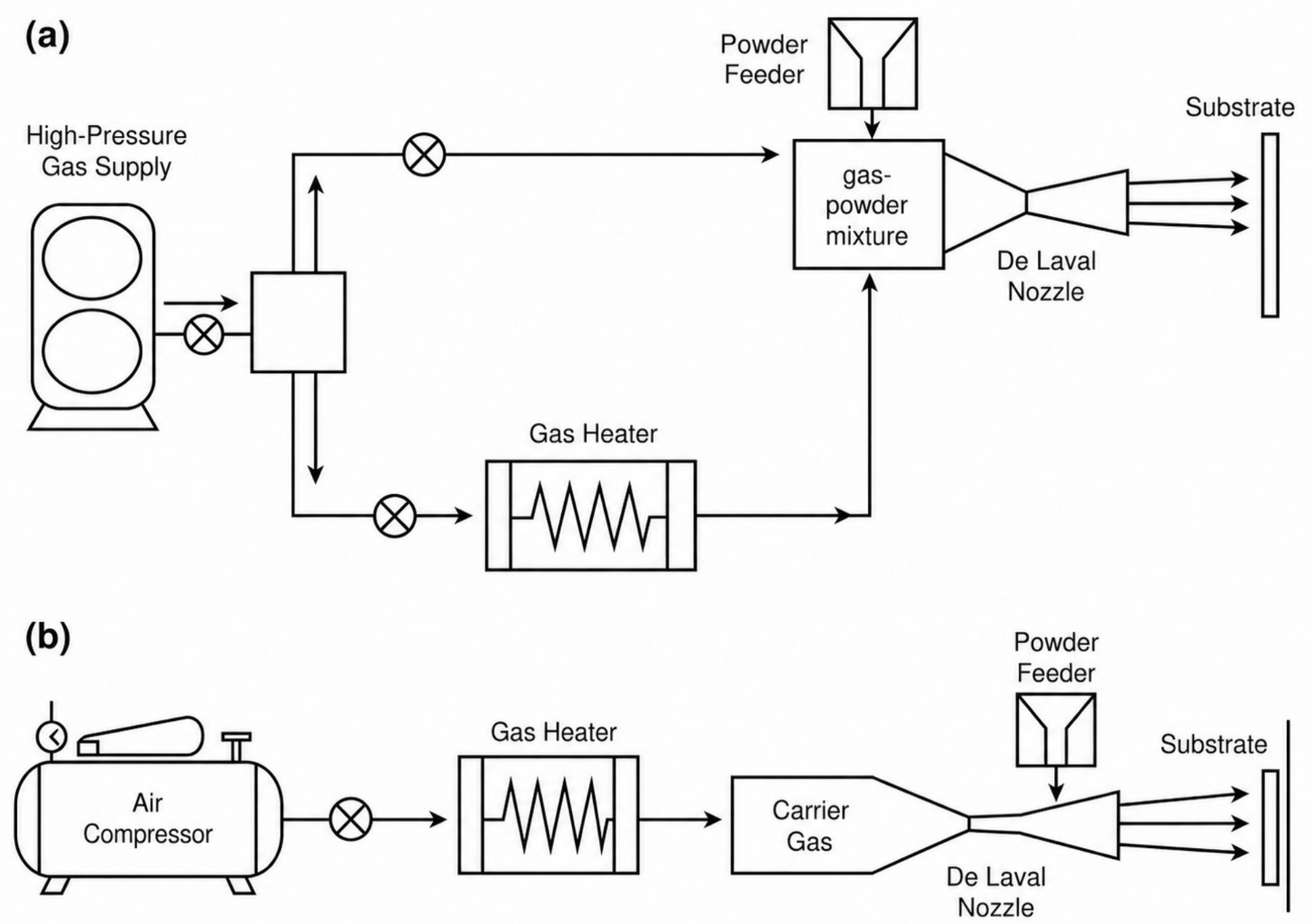
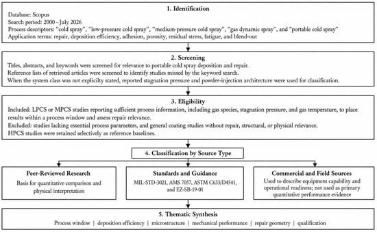
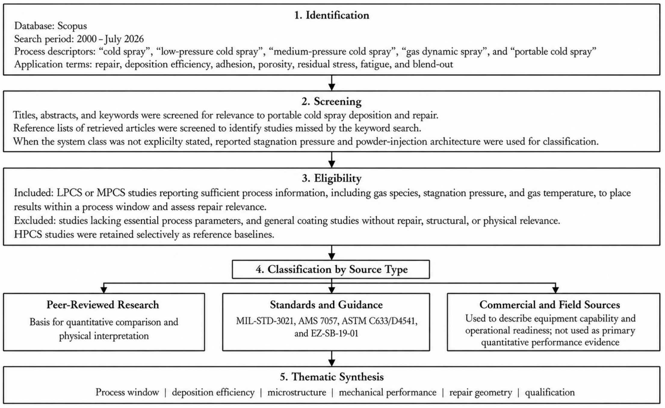
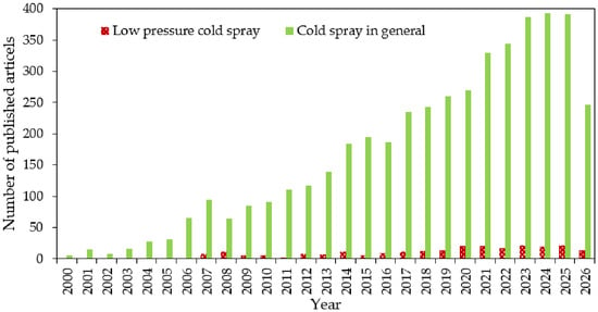
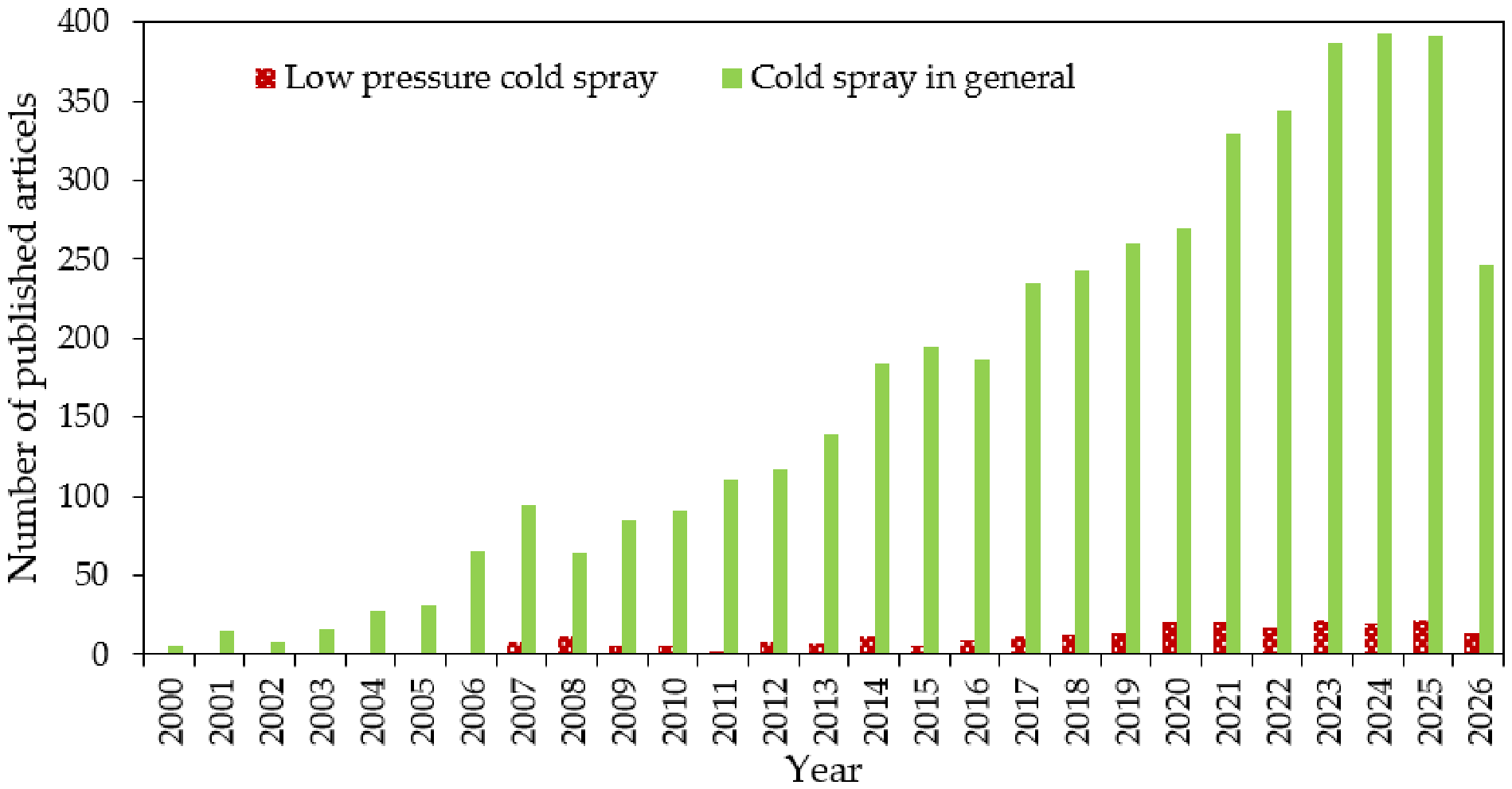
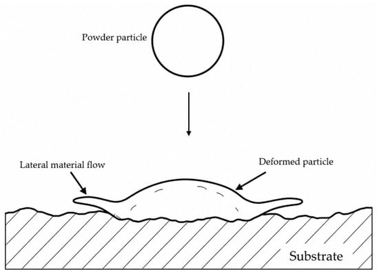
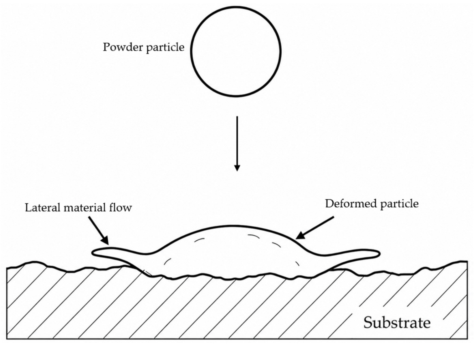
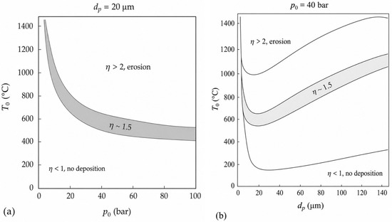
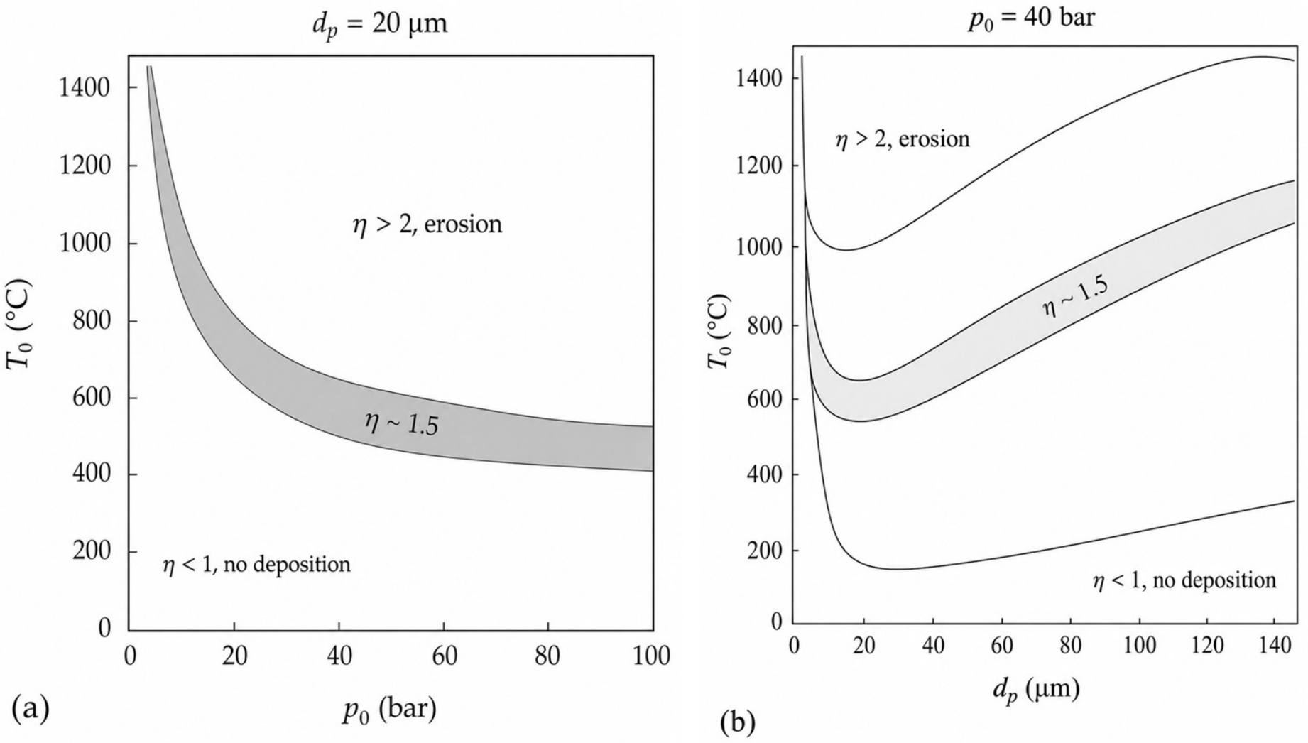
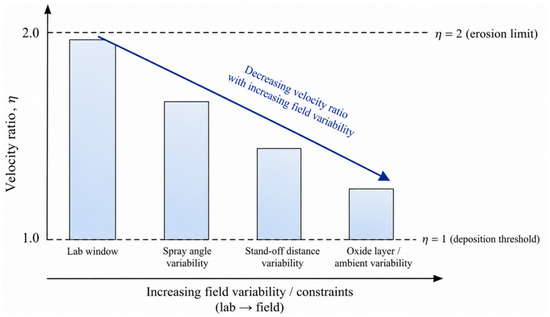
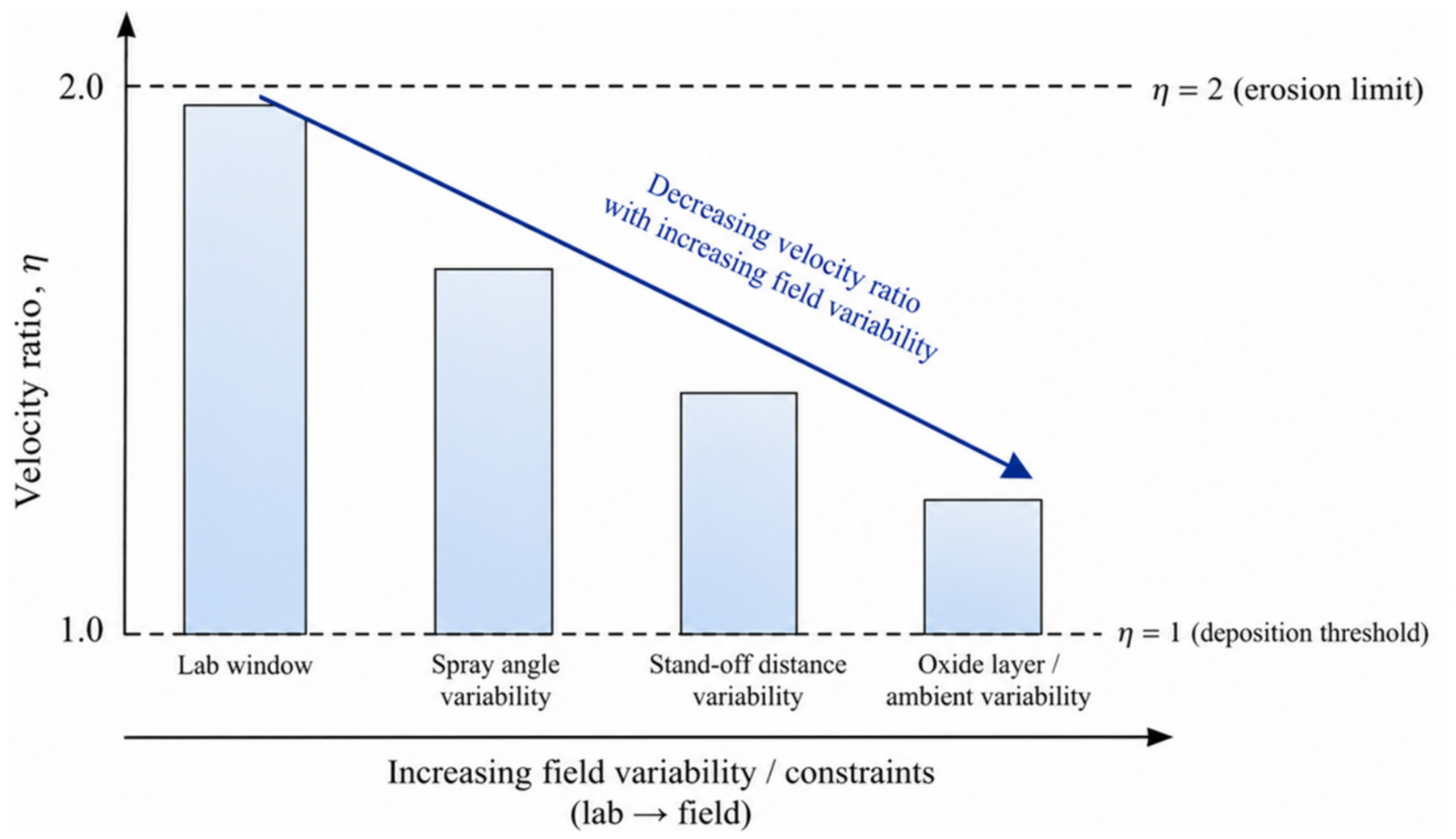
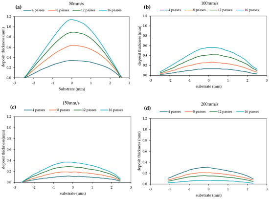
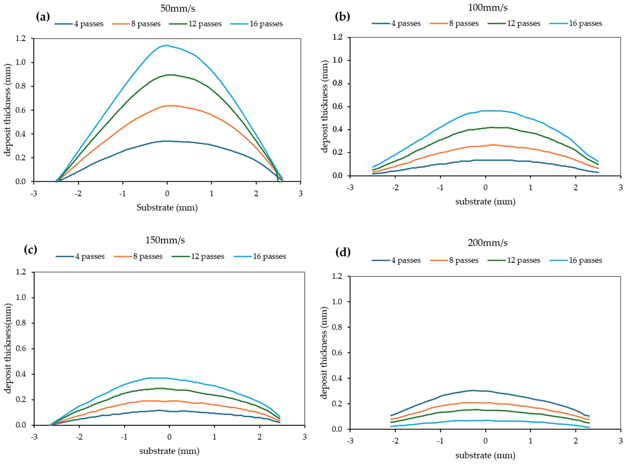
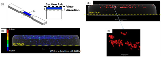
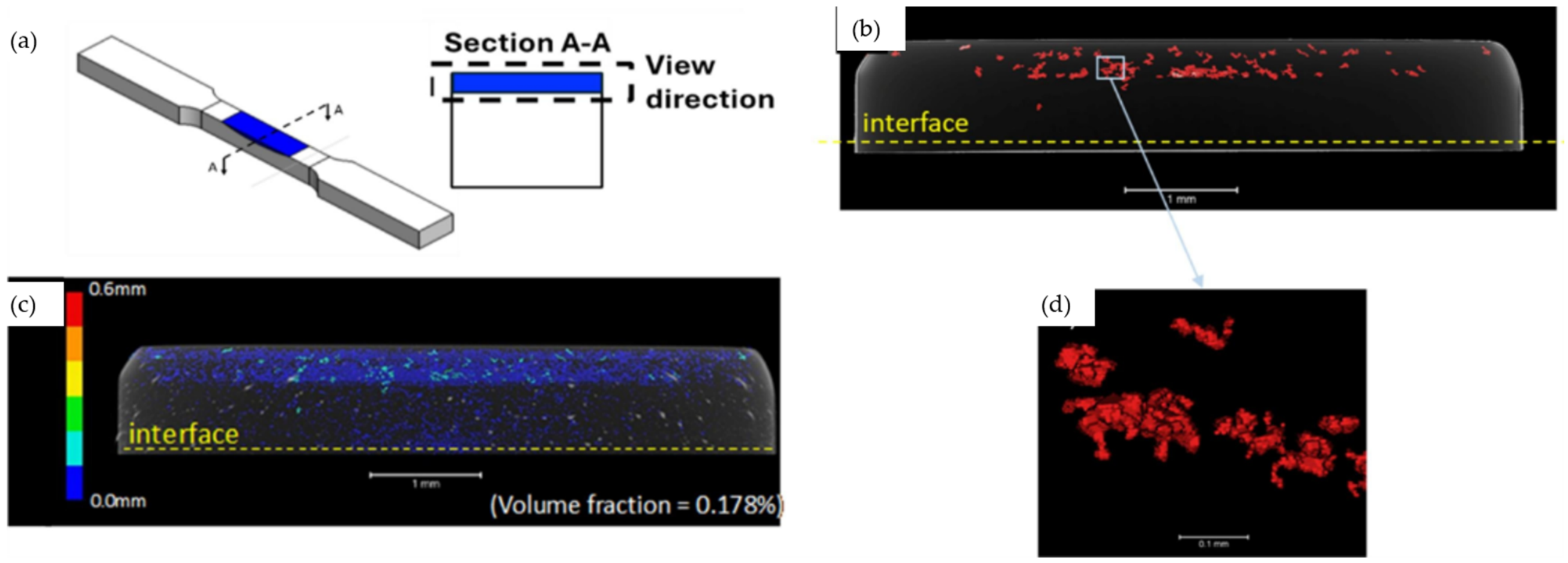
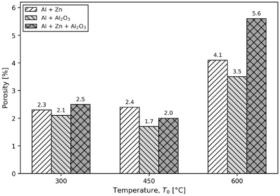
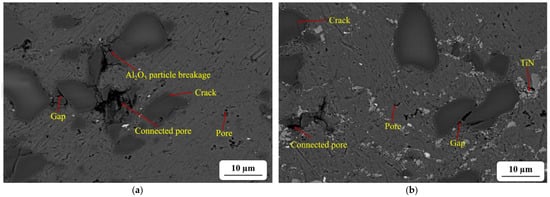
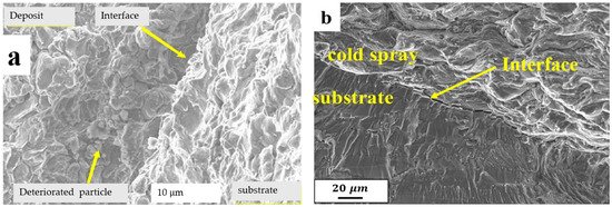
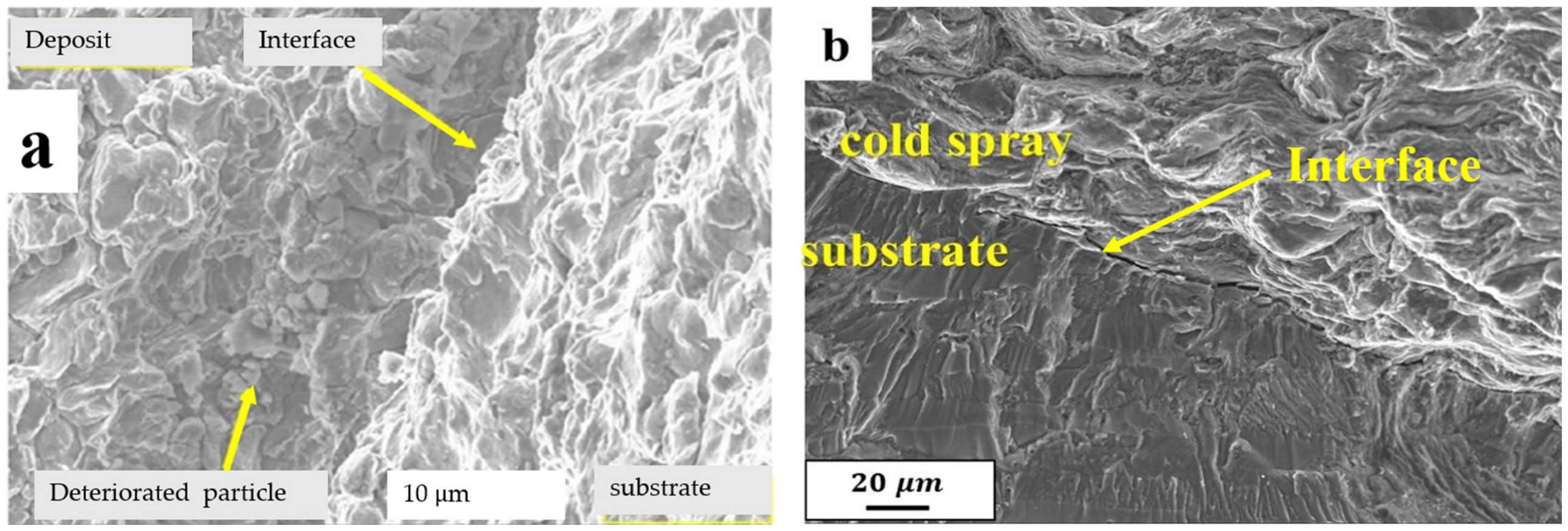
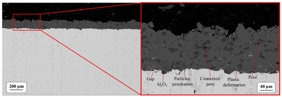
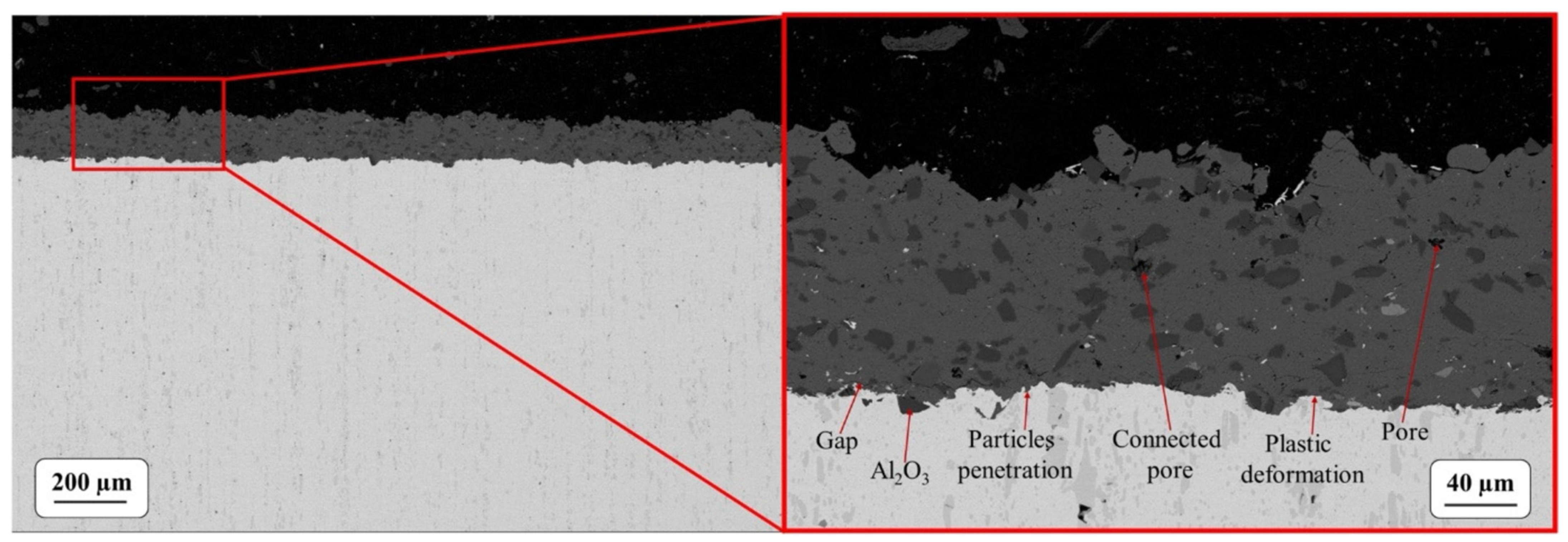
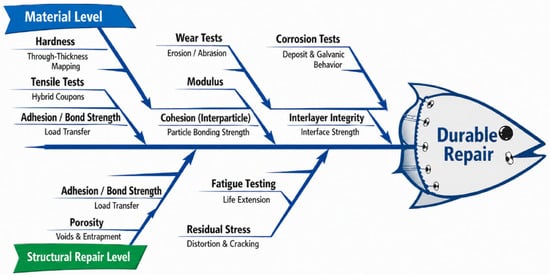
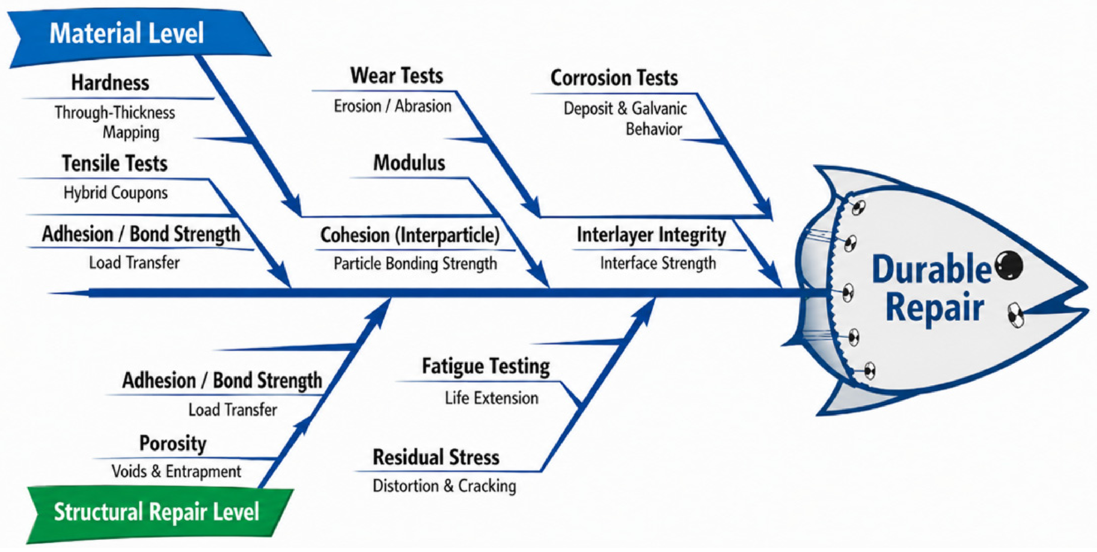
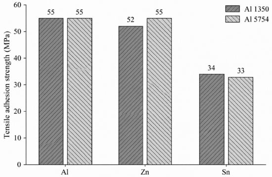
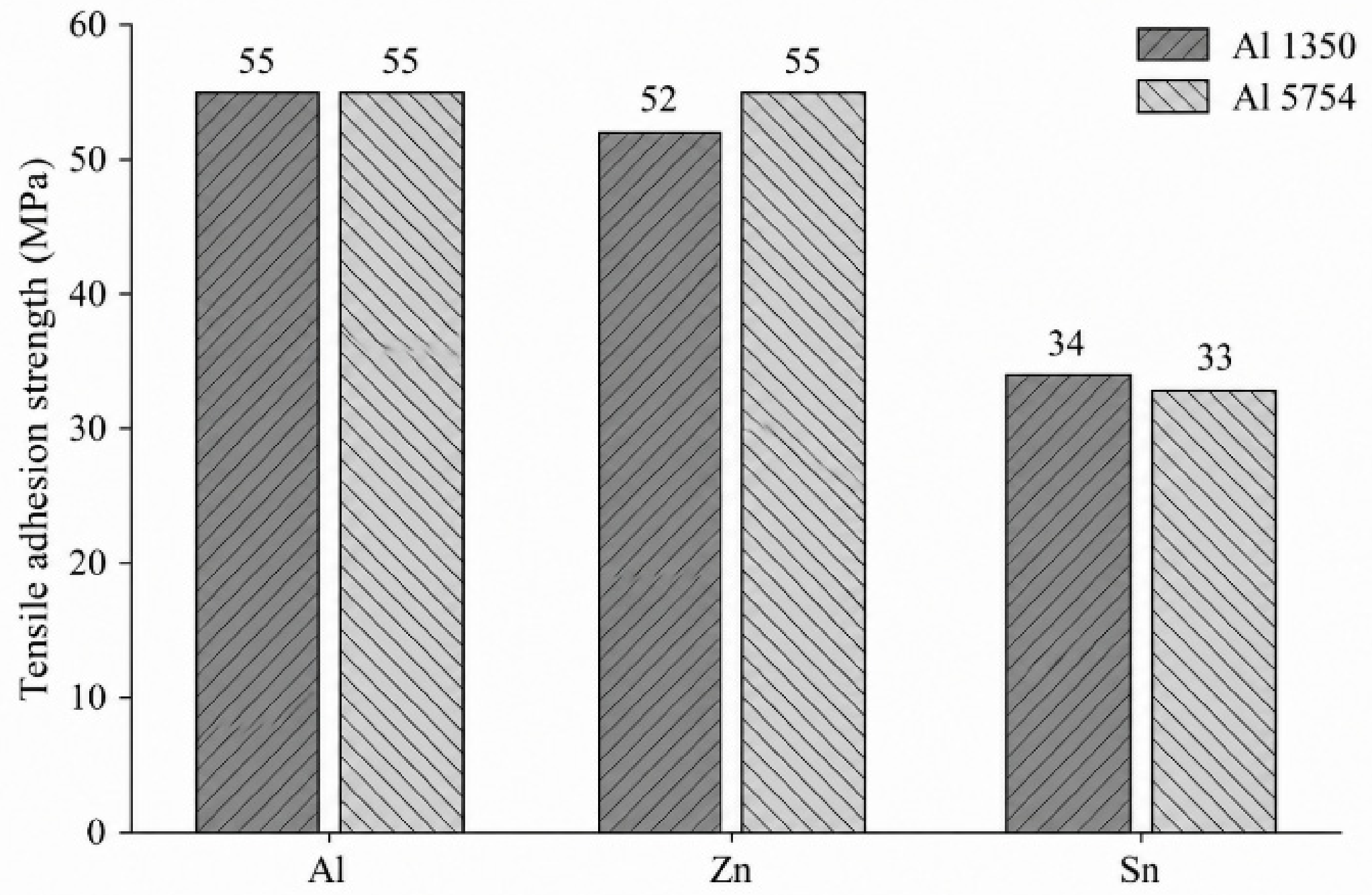
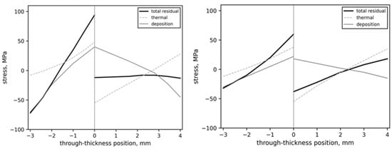
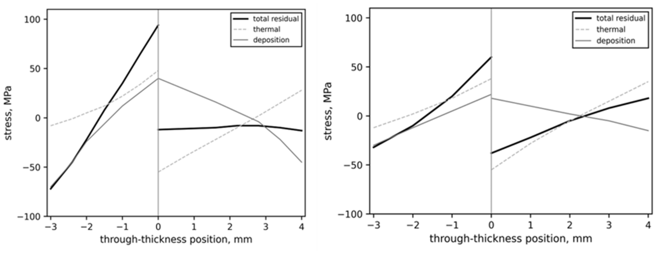
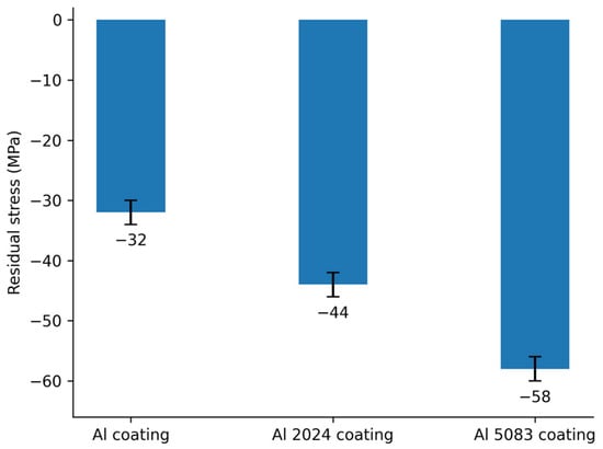
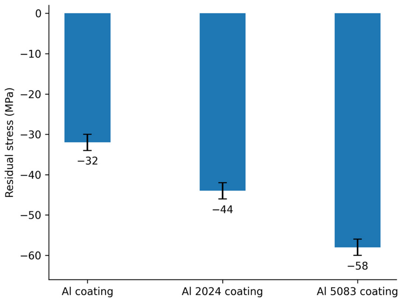
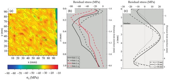
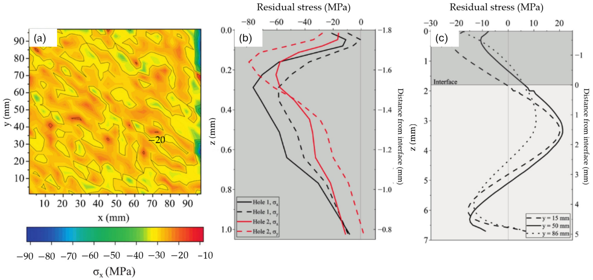
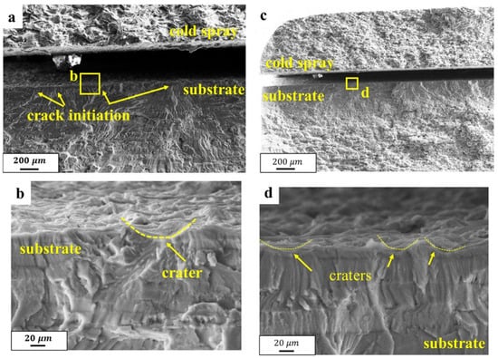
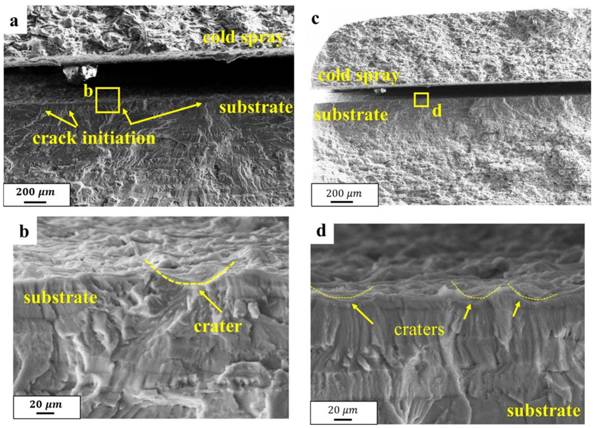
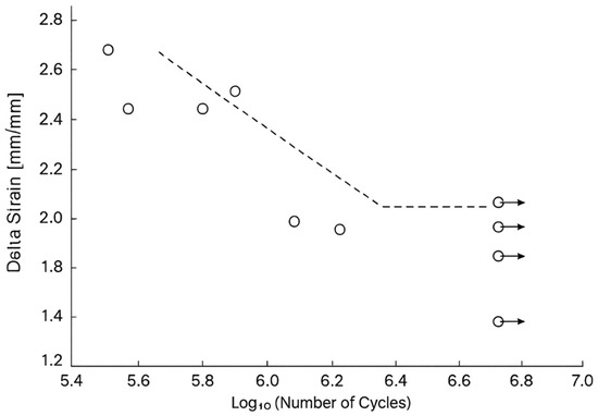
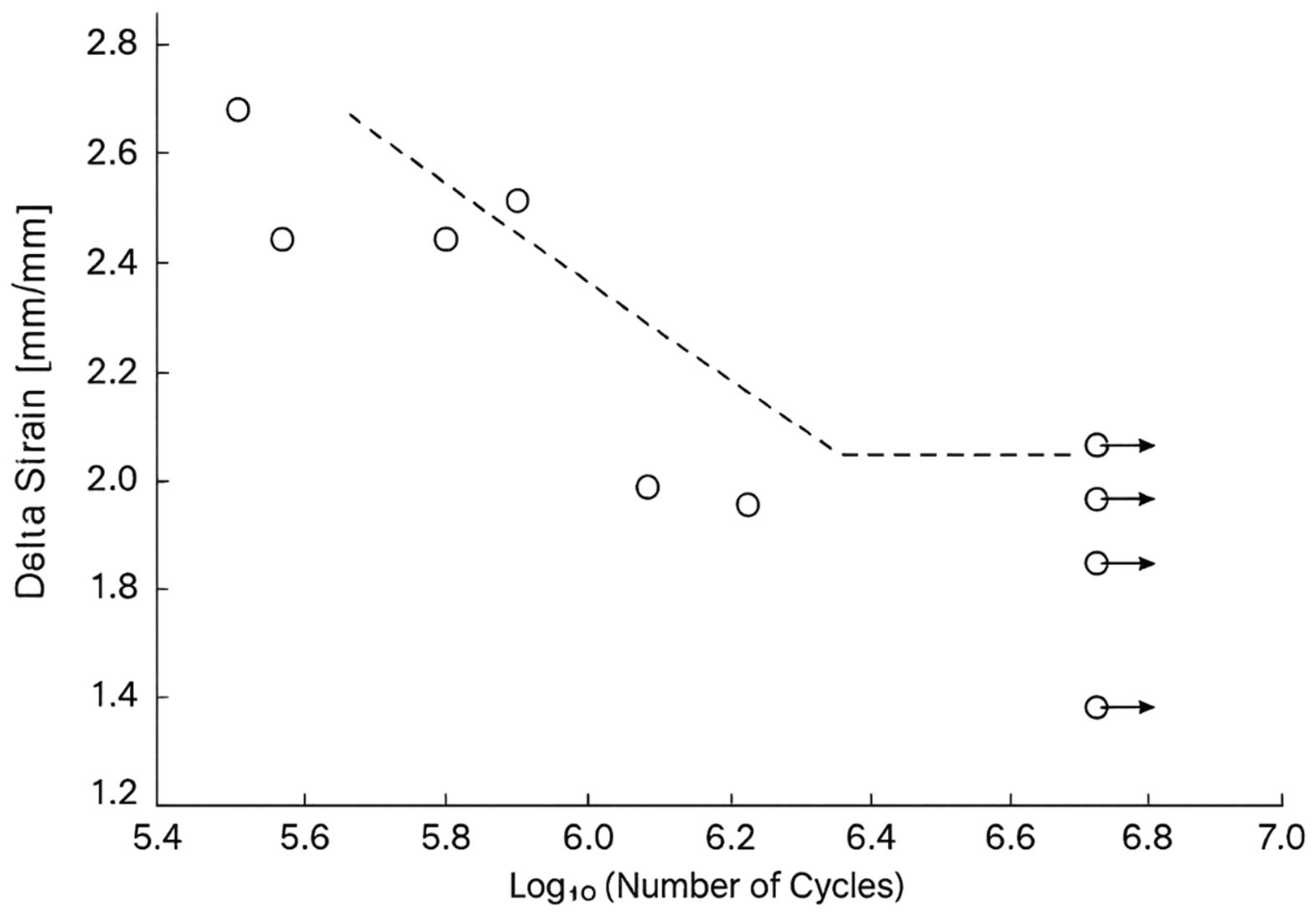
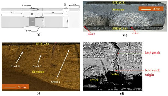
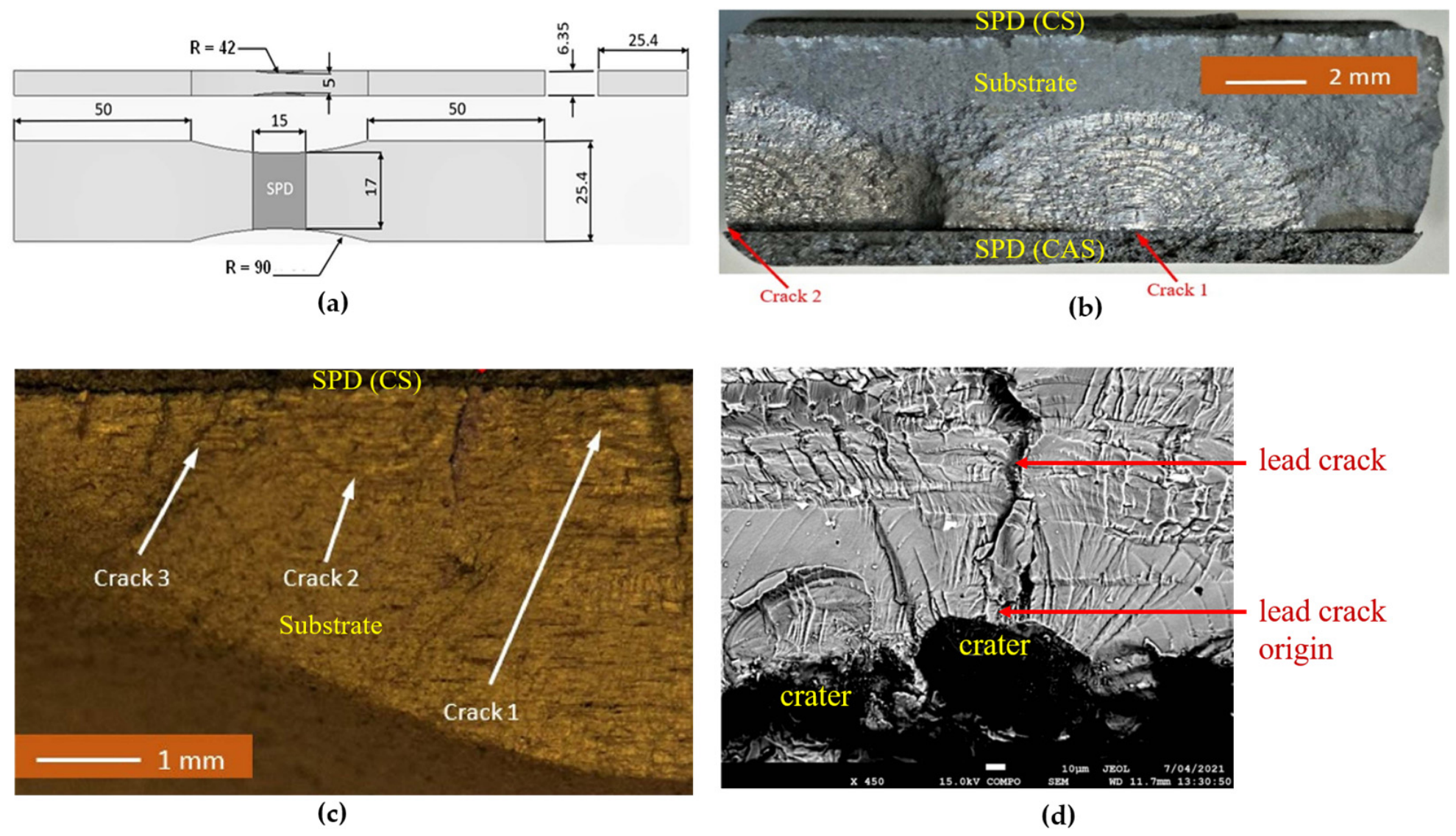
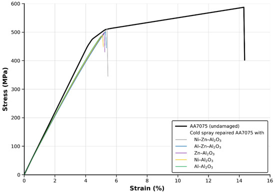
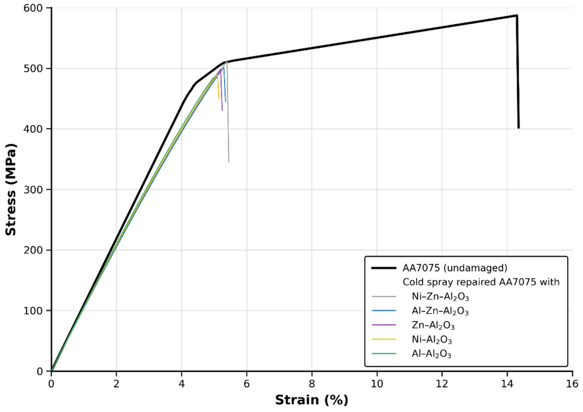
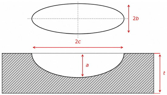
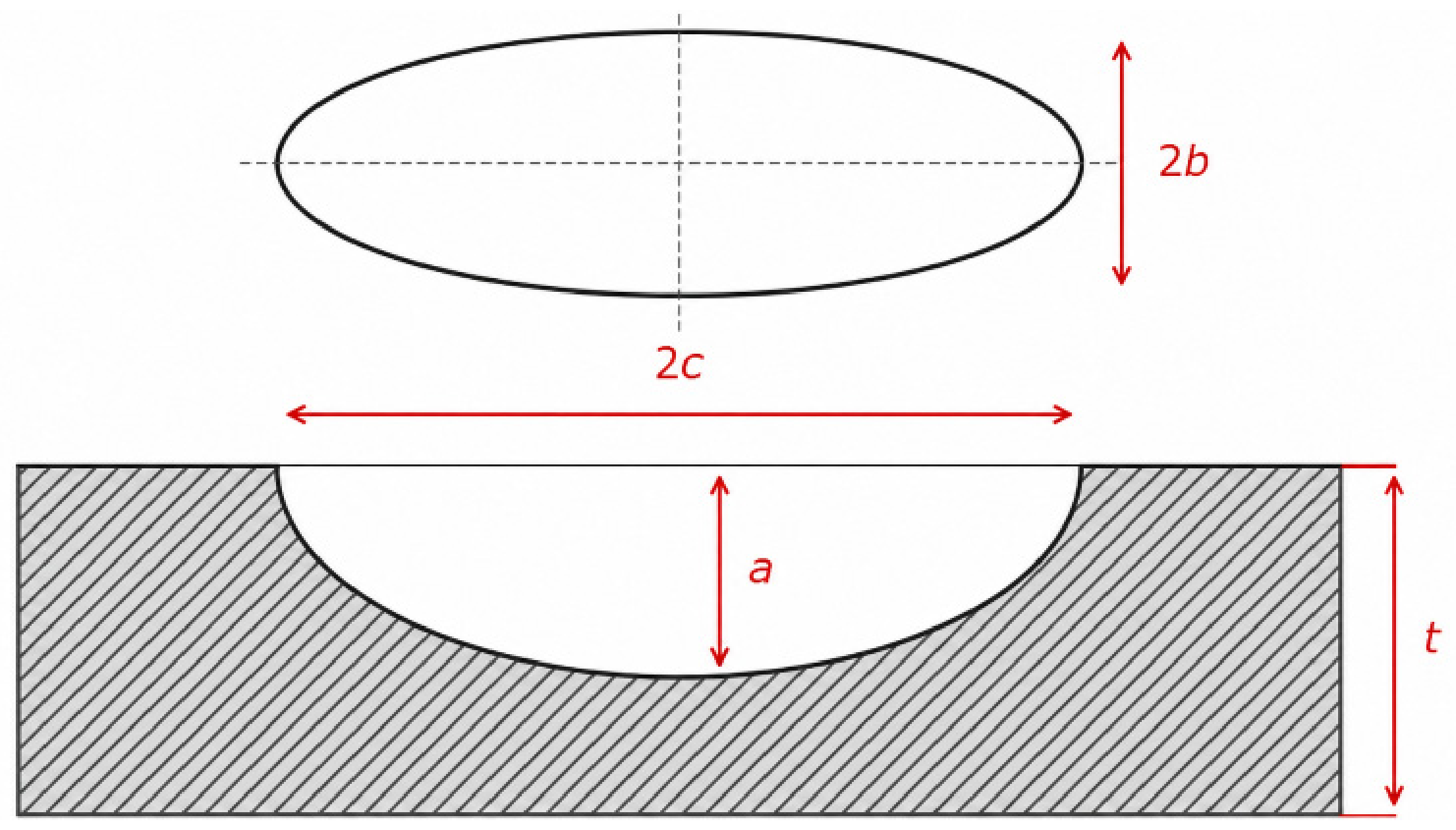
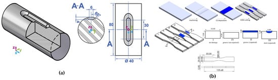
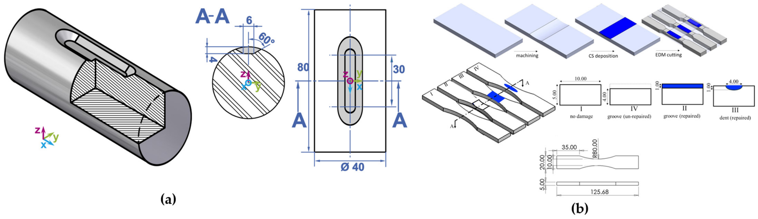
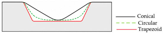
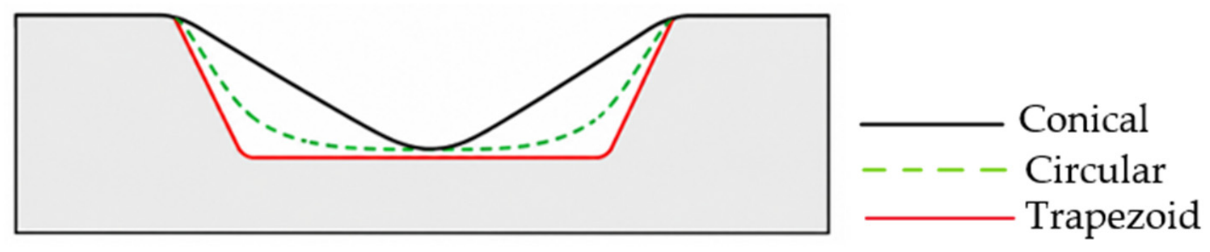
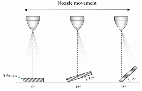
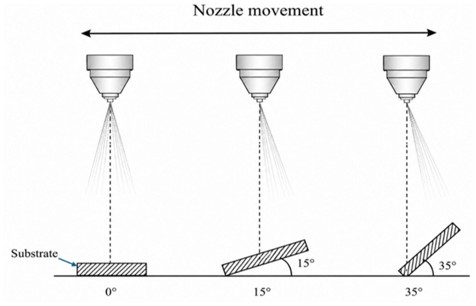
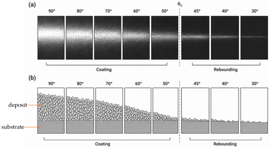
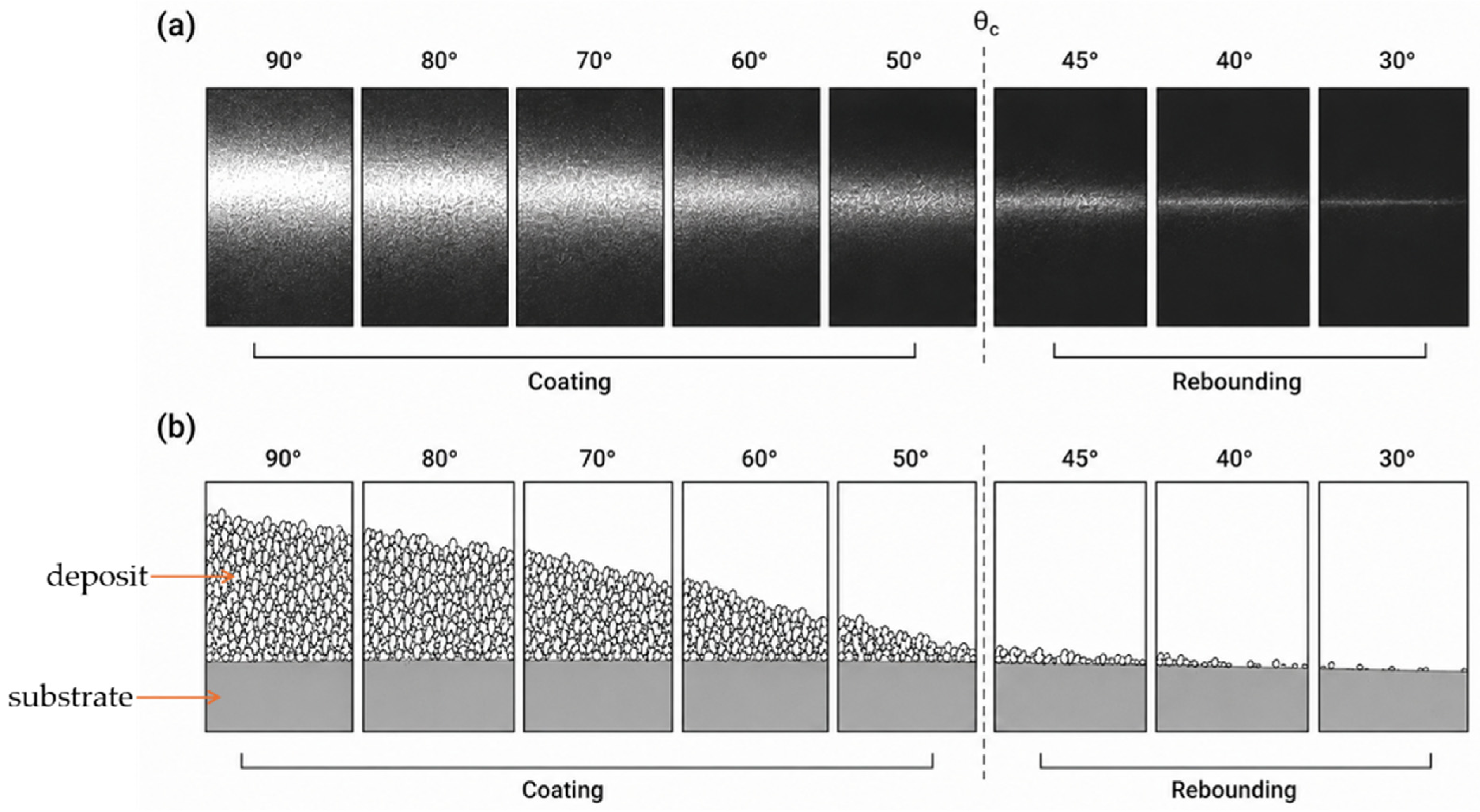

Disclaimer/Publisher’s Note: The statements, opinions and data contained in all publications are solely those of the individual author(s) and contributor(s) and not of MDPI and/or the editor(s). MDPI and/or the editor(s) disclaim responsibility for any injury to people or property resulting from any ideas, methods, instructions or products referred to in the content. |
© 2026 by the authors. Licensee MDPI, Basel, Switzerland. This article is an open access article distributed under the terms and conditions of the Creative Commons Attribution (CC BY) license.