


Abstract
The city of Veracruz preserves buildings mainly constructed during the 16th and 17th centuries, where carved madreporic coral was used as ashlar and as a component in mortars. These historic structures, now part of Mexico’s built heritage, show various degrees of deterioration caused by erosion and prolonged exposure to environmental elements. Restoration using original materials is currently nearly impossible due to ecological restrictions protecting coral reefs. In this context, and under the principles of the tailor-made technique, the present research revisits physico-mechanical and chemical studies conducted on the corals used in the construction of one of the most representative buildings in the city. The results were compared with those obtained from the formulation of experimental mortars using readily available materials—such as air lime, siliceous aggregates, and calcium carbonate—with the aim of reproducing the physical, mechanical, and chemical properties observed in the original corals. Laboratory tests allowed evaluation of their compatibility and performance, seeking to develop alternative materials that enable conservation interventions without compromising the integrity of the base material or the historic structures. The design of mortars is intended to be used in the restoration processes of buildings that are part of the built historical heritage. This is the starting point for understanding the characteristics of the mortar and its compatibility with the substrate, which could be used for repairing stone blocks and for preparing new mortars for masonry and plastering, since research on restoration mortars has largely overlooked this type of building with coral masonry due to its rarity. Therefore, this research is of particular interest. The mixtures formulated with calcareous sand were the most compatible with the reference coral material, while those made with silica sand exhibited properties superior to the corals, and marine sands showed very poor behavior, potentially compromising the integrity of the buildings. In physical–mechanical tests, formulations that include calcareous sand and silica sand (2 mm) demonstrated behavior closest to that of coral, consistent with chemical analysis results, where mortars formulated with calcareous sand registered the highest contents of CaO and portlandite. Mercury intrusion porosimetry indicated that the mortar formulated with silica sand (2 mm) has a porosity only 4.07% lower than that of the coral, while mortars formulated with calcareous sand and lime paste are between 11.17% and 16.87% lower. Therefore, one of the mixtures that stands out as the best option due to its similarity in physical–mechanical and chemical results is the composite that is not found at the extremes of the results obtained in the various tests carried out. The use of calcareous sand, as previously mentioned, enhances its behavior and affinity with the coral masonry, as demonstrated in the tests.
1. Introduction
The conservation and restoration of architectural heritage is a matter of great importance because it has shifted from preserving only the physical authenticity of monuments to a broader, value-based approach that includes social, economic, and environmental aspects. This evolution recognizes heritage buildings as important for community identity, sustainable development, and urban resilience by reusing embodied materials and energy. Modern conservation emphasizes collaboration among experts, local communities, and governments to balance historical authenticity with adaptive reuse for contemporary needs. Additionally, intangible values such as cultural identity and collective memory are increasingly integrated into conservation practices. The Athens Charter (1931)1 and the Venice Charter (1964)2 established a series of principles for intervention in historic monuments; these documents have not been upgraded since then. Over time, documents in the field of cultural heritage protection have been updated, establishing various rules and guidelines3. Today, heritage conservation and restoration practices require detailed studies of the techniques and materials used by ancestors—of which sometimes only remnants remain—to design interventions tailored to the nature of the buildings or remains to be preserved. This approach has attracted researchers from different fields to a new academic area focused on developing tailor-made materials specifically created to maximize compatibility—whether chemical, mechanical, or otherwise—with the substrates on which they are applied.
This work falls within that line of research. In this case, the aim is to develop a material capable of integrating optimally with some of the construction systems and materials used during the 16th and 17th centuries in New Spain and particularly in Veracruz, Mexico [1]. There, a hybridization in building methods occurred between the newcomers and the native population [2], evident in buildings such as the Casa Fuerte de Cortés or Fortaleza de la Villa Rica, in the town of Villa Rica, Veracruz [3] or the Castillo de San Juan de Ulúa (Figure 1), built on an islet on the La Gallega reef. Construction commenced at the early stages of colonization in Mexican territory until the late 16th century. This site was regarded as the principal gateway to the Americas, serving as the sole authorized port of entry into the country and the central hub for trade within the Viceroyalty of New Spain. Additionally, it functioned as the primary defensive stronghold for the protection of Mexican territory. Over time, the structure has undergone various functional transformations, having been utilized as the seat of the federal executive power, a powder magazine, and later as a prison. It was not until 1951, however, that its historical and cultural significance was formally recognized, when it was declared a Colonial Historical Monument by presidential decree. Subsequently, responsibility for its preservation was entrusted to the National Institute of Anthropology and History [4,5]. In these constructions, a material that has attracted interest for its unique properties was used: coral, extracted from nearby reefs. The stone known as mucara, muca, or mucar stone belongs to the Madreporaria family and was used both in the form of blocks and in powder. This powder was mixed with sand and weak lime to make a mortar used to join the blocks [6].
Figure 1.
Fortification of San Juan de Ulúa: (A) edge of the fortification without any coating, (B) general interior view of parapet in fortification, and (C) loss of coating and exposure of coral on parapet.
Nowadays, the extraction of this coral is prohibited due to its ecological impact [7] and the extensive damage already caused by extraction during the development of the city and the port [8,9], which makes restoration with original materials impossible. As an alternative to restoration using limestone blocks or brick, new restoration techniques have been proposed, among which the use of lime mortars with siliceous or calcareous sands, compatible with the corals, stands out. The materials were selected to compare a material with the capacity to form calcium carbonate, similar to coral, based on the findings of Pineda Campos [5], with a material of a different nature, silica sand, used as a reference. It is proposed that the calcareous material exhibits greater compatibility, in terms of affinity with the substrate, due to the presence of the common main component, calcium carbonate. The objective of this study is to evaluate how variations in aggregate composition and pore structure resemble or differ from those observed in the original coral substrate, particularly in terms of mechanical performance, porosity, and moisture transfer characteristics. Additionally, this study seeks to determine the chemical composition of the mortars and to assess their potential influence on their performance. Furthermore, the ease of acquiring the materials was considered a selection criterion in both cases. Additionally, beach sand was included as a reference material for the original mortars.
Research focused on the conservation and restoration of buildings made with masonry materials, especially coral stone, which faces significant challenges due to limited information and difficulties in using the original materials. To address these issues, the tailor-made materials technique has been employed, designed specifically for preserving heritage immovable properties. The tailor-made materials methodology involves developing materials with specific properties tailored to adapt appropriately to a given substrate. This process is carried out by multidisciplinary teams that integrate essential scientific knowledge to ensure that the new material is incorporated compatibly and safely into the monument without compromising the original structure’s integrity [10,11]. As Müller H. points out, “This requires appropriate methods that minimize intervention in the building fabric while ensuring durability and structural safety” [12].
Hao Y. highlights that the restoration of historic buildings is an interdisciplinary and highly complex process due to the multifaceted and multidimensional value of these structures and the variety of mechanisms that can cause their deterioration. Restoration plans must be developed and implemented based on cultural heritage protection principles to ensure coherence and effectiveness. Additionally, these plans should incorporate sustainability criteria and adapt to the surrounding environment to guarantee the conservation and reuse of historic buildings, thereby strengthening their cultural and historical significance [13].
Authors like Dorozhko have studied the techniques used in the construction, rehabilitation, and restoration of historical properties in architecture, highlighting that current technological solutions allow for their preservation and extended service life by protecting them against deterioration [14]. This work aims to rely on modern methodologies and equipment for investigating and evaluating both original materials and those intended for use in intervention processes, always prioritizing the conservation of the buildings, as emphasized by the author. Likewise, Pascua considers that each construction material should be treated as a specific case [15], making it essential to develop research and proposals tailored to each intervention situation, whether involving newly designed materials or the base materials of the building under intervention.
In this context, researcher Pineda Campos conducted an analytical study on the construction materials used in the Fortress of San Juan de Ulúa, located in Veracruz, Mexico [5]. The study included physical–mechanical resistance tests and chemical and mineralogical analyses. Due to the limited information available on the use of coral as a building material in historical constructions, Pineda Campos’s research serves as a valuable reference and a starting point for future investigations like the one presented here. The results obtained provide a solid foundation for developing conservation and restoration strategies aligned with the concept of tailor-made materials, which promote creating composites with better performance and minimal intervention on original materials.
Although there are many examples of the use of lime mortars for restoration, few focus on structures made of coral. Recent research has mainly focused on experimenting with mortars to improve performance in restoration processes, but the particular characteristics of the substrate material have been overlooked. Huaishuai Shang studies the improvement of Natural Hydraulic Lime (NHL) mortar for restoration using Ground Granulated Blast Furnace Slag powder (GGBFS/BFS) to analyze the impact of varying BFS (Blast Furnace Slag) content on the physical properties and microstructure of the repair mortar. Compared to the reference mortar, it requires less water for normal consistency, has a shorter setting time, lower water absorption, and less shrinkage. In terms of mechanical resistance to flexion and compression, this improved by 304% and 611% in the 28-day test. In addition, the incorporation of slag produces a pozzolanic reaction in the alkaline environment, which allows the formation of a Calcium Silicate Hydroxide (C-S-H) gel that acts by filling the pores of the mortar, improving densification, and, in turn, mechanical properties [16].
On the other hand, Zbyšek Pavlík, in his study of lime mortars, mentions the importance of considering the current state of the structures to be reconstructed and the properties of the original materials in their design and application. With this in mind, lime hydrate and natural hydraulic lime mortars partially lightened with chalcedony as a porous aggregate, as an alternative filler to silica sand, are designed and evaluated experimentally. Their application made it possible to achieve values for porosity, compressive strength, water absorption coefficient, and water vapor diffusion resistance factor in accordance with the criteria established in recommendation WTA 2-9-03.2020/E4. In conclusion, given the type of binder used and the level of mechanical strength required, the mortars analyzed can be considered suitable materials for the repair of historic masonry affected by moisture and salts [17].
Furthermore, as mentioned above, when preparing mortars for restoration work, the specific characteristics of the materials used in historic masonry with which they will interact must be taken into account. In the research carried out by Maravelaki Kalaitzaki [18], a detailed analysis of the original materials present in the historic structures was carried out, determining that the mortars were mainly composed of magnesia lime, in a region characterized by the presence of dolomites. Based on these results, natural hydraulic lime (NHL) was used as a binder, together with silica sand and crushed brick aggregates. The mortars obtained showed favorable performance and parameters compatible with conservation requirements, notably the absence of soluble salts. This approach has made it possible to develop mortars with properties similar to those of the original material, minimizing the risk of deterioration in historic structures and reinforcing the concept of tailor-made materials for the conservation of built heritage.
The physical and mechanical characterization of mortars used in buildings belonging to the historical heritage is a fundamental aspect in the selection of materials for their intervention and conservation. In accordance with this premise, Magalhães A. develops his research on the study of ancient Portuguese mortars, presenting and analyzing the results obtained from their characterization. The author describes in detail the test methods used to evaluate the behavior of mortars when exposed to water and their compressive strength, comparing the results with those obtained in contemporary mortars, both using the same experimental procedures and through the methods recommended by European standards (EN 1015-18 and EN 1015-11) [19]. In his conclusions, Magalhães emphasizes the need for comprehensive information on the physical, mechanical, and chemical properties of mortars in order to properly adapt the formulations of repair materials and accurately assess their state of preservation.
In this research, materials similar to corals, consisting mainly of calcium carbonate (CaCO3), were used. For this purpose, air-type lime was used as the raw material, formulating composites with silica and calcareous sand aggregates. The study conducted by Pineda Campos [5] was used as a reference to establish the chemical and physical–mechanical characteristics of the corals, following the criteria proposed for tailor-made materials.
In this context, the present research addresses the lack of specific solutions for the restoration of structures built with madreporite coral, a material whose extraction is currently prohibited and whose original mechanical and hygrothermal behavior is difficult to reproduce with conventional products. Following a tailored materials approach, lime-based compounds were formulated using siliceous and calcareous aggregates to obtain mortars with physical, mechanical, and hygrothermal properties compatible with the coral substrate, composed primarily of calcium carbonate. The selection of these materials was based on their potential to mimic the porous structure and moisture transfer characteristics of the original coral masonry, while ensuring technical feasibility and availability for practical intervention.
This work included the physical–mechanical and chemical characterization of the formulated compounds, using European standards adapted to the specific mortar testing requirements. The results were evaluated by comparing them with those reported by Pineda [5] to determine feasibility and select the most suitable compound for the restoration of buildings constructed with coral masonry. The study aims to provide a viable alternative for the conservation and restoration of madreporite coral structures, an area that currently lacks optimal intervention solutions. This initial research presents results for proposed mortars to initiate the future development of mortar blocks designed for the restoration of heritage structures built with coral, which possess a calcium carbonate exoskeleton. These blocks are intended for integration into walls, with the goal of achieving mechanical and physical properties similar to those of the original corals used in the heritage construction.
2. Materials and Methods
2.1. Materials
For this study, the materials used for sample preparation consisted of the following (Table 1):
Table 1.
Composition of mixtures and density.
- -
- Lime paste and powder from various suppliers, and a paste product that has an aging period of between six months and four years. Its manufacture complies with the UNE-EN 459-1 standard [20]. Five types of lime were used, all of which set and harden through carbonation of CO2 in the air:
- ∘
- Powdered lime:
- ▪
- Lime 1 (CL-90): calcium lime according to EN 459-1:2015, which comes from the calcination of limestone.
- ∘
- Lime paste: All limes were obtained by calcining limestone, followed by hydration and subsequently slaked to produce paste (calcium hydroxide).
- ▪
- Lime 2 (CLG): Gordillos lime—Morón lime. Aging time at the time of use: 7 months.
- ▪
- Lime 3 (CLPR): PROIESCON lime. Aging time at the time of use: 4 years.
- ▪
- Lime 4 (CLU80): UNICMAL lime with a particle size of 80 microns. Aging time at the time of use: 2.5 years.
- ▪
- Lime 5 (CLU200): UNICMAL lime with a particle size of 200 microns. Aging time at the time of use: 13 months.
- -
- Water from the Canal de Isabel II (Madrid), in accordance with the technical specifications set out in UNE-EN 196-1 [21].
- -
- Sand: Different types of sand were used, mainly silica and calcareous:
- ∘
- Silica sand:
- ▪
- Sand 1 (A-0,2): silica sand from SODIRA 0.2, with a particle size distribution of less than 2 mm.
- ▪
- Sand 2 (A-0,4): silica sand from SODIRA AF-0/4-M-S-L, with a particle size distribution of less than 4 mm.
- ∘
- Calcareous sand:
- ▪
- Sand 3 (A-CLC): calcareous sand from the SODIRA AF-0/4-T-C mine, with a particle size distribution of less than 4 mm.
- ▪
- Sand 4 (A-CM): beach calcareous sand from Cala Mundina (Spain), with a particle size distribution of less than 4 mm.
2.2. Test Specimen Preparation
Since there is no specific standard procedure for mortars made with lime paste, this research relies on methodologies established in current standards for other composites, particularly UNE-EN 196-1 [21] and UNE-EN-1015-2 [22], to facilitate replication of tests in future studies. Several series of three prismatic specimens (40 × 40 × 160 mm3) were prepared and tested at 28 and 180 days (Table 1). UNE-EN 196-1 specifies material proportions for preparing reference mortars and serves as a basis to establish an equivalent volume of sand for other mixes by measuring the volume of standardized CEN sand in a 500 mL container, repeated at least three times to average and set a reference level. Selected sands must match this volume to ensure comparability. The equivalent sand mass is then weighed and averaged to adjust the water-to-lime ratio in consistency tests. Since lime paste already contains water, the water-to-binder ratio is not applied; instead, the goal is to achieve a flow spread of 175 ± 10 mm, as indicated in UNE-EN 1015-2, by adjusting the mass of lime paste accordingly.
The choice of powdered or putty lime combined with well-defined silica sands and calcareous sands allows for an accurate assessment of the influence of aggregate particle size distribution and mineralogical nature on mortar behavior.
Table 1 presents the composition of the mortars, beginning with those made with powdered lime mixed exclusively with silica sand, with the aim of characterizing their behavior in comparison with mortars made with lime putty, silica sand, limestone from the mine and beach sand; lime paste and beach sand which are of greater interest based on current knowledge of mortars used at the time of construction of buildings in Veracruz, Mexico [5].
On this basis, it is considered that aged lime slaked under water develops smaller, laminar Ca(OH)2 crystals, improving the binder texture, and that mortars produced with aged lime putty carbonate more rapidly and extensively, reduce their porosity, and become denser and stronger [23,24]. Consequently, for the mortars with the longest aging times, CLPR and CLU80, aged four and two years, respectively, beach sand (A-CM) was selected, since there is not enough material available to produce mortars for all mixtures due to its origin.
The lime and aggregate content is not identical in all mixtures; however, the compositions were intentionally modified with two main objectives: (i) to maintain the binder-to-aggregate volumetric ratio as established by the reference standard and (ii) to systematically analyze the influence of the main variable, such as the type of lime, aggregate type, or particle size distribution, on the physical–mechanical and chemical behavior. Consequently, the comparison between the mortars is valid, since all mixtures were designed under the same regulatory criteria and with equivalent volumetric proportions, differing only in the parameters under study.
The procedure for preparing the specimens began with weighing the materials. Immediately afterward, the mixer started at a slow speed. After 30 s of mixing, the sand was gradually added over another 30 s. The mixing speed was then increased to high for an additional 30 s. Subsequently, the process was stopped for 90 s to remove and recover mortar adhered to the walls and bottom of the container during the first 30 s. Finally, mixing resumed at high speed for 60 s to ensure a homogeneous mixture [21].
Once mixing was completed, the mixture was poured into the molds. To prevent the formation of air bubbles, the process was carried out in two layers (lifts), each compacted with 25 strokes. Excess mortar was then removed, and the specimens were transferred to a dry, cool place on a horizontal surface. During the curing period, the test specimens are kept in a dry and cool space at a temperature of 20 °C (+3 °C/−2 °C), maintaining a relative humidity of 95% (±5%) while in the mold for 5 days. The relative humidity is maintained for 2 more days after removal from the mold. For 21 days, the test specimens are kept at a relative humidity of 65% (±5%), according to the guidelines of UNE-EN 1015-11 [25]. Finally, the demolded samples stayed on the metal mesh during curing until reaching 28 or 180 days before testing.
2.3. Experimental Plan
To preserve the original construction techniques and materials used, Pineda Campos makes a valuable contribution by analyzing six different types of scleractinian corals, identified as the main ones used in buildings constructed in the city and port of Veracruz, Mexico. The study presents results related to the physico-mechanical and chemical properties of these materials [5]. These findings serve as a reference to compare with those obtained in the present study.
The experimental plan was carried out in two phases. The first phase took place in the materials laboratory of the Escuela Técnica Superior de Edificación. The second phase was conducted in the chemical analysis laboratory of the Escuela Técnica Superior de Ingeniería y Diseño Industrial. Both laboratories are part of the Universidad Politécnica de Madrid.
2.3.1. Phase 1: Physical–Mechanical Tests on Lime Mortar Specimens: The Physical and Mechanical Characterization of the Composites Was Performed Using Shore D Surface Hardness, Young’s Modulus, Flexural Strength, and Compressive Strength
Shore D surface hardness (UNE 102,042 [26]) (UNE-EN 13279-2 [27]): The test is performed on the two longitudinal sides of the 40 mm × 40 mm × 160 mm prismatic test piece. A durometer is used to measure the Shore D hardness of the test pieces, applying force at least three points located at ¼ of their length and 20 mm from the ends (Figure 2). The arithmetic mean of the measurements is then calculated, discarding any values that are not between 0.9 and 1.1 of that mean (Figure 3A).
Figure 2.
(Left) lime in pasta; (right) aggregate. Source: Author’s own creation.
Figure 3.
(A) Shore D surface hardness test; (B) flexural strength test; (C) compressive strength test.
Dynamic Young’s Modulus: the Ibertest Ultrasonic Tester E46 was used, operating at a frequency of 50 kHz. To do this, the method described in the UNE-EN 12504-4 standard [28] was followed, applying an industrial-grade gel to each of the faces where a transmitter and receiver were placed. This favored the longitudinal transmission of sound waves, which allowed the measurement of the transit time between these faces. After recording the propagation speed of the ultrasonic waves in the test tubes, their dynamic modulus was calculated using the following mathematical expression:
where
ED is the dynamic modulus of elasticity (MN/m2);
V is the speed (Km/s);
Q is the density in (Kg/m3).
Flexural strength (UNE-EN 1015-11 [25]): the Ibertest Autotest 200-10SW testing machine was used to apply a progressive load until the specimen reached its breaking point. Each of the prismatic specimens was placed in the testing machine with one of its side faces resting on the lower rollers (whose centers are 100 mm apart) (Figure 4). The load is applied by means of an upper roller to the center of the test piece until breakage occurs. The maximum load in Newton units was then recorded, and the load-deformation data obtained during the test were recorded and stored in the associated software (Figure 3B). The flexural strength is given by the expression
where
Figure 4.
(Left) preparation of mixtures in molds. (Right) unmolded samples.
f is the flexural strength (N/mm2);
F is the maximum load applied to the test piece (N);
l is the distance between the support rollers (mm);
b is the width of the test tube (mm);
d is the depth of the test tube (mm).
Compressive Strength (UNE-EN 1015-11 [25]): as with the flexural strength test, the Ibertest Autotest 200-10SW testing equipment was used, applying a progressive load until the test piece reached its breaking point. For the test, one of the halves obtained in the flexural test was used, placing it with its side faces between two steel plates with a cross-section of 40 × 40 mm2 (Figure 3C), and a load was applied until it broke, noting the maximum value in Newtons, recording and storing the load-deformation data obtained in the associated software. The compressive strength is given by the expression:
where
Rc is the compressive strength in N/mm2.
Fc is the maximum load supported, in newtons (N).
1600 is the cross-sectional area of the support plate, in mm2.
2.3.2. Phase 2: Chemical Tests on Raw Lime and Selected Lime Samples: Once the Composites with Physical and Mechanical Properties Most Similar to Those of Madrepore Corals Had Been Selected, the Raw Material Was Chemically Characterized Using Elemental Analysis, Thermogravimetric Analysis, and X-Ray Diffraction, and the Porous Structure of the Composites Was Characterized by Using Mercury Porosimetry
Elemental Analysis of Composites (XRF) was performed using a Bruker S2RANGER X-ray fluorescence (XRF) spectrometer. This equipment is equipped with a dispersive energy detector and an X-ray tube with a palladium (Pd) anode. The EQUA-OXIDES measurement protocol was used. The sample was prepared for analysis by mixing and pressing 9.2 g of powdered material with 0.8 g of wax binder. The Loss-of-Ignition (LOI) parameter of the composites was determined at a final temperature of 1050 °C.
Thermogravimetric Analysis (TGA): The analysis was performed on raw lime and selected composites to determine the mass change as a function of temperature (weight loss) and the associated thermal effects. A TA Instruments SDT Q600 thermobalance was used for this purpose. Lime paste samples were preconditioned at 40 °C for 24 h in a J. P. Selecta, S.A. oven before analysis. Powdered lime samples and dried lime paste samples were sieved through a 0.3 mm mesh sieve prior to thermogravimetric analysis, and the composites were ground and sieved with the same mesh. The test was conducted under a controlled air atmosphere with a flow rate of 100 mL/min and a heating rate of 10 °C/min. This procedure allows monitoring of thermal decomposition and related mass changes in lime-based materials.
X-ray diffraction (XRD) was performed using a Siemens Krystalloflex D5000 diffractometer. The equipment used Cu Kα radiation (1.2) and was equipped with a graphite monochromator to filter the radiation. Crystallographic analysis was conducted on powdered lime samples and dried lime paste samples, all of which were previously sieved through a 0.3 mm mesh sieve. The composites were ground and then sieved with the same mesh prior to analysis. The diffractogram was obtained over a range of 5° ≤ 2θ ≤ 50°, with steps of 0.04° and an acquisition time of 4 s per step.
Mercury Intrusion porosimetry (MIP): Porosity and pore size distribution analysis of the specimens was performed. Measurements were conducted on fragments of half-specimens obtained after mechanical fracture tests. A Quantachrome P POREMASTER 60GT device was used for the analysis. This method involves the forced intrusion of mercury (Hg) into the porous network of the samples by applying controlled pressure. The measured pore size range spans from 900 microns in diameter down to less than 3.5 mm.
3. Results and Discussion
3.1. Phase 1: Physical and Mechanical Tests on Lime Test Specimens
3.1.1. Shore D Surface Hardness
Figure 5 shows the results obtained in the Shore D surface hardness test. In general, the hardness of all samples increases as the days pass since their manufacture.
Figure 5.
Shore D hardness values obtained in the composites at 28 days (left column) and the composites at 180 days (right column).
Specifically, the evolution of Shore D hardness between 28 and 180 days evidences differentiated behaviours as a function of the lime–aggregate combination. At 180 days, composites with CL-90 lime and A-0,2 or A-0,4 silica sand show a moderate increase of 5.10% relative to 28 days (from 52.16 to 54.96), whereas the increase is markedly higher (22.91%) for CLG composites with A-0,4 and A-CLC calcareous sand (from 28.13 to 36.49). Intermediate gains are observed for CLPR with A-0,4 and A-CLC sand (+4.72%; 46.18 to 48.47) and for CLU80 with A-0,4 and A-CLC sand (+1.16%; 56.16 to 56.82). In contrast, CLU200 composites with A-0,4 and A-CLC sand exhibit a slight reduction in hardness (−2.83%; 57.57 to 55.99), and the mixtures CLPR A-CM and CLU80 A-CM undergo more pronounced losses of 17.80% (50.30 to 42.70) and 26.24% (55.80 to 44.20), respectively.
These trends are consistent with the expected time-dependent mechanical development of air lime mortars, in which carbonation and, in some formulations, the formation of secondary hydraulic products progressively densify the microstructure and increase internal cohesion [29,30,31]. The more pronounced increases in hardness for some calcareous aggregates suggest more efficient microstructural refinement, whereas the decreases observed in A-CM mixtures point to microstructures with higher effective porosity or weaker matrix–aggregate bonding, which limit long-term hardening.
Comparison between aggregate types highlights a clear influence of mineralogy and particle characteristics on surface hardness. Among the composites with silica sand, the CL-90 A-0,2 mixture attains the highest Shore D values, exceeding those of most calcareous sand mortars, with the exception of CLU80 A-CLC, which reaches comparable hardness. This behaviour agrees with Du and Treviño [32,33], who report that final mortar hardness depends not only on aggregate mineralogy but also on granulometry, particle shape, and surface roughness. For the mortars prepared with lime putty, the highest hardness values within each lime group are systematically associated with A-CLC (limestone mine) sand, indicating that this aggregate favours greater packing density and a reduced volume of connected pores, in line with its specific physical properties [32,33].
Overall, the data support a hierarchy of mechanical response: mixtures with A-CLC sand > lime with A-0,2 silica sand > composites with CLG lime and A-CM sand. Within this sequence, mortars incorporating limestone mine sand—particularly CLU80 A-CLC—exhibit the highest Shore D hardness, while formulations based on CLG lime constitute the least hard group. This ordering underscores the dominant role of aggregate type, in combination with lime class, in controlling the hardening kinetics and final surface hardness of air lime mortars.
3.1.2. Young’s Modulus
Figure 6 shows the average Young’s modulus values obtained from tests carried out on test specimens corresponding to the different composites.
Figure 6.
Dynamic Young’s modulus of the composites at 28 days (left column) and 180 days (right column).
The quality and durability of lime mortars are closely linked to their capacity to accommodate stresses without cracking, which is governed by the elastic modulus (Young’s modulus, MOE), a key parameter for mechanical compatibility in restoration [34]. In this study, the dynamic MOE, determined by non-destructive impact or ultrasonic excitation [35], evidences a marked influence of aggregate type, reflecting the effect of aggregate mineralogy, packing density, and pore size distribution on stiffness [36]. At 180 days, mortars with silica sand exhibit intermediate stiffness (2.10–3.60 MN/m2), whereas A-CM beach sand mixtures develop the lowest MOE values (1.50–2.19 MN/m2), indicating higher deformability associated with a more open, interconnected pore network. By contrast, A-CLC limestone mine sand leads to the highest stiffness (3.80–4.30 MN/m2) in CLU80, CLPR, and CLU200 composites, consistent with the denser packing and better mechanical interlock typically provided by calcareous aggregates. Composites exceeding 3.00 MN/m2 at 180 days (CL-90 A-0,2; CLPR A-CLC; CLU80 A-0,4; CLU80 A-CLC; CLU200 A-0,4; CLU200 A-CLC) delineate a clear stiffness hierarchy—A-CLC sand > lime with silica aggregate > CLG lime with A-CM sand—confirming that aggregate selection is the primary design variable controlling deformability.
The temporal evolution from 28 to 180 days (Figure 6) generally shows an increase in MOE, attributable first to the drying process and then to the advancement of carbonation, which densifies the pore structure and increases stiffness in lime-based mortars through portlandite consumption and calcite precipitation. The anomalous decrease observed in CLPR A-CM (32% more flexible at 180 days) suggests a microstructure with higher effective porosity or weaker interfacial bonding, while the 154.65% increase in CLU80 A-CM indicates more efficient pore refinement under similar curing conditions, probably due to a more favourable binder/aggregate ratio and packing. Overall, the 35.48% difference in MOE between the most flexible (CLPR A-CM, 1.50 MN/m2) and the stiffest mortar (CLU200 A-CLC, 4.24 MN/m2) confirms that aggregate mineralogy and grading strongly control stiffness and, therefore, the ability of the mortar to redistribute stresses at the mortar–masonry interface.
These trends are consistent with previous studies reporting that lime mortars with higher MOE are stiffer and less capable of accommodating differential movements, whereas low-MOE formulations can sustain larger elastic strains before failure [37]. From a conservation standpoint, the more flexible mortars based on A-CM sand are mechanically better suited for the restoration of historic coral masonry, as their lower stiffness favours stress dissipation, reduces stress concentrations at the interface, and diminishes the risk of inducing additional cracking in the original substrate.
3.1.3. Flexural Strength
Figure 7 presents the flexural strength values obtained at 180 days, together with the average value reported by Dr. Pineda for corals (red horizontal line) [5]. In all lime families, the highest strengths at 180 days are associated with composites incorporating A-CLC sand (limestone mine sand). In particular, CLPR A-CLC, CLU80 A-CLC, and CLU200 A-CLC develop the maximum flexural strengths among the A-CLC formulations, which is indicative of a comparatively dense and well-compacted microstructure. This behaviour is consistent with previous reports on mortars whose matrices are rich in calcium carbonate derived from corals or other calcareous aggregates [38,39].
Figure 7.
Flexural strength of composites at 28 days (left column) and 180 days (right column). Red horizontal line, average value for corals [5].
In siliceous systems, the flexural performance is governed by the formation of C-S-H phases, as confirmed by XRD, which compensates for the lower calcite content in the matrix. This contrasts with A-CLC composites, where the higher calcite content predominates. Within the silica-sand mortars, CL-90 A-0,2 attains the highest flexural strength; the development of C-S-H provides an efficient load-transfer skeleton within this group, yielding a value 21.83% higher than the average flexural strength of the A-CLC mixtures. Nonetheless, this mechanical response coexists with an unfavourable pore structure, characterised by high total pore volume and porosity and low apparent density (Table 1), suggesting that the elevated strength arises from phase assemblage and bonding efficiency rather than from microstructural densification.
Among the CLPR A-CLC, CLU80 A-CLC, and CLU200 A-CLC composites, flexural strength remains on average 32.25% lower than that of coral (1.55 MPa). This difference highlights the higher load-bearing efficiency of natural coral, associated with its continuous carbonate matrix, reduced defect population, and lower density of weak interfaces, even when compared with mortars optimized with hydraulic limes [38,39,40]. Within the A-CLC group, the CLU80 A-CLC composite shows the smallest deviation from coral (29.58% lower at 180 days), which can be ascribed to a more favourable binder/aggregate ratio and hydration kinetics, promoting a denser assemblage of reaction products and improved paste–aggregate bonding. These features reduce effective porosity and enhance tensile stress transfer under bending [38,40].
At 180 days, mortars prepared with lime putty and A-0,4 silica sand exhibit flexural strengths between 0.55 and 0.67 MPa, whereas the CLG-based composite develops substantially lower strengths (0.30–0.38 MPa), comparable to those measured in mixtures with A-CM beach sand. The resulting strength ranking is therefore as follows: coral (according to Pineda) > A-CLC composites > lime + silica A-0.4 > CLG/A-CM. Formulations incorporating limestone mine sand, particularly CLU80 A-CLC, display the closest mechanical response to coral, while CLG-based mortars occupy the lower bound of the strength spectrum.
It should be noted that the values plotted in Figure 6 correspond to specimens tested at 28 and 180 days, during which progressive carbonation occurred, leading to an overall increase in flexural strength due to the reaction with atmospheric CO2 [19,29,35]. In contrast, Pineda’s mineralogical characterization of coral (CaCO3-based) identified only aragonite and calcite, with no detectable calcium hydroxide Ca(OH)2 [5]. Consequently, additional strength gains by carbonation are not expected in coral, whereas in laboratory mortars, a carbonation reaction between portlandite [Ca(OH)2] and CO2 can reasonably be inferred. This process favours pore refinement and microstructural stiffening over time [19,27].
The relative strength increments between 28 and 180 days corroborate this interpretation: CL-90 A-0,2 increases by 104.19%, CLG A-CLC by 27.85%, CLPR A-CLC by 33.13%, CLU80 A-CLC by 56.62%, and CLU200 A-CLC by 33.33%. These results confirm that the extent of carbonation and the specific lime–aggregate combination jointly govern the long-term flexural performance of the mortars.
3.1.4. Compressive Strength
Figure 8 displays the compressive strength values measured at 180 days, alongside the mean value reported by Dr. Pineda for corals (indicated by the red horizontal line) [5]. The compressive strength results show a clear dependence on both aggregate type and lime granulometry. At 180 days, the highest strengths are achieved by composites CL-90 A-0,2, CLPR A-CLC, CLU80 A-CLC, and CLU200 A-CLC, which define the upper performance range of the system. In mortars formulated with silica sand and lime putty, the 4 mm fraction (A-0,4) combined with lime of 200 µm granulometry attains the maximum compressive strength within this subgroup (1.80 MPa at 180 days), although without reaching the levels of the best-performing composites.
Figure 8.
Compressive strength of the composites at 28 days (left column) and 180 days (right column). Red horizontal line, average value for corals [5].
This behaviour is consistent with previous studies, which indicate that an optimal grain size fraction and a well-graded particle size distribution favour the formation of a denser granular skeleton, reduce water demand, and, consequently, increase compressive strength [41,42,43]. Within a suitable size range, the reduction in sand particle size enhances packing density and promotes a more homogeneous and refined pore network, which translates into higher strength [41,42,43]. In this context, the superior performance of the siliceous A-0,4 fraction combined with 200 µm lime (1.80 MPa) can be attributed to its more efficient packing and pore refinement compared with the other siliceous aggregates tested.
The superior compressive response of mortars with A-CLC sand and the comparatively better behaviour of the CLU200 A-0,4 system among the siliceous aggregates can be rationalised by the combined effect of favourable limestone mineralogy and more efficient particle packing. Mineralogical composition and particle size distribution act jointly as primary variables controlling compressive strength through their impact on packing density, pore structure, and matrix–aggregate interaction.
Across all lime families, the highest compressive strengths are systematically obtained in mixtures incorporating A-CLC (limestone mine) sand. This trend is consistent with studies showing that limestone aggregates or calcareous fines tend to increase medium- to long-term strength relative to analogous mixes without these components, due to improved granular packing and the provision of nucleation sites for hydration/carbonation products that densify the matrix and reduce effective porosity [44,45].
Benchmarking against the average coral strength reported by Pineda [5] reveals that, within the CL-90 series, the A-0,2 composite attains 70.17% of the coral reference, while the A-0,4 composite reaches 46.91% at 180 days. For lime-putty mortars with A-CLC sand at 180 days, CLPR, CLU80, and CLU200 all exceed 50% of the coral strength. CLU200 A-CLC exhibits the highest value, remaining 25.78% below the coral average, followed by CLU80 (27.13% lower) and CLPR (34.96% lower). In contrast, CLG A-CLC reaches only 21.08% of the coral reference, and mixtures with A-0,4 and A-CM sands develop compressive strengths between 0.50 and 2.00 MPa, i.e., below 50% of the coral value.
These data define a clear strength hierarchy: coral (Pineda) > optimized A-CLC systems (CLU80, CLU200) > lime-putty with A-0,2 silica sand > CLG + A-CM mortars. Composites containing limestone mine sand, particularly CLU80 A-CLC, exhibit the closest compressive behaviour to coral, whereas CLG-based systems consistently occupy the lowest strength range.
In line with the flexural strength results (Section 3.1.4), all laboratory mortars benefit from progressive carbonation, whereby portlandite reacts with atmospheric CO2, enhancing strength over time [19,29]. This is corroborated by the compressive strength evolution between 28 and 180 days (Figure 8), with marked increases for CL-90 A-0,2 (126.10%), CLG A-CLC (38.61%), CLPR A-CLC (75.25%), CLU80 A-CLC (94.38%), and CLU200 A-CLC (66.55%). Previous work on lime mortars attributes such mechanical enhancement to CO2-driven conversion of portlandite into calcite and associated microstructural densification [37,46,47].
3.2. Phase 2: Chemical Tests on Raw Lime and Selected Composite Test Tubes
Based on the results obtained from previous trials and their comparison with values reported in Dr. Pineda’s research on corals, it was identified that the composites with the highest degree of assimilation correspond to CL-90 A-0.2, CLPR A-CLC, CLU80 A-CLC, and CLU200 A-CLC.
Consequently, these composites were selected for complementary chemical analyses with the aim of determining their elemental characteristics. This characterization will allow for establishing more precise criteria to select the most suitable material, in accordance with the objectives set forth in the present research.
3.2.1. Elemental Analysis of Composites (FRX)
Table 2 shows the results of the FRX elemental analysis of the four selected composites, expressed as oxides.
Table 2.
Elemental analysis of composites.
For all the composites, calcium oxide is observed as the most abundant oxide, consistent with the nature of lime. The composite CL-90 A-0,2 has the lowest CaO content, below 40%, while the other composites have CaO percentages above 55%. Additionally, CL-90 A-0,2 shows a silicon oxide content higher than 35%, whereas in the other composites, it is less than 1%. The aluminum oxide content is close to 5% in CL-90 A-0,2 but below 0.5% in the other composites. These results correspond to the fact that the aggregate used in formulating CL-90 A-0,2 is silica sand, whose main component is silicon oxide in the crystalline form of quartz [48,49], likely accompanied by aluminum, iron, and potassium oxides, given the values of these composites in the table above; however, the aggregate used in the rest of the composites is calcareous sand, whose main component is calcium carbonate, as it comes from carbonate rocks [49]. The presence of a significant proportion of silicon oxide (as well as aluminum, iron, and potassium oxides) in the composite causes the percentage of calcium oxide in CL-90 A-0,2 to decrease in its overall composition, as shown in the previous table. Conversely, the lime-based nature of the sand used in the other three composites, CLPR A-CLC, CLU80 A-CLC, and CLU200 A-CLC, results in a higher calcium oxide content and a much lower proportion of aluminum, iron, and potassium oxides.
The different nature of the aggregate used in the four composites also explains the much lower weight loss in the LOI (Loss on Ignition) parameter for the composite CL-90 A-0,2, with a value around 14%, while the other three composites show values around 42%. The oxides that make up silica sand do not undergo thermal decomposition as the temperature increases, so the low LOI (Loss on Ignition) of the CL-90 A-0,2 composite is mainly due to the decomposition of calcium composites (carbonates and hydroxides, as explained later) from the CL-90 lime raw material. In contrast, in composites made with limestone sand, the LOI is much higher because the calcium carbonate in the limestone sand thermally decomposes into CaO, in addition to the thermal decomposition of calcium composites (carbonates and hydroxides) from the lime raw materials.
3.2.2. Thermogravimetric Analysis (TGA) of Limes and Composites
In this phase, thermogravimetric analyses (TGA) were carried out only on selected lime–aggregate compositions. The selected mortars correspond to those that exhibited physical–mechanical properties most similar to the reference coral-based materials described in Section 3.1. This criterion was adopted to focus the chemical characterization on the mixes with the highest degree of compatibility with the original coral mortars, rather than on the entire set of compositions tested.
The thermogravimetric analysis corresponding to the four lime samples is presented in Figure 9, Figure 10, Figure 11 and Figure 12 and Table 3, which contains the numerical information associated with this thermogravimetric analysis.
Figure 9.
Thermogravimetric analysis of lime samples. Lime CL–90.
Figure 10.
Thermogravimetric analysis of lime samples. Lime CLPR.
Figure 11.
Thermogravimetric analysis of lime samples. Lime CLU80.
Figure 12.
Thermogravimetric analysis of lime samples. Lime CLU200.
Table 3.
Análisis termogravimétrico de las cales materia prima.
The previous figure shows the mass loss as a function of temperature (green line), along with the derivative of mass loss with respect to temperature (blue line), and the associated thermal effects as a function of temperature (brown line, with the criterion that an exothermic process is shown as an upward peak).
The total mass loss for all the limes is around 30%, with the lowest value corresponding to CL-90 lime at 27.24% and the highest to CLU80 lime at 30.52%. For temperatures below 250 °C, a mass loss of about 2–3% with an endothermic character is observed in the lime paste samples. Although the lime pastes were dried at 40 °C before analysis, this low-temperature mass loss is likely due to residual water from the original formulation, which remains adsorbed on the particles. This low-temperature loss is much smaller in the CL-90 sample, around 0.8%, because it is formulated as a powder rather than a paste.
At temperatures above 250 °C, two general mass losses occur, both endothermic in nature. The first mass loss, between approximately 375–500 °C and around 17% in all composites, is associated with the decomposition of portlandite (Ca(OH)2) into CaO and H2O, with a peak in the mass loss derivative near 450 °C. The second mass loss, occurring between 500 and 800 °C with values around 9%, corresponds to the decomposition of calcite (CaCO3) into CaO and CO2, showing a peak in the derivative curve near 690 °C.
Considering the stoichiometry of these two decomposition reactions and the mass losses, the percentages of portlandite and CaCO3 in each of the samples are obtained, as presented in Table 3 [50]. All limestones have a portlandite content of around 70% and a calcite content of around 20%.
The thermogravimetric analysis corresponding to the four composite samples is shown in Figure 13, Figure 14, Figure 15 and Figure 16. Table 4 presents the analytical results associated with the thermogravimetric analysis of the composites, as well as their portlandite and calcite content, calculated, similarly to the limes, from the mass losses and the stoichiometry of the corresponding decomposition reactions.
Figure 13.
Thermogravimetric analysis of composite samples. Compound CL-90 A-0,2.
Figure 14.
Thermogravimetric analysis of composite samples. Compound CLPR A-CLC.
Figure 15.
Thermogravimetric analysis of composite samples. Compound CLU80 A-CLC.
Figure 16.
Thermogravimetric analysis of composite samples. Compound CLU200 A-CLC.
Table 4.
Thermogravimetric analysis of composites.
As shown in Figure 13, Figure 14, Figure 15 and Figure 16 and Table 4, the total mass losses are lower for the composite CL-90 A-0,2, around 27%, while the samples made with paste limes exhibit a total mass loss of approximately 42%. At temperatures below 250 °C, all composites show a mass loss of less than 1.5%, which is similar across all samples and corresponds to the removal of adsorbed water. Additionally, in the composites made with paste lime, a mass loss between 250 and 410 °C is observed, which is less than 1.5%, with the minimum value for the composite CLPR A-CLC and the maximum value for the composite CLU200 A-CLC. This mass loss is associated with a single process (with a single peak in the derivative mass loss curve) for the composites CLPR A-CLC (mass loss of 0.73%) and CLU80 A-CLC (mass loss of 1.055%), while the composite CLU200 A-CLC exhibits three processes (three peaks in the derivative mass loss curve) with a total mass loss of 1.132%. This mass loss in the 250–410°C range does not occur in the composite CL-90 A-0,2, suggesting that it is an event associated with the nature of the calcareous aggregate. It is likely due to the thermal decomposition of calcium hydroxides originating from that aggregate. Therefore, all composites exhibit two main mass losses, associated, as with limes, with the thermal decomposition of portlandite and calcite. In the temperature range of 410–550 °C, with low and similar values of mass loss between 0.8% and 3.1%, thermal decomposition of portlandite occurs; the maximum temperature in the derivative of mass with respect to temperature for all composites is obtained at a temperature of approximately 450 °C. Figure 13, Figure 14, Figure 15 and Figure 16 of thermogravimetric analysis shows the total mass loss in the range 250–550 °C and also the separate mass loss for the range 410–550 °C. Table 4 shows the total mass loss in the range 250–550 °C and the maximum temperatures of all events in that temperature range.
In the temperature range of 550–850 °C, calcite undergoes thermal decomposition with mass loss values ranging from 24% to 43%, much higher than those corresponding to the decomposition of portlandite; the maximum temperature in the mass derivative with respect to temperature is obtained at approximately 770 °C.
The composites show a much lower portlandite content compared to calcite. Portlandite content ranges between 7% and 10%, with the lowest value of 7.28% in the CLU200 A-CLC composite and the highest of 9.64% in the CLPR A-CLC sample. Regarding calcite, its content is significantly lower in the CL-90 A-0,2 composite at 54.65%, while in the other composites, it exceeds 85%, with a minimum of 86.84% for CLPR A-CLC and a maximum of 88.83% for CLU80 A-CLC.
These results can be interpreted based on the chemical reactions that take place during the hardening process of lime. Lime hardens, with the consequent development of mechanical strength, through two main mechanisms [37,51]. The carbonation reaction of portlandite with atmospheric carbon dioxide forms calcite. This mechanism is clearly demonstrated by thermal analysis results, which show that the calcite content in all composites is much higher than that of portlandite, whereas in the raw lime materials, portlandite is the predominant phase. The lower calcite content in the CL90 A-0,2 composite determined by thermogravimetric analysis corresponds to the fact that this calcite originates solely from the raw material lime CL-90, both from the original calcite present in the lime and that produced by the carbonation of portlandite. In contrast, in composites made with calcareous aggregates, the calcite content comes not only from the raw material lime but also from the calcium carbonate present in the aggregate.
3.2.3. X-Ray Diffraction (XRD) of Limes and Composites
Figure 17 shows the diffractograms for the four lime samples, where portlandite Ca(OH)2 and calcite CaCO3 are identified according to the JCPDS database. According to this database, the most intense peaks of portlandite occur at 2θ values of 18.09°, 28.66°, 34.09°, 47.12°, and 48.51°, all of which are observed in Figure 17 except for the peak at 48.51°. The most intense peaks of calcite CaCO3 according to the JCPDS database occur at 2θ values of 23.02°, 29.41°, 35.97°, 39.40°, and 43.15°, 47.49°, and 48.51°, with the most intense being that at 29.41°, which is the only one observed in Figure 18.
Figure 17.
X-ray diffractogram of lime samples. CH: Portlandite; C: calcium carbonate.
Figure 18.
X-ray diffractogram of composite samples. CH: Portlandite; C: calcium carbonate; C-S-H: calcium silicate hydrate; Q: quartz.
The diffractograms of the composites are shown in Figure 18 where portlandite and calcite are identified in all samples. In Figure 17, all the peaks attributed to portlandite are observed except for the one at 28.66°. For calcite, all the previously mentioned peaks are visible. Additionally, in the CL-90 A-0,2 composite, the presence of quartz is identified by its two most intense peaks according to the JCPDS database at 2θ values of 20.85° and 26.65°, both observed in Figure 17. The presence of quartz is due to the siliceous aggregate used in this sample.
These results are consistent with the elemental analysis of the composites, as well as with the results of the thermal analysis already discussed.
The hardening over time of lime-based composites may be due to the reaction of calcium silicate composites present in the lime, which, upon hydration with water, forms calcium silicate hydrate (C-S-H) phases and portlandite simultaneously. However, X-ray diffraction results for the raw lime materials do not show peaks associated with calcium silicates Ca2(SiO4), which typically have intense peaks at 2θ values of 31.99°, 32.17°, 32.61°, 34.36°, and 41.23° according to the JCPDS database [52].
On the other hand, sand aggregates can be a source of silica or amorphous alumina, which react with portlandite in the presence of water, producing C-S-H phase. The X-ray diffraction results for the composites show the existence of the C-S-H phase in sample CL-90 A-0,2, with a peak for the 2θ interval of 27–28°. It is possible that this C-S-H phase in the CL-90 A 0,2 composite comes from the pozzolanic reaction between the portlandite in the CL-90 lime and the siliceous aggregate used in the composite, since, as mentioned above, there is no calcium silicate peak in the CL-90 lime.
The peak at values of 2θ of 27–28° is not observed in composites made with lime paste, resulting, on the one hand, from the fact that no silicate phase is observed in the raw material lime paste and, on the other hand, from the fact that the limestone aggregate has very low values of silicon and aluminum in composites.
Combining thermogravimetric analysis and X-ray diffraction results, it can be concluded that the composite CL-90 A-0,2 contains less calcite than the other composites but includes a C-S-H (calcium silicate hydrate) phase not observed in the others. Both calcite, formed by carbonation, and C-S-H, formed by calcium silicate hydration or pozzolanic reaction, contribute to hardening and improved mechanical properties. It can be explained that both groups of composites have similar mechanical properties. As observed in the flexural and compressive strength results, the composite CL-90 A-0,2 achieves the highest value in flexural strength, followed by the composites with A-CLC sand. In compressive strength, the mixture with silica sand ranks third, while the two samples preceding it correspond to composites formulated with calcareous sand.
3.2.4. Mercury Intrusion Porosimetry (MIP)
Table 5 summarizes the textural properties of the composites, and Figure 19 shows the cumulative and differential distribution of the pore size distribution by Hg porosimetry for the selected composites, which present values consistent with the literature [53,54,55].
Table 5.
Pore volume and porosity of the compounds.
Figure 19.
Cumulative pore distribution of composites (left). Differential pore distribution of composites (right).
According to the author Dolores Pineda [5], the porosity found in corals for the restoration of the San Juan de Ulúa fortress averages 55.62% in the coral species studied.
The pore volume of the CL-90 A-0,2 sample is considerably higher than that of the other composites, with a value of 0.3238 cm3/g, while the others have values around 0.2 cm3/g. The CLU80 A-CLC sample shows the lowest pore volume at 0.1865 cm3/g. Consequently, CL-90 A-0,2 exhibits the highest porosity at 51.54%, whereas CLU80 A-CLC has the lowest porosity at 38.75%.
The differential pore size distribution figure (Figure 19-right) shows that all samples exhibit a bimodal pore size distribution (some may have been hidden in the graph), with one pore size fraction approximately between 1–2 and 103 µm, and another fraction below 1–2 µm. All composites contain a significant fraction of pores larger than 100 µm, which correspond to voids that contribute to water permeability through the structure. Additionally, capillary pores ranging from 0.01 to 100 µm facilitate water transport by capillarity.
However, the highest pore volume is found for all composites at a size smaller than 1–2 µm. Composite CL-90 A-0,2 has approximately 80.52% of its pore volume at a size smaller than 2 µm, while the rest of the composites have a pore volume corresponding to pores smaller than 2 µm, ranging from 45% to 59%, with values of 58.52%, 53.78%, and 45.47% for the CLPR A-CLC, CLU80 A-CLC, and CLU200 A-CLC composites, respectively. On the other hand, it is observed in both the cumulative and differential pore size distribution that all composites have nearly their entire pore volume within the macropore range, which the International Union of Pure and Applied Chemistry (IUPAC) defines as pores larger than 0.05 μm. Specifically, the percentage of pore volume corresponding to mesopores, defined as pores smaller than 0.05 μm, is 3.58%, 3.15%, 2.84%, and 2.43% for the composites CL-90 A-0,2, CLPR A-CLC, CL80 A-CLC, and CL200 A-CLC, respectively.
In other words, sample CL-90 A-0,2 not only has a greater pore volume but a higher percentage of that volume consists of smaller pores.
These pore volume per unit mass and porosity values correlate well with the apparent density of the samples shown in Table 1. Combining all these parameters, it can be concluded that the composite CL-90 A-0,2 has the highest pore volume, the highest porosity, and the lowest apparent density. Conversely, the sample CLU80 A-CLC exhibits the lowest pore volume, lowest porosity, and highest apparent density. The samples CLU200 A-CLC and CLPR A-CLC show intermediate values but are closer to those of CLU80 A-CLC.
4. Conclusions
In this work, the results are presented for an initial phase of the research, focused on the design, formulation, and preliminary characterization of the proposed mixtures. The aim of this first stage is to validate the technical feasibility of the mortars and to identify a limited set of mix proportions with potentially suitable behavior for future on-site application. The conclusions reported here should therefore be regarded as a starting point, to be complemented in subsequent phases through in situ testing, compatibility studies with historic substrates, and long-term assessment under real exposure conditions.
The use of lime has regained prominence in the restoration of heritage buildings, supported by research demonstrating its favorable properties compared to cement. Within this framework, the present study evaluates lime mortars formulated with silica sand and calcareous sand, comparing their performance with previously reported data for coral masonry in colonial buildings in Mexico. Overall, the results confirm that the choice of aggregate type and grain size is decisive for achieving mechanical behavior compatible with coral-based substrates.
The mechanical tests carried out between 28 and 180 days indicate that mixtures with calcareous mine sand (A-CLC) generally develop higher hardness, stiffness, and strength than those with siliceous or beach sands, highlighting the influence of aggregate mineralogy and grading. Among the formulations with silica sand, the system with lime powder and 2 mm aggregate (CL-90 A-0,2) stands out for its relatively high mechanical performance, which approaches the average values reported for coral masonry.
Thermogravimetric and XRD analyses show that the mechanical behaviour is governed by the relative contribution of calcite, portlandite, and the C–S–H phase. In the siliceous system CL-90 A-0,2, the formation of C–S–H through pozzolanic reactions compensates for its lower calcite content. In calcareous mortars, the prevalence of portlandite and its progressive carbonation favours the development of calcite and the associated strength gain over time. From a microstructural point of view, the balance between total porosity and pore size distribution helps explain the better performance of the A-CLC mortars.
The integration of the results allows concluding that mortars formulated with sand of calcareous origin from the mine (A-CLC) show the greatest mechanical affinity with colonial coral substrates. Specifically, the mixture with lime paste and calcareous mine sand (CLPR A-CLC) stands out as having the best functional balance due to its intermediate dynamic Young’s modulus (3.80–4.30 MN/m2), which ensures compatible elastic behaviour and reduces the risk of differential stresses and detachment at the mortar-substrate interface. X-ray diffraction (XRD) analysis identifies that the strength increases in the mortar formulated with powdered lime and silica sand (CL-90 A-0,2) is due to the formation of the calcium silicate hydrate (C-S-H) phase, which compensates for its lower calcite content compared to calcareous mortars. In contrast, calcareous mortars show the presence of portlandite, which reacts with atmospheric CO2, promoting carbonation and the formation of calcite, thereby increasing strength.
The porosimetry test highlights the mortar CLU80 A-CLC, composed of 80 micron lime paste and calcareous mine sand, for its low porosity and reduced pore volume, resulting in a denser material with better physico-mechanical behaviour. This finding aligns with the obtained results and contrasts with the values reported by Dr. Dolores Pineda. The CLPR A-CLC composite, based on aerial lime paste and calcareous mine sand, despite having the lowest amount of calcite and the highest amount of portlandite, exhibits favorable mechanical results and moderate porosity. This combination makes it the mixture with the greatest overall compatibility for the restoration of heritage buildings. Its elevated portlandite levels are expected to allow a prolonged carbonation process compared to the other mixtures analyzed.
Based on the above, the initial objective is considered fulfilled by presenting and analyzing the results of the proposed mortars and identifying those most suitable for application in interventions on buildings constructed with calcium carbonate exoskeleton corals. The foundations are also established for the development and evaluation of blocks made with these mortars, intended for integration into wall elements during restoration processes of buildings constructed with coral. The goal is to achieve mechanical and physical properties compatible with those of the original corals, promoting technically appropriate interventions that respect the historical materiality.
This work contributes to the understanding of the masonry structures targeted for interventions in historic heritage buildings by demonstrating that a detailed comprehension of the nature of base materials is essential for designing and implementing appropriate restoration solutions. Such knowledge helps minimize the risk of damage to original structures during interventions.
Author Contributions
Conceptualization, J.A.R.-L. and A.V.-B.; methodology, J.A.R.-L. and E.A.S.; software, J.A.R.-L.; validation, J.A.R.-L., A.V.-B., E.A.S. and J.G.M.; formal analysis, J.A.R.-L., A.V.-B. and E.A.S.; investigation, J.A.R.-L.; resources, J.A.R.-L. and J.G.M.; data curation, J.A.R.-L. and E.A.S.; writing—original draft preparation, J.A.R.-L., A.V.-B., E.A.S. and J.G.M.; writing—review and editing, J.A.R.-L., A.V.-B. and E.A.S.; visualization, J.A.R.-L., A.V.-B., E.A.S. and J.G.M.; supervision, A.V.-B., E.A.S. and J.G.M.; project administration, J.A.R.-L. All authors have read and agreed to the published version of the manuscript.
Funding
This research received no external funding.
Data Availability Statement
The data on which this article is based is supported in https://github.com/Jose-Anrl/JoseAnt-limecoral.git, a national government page (accessed on 26 April 2026).
Acknowledgments
This work was funded through the UPM–Avintia Corporate Chair. Further assistance was provided by the General Research Services of the University of Seville (Spain), where several tests were conducted.
Conflicts of Interest
The authors declare no conflicts of interest.
Notes
| 1 | First International Conference of Architects and Technicians of Historic Monuments, 1931, Charter of Athens for the Restoration of Historic Monuments, 1931, Athens, 1931. |
| 2 | ICOMOS, 1964, International Charter on the Conservation and Restoration of Monuments and Sites (Venice Charter 1964), Second International Congress of Architects and Technicians of Historic Monuments, Venice 1964. |
| 3 | Among the most recent: United Nations Educational, Scientific and Cultural Organization, 2023, Operational Guidelines for the Implementation of the World Heritage Convention, Intergovernmental Committee for the Protection of the World Cultural and Natural Heritage. |
| 4 | International Association for Science and Technology of Building Maintenance and Monuments Preservation WTA, 2020, Recommendation 2-9-03.2020/E, WTA Publications, Karlsruhe, Germany. |
References
- Martínez Aguilar, G. Las Técnicas Constructivas de las Fortificaciones en el Siglo XVIII. Factores Determinantes en la Transformación Tecnológica de la Arquitectura Militar de Veracruz. Ph.D. Thesis, Universidad Nacional Autónoma de México, Mexico City, Mexico, 2020. [Google Scholar]
- Rodríguez Herrero, H. Una Ciudad Hecha de Mar; Hernández Alvarado, J.H., Ed.; IVEC; Instituto Veracruzano de la Cultura: Xalapa, Mexico, 2013; ISBN 9786079038984. [Google Scholar]
- Cortés Hernández, J. La Villa Rica de la Vera Cruz, espacio y tiempo. In Revista Ollin; Caro Sánchez, P., Nahmad Molinari, D., Eds.; Centro INAH Veracruz: Veracruz, Mexico, 2009; pp. 43–50. [Google Scholar]
- Priego Medina, C.d.l.Á. La Veracruz amurallada del siglo XVIII. In Caminería Histórica Novohispana y Rutas Militares; Flores Román, M., Pineda Campos, D., Eds.; Universidad de Xalapa A.C.: Xalapa, Mexico, 2022; pp. 39–54. ISBN 978-607-8668-94-6. [Google Scholar]
- Pineda Campos, D. Investigación de los Materiales Coralinos Utilizados en la Construcción y Restauración de la Fortaleza de San Juan de Ulúa, Veracruz, México, Para su Conservación; Primera; Editorial de la UPV: Valencia, Mexico, 2005; ISBN 84-9705-921-2. [Google Scholar]
- Cortés Hernández, J. Creación y edificación de la Villa Rica de la Veracruz (1519–1523). Interpretación de algunos sucesos basada en su contexto arqueológico. In VERACRUZ 500 Años de Cara al Mundo a Través del Mar; Arboleyda Castro, R., Ed.; SECRETARÍA DE CULTURA-INSTITUTO NACIONAL DE ANTROPOLOGÍA E HISTORIA: Mexico City, Mexico, 2023; pp. 27–53. ISBN 978-607-539-753-5. [Google Scholar]
- Secretaría de Gobernación; Secretaría de Marina; Secretaría de Medio Ambiente y Recursos Naturales; Secretaría de Agricultura, Ganadería,Desarrollo Rural, Pesca y Alimentación; Secretaría de Comunicaciones y Transportes. Decreto; DIARIO OFICIAL DE LA FEDERACIÓN Tomo DCCX No. 21: México (08/2023). 2012, pp. 1–14. Available online: https://www.dof.gob.mx/nota_detalle.php?codigo=5280548&fecha=29/11/2012#gsc.tab=0 (accessed on 26 April 2026).
- Tunnell, J.W., Jr.; Chávez, E.A.; Withers, K.; Horta Puga, G. Arrecifes Coralinos del sur del Golfo de México; Tunnell, J.W., Jr., Chávez, E.A., Withers, K., Eds.; Primera; Centro Interdisciplinario de Ciencias Marinas, Instituto Politécnico Nacional: La Paz, Mexico, 2010; ISBN 978-607-00-2395-8. [Google Scholar]
- Granados Barba, A.; Ortiz Lozano, L.D.; Salas Monreal, D.; González Gándara, C. Aportes al Conocimiento del Sistema Arrecifal Veracuzano: Hacia el Corredor Arrecifal del Suroeste del Golfo de México; Granados Barba, A., Ed.; Universidad Autónoma de Campeche: San Francisco de Campeche, Mexico, 2015; ISBN 9786078444113. [Google Scholar]
- Bazoberri, J.A. Innovación sustentable. Diálogo entre la Ciencia de los Materiales y el Diseño de Industrial. Cuad. Cent. Estud. Diseño Y Comun. 2020, 94, 27–42. [Google Scholar] [CrossRef] [Scilit]
- Subbotin, O. Features of Using Building Materials in Restoration of Architectural and Town-Planning Heritage. Constr. Mater. Prod. 2020, 3, 85–89. [Google Scholar] [CrossRef] [Scilit]
- Müller, H.S.; Günter, M.; Bohner, E.; Vogel, M.; Baumstark, H. Historical Structures in Exposed Concrete–Gentle Repair and Preservation. Struct. Concr. 2025. [Google Scholar] [CrossRef] [Scilit]
- Hao, Y.; Yao, Z.; Wu, R.; Bao, Y. Damage and Restoration Technology of Historic Buildings of Brick and Wood Structures: A Review. Herit. Sci. 2024, 12, 301. [Google Scholar] [CrossRef] [Scilit]
- Dorozhko, Y.; Lohvynenko, V.; Berezovetska, I.; Kyslytsia, L.; Kapshuk, O. Methods for Constructing, Reconstructing, and Maintaining Historical Structures. Edelweiss Appl. Sci. Technol. 2025, 9, 395–404. [Google Scholar] [CrossRef] [Scilit]
- García Pascua, N.; Sánchez de Rojas, M.I.; Frias, M. Medidas de Color En Diferentes Materiales de Construcción. La Restauración En Edificios de Arenisca. Mater. Construcción 1999, 49, 29–45. [Google Scholar] [CrossRef] [Scilit]
- Shang, H.; Xiao, Z.; Wang, X.; Lu, Z.; Xu, S.; Dong, P. Study on Modification of Natural Hydraulic Lime Historical Building Repair Mortar. J. Build. Eng. 2024, 97, 110583. [Google Scholar] [CrossRef] [Scilit]
- Pavlík, Z.; Vyšvařil, M.; Pavlíková, M.; Žižlavský, T.; Záleská, M.; Pivák, A. Lightweight Mortars with Chalcedonite–Towards Functional and Durable Materials for Repair of Historical Masonry. J. Build. Eng. 2023, 79, 107841. [Google Scholar] [CrossRef] [Scilit]
- Maravelaki-Kalaitzaki, P.; Bakolas, A.; Karatasios, I.; Kilikoglou, V. Hydraulic Lime Mortars for the Restoration of Historic Masonry in Crete. Cem. Concr. Res. 2005, 35, 1577–1586. [Google Scholar] [CrossRef] [Scilit]
- Magalhães, A.; Veiga, R. Caracterización física y mecánica de los morteros antiguos. Aplicación a la evaluación del estado de conservación. Mater. Construcción 2009, 59, 61–77. [Google Scholar] [CrossRef] [Scilit]
- UNE-EN 459-1; Una Norma Española UNE-EN 459-1. Asociación Española de Normalización: Madrid, Spain, 2016.
- UNE-EN 196-1; Una Norma Española UNE-EN 196-1. Asociación Española de Normalización: Madrid, Spain, 2018.
- UNE-EN 1015-2; Una Norma Española UNE-EN 1015-2. Asociación Española de Normalización: Madrid, Spain, 1999.
- Elert, K.; Rodriguez-Navarro, C.; Pardo, E.S.; Hansen, E.; Cazalla, O. Lime Mortars for the Conservation of Historic Buildings. Stud. Conserv. 2002, 47, 62–75. [Google Scholar] [CrossRef] [Scilit]
- Branco, F.G.; Belgas, M.d.L.; Mendes, C.; Pereira, L.; Ortega, J.M. Mechanical Performance of Lime Mortar Coatings for Rehabilitation of Masonry Elements in Old and Historical Buildings. Sustainability 2021, 13, 3281. [Google Scholar] [CrossRef] [Scilit]
- UNE-EN 1015-11; Una Norma Española UNE-EN 1015-11. Asociación Española de Normalización: Madrid, Spain, 2020; pp. 12–16.
- UNE 102042; Una Norma Española UNE 102042. Asociación Española de Normalización: Madrid, Spain, 2023; pp. 18–20.
- UNE-EN 13279-2; Una Norma Española UNE-EN 13279-2. Asociación Española de Normalización: Madrid, Spain, 2014; pp. 18–19.
- UNE-EN 12504-4; Una Norma Española UNE-EN 12504-4. Asociación Española de Normalización: Madrid, Spain, 2022; pp. 9–11.
- González Cortina, M.; Villanueva Domínguez, I. Morteros Hidráulicos de Cal y Chamota Aired-Lime and Chamotte Hydraulic Mortars. Mater. Construcción 2002, 52, 65–76. [Google Scholar] [CrossRef] [Scilit]
- Garijo, L.; Zhang, X.; Ruiz, G.; Ortega, J.J. Age Effect on the Mechanical Properties of Natural Hydraulic and Aerial Lime Mortars. Constr. Build. Mater. 2020, 236, 117573. [Google Scholar] [CrossRef] [Scilit]
- Monteiro, J.; Silva, V.; Faria, P. Effect of Type of Curing and Metakaolin Replacement on Air Lime Mortars for the Durability of Masonries. Infrastructures 2021, 6, 143. [Google Scholar] [CrossRef] [Scilit]
- Du, W.; Qian, C. Revealing the Effect Mechanism of Calcareous Aggregate and Silica Aggregate on the Strength of Ordinary Concrete: Experiments, Microscopic Characterization, and Molecular Simulation. J. Build. Eng. 2023, 72, 106646. [Google Scholar] [CrossRef] [Scilit]
- Treviño, R. Influencia Del Tipo de Árido En Las Propiedades Térmicas y Mecánicas de Morteros Utilizados Como Relleno Geotérmico. Doctoral Thesis, Universidad de Cantabria, Cantabria, Spain, 2014. [Google Scholar]
- Silva, N.; Campiteli, V. Correlação Entre Módulo de Elasticidade Dinâmico e Resistências Mecânicas de Argamassas de Cimento, Cal e Areia. Ambiente Construído 2008, 8, 21–35. [Google Scholar]
- Rosell, J.R.; Cantalapiedra, I.R. Método Simple Para Determinar El Módulo de Young Dinámico a Partir de Una Excitación Por Impacto Aplicado a Morteros de Cal y Cemento. Mater. Constr. 2011, 61, 39–48. [Google Scholar] [CrossRef] [Scilit]
- Arandigoyen, M.; Alvarez, J.I. Pore structure and mechanical properties of cement-lime mortars. Cem. Concr. Res. 2007, 37, 767–775. [Google Scholar] [CrossRef] [Scilit]
- Oliveira, M.A.; Azenha, M.; Lourenço, P.B.; Meneghini, A.; Guimarães, E.T.; Castro, F.; Soares, D.; Ramesh, M. Experimental analysis of carbonation, humidity fields and the evolution of elastic modulus in air lime mortar. Constr. Build. Mater. 2024, 416, 134930. [Google Scholar] [CrossRef] [Scilit]
- Da, B.; Chen, Y.; Yu, H.; Ma, H.; Chen, D.; Wu, Z.; Liu, J.; Li, Y. Preparation Technology, Mechanical Properties and Durability of Coral Aggregate Seawater Concrete in the Island-Reef Environment. J. Clean. Prod. 2022, 339, 130572. [Google Scholar] [CrossRef] [Scilit]
- Tochaikul, G.; Tanadchangsaeng, N.; Panaksri, A.; Moonkum, N. Enhancing Radiation Shielding Capabilities with Epoxy-Resin Composites Reinforced with Coral-Derived Calcium Carbonate Fillers. Polymers 2025, 17, 113. [Google Scholar] [CrossRef] [Scilit]
- Liu, B.; Guo, J.; Wen, X.; Zhou, J.; Deng, Z. Study on Flexural Behavior of Carbon Fibers Reinforced Coral Concrete Using Digital Image Correlation. Constr. Build. Mater. 2020, 242, 117968. [Google Scholar] [CrossRef] [Scilit]
- Douadi, A.; Hebbache, K.; Boutlikht, M.; Tabchouche, S.; Belebchouche, C.; Hammouche, R.; Del Serrone, G.; Moretti, L. Physical and Mechanical Effects of Silica Sand in Cement Mortars: Experimental and Statistical Modeling. Materials 2023, 16, 6861. [Google Scholar] [CrossRef] [Scilit]
- Ferreira, R.L.S.; Medeiros, M.; Pereira, J.E.S.; Henriques, G.F.; Tavares, J.C.; Marvila, M.T.; de Azevedo, A.R.G. Effects of Particle Size Distribution of Standard Sands on the Physical-Mechanical Properties of Mortars. Materials 2023, 16, 844. [Google Scholar] [CrossRef] [Scilit]
- Li, Q.; Huang, J.; Tang, C.; Meng, L.; Yu, Y.; Wei, K. A Deep Insight into the Micro-Mechanical Properties of Mortar through a Multi-Phase Model. Buildings 2024, 14, 3106. [Google Scholar] [CrossRef] [Scilit]
- Mohammed, A.; Hassan, M.; Al-Quraishi, H. Manufacturing of Sustainable Ultra-High-Performance Concrete Using Response Surface Methods. Eng. Technol. J. 2023, 42, 493–504. [Google Scholar] [CrossRef] [Scilit]
- Nguyen, Q.D.; Khan, M.S.H.; Castel, A. Engineering Properties of Limestone Calcined Clay Concrete. J. Adv. Concr. Technol. 2018, 16, 343–357. [Google Scholar] [CrossRef] [Scilit]
- Kesikidou, F.; Matamadiotou, I.; Stefanidou, M. Influence of Accelerated Carbonation on the Physico-Mechanical Properties of Natural Fiber-Reinforced Lime Mortars. Materials 2024, 17, 4461. [Google Scholar] [CrossRef] [Scilit]
- Silva, B.A.; Ferreira Pinto, A.P.; Gomes, A.; Candeias, A. Effects of Natural and Accelerated Carbonation on the Properties of Lime-Based Materials. J. CO2 Util. 2021, 49, 101552. [Google Scholar] [CrossRef] [Scilit]
- Columbu, S.; Usai, M.; Rispoli, C.; Fancello, D. Lime and Cement Plasters from 20th Century Buildings: Raw Materials and Relations between Mineralogical–Petrographic Characteristics and Chemical–Physical Compatibility with the Limestone Substrate. Minerals 2022, 12, 226. [Google Scholar] [CrossRef] [Scilit]
- Arizzi, A.; Martinez-Huerga, G.; Sebastián-Pardo, E.; Cultrone, G. Mineralogical, Textural and Physical-Mechanical Study of Hydraulic Lime Mortars Cured under Different Moisture Conditions. Mater. Construcción 2015, 65, e053. [Google Scholar] [CrossRef] [Scilit]
- Ferrández, D.; Yedra, E.; Atanes-Sánchez, E.; Morón, C. Arduino Based Monitoring System for Materials Used in Façade Rehabilitation−Experimental Study with Lime Mortars. Case Stud. Constr. Mater. 2022, 16, e00985. [Google Scholar] [CrossRef] [Scilit]
- Lanas, J.; Pérez Bernal, J.L.; Bello, M.A.; Alvarez, J.I. Mechanical Properties of Masonry Repair Dolomitic Lime-Based Mortars. Cem. Concr. Res. 2006, 36, 951–960. [Google Scholar] [CrossRef] [Scilit]
- Barrios, A.M.; Vega, D.F.; Martínez, P.S.; Atanes-Sánchez, E.; Fernández, C.M. Study of the Properties of Lime and Cement Mortars Made from Recycled Ceramic Aggregate and Reinforced with Fibers. J. Build. Eng. 2021, 35, 102097. [Google Scholar] [CrossRef] [Scilit]
- Zhu, J.; Zhang, R.; Zhang, Y.; He, F. The Fractal Characteristics of Pore Size Distribution in Cement-Based Materials and Its Effect on Gas Permeability. Sci. Rep. 2019, 9, 17191. [Google Scholar] [CrossRef] [Scilit] [PubMed]
- Divya Rani, S.; Rahul, A.V.; Santhanam, M. A Multi-Analytical Approach for Pore Structure Assessment in Historic Lime Mortars. Constr. Build. Mater. 2021, 272, 121905. [Google Scholar] [CrossRef] [Scilit]
- Mosquera, M.J.; Silva, B.; Prieto, B.; Ruiz-Herrera, E. Addition of Cement to Lime-Based Mortars: Effect on Pore Structure and Vapor Transport. Cem. Concr. Res. 2006, 36, 1635–1642. [Google Scholar] [CrossRef] [Scilit]
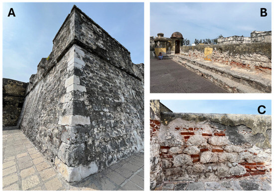
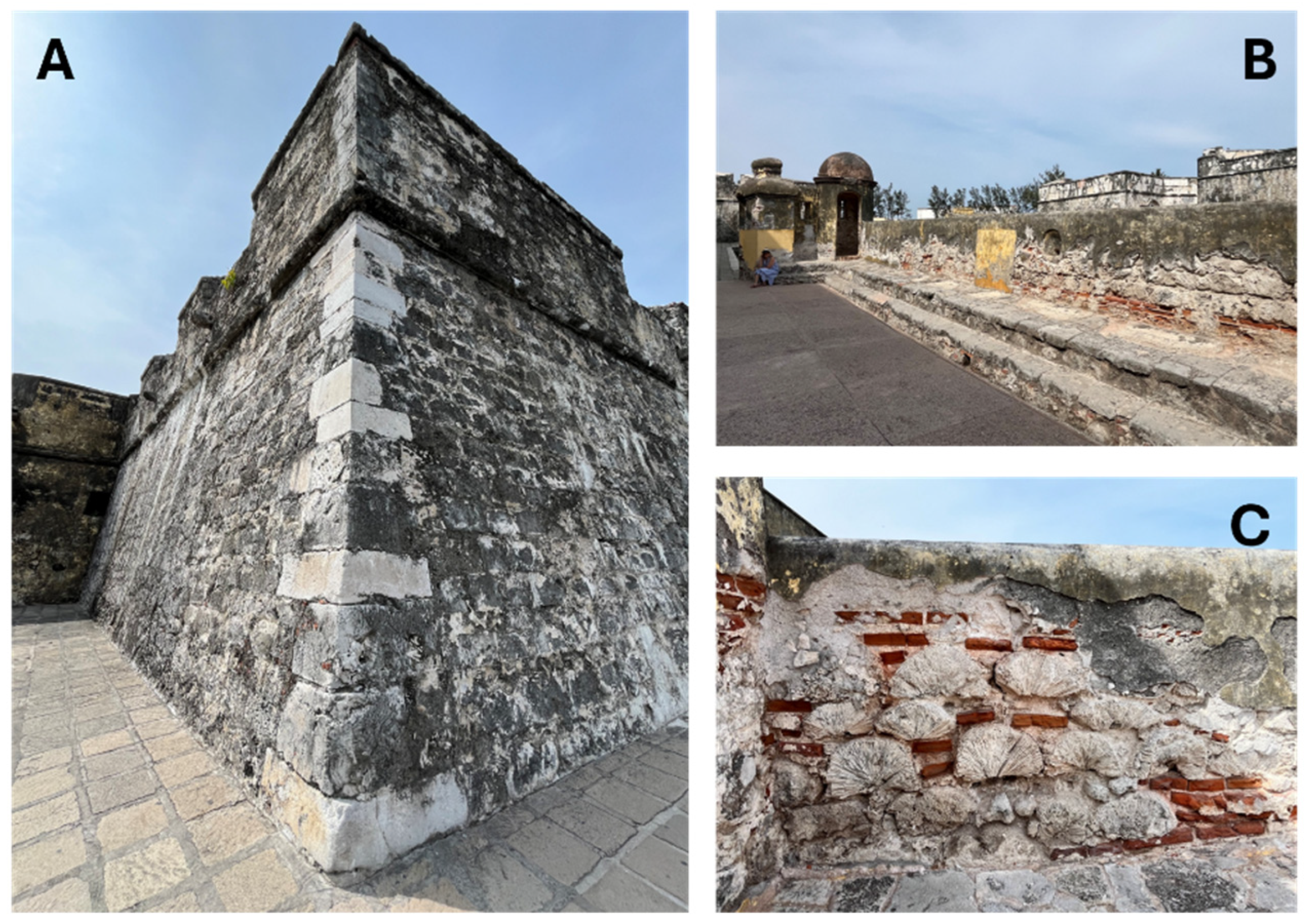
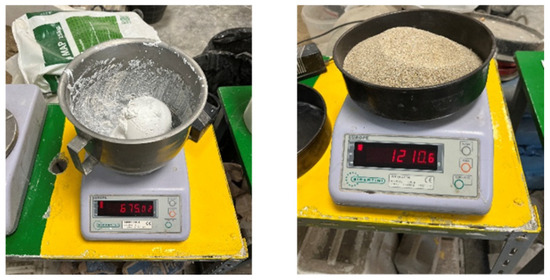
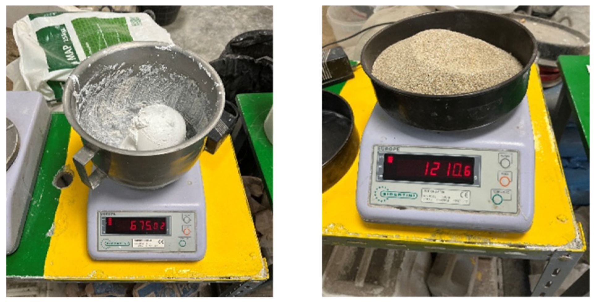
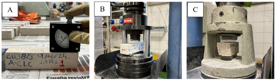
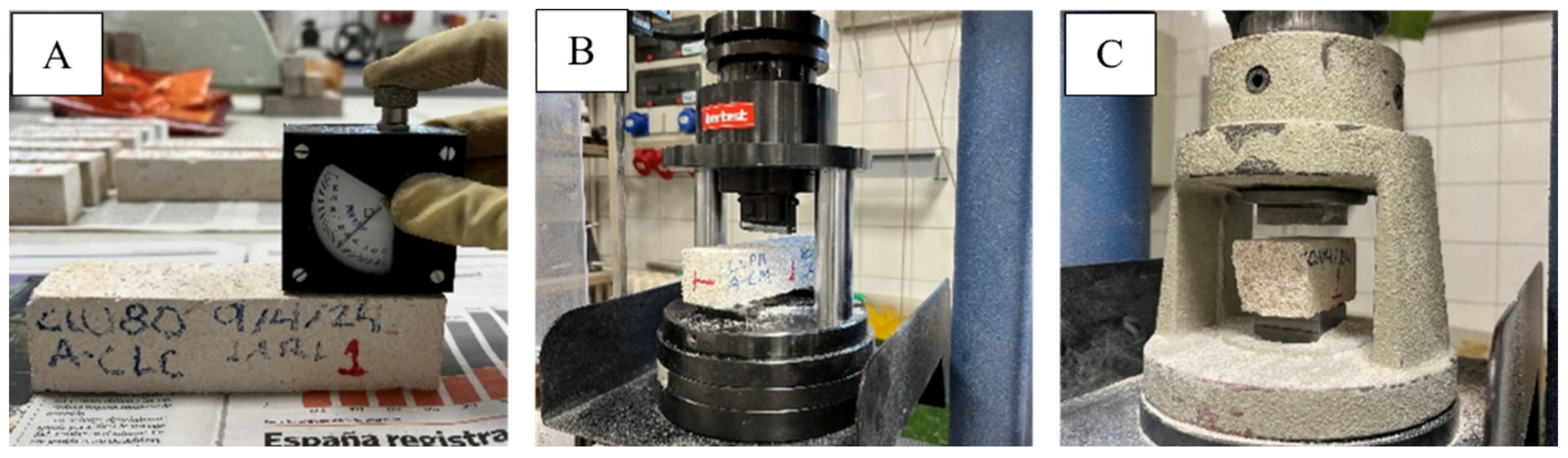
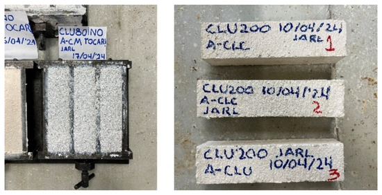
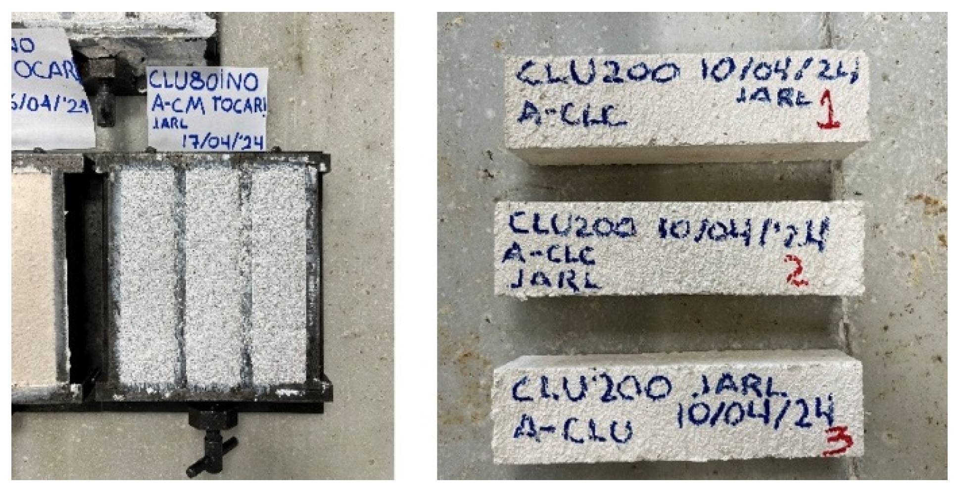
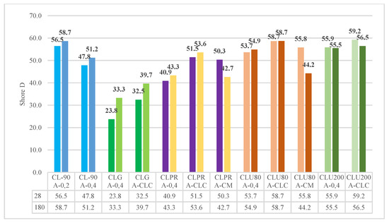
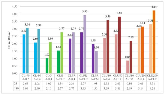
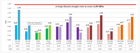
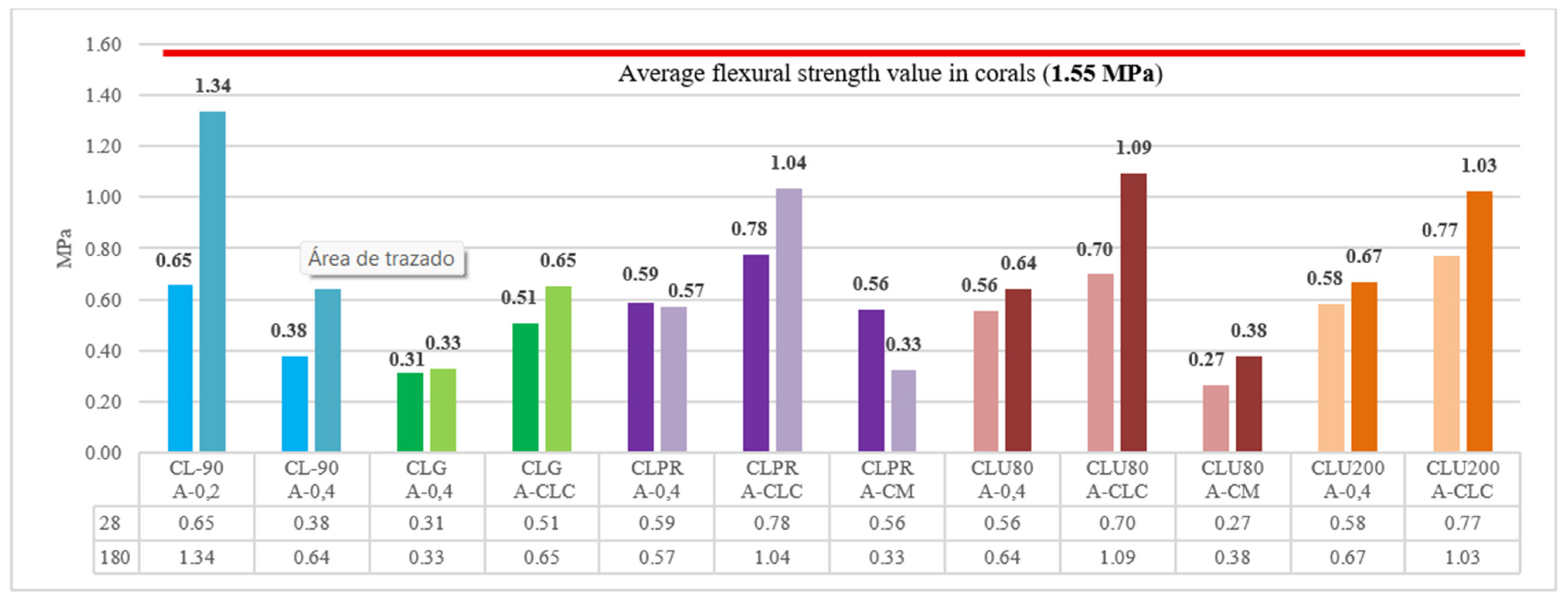
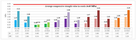
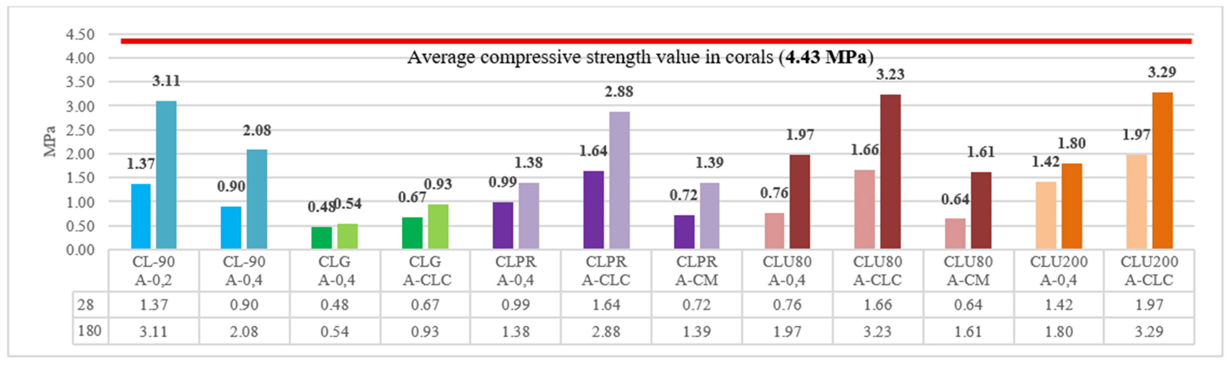
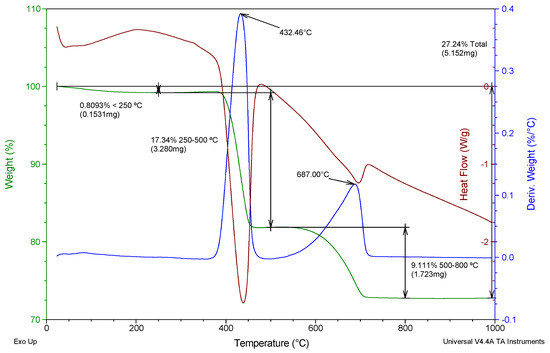
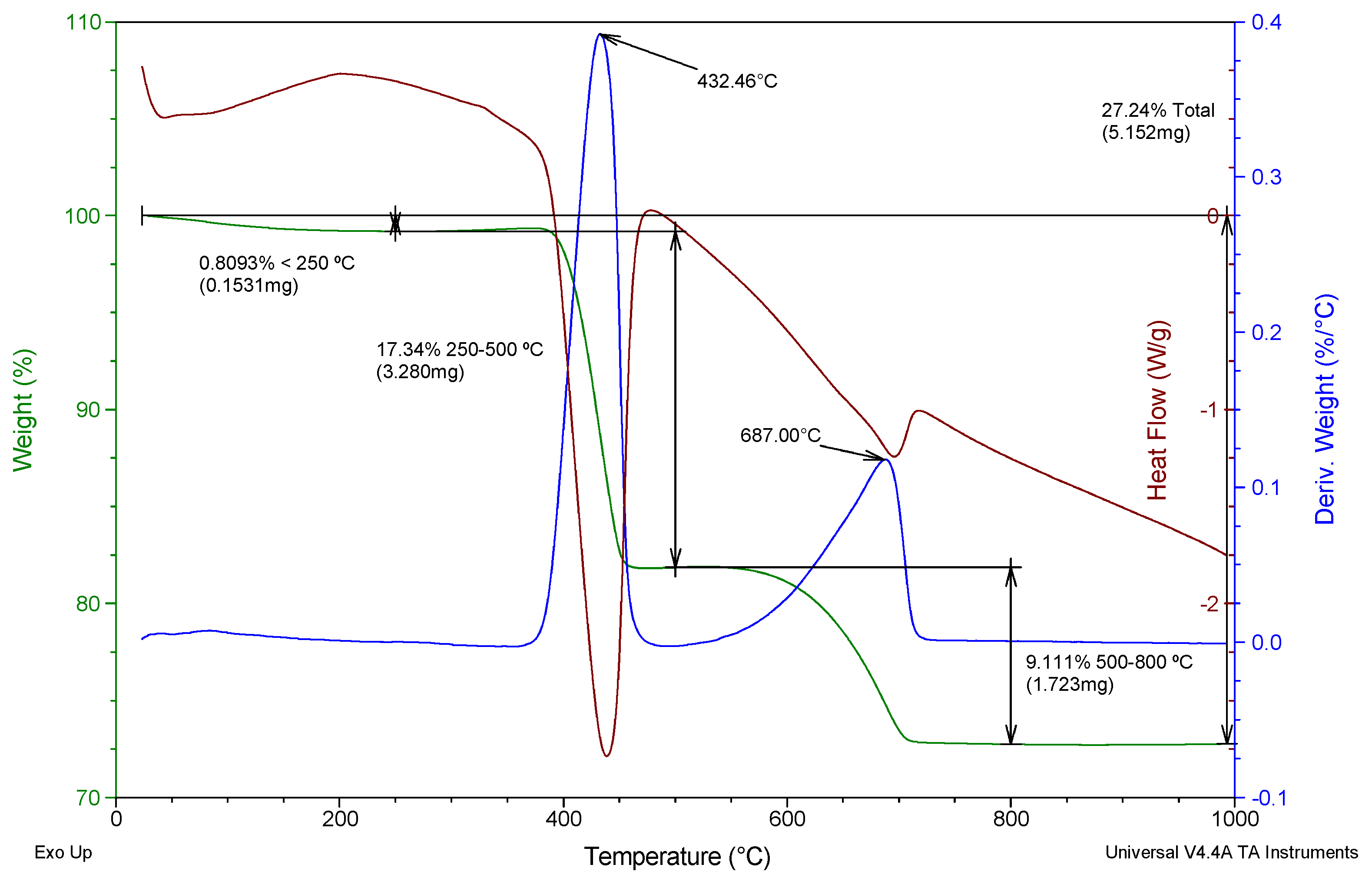
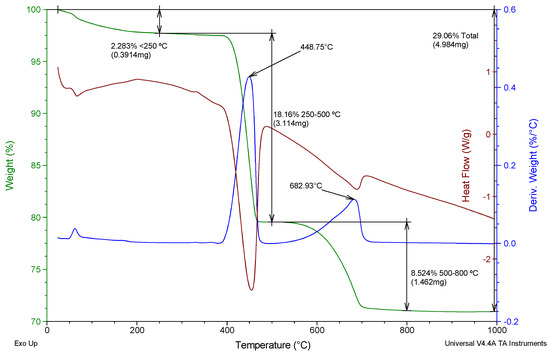
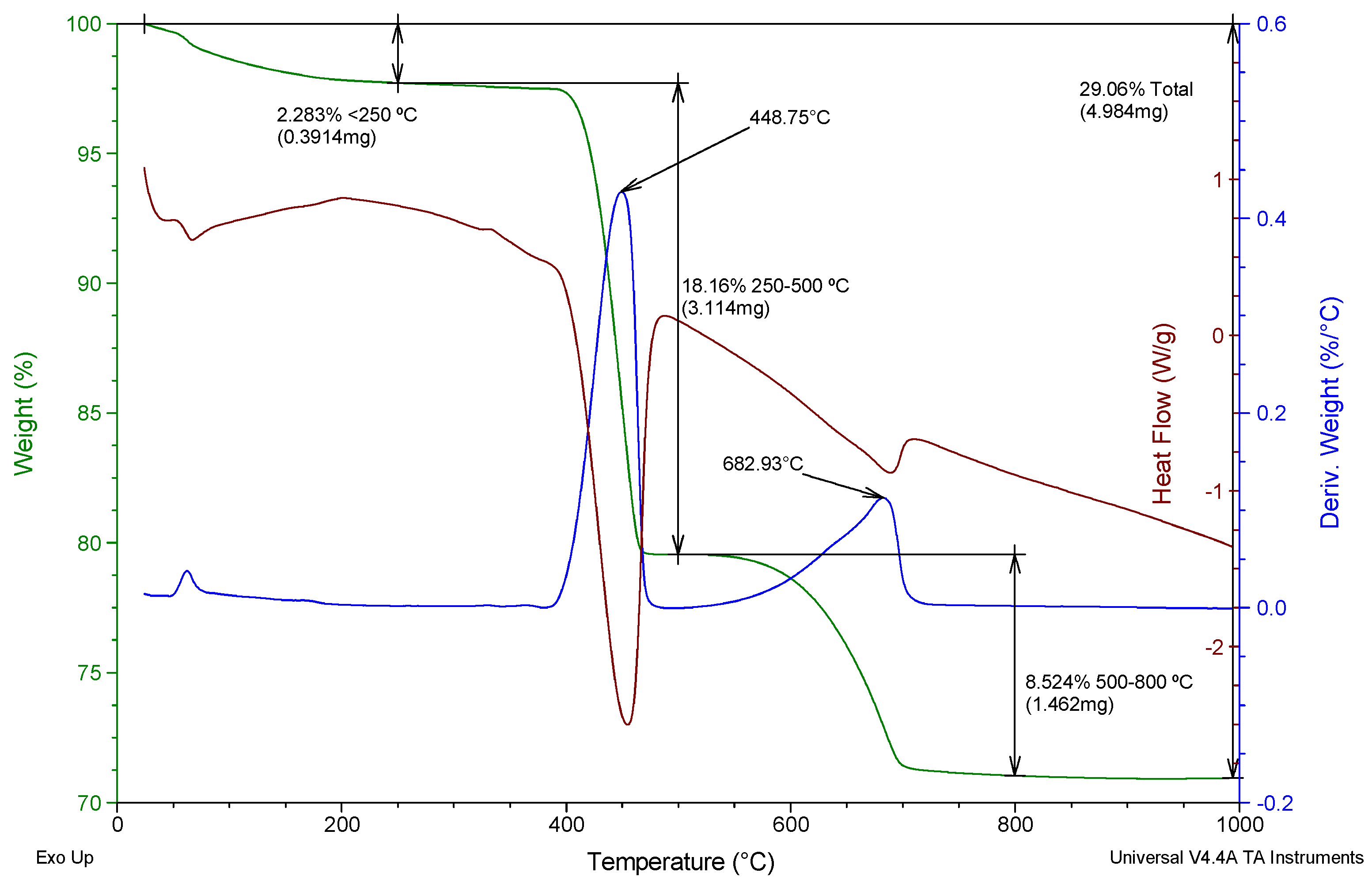
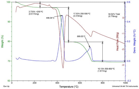
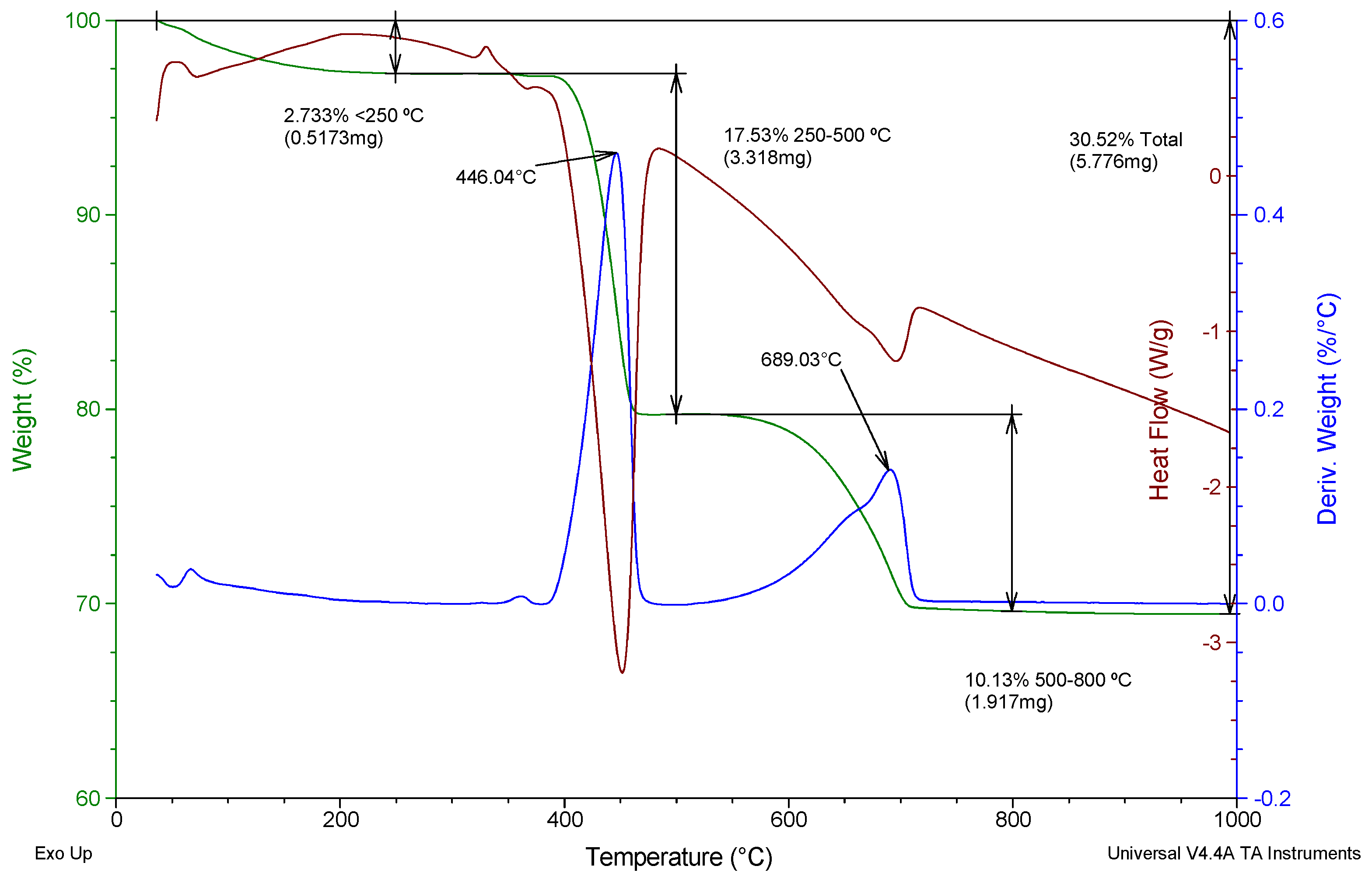
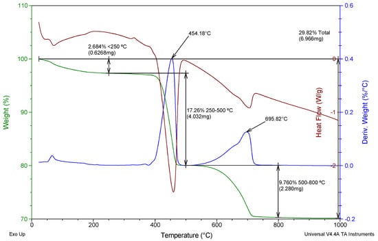
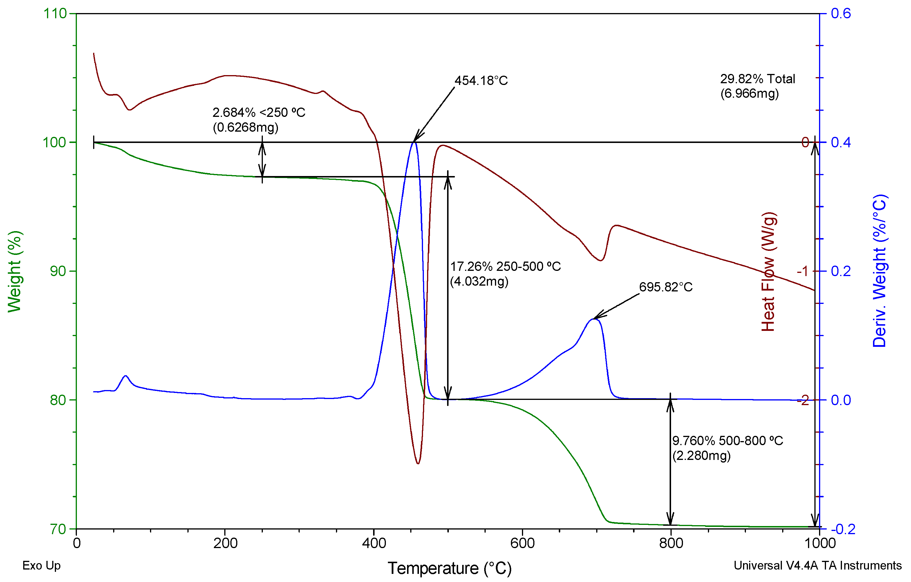
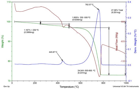
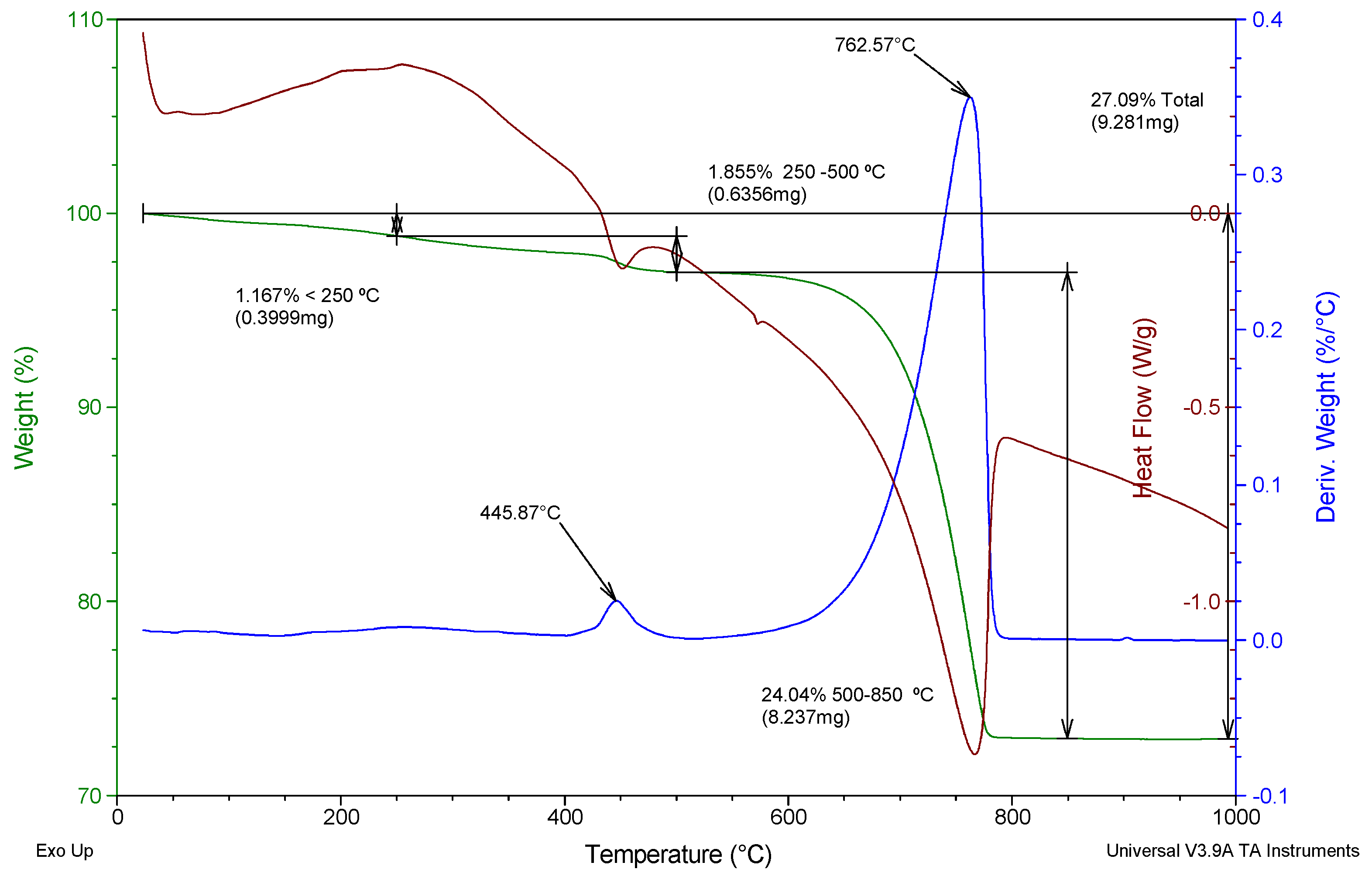
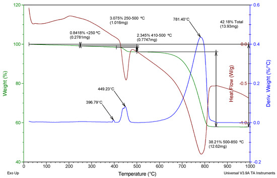
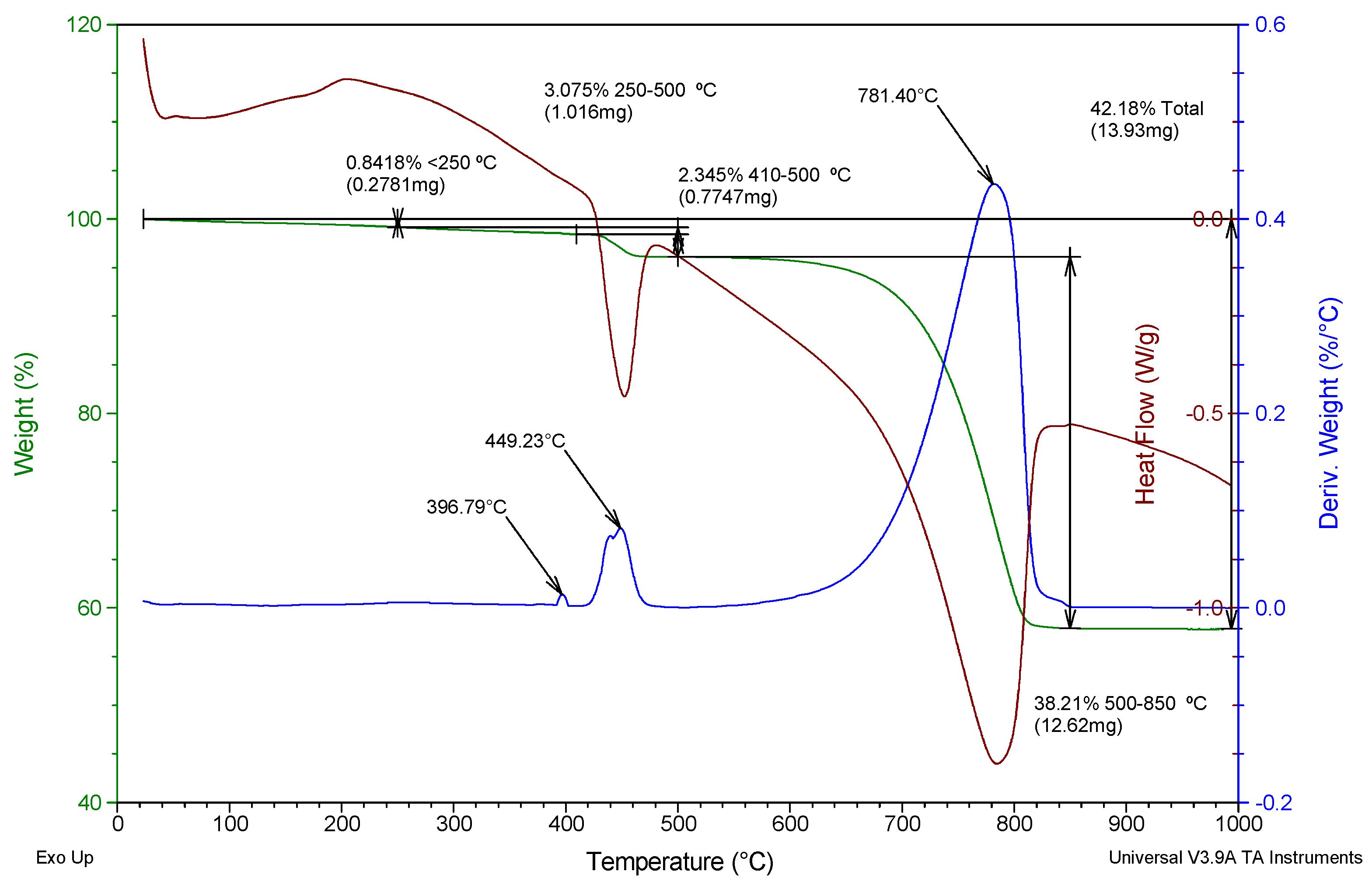
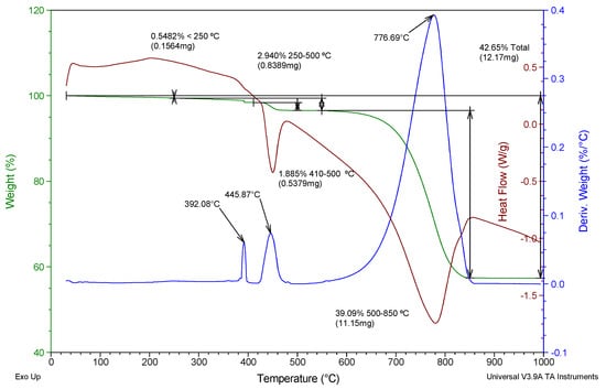
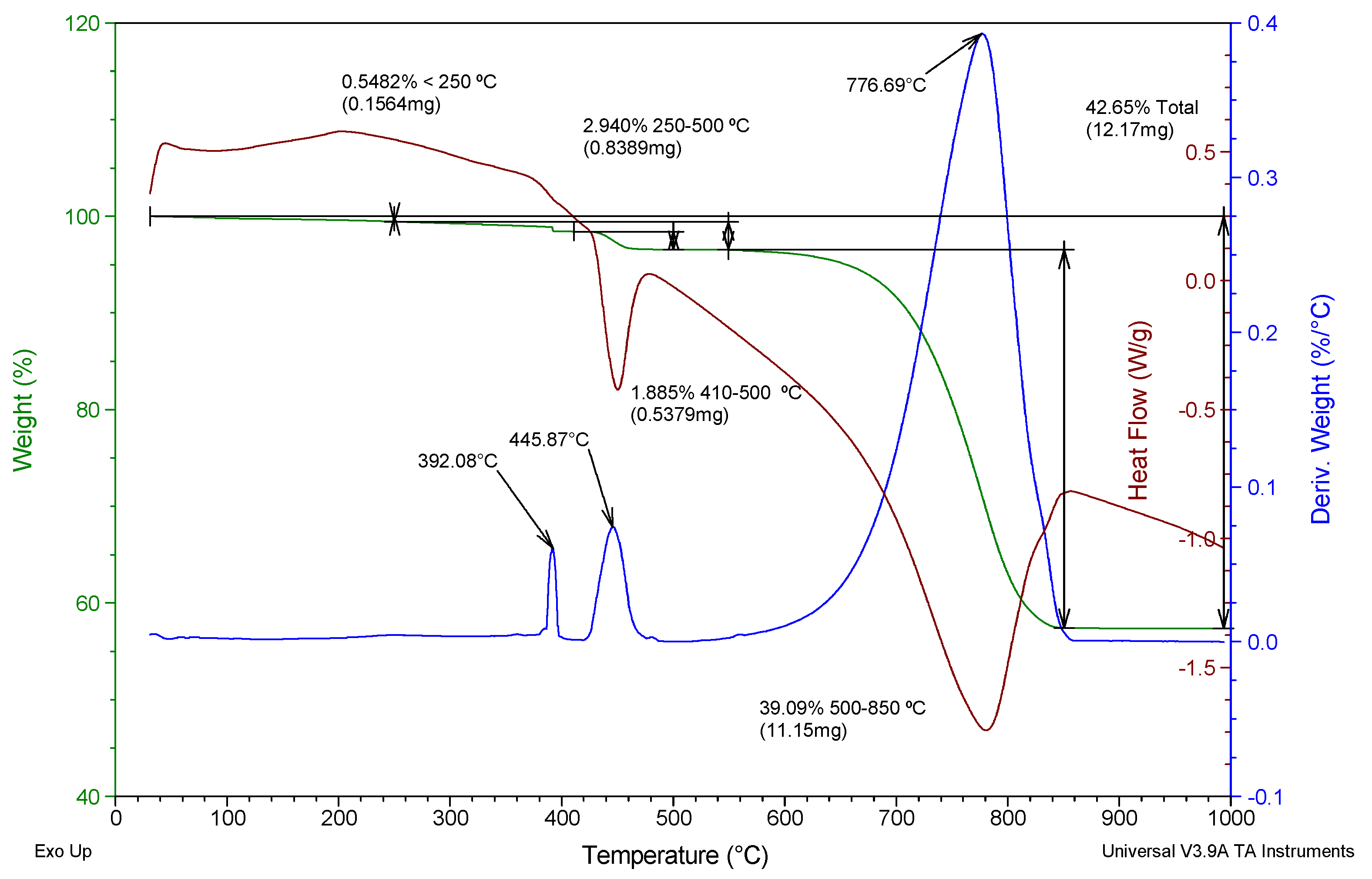
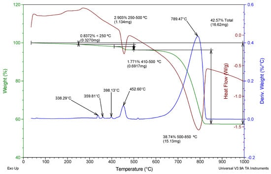
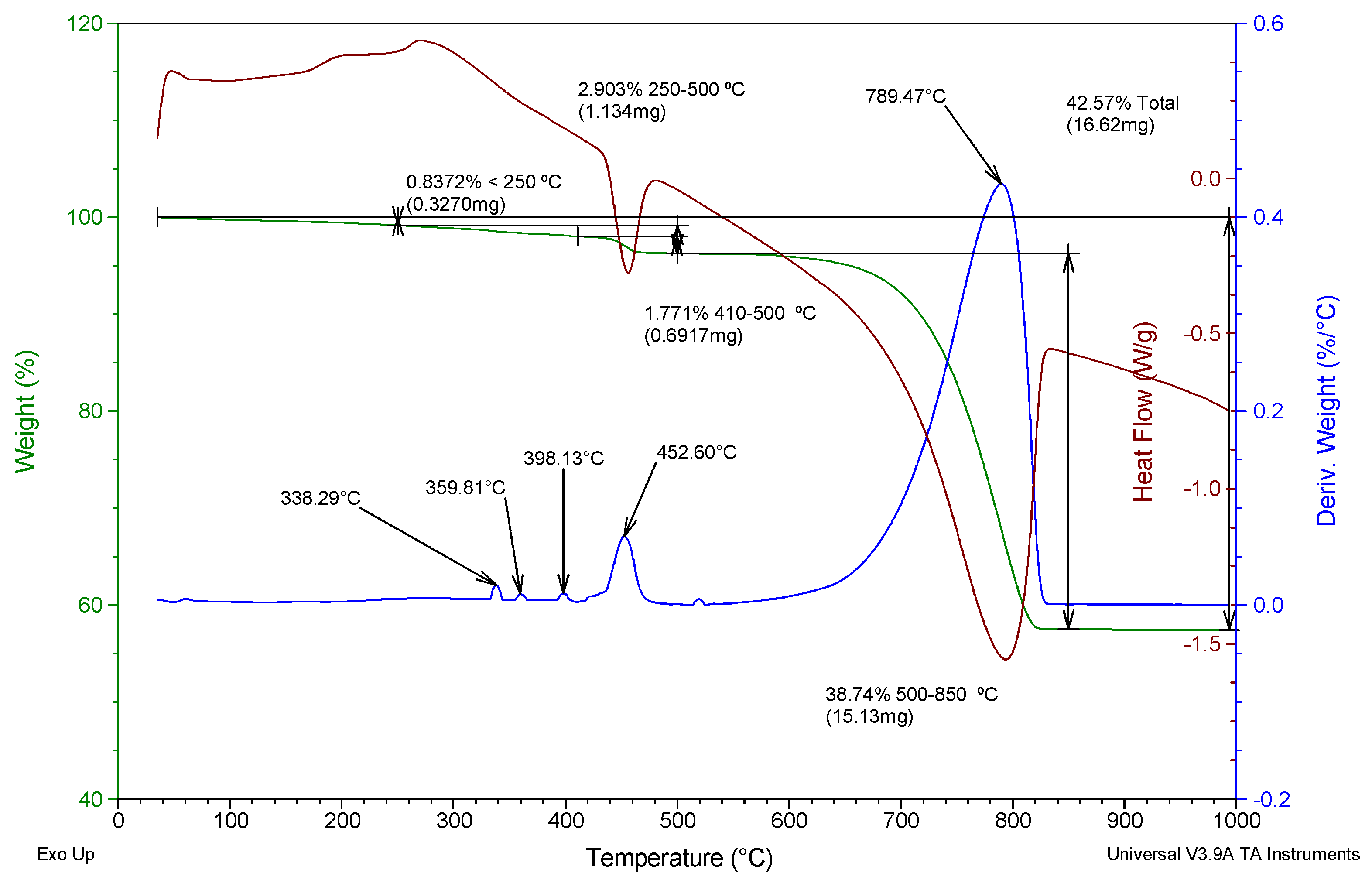
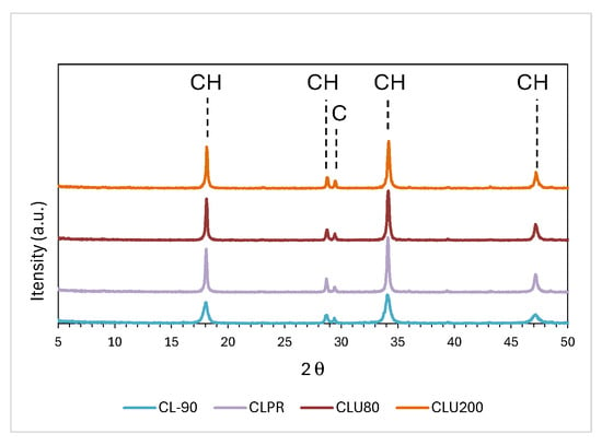
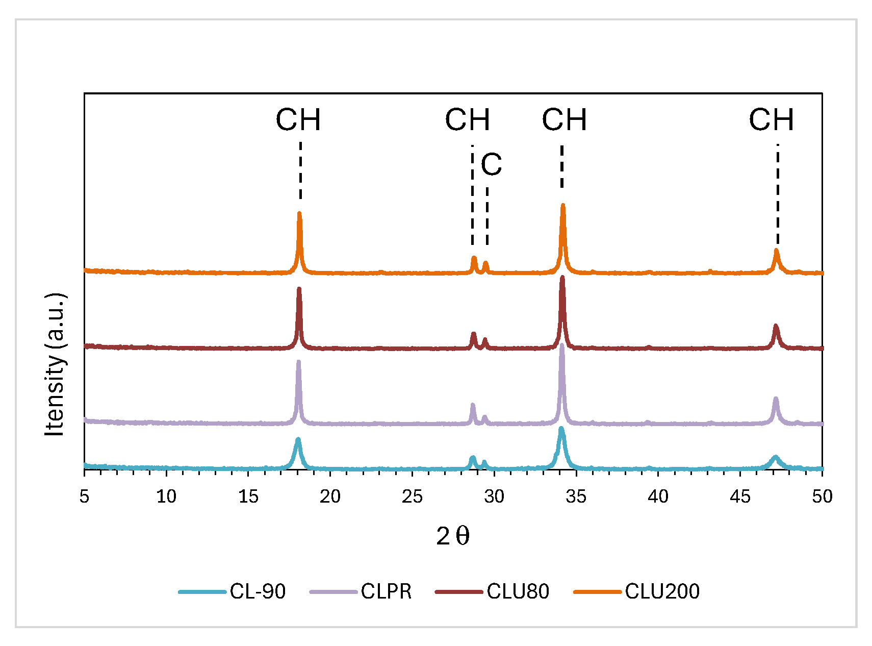
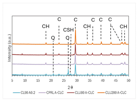
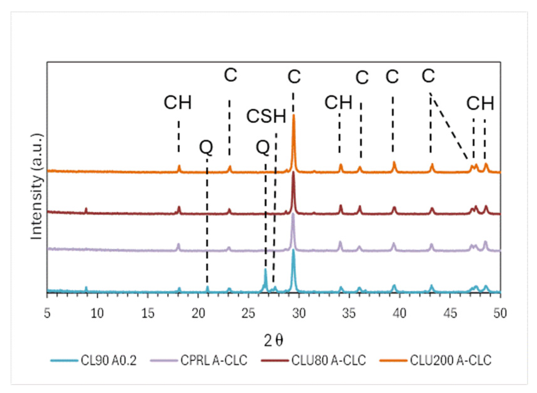
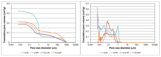
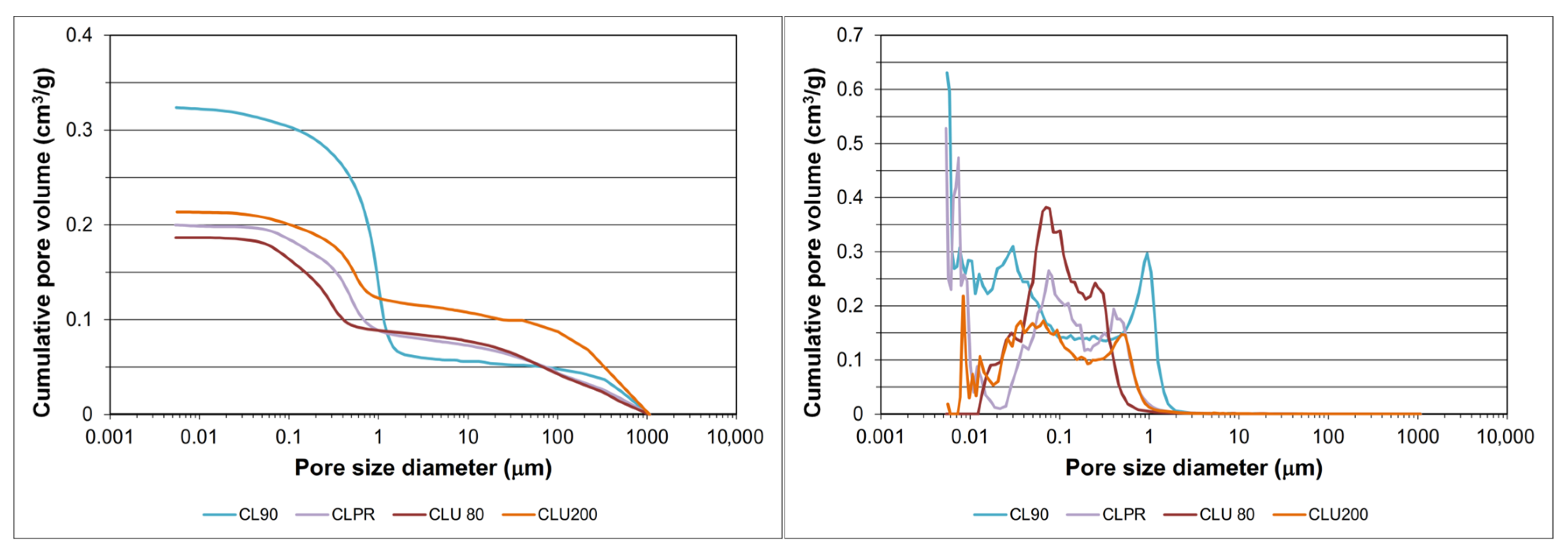

Disclaimer/Publisher’s Note: The statements, opinions and data contained in all publications are solely those of the individual author(s) and contributor(s) and not of MDPI and/or the editor(s). MDPI and/or the editor(s) disclaim responsibility for any injury to people or property resulting from any ideas, methods, instructions or products referred to in the content. |
© 2026 by the authors. Licensee MDPI, Basel, Switzerland. This article is an open access article distributed under the terms and conditions of the Creative Commons Attribution (CC BY) license.