


Abstract
Single-lane tunnels, characterized by narrow and high cross-sections with limited ventilation, present significantly higher fire hazards than conventional multi-lane tunnels. To investigate flame morphology and ceiling temperature evolution in such confined spaces, a comprehensive set of reduced-scale fire tests was conducted using a 1:10 scale tunnel model based on Froude similarity. The effects of the heat release rate (HRR), transverse fire location, and fire source height were systematically analyzed. The results indicate that the transverse fire location critically influences flame behavior: a centerline fire produces a stable, vertically symmetric flame, whereas a wall-attached fire exhibits a periodic oscillation of attachment, elongation, and detachment. The maximum ceiling temperature rise increases with both HRR and fire source height. Notably, compared to a centerline fire, a wall-attached fire can increase the maximum ceiling temperature rise by up to 39% due to sidewall confinement. Based on the experimental data, a predictive correlation for the maximum ceiling temperature rise under centerline fire conditions was established. Furthermore, a global prediction model incorporating a transverse position coefficient was proposed, which shows good agreement with the experimental results. Comparative analysis reveals that the temperature rise coefficient for the single-lane tunnel is approximately 13% higher than that of multi-lane tunnels. These findings provide a theoretical basis for fire risk assessment and safety design in single-lane tunnel infrastructure.
1. Introduction
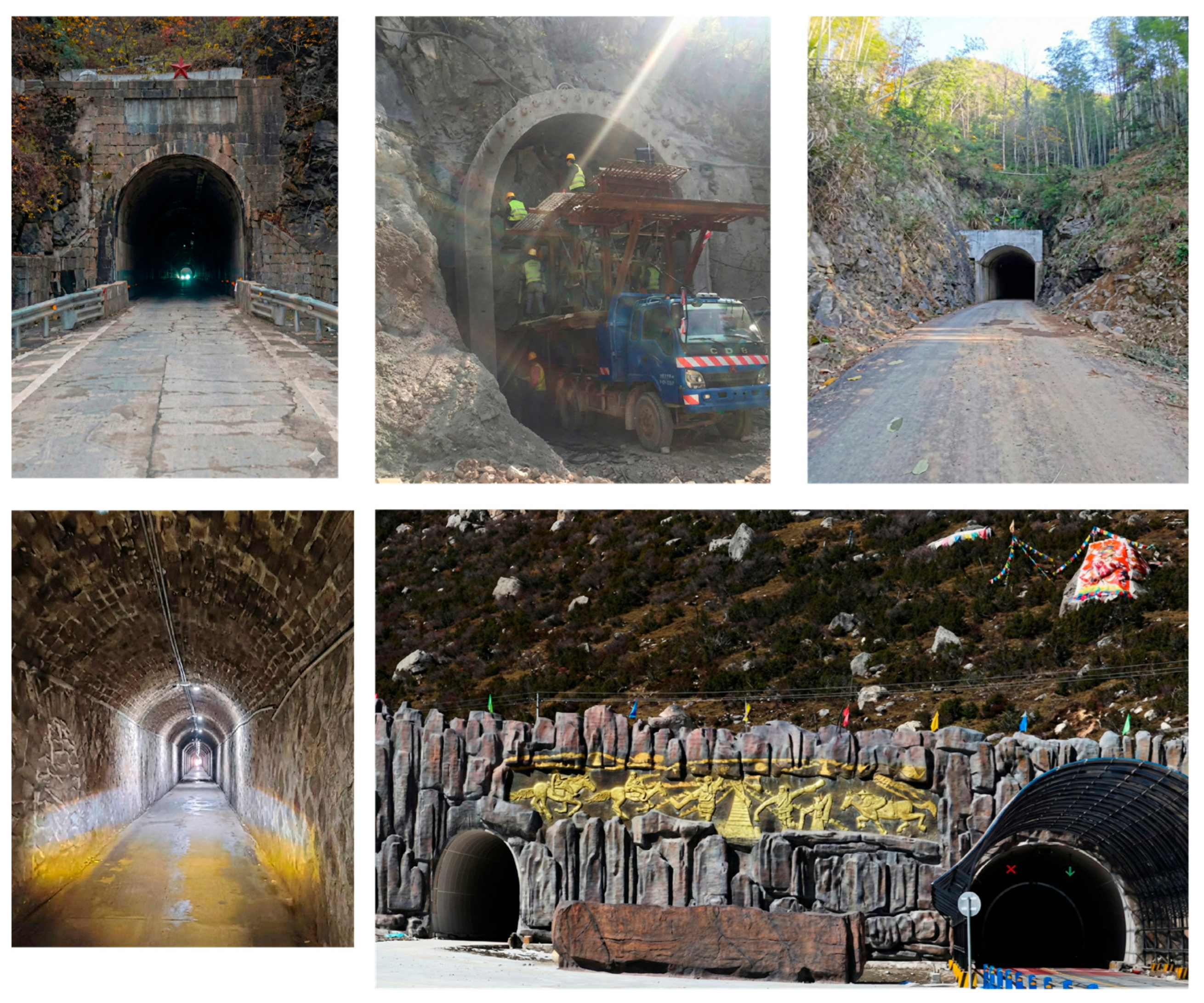
Driven by the rapid pace of urbanization and the continuous development of transportation networks in mountainous regions of China, tunnel construction has expanded rapidly [1], as tunnels can overcome topographical constraints and improve traffic efficiency [2]. As shown in Figure 1, single-lane tunnels are widely utilized in rural roads, mountain feeder routes, urban underground branches, and construction access passages, owing to their relatively low construction costs, and reduced construction complexity.
Figure 1.
Schematic of practical engineering of single-lane tunnel.
According to the Design Specification for Highway Tunnels in China (JTG 3370), single-lane tunnels are defined as tunnels with a lane width of 4.5–5.0 m, typically serving rural highways. The structural characteristics of single-lane tunnels include narrow cross-sections, large height-to-width ratios, and limited ventilation and smoke exhaust systems. Consequently, their fire risk is significantly higher than that of conventional multi-lane tunnels. The rapid accumulation of high-temperature smoke beneath the tunnel ceiling during a fire can damage the tunnel structure, potentially resulting in casualties and property losses [3,4,5].
The maximum temperature rise beneath the tunnel ceiling is a key parameter for evaluating tunnel structural safety and optimizing the layout of fire safety systems. These issues have long attracted considerable attention from both the academic community and the engineering field. In a fire, heat accumulation can significantly increase temperatures within the confined space. Tunnel structural components are vulnerable to direct exposure to hot gases and fire plumes, resulting in material degradation, reduced structural strength, and compromised protective performance [6,7,8]. Additionally, the effective performance of fire safety equipment, including smoke alarms and sprinklers, requires an accurate prediction of the peak ceiling gas temperature.
Based on standard plume theory, Equation (1) allows for the estimation of the plume centerline temperature rise at a specific vertical distance Z [9]:
where Ta is the ambient temperature, K; g is the gravitational acceleration, m/s2; ρa is the ambient density, kg/m3; cp is the specific heat capacity, J/(kg K); Z is the vertical height, m; and Q is the heat release rate, kW.
Equation (1) implicitly relies on the point source assumption. However, fires in tunnels typically involve surface sources. To resolve this discrepancy, Heskestad [10] proposed the hypothesis of a virtual origin to account for the finite size of the fire source. The vertical position of this effective source is determined by Equation (2):
where D signifies the real diameter of the fire source (m).
Regarding empirical modeling, Alpert [11] derived a predictive correlation using data from large-scale fire tests to estimate the maximum smoke temperature rise beneath the ceiling. This formula is applicable when the distance between the fire source and the sidewall is relatively large and where no significant accumulation of hot smoke occurs, as expressed in Equation (3):
where ΔTmax is the maximum smoke temperature rise beneath the ceiling, K, and H is the vertical distance from the burning surface to the ceiling, m.
Based on experiments spanning full- and reduced-scale configurations, Kurioka [12] incorporated the effect of longitudinal ventilation and developed a prediction model coupling the dimensionless heat release rate with the Froude number, as presented in Equations (4)–(6):
where is an empirical coefficient, and v is the longitudinal ventilation velocity (m/s).
Li et al. [7] identified certain limitations in Kurioka’s model. Their combined theoretical analysis and small-scale experiments demonstrated that for a dimensionless velocity (v′) below 0.19, the ceiling temperature rise becomes independent of the ventilation velocity, leading to the establishment of a segmented prediction model:
where v’ is the dimensionless velocity; r is the fire source radius (m); Hef is the effective height (m); QC is convective heat release rate of the fire (kW)
Subsequent full-scale experiments further confirmed that the maximum temperature beneath the tunnel ceiling during a fire can reach up to 1350 °C [8], providing important experimental evidence for structural fire protection design.
Building on the aforementioned studies, researchers have further investigated the influence of various factors on ceiling temperature development, including the transverse location of the fire source [13,14,15], longitudinal fire position [16,17,18], tunnel blockage conditions [19,20], longitudinal ventilation [7,21], tunnel slope [22,23,24,25,26,27], bifurcation angle [28,29,30], precipitation intensity [31,32], and multi-fire source scenarios [33,34]. These studies have established a range of predictive models that provide valuable guidance for ceiling temperature estimation under specific fire scenarios.
Although the maximum temperature rise beneath the tunnel ceiling has been extensively studied for parameters including tunnel slope, blockage, branch angle, and ventilation, most existing research has primarily focused on multi-lane tunnels. This includes full-scale experimental programs such as EUREKA EU499 [35] and the Memorial Tunnel Fire Ventilation Test Program [36,37], as well as reduced-scale experiments conducted by Fan [38], Gao [39], and Ji [16]. However, the distinct characteristics of single-lane tunnels have not yet been fully addressed.
Single-lane tunnel has risk characteristics significantly different from those of multi-lane tunnels. First, the tunnel cross-section is narrow, providing limited lateral clearance for vehicles, following a fire, evacuation and rescue routes can easily become congested. Second, the “narrow and high” cross-sectional geometry—with a clearance height of 4.5–5.0 m according to the Code for Design of Urban Road Engineering (CJJ37-2012)—intensifies heat accumulation, resulting in a rapid rise in ceiling temperature. Third, single-lane tunnels are widely deployed in mountainous regions and as temporary construction access roads, potential fire sources include small vehicles, construction machinery, and agricultural equipment, the fire source height can vary significantly, leading to differences in flame behavior and temperature rise. Finally, traffic accidents may cause vehicles to collide with tunnel sidewalls, resulting in fires occurring at any transverse locations within the tunnel cross-section.
To address this gap, the present study investigates fire dynamics within single-lane tunnels and aims to investigate flame morphology and the maximum ceiling temperature rise by experiments. The study also seeks to provide a support for fire protection in the single-lane tunnels.
2. Materials and Methods
2.1. Experimental Set-Up
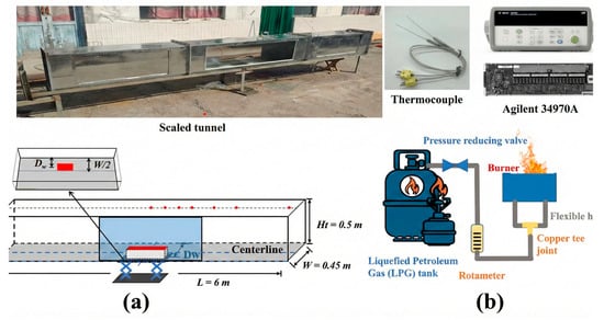
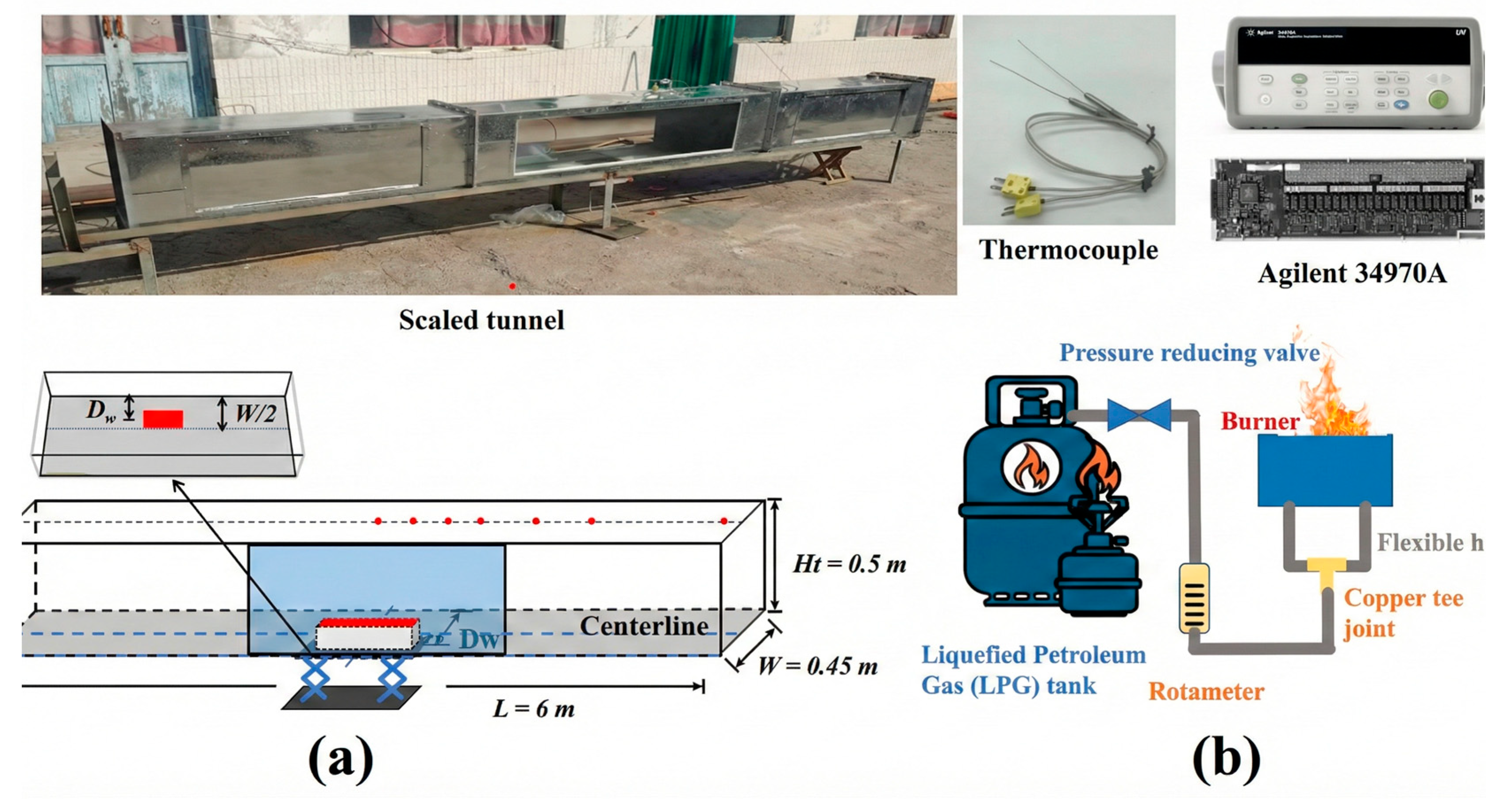
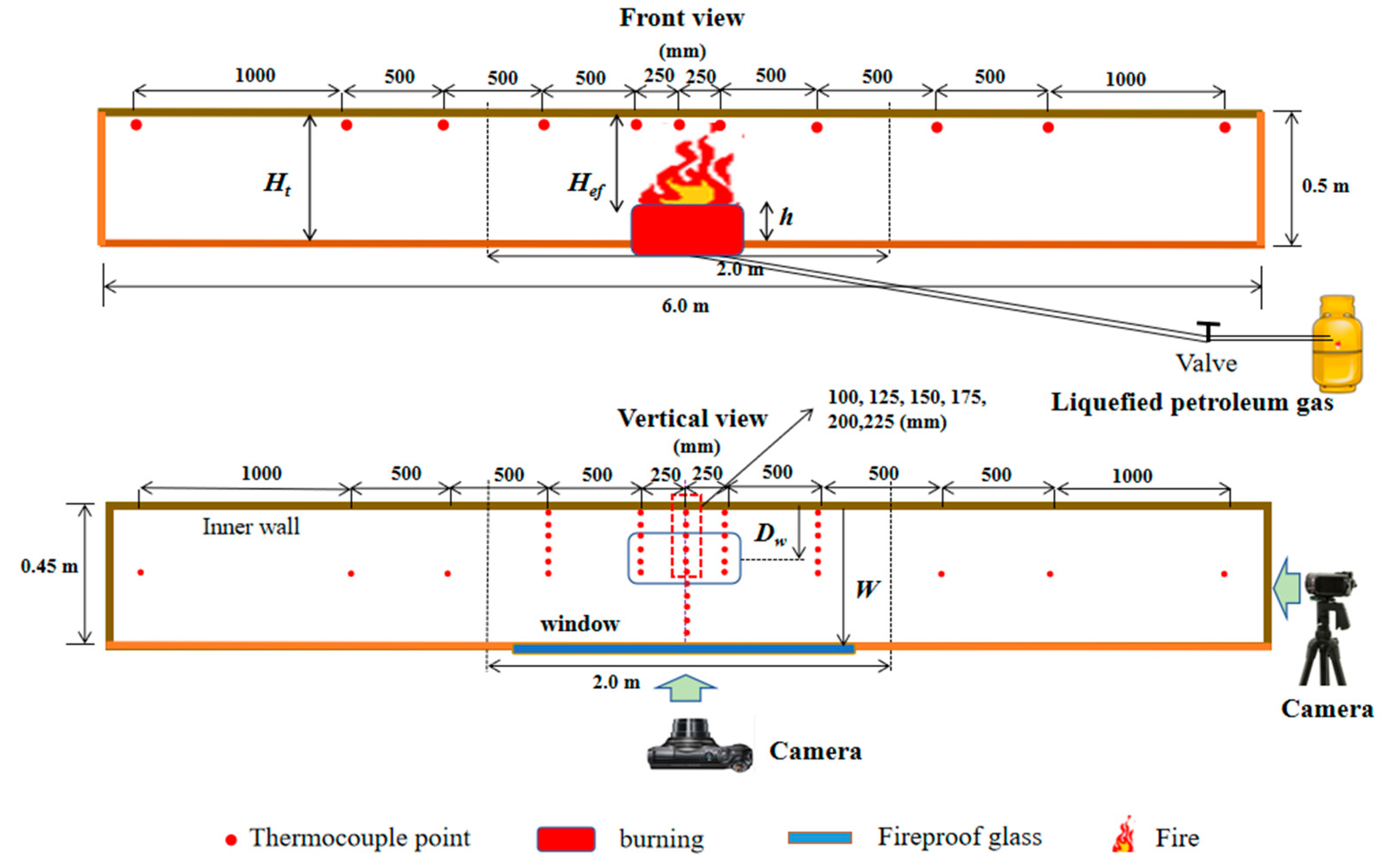
The experimental program utilized a 1:10 geometrically scaled tunnel model designed according to the Froude similarity [40]. The scaling relationships for the physical quantities are summarized in Table 1. As shown in Figure 2a, the model tunnel had a total length of 6.0 m and a rectangular cross-section of 0.45 m (width) × 0.5 m (height), representing a single-lane tunnel.
Table 1.
Froude similarity criterion number.
Figure 2.
Experimental setup: (a) Experimental model; (b) Fire source system.
The tunnel model was fabricated from 1.5 mm thick galvanized steel plates. To prevent thermal deformation, a 5 mm thick layer of fire-resistant gypsum board was applied to the interior surface of the tunnel ceiling. To observe flame behavior, a 3 mm thick fireproof glass window was installed along one side of the tunnel. Holes with a diameter of 3 mm were drilled into the ceiling and sidewalls for sensor installation.
The fire source consisted of a rectangular burner measuring 30 cm × 20 cm, filled with pebbles to ensure uniform flame distribution. These dimensions were selected based on a 1:10 geometric scaling of a typical passenger car (approximately 3.0 m × 2.0 m), which represents the primary fire hazard in single-lane tunnels. The burner was fueled by liquefied petroleum gas (LPG). The gas flow rate, regulated via a rotameter (Figure 2b), determined the heat release rate (HRR). Consistent with prior research [41,42], the corresponding full-scale HRR was set between 2 and 5 MW. According to Froude scaling, this corresponds to a model HRR range of 6.32–15.8 kW, as summarized in Table 2. The HRR was calculated using Equation (8):
where is the combustion efficiency; v is the gas flow rate; is the effective heat of combustion of LPG, taken as 51.747 kJ/L [43].
Table 2.
Scale model experimental fire power comparison table.
2.2. Instrumentation and Measurement
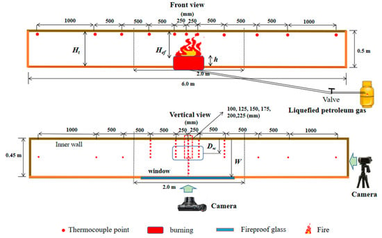
The experiment mainly measures temperature and flame morphology. Temperature was measured using K-type armored thermocouples with a diameter of 1.0 mm and an accuracy of ±0.5 °C. The thermocouples were positioned 1 cm below the ceiling surface to characterize the temperature distribution beneath the ceiling.
As shown in Figure 3, six rows of thermocouples were arranged transversely at distances of 100, 125, 150, 175, 200, and 225 mm from the sidewall. Three lines of thermocouples were positioned parallel to the tunnel centerline on one side at intervals of 250 mm. An Agilent 34970A data acquisition system was employed to acquire all temperature data, the maximum temperature rise was determined by selecting the peak value recorded by the thermocouple located directly above the fire source.
Figure 3.
Schematic diagram of thermocouple distribution.
Flame morphology was recorded using two Sony digital cameras (Sony, Tokyo, Japan). One camera was positioned at the tunnel entrance to observe the frontal flame profile, and another was placed on the side to capture the longitudinal flame evolution.
2.3. Experimental Procedure and Conditions
A systematic study of the coupled effects of the heat release rate (HRR) and fire source position was undertaken. The experimental cases are shown in Table 3, which comprises four HRR levels, six transverse fire locations (Dw), and three fire source heights (h).
Table 3.
Summary of experimental conditions.
The experiments followed a standardized procedure. First, the data acquisition system was activated to record ambient conditions. Subsequently, the fire was ignited, and the gas flow rate was adjusted to the target level. The fire was maintained for a duration of 500 s to ensure a quasi-steady state was reached. Upon completion, the gas supply was shut off, and data recording ceased. Between tests, the tunnel was ventilated to restore the initial ambient temperature. To ensure data reliability, each experimental condition was repeated three times, and the standard deviation of the measured temperature was found to be within 5%.
3. Results and Discussion
3.1. Flame Behavior
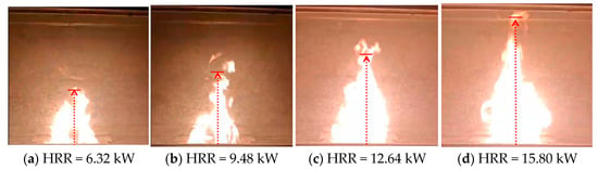
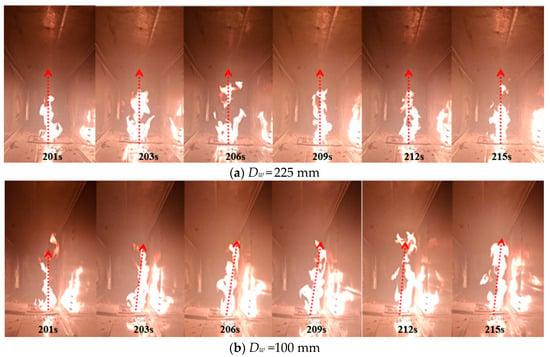
Figure 4 illustrates the stabilized flame shapes at different HRRs when the fire was located on the tunnel centerline. As shown in Figure 4, flames from the rectangular fire source develop a distinct triangular morphology. A progressive increase in flame length was observed as the HRR rises. At low HRRs, the flame remained within the tunnel without impinging on the ceiling. However, once the HRR reached 15.80 kW, the flame intermittently impinged on the ceiling.
Figure 4.
Flame behavior under different HRRs on the centerline.
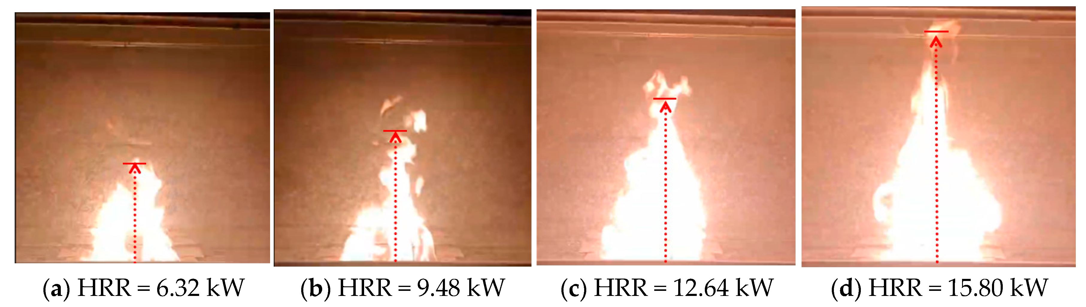
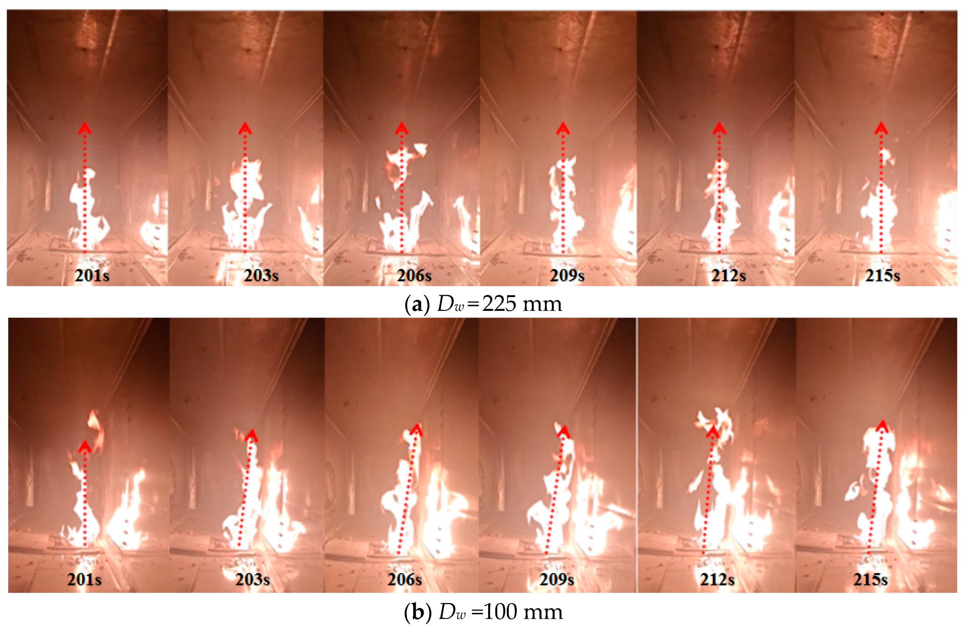
Figure 5 shows the variations in flame behavior at different transverse fire locations. When the HRR was 15.80 kW and the fire source was positioned at the tunnel centerline (Dw = 225 mm), the flame was vertical and stable. The height of the fire fluctuated up and down, occasionally impinging on the ceiling, while the edges of the flame maintained an equal distance from both sidewalls.
Figure 5.
Flame behavior with different transverse positions.
The reason for this is that with the fire source at the tunnel centerline, the air entrainment surrounding the flame exhibits symmetry, as the flame can entrain air from both sides. The entrainment of air from both sides is equal, resulting in equal air momentum on both sides, causing the flame to exhibit a vertical and symmetrical shape.
When the fire source was adjacent to the tunnel sidewall, the flame morphology exhibited periodic variations. During the initial combustion stage, the flame developed vertically, similar to the early-stage behavior observed for a centrally located fire. As the fire progressed, the flame inclined toward the sidewall and eventually became fully attached to it. In this wall-attached state, the flame width was significantly reduced, while the flame height increased markedly and extended to the tunnel ceiling, forming a narrow and elongated wall-attached flame. After a short period of sustained wall-attached burning, the flame suddenly detached from the sidewall and rebounded toward the tunnel center, flame height decreased while its lateral width temporarily increased, returning to a vertical flame shape. Subsequently, the flame inclined again toward the sidewall and reattached, resulting in repeated periodic cycles.
The observed phenomenon is attributed to the sidewall constraint, which causes different air entrainment on both sides of the flame. When the fire source is adjacent to the sidewall, air entrainment on the wall side is strongly suppressed by the boundary, and the flame is mainly sustained by entrainment from the central side. This single-sided entrainment promotes flame attachment and vertical elongation along the sidewall. As wall-attached burning persists, the temperature in the sidewall region increases significantly. This leads to a reduction in local gas density, further weakening the entrainment capability on the wall side and decreasing the stability of the wall-attached flame configuration. Once the total amount of air entrained from one side is insufficient to sustain the flame, it expands toward the central area to entrain more air, presenting with the flame tip bouncing off the sidewall, while the middle part of the flame detaches from the wall, entering a brief vertical state. However, owing to asymmetric air entrainment, the flame tilts back toward the sidewall, resulting in periodic oscillations.
3.2. Maximum Smoke Temperature Rise for a Centerline Fire
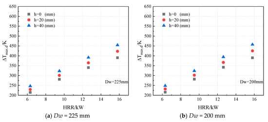
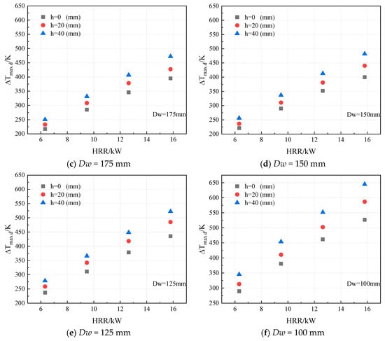
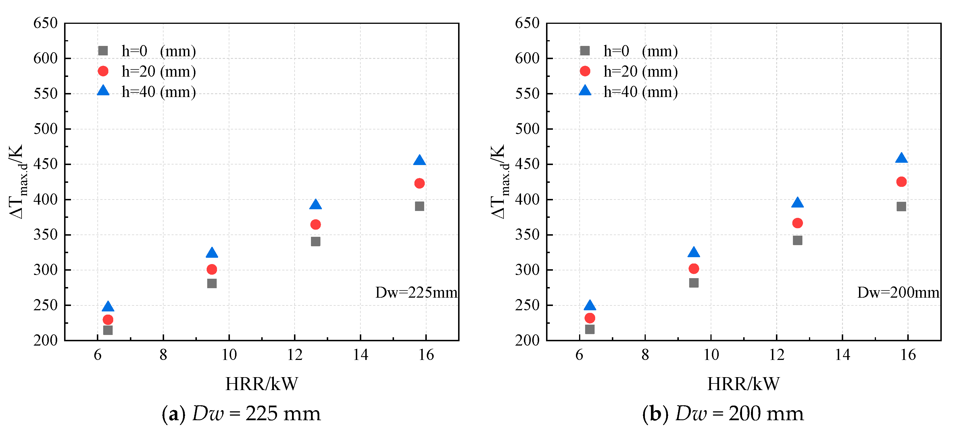
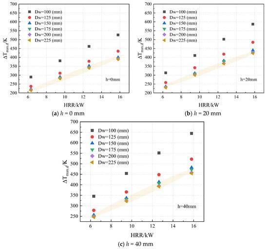
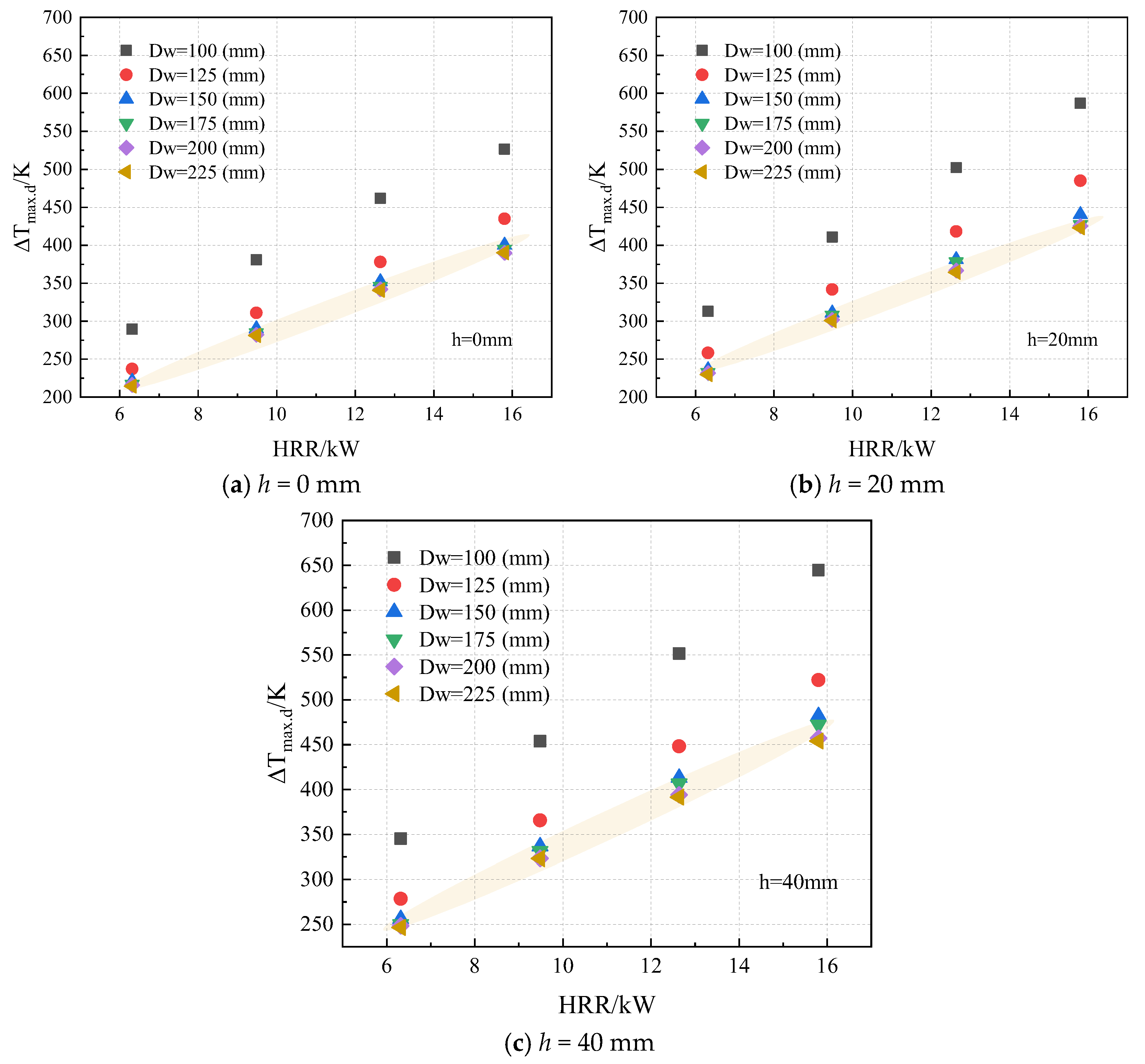
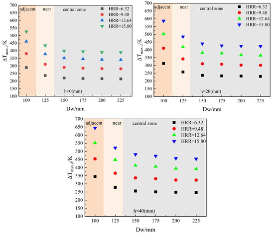
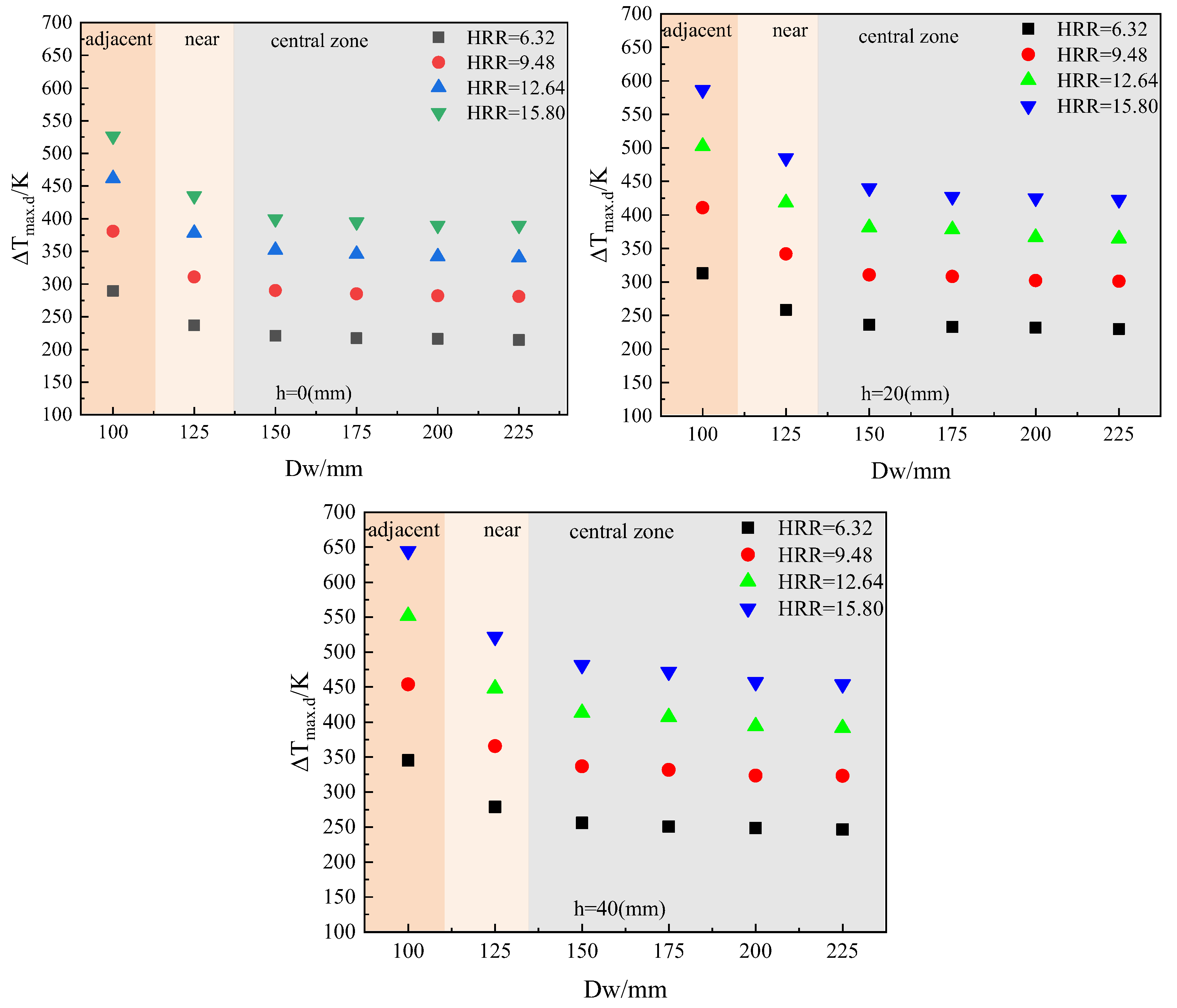
Figure 6 presents the maximum ceiling temperature rise as a function of HRR and fire source height across different transverse fire locations. The results indicate a positive correlation between the fire source height and the ceiling temperature rise.
Figure 6.
Variation in ceiling maximum temperature rise with HRR and h.
As shown in Figure 6a, for a 6.32 kW fire, the maximum ceiling temperature rise reached approximately 214, 229, and 246 K at fire source heights of 0, 20, and 40 mm, respectively, corresponding to a maximum increase of about 15%. This behavior is attributed to the reduction in the vertical separation between the fire source and the tunnel ceiling as the fire source is elevated above the ground, which enhances the heat flux impinging on the ceiling from the fire plume [44].
Although the relative increase in the maximum temperature rise observed in this study is moderate, this can be attributed to the limited range of fire heights considered. It is reasonably anticipated that a further elevation of the fire source—such as in fires involving large or high vehicles—would result in a substantially more severe thermal environment beneath the ceiling [45].
Furthermore, for a fixed fire source height, HRR emerged as the dominant factor influencing the ceiling temperature rise. Higher HRRs resulted in significantly greater temperature rises, particularly with an elevated fire source. Specifically, for a fire source height of 40 mm, increasing the HRR from 6.32 kW to 15.8 kW caused the ceiling temperature rise to increase from 246 K to approximately 454 K, representing an absolute increase of 208 K. This corresponds to an approximately 85% increase in the maximum ceiling temperature rise for a 9.48 kW increment in HRR, demonstrating that HRR plays a governing role in the ceiling thermal response within confined tunnel fire scenarios [46].
Figure 7 illustrates the variation in the maximum ceiling temperature rise with the fire heat release rate and the transverse distance between the fire source and the sidewall under different fire source heights. Taking the case with a fire source height of h = 20 mm and a HRR of 12.64 kW as an example, a pronounced influence of the transverse fire location on the ceiling thermal response is clearly observed.
Figure 7.
Ceiling maximum temperature rise with HRR and transverse fire source.
Figure 6 and Figure 7 both illustrate the effect of the HRR on the maximum ceiling temperature rise. The experimental data indicate that the maximum ceiling temperature increased markedly with increasing HRR, and this trend remained consistent across different fire locations. In addition, the ceiling temperature rise increased significantly with increasing fire source height, indicating that HRR and fire source height are the two dominant parameters governing the ceiling thermal response.
By contrast, the effect of the transverse fire location on the ceiling temperature became significant only when the fire is located in the wall-adjacent region. Once the fire source was sufficiently close to the tunnel center, variations in transverse distance had a relatively weak effect on the maximum ceiling temperature rise. Based on the above experimental observations, and with reference to previous studies on tunnel fires (which considered fires located along the tunnel centerline as the primary research focus) [7,8,18], the present study first analyzed experimental data obtained from the tunnel centerline region for analysis. This approach enabled the general relationship between ceiling temperature rise, heat release rate, and fire source height to be examined while minimizing the influence of special boundary conditions. It also highlighted the dominant role of the governing variables and provided a sound basis for subsequently introducing a correction factor associated with sidewall distance, thereby allowing the development of a ceiling temperature rise prediction model applicable over the entire tunnel cross-section.
In previous investigations of maximum ceiling temperature rise in elongated or confined spaces, a series of empirical correlations were proposed by Alpert [11], Li [7,8], and Yao [18]. Building on these previous correlations, the present study establishes a predictive expression for the maximum ceiling temperature rise for a centrally located fire under natural ventilation conditions. Accordingly, the maximum ceiling temperature rise induced by a tunnel fire is assumed to satisfy the following functional relationship:
where Q is heat release rate of the fire (kW), and Hef is the effective height (m).
Equation (9) was derived using the experimental data obtained from the scaled model tests, such that it adequately captures the effects of the HRR and fire source height on the maximum ceiling temperature rise in a single-lane tunnel.
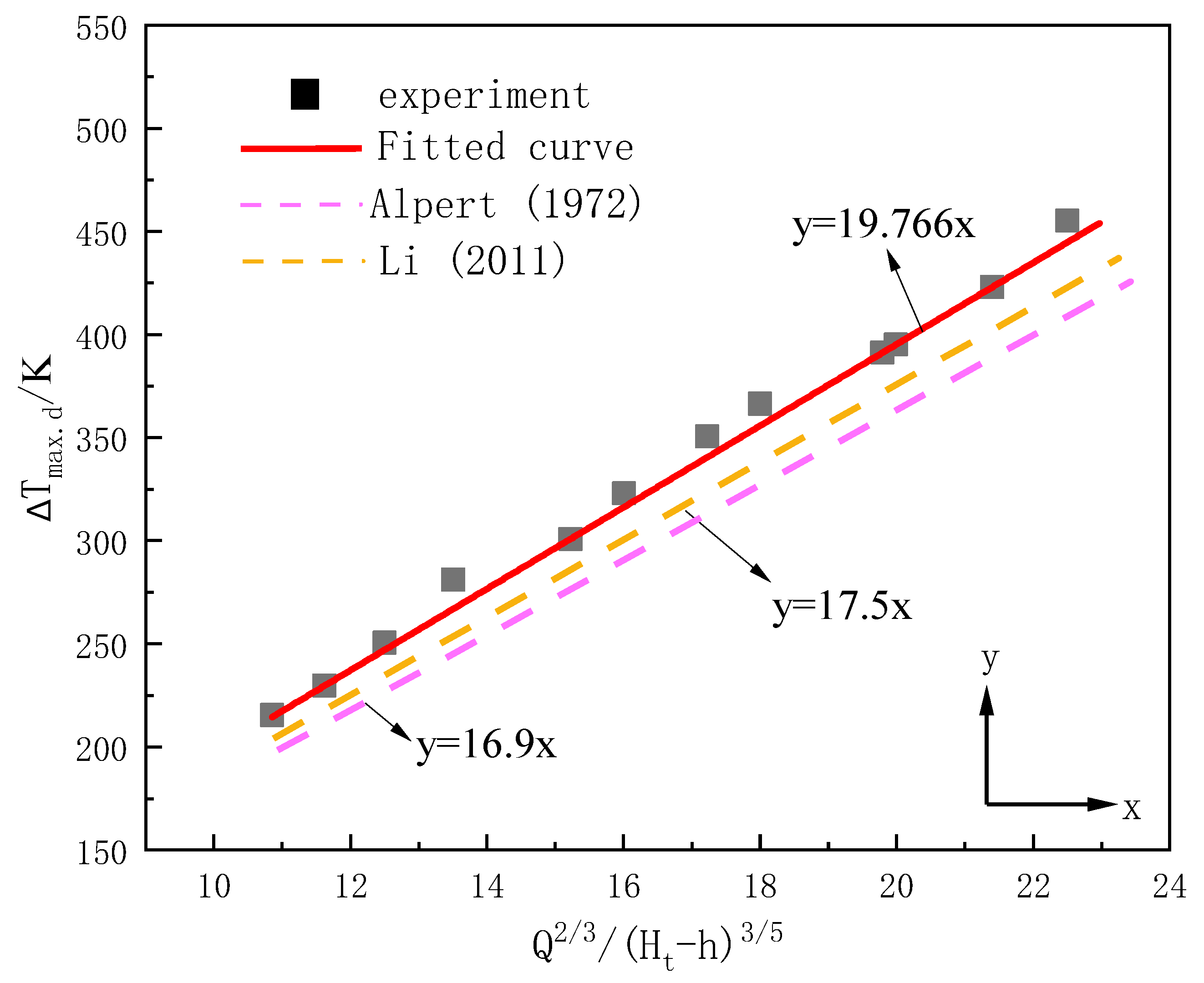
Figure 8 illustrates the variation in the maximum ceiling temperature rise with HRR and fire source height for centrally located fires. A linear regression was applied to the experimental data, and the resulting correlation is given by Equation (10).
where ΔTmax,c is the maximum smoke temperature rise beneath the ceiling when the fire source is located at the centerline, K; Ht is the height of the tunnel, m; and h is the height of the fire source location, m.
Figure 8.
Linear fitting of center ceiling maximum temperature rise. The data indicates a significant difference compared to previous studies under various conditions [7,8,11].
The coefficient in Equation (10) is noticeably larger than those reported by Alpert [11] and Li [7,8], which can be primarily attributed to differences in tunnel geometry. In Alpert’s experiments, the tests were conducted in a large-scale enclosed compartment where the fire source was not closely confined by boundaries. This allowed high-temperature smoke to spread laterally over an extensive area, resulting in reduced thermal energy accumulation beneath the ceiling and a relatively lower rate of ceiling temperature rise. In contrast, Li’s experiments employed two tunnels with different cross-sections: Tunnel A (width 250 mm, height 250 mm) and Tunnel B (width 450 mm, height 393 mm), and were validated using data from full-scale multi-lane tunnel tests (e.g., the Memorial Tunnel). Both models featured a height-to-width ratio less than or equal to 1, corresponding to the typical characteristics of multi-lane tunnels. The coefficient in Li’s formula is larger than that in Alpert’s, which is attributed to the restriction imposed by the tunnel sidewalls on the smoke flow, leading to heat concentration.
In contrast, the present study is based on a reduced-scale experimental setup representative of a single-lane tunnel, characterized by a height-to-width ratio of 1.11, which is greater than that of Li’s multi-lane model. Under such narrow cross-sectional conditions, lateral smoke dispersion is strongly restricted, causing a larger fraction of the thermal plume to accumulate beneath the ceiling. Consequently, the maximum ceiling temperature rise increases more rapidly with increasing HRR, resulting in a larger coefficient in the fitted correlation. Specifically, this single-lane geometry yields a coefficient that is approximately 13% higher than the value for multi-lane tunnels.
3.3. Maximum Smoke Temperature Rise for Off-Center Fires
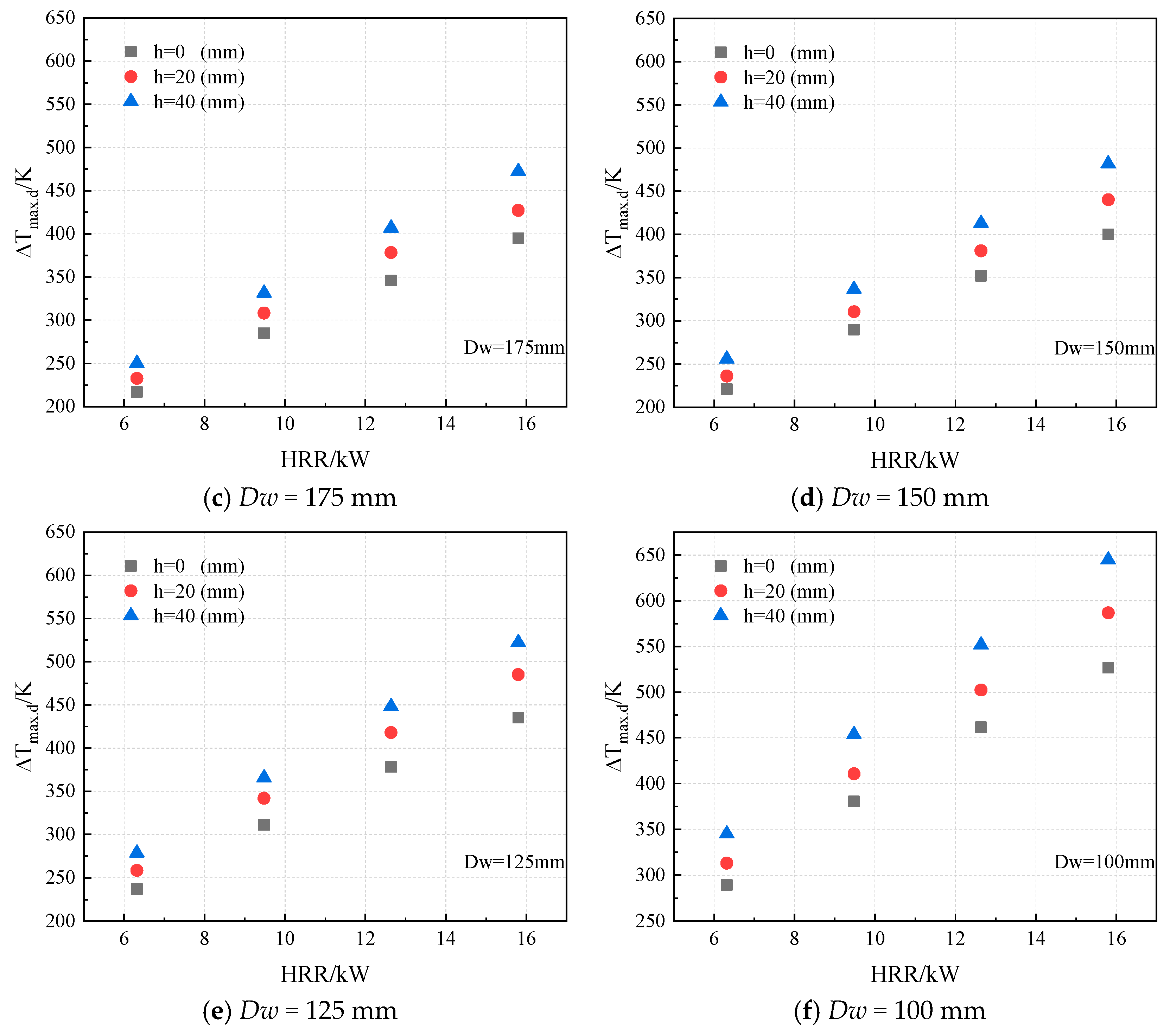
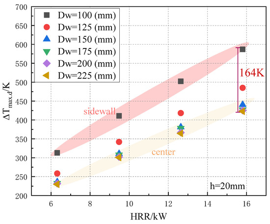
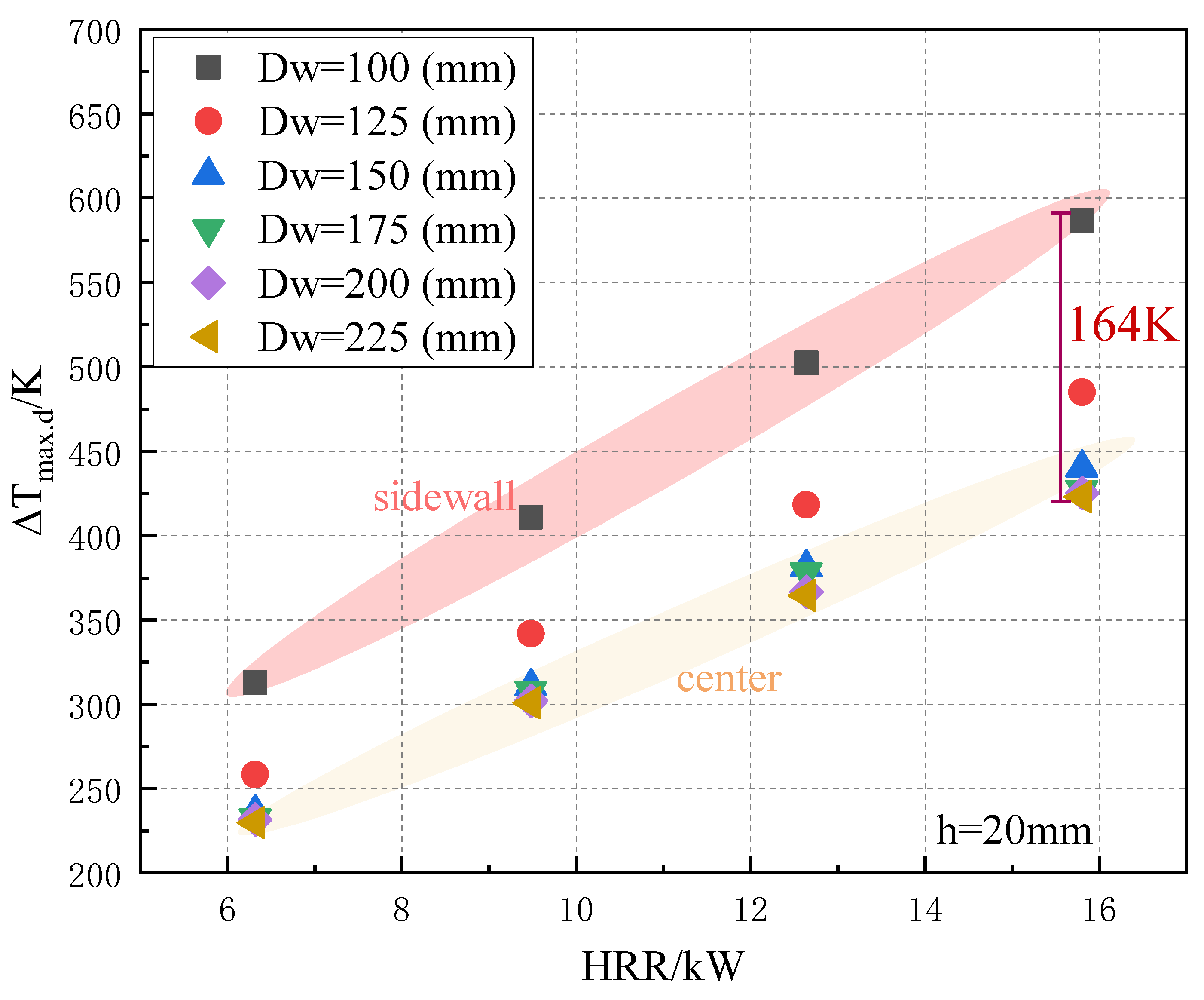
Figure 9 illustrates the variation in the maximum ceiling temperature rise with HRR and Dw for a fire source height of 20 mm. It was observed that, during the initial stage as the fire source moved toward the sidewall, the ceiling temperature rise remained relatively unchanged. This behavior can be attributed to the relatively large height-to-width ratio of the tunnel and the fact that the fire source width occupied nearly half of the tunnel width. Under these conditions, air entrainment from the two tunnel portals was inherently limited; consequently, when the fire source moved within the central region of the tunnel cross-section, the influence of the sidewalls on air entrainment was relatively weaker.
Figure 9.
Variation in ceiling maximum temperature rise on h = 20 mm.
However, as the fire source approached the sidewall, a pronounced increase in the ceiling temperature rise was observed. In particular, when the fire was located adjacent to the sidewall (Dw = 100 mm), the ceiling temperature rise increased dramatically. For example, when HRR is 15.8 kW, the maximum ceiling temperature rise was approximately 422 K for a centrally located fire, whereas it reached to about 586 K when the fire source was wall-adjacent, corresponding to an increase of approximately 39%.
This significant increase in ceiling temperature under wall-adjacent fire conditions is primarily attributed to the confinement effect imposed by the sidewall. The presence of the sidewall restricts air entrainment into the fire plume, reduces mixing with ambient air, and promotes flame elongation. Consequently, a larger fraction of the high-temperature plume impinges on the tunnel ceiling, intensifying heat accumulation and resulting in a higher maximum ceiling temperature rise [47,48,49]. Similar conclusions have been reported in previous studies [50], which demonstrated that sidewall confinement limits air entrainment, increases flame height, and ultimately leads to higher ceiling temperatures.
Based on the above analysis, it is evident that the HRR, fire source height, and transverse fire location all exert significantly influence on the ceiling temperature rise. Compared with a centrally located fire, a wall-adjacent fire consistently results in a higher maximum ceiling temperature rise, with this temperature difference increases progressively as the fire source approaches the sidewall.
Accordingly, to investigate the influence of the distance between the fire source and the sidewall on the ceiling temperature rise, a relative parameter is introduced to quantify this effect, as expressed in Equation (11):
where is the maximum temperature rise beneath the tunnel ceiling when the fire source center is located at a distance from the sidewall, °C; DW is the distance between the fire source and the sidewall, m; and W is the width of the tunnel.
Figure 10 illustrates the relationship between the ceiling temperature rise and the transverse distance of the fire source from the sidewall. As the fire source approached the sidewall, the ceiling temperature rise exhibited a non-uniform variation. When the wall distance was greater than or equal to 150 mm, the ceiling temperature rise remained nearly constant. As the wall distance decreased to 125 mm, a gradual increase in the ceiling temperature rise was observed, whereas a sharp increase occurred when the distance was further reduced to 100 mm.
Figure 10.
Temperature rise with sidewall distance at different HRR.
Based on these experimental observations, the tunnel cross section was divided into three regions according to the distance between the fire source and the sidewall: the central region, the near-wall region, and the wall-attached region. As shown in Figure 10, the sensitivity of the ceiling temperature rise to the transverse fire location increased as the fire source moved toward the sidewall.
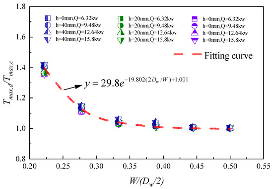
To quantitatively characterize the relationship between the ceiling temperature rise and the transverse fire location in the present experiments, a dimensionless wall distance and a dimensionless ceiling temperature rise are introduced, and the corresponding correlation is expressed in Equation (12):
Based on Equation (12), the functional relationship was determined by fitting the dimensionless experimental data, and the fitting results are shown in Figure 11. The fitting exhibited good agreement, with a correlation coefficient of 0.975. The resulting dimensionless correlation for wall-adjacent fires is given in Equation (13). Accordingly, the final predictive model for the maximum ceiling temperature rise incorporating transverse fire location is expressed in Equation (14):
Figure 11.
Fitting diagram of dimensionless ceiling maximum temperature rise to dimensionless near-wall distance.
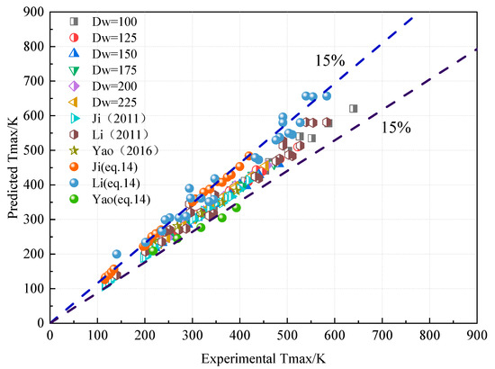
Figure 12 compares the predictions of Equation (14) with the experimental data from the present study. Overall, good agreement is observed between the model predictions and the experimental results of the present work, consistent with previous studies [7,16,18]. Additionally, the experimental data from previous studies were substituted into Equation (14), as shown in Figure 12. The predicted values for Ji and Li are significantly higher than the experimental values, whereas the predictions for Yao [18] are lower than the measured values. This is attributed to the fact that the height-to-width ratios in the experimental models of Ji and Li were smaller than that in the present study, leading to an overestimation by Equation (14). Conversely, the height-to-width ratio in Yao’s model was larger than that in the present study, resulting in underestimation by the present formula.
Figure 12.
Comparison of experimental and predicted values of dimensionless ceiling maximum temperature rise (Note: Li’s tunnel dimensions in Ref. [7] are 0.45 m width × 0.39 m height; Ji’s tunnel dimensions in Ref. [16] are 1.5 m width × 0.6 m height; Yao’s tunnel dimensions in Ref. [18] are 0.4 m width × 0.5 m height).
In summary, the proposed model provides reliable predictions for reduced-scale tunnels with an aspect ratio of 1.11, and it also shows consistency with previous studies. The majority of the data points fall within a deviation range of ±15%, indicating satisfactory predictive performance.
3.4. Limitations
While this study provides valuable insights into fire dynamics in single-lane tunnels, several limitations should be noted. First, the experimental model utilized galvanized steel sidewalls. Although the ceiling was insulated with gypsum board to simulate the adiabatic boundary of a concrete tunnel, the high thermal conductivity of the metal sidewalls may result in higher heat dissipation compared to full-scale concrete tunnels. Consequently, the measured temperature rise might be slightly conservative. Second, the LPG fire source represents a steady-state heat release, which differs from the transient growth phase of real vehicle fires involving solid combustibles. Finally, as the experiments were conducted based on Froude similarity, the radiative heat transfer scaling is not perfectly preserved, which is a common challenge in reduced-scale fire testing. Future studies will aim to address these issues through full-scale validations or numerical simulations considering conjugated heat transfer. Overall, while the model validates well for the aspect ratio of 1.11, the coefficients are sensitive to geometry. Comparison with Figure 12 suggests a positive correlation between the coefficients and aspect ratio, attributed to the stronger sidewall confinement in narrower tunnels.
4. Conclusions
This study investigated the flame behavior and ceiling temperature distribution in single-lane tunnel fires through a series of 1:10 reduced-scale experiments. The coupled effects of HRR, fire source height, and transverse fire location were analyzed. The main conclusions are drawn as follows:
- (1)
- Flame behavior is significantly governed by the transverse fire location. Centerline fires maintain a stable vertical structure due to symmetric air entrainment. In contrast, wall-attached fires exhibit asymmetric air entrainment, leading to a periodic dynamic behavior characterized by wall attachment, vertical elongation, detachment, and rebound toward the tunnel center.
- (2)
- The maximum ceiling temperature rise is positively correlated with the HRR and fire source height. The transverse fire location has a non-linear impact: the temperature response remains relatively stable in the central region but increases sharply as the fire approaches the wall. Specifically, wall-attached fires can increase the maximum ceiling temperature rise by up to 39% compared to centerline fires due to restricted air entrainment.
- (3)
- A predictive model for the maximum ceiling temperature rise in single-lane tunnels was developed. The decay coefficient for the single-lane geometry was found to be approximately 13% higher than that of conventional multi-lane tunnels, reflecting the enhanced heat accumulation in the narrow cross-section. The proposed model, which incorporates a dimensionless sidewall distance parameter, demonstrates satisfactory agreement with the experimental data.
This study reveals the distinct combustion behaviors and ceiling temperature characteristics associated with fires in single-lane tunnels. The proposed predictive model provides a valuable theoretical basis for structural fire protection design. A future study could be performed on the optimal deployment of heat detection systems and the development of firefighting and rescue strategies in such tunnel environments.
Author Contributions
Conceptualization, Y.L. and Y.X.; methodology, Y.X.; software, Y.X.; validation, Y.X. and Y.L.; formal analysis, Y.X. and L.L.; investigation, M.L. and X.Z.; resources, Y.X.; data curation, Y.L.; writing—original draft preparation, Y.X.; writing—review and editing, Y.L.; visualization, Y.X.; supervision, Y.L.; funding acquisition, Y.L. All authors have read and agreed to the published version of the manuscript.
Funding
This research was funded by the Beijing Natural Science Foundation (Grant No: 8222002).
Data Availability Statement
Data will be made available on request.
Conflicts of Interest
The authors declare no conflicts of interest.
References
- Huang, Y.B.; Luo, C.J.; Tang, F.; Liu, X.; Dong, B.Y.; Zhong, H. Estimating the flame length and ceiling maximum temperature in a branched tunnel fire with sloped mainline before shunting. Energy 2025, 322, 135655. [Google Scholar] [CrossRef] [Scilit]
- Huang, Y.B.; Luo, C.J.; Yan, H.; Dong, B.Y. Effect of asymmetric slope of mainline on smoke movement characteristic in bifurcated tunnel fire under natural ventilation. Case Stud. Therm. Eng. 2025, 74, 106959. [Google Scholar] [CrossRef] [Scilit]
- Vianello, C.; Fabiano, B.; Palazzi, E.; Maschio, G. Experimental study on thermal and toxic hazards connected to fire scenarios in road tunnels. J. Loss Prev. Process Ind. 2012, 25, 718–729. [Google Scholar] [CrossRef] [Scilit]
- Santos-Reyes, J.; Beard, A.N. An analysis of the emergency response system of the 1996 Channel tunnel fire. Tunn. Undergr. Space Technol. 2017, 65, 121–139. [Google Scholar] [CrossRef] [Scilit]
- Casey, N. Fire incident data for Australian road tunnels. Fire Saf. J. 2020, 111, 102909. [Google Scholar] [CrossRef] [Scilit]
- Leitner, A. The fire catastrophe in the Tauern Tunnel: Experience and conclusions for the Austrian guidelines. Tunn. Undergr. Space Technol. 2001, 16, 217–223. [Google Scholar] [CrossRef] [Scilit]
- Li, Y.Z.; Lei, B.; Ingason, H. The maximum temperature of buoyancy-driven smoke flow beneath the ceiling in tunnel fires. Fire Saf. J. 2011, 46, 204–210. [Google Scholar] [CrossRef] [Scilit]
- Li, Y.Z.; Ingason, H. The maximum ceiling gas temperature in a large tunnel fire. Fire Saf. J. 2012, 48, 38–48. [Google Scholar] [CrossRef] [Scilit]
- Karlsson, B.; Quintiere, J.G. Enclosure Fire Dynamics, 2nd ed.; CRC Press: Boca Raton, FL, USA, 2022. [Google Scholar] [CrossRef] [Scilit]
- Heskestad, G. Virtual Origins of Fire Plumes. Fire Saf. J. 1983, 5, 109–114. [Google Scholar] [CrossRef] [Scilit]
- Alpert, R.L. Calculation of response time of ceiling-mounted fire detectors. Fire Technol. 1972, 8, 181–195. [Google Scholar] [CrossRef] [Scilit]
- Kurioka, H.; Oka, Y.; Satoh, H.; Sugawa, O. Fire properties in near field of square fire source with longitudinal ventilation in tunnels. Fire Saf. J. 2003, 38, 319–340. [Google Scholar] [CrossRef] [Scilit]
- Gao, Z.H.; Liu, Z.X.; Ji, J.; Fan, C.G.; Li, L.J.; Sun, J.H. Experimental study of tunnel sidewall effect on flame characteristics and air entrainment factor of methanol pool fires. Appl. Therm. Eng. 2016, 102, 1314–1319. [Google Scholar] [CrossRef] [Scilit]
- Tang, F.; Hu, P.; He, Q.; Zhang, J.P.; Wen, J. Effect of sidewall on the flame extension characteristics beneath a ceiling induced by carriage fire in a channel. Combust. Flame 2021, 223, 202–215. [Google Scholar] [CrossRef] [Scilit]
- Xu, T.; Deng, L.; Tang, F. Flame extension scale and flow characteristics of inclined tunnel fires with various separation distances from sidewall. Tunn. Undergr. Space Technol. 2024, 154, 106090. [Google Scholar] [CrossRef] [Scilit]
- Ji, J.; Zhong, W.; Li, K.Y.; Shen, X.B.; Zhang, Y.; Huo, R. A simplified calculation method on maximum smoke temperature under the ceiling in subway station fires. Tunn. Undergr. Space Technol. 2011, 26, 490–496. [Google Scholar] [CrossRef] [Scilit]
- Haddad, R.K.; Zulkifli, R.; Maluk, C.; Harun, Z. Experimental Investigation on the Influences of Different Horizontal Fire Locations on Smoke Temperature Stratification under Tunnel Ceiling. J. Appl. Fluid Mech. 2020, 13, 1289–1298. [Google Scholar] [CrossRef] [Scilit]
- Yao, Y.Z.; Cheng, X.D.; Zhang, S.G.; Zhu, K.; Zhang, H.P.; Shi, L. Maximum smoke temperature beneath the ceiling in an enclosed channel with different fire locations. Appl. Therm. Eng. 2017, 111, 30–38. [Google Scholar] [CrossRef] [Scilit]
- Chen, C.K.; Zhang, Y.L.; Lei, P.; Jiao, W.B. A study for predicting the maximum gas temperature beneath ceiling in sealing tactics against tunnel fire. Tunn. Undergr. Space Technol. 2020, 98, 103275. [Google Scholar] [CrossRef] [Scilit]
- Li, L.M.; Cheng, X.D.; Cui, Y.; Dong, W.H.; Mei, Z.B. Effect of blockage ratio on the maximum temperature under the ceiling in tunnel fires. J. Fire Sci. 2013, 31, 245–257. [Google Scholar] [CrossRef] [Scilit]
- Jiao, W.B.; Chen, C.K.; Lin, Z.D.; Bao, Y.P.; Shi, L. Experimental study on the effect of longitudinal ventilation on spill fire characteristics in sloped tunnels. Int. J. Therm. Sci. 2024, 206, 109269. [Google Scholar] [CrossRef] [Scilit]
- Shafee, S.; Yozgatligil, A. An analysis of tunnel fire characteristics under the effects of vehicular blockage and tunnel inclination. Tunn. Undergr. Space Technol. 2018, 79, 274–285. [Google Scholar] [CrossRef] [Scilit]
- Gao, Z.H.; Li, L.J.; Sun, C.P.; Zhong, W.; Yan, C.B. Effect of longitudinal slope on the smoke propagation and ceiling temperature characterization in sloping tunnel fires under natural ventilation. Tunn. Undergr. Space Technol. 2022, 123, 104396. [Google Scholar] [CrossRef] [Scilit]
- Jiao, W.B.; Chen, C.K.; Lin, Z.D.; Bao, Y.P.; Shi, L. Experimental study on the burning characteristics and smoke temperature distribution of continuous spill fires in sloped tunnels. Tunn. Undergr. Space Technol. 2024, 152, 105884. [Google Scholar] [CrossRef] [Scilit]
- Chen, C.K.; Lu, T.; Zhang, Y.L.; Shi, C.L.; Jiao, W.B. Experimental study on temperature profile and critical velocity in bifurcated tunnel fire with inclined transverse cross-passage. Int. J. Therm. Sci. 2023, 186, 108120. [Google Scholar] [CrossRef] [Scilit]
- Lei, P.; Chen, C.K.; Zhao, D.Y.; Zhang, Y.L.; Xu, T.; Jiao, W.B. Study on heat allocation and temperature profile in a T-shaped branched tunnel fire with different branch slopes under natural ventilation. Tunn. Undergr. Space Technol. 2022, 126, 104508. [Google Scholar] [CrossRef] [Scilit]
- Oka, Y.; Kakae, N.; Imazeki, O.; Inagaki, K. Temperature property of ceiling jet in an inclined tunnel. In Proceedings of the 9th Asia-oceania Symposium on Fire Science and Technology, Hefei, China, 17–20 October 2013; pp. 234–241. [Google Scholar]
- Huang, Y.B.; Li, Y.F.; Li, J.M.; Li, J.X.; Wu, K.; Zhu, K.; Li, H.H. Experimental investigation on maximum gas temperature beneath the ceiling in a branched tunnel fire. Int. J. Therm. Sci. 2019, 145, 105997. [Google Scholar] [CrossRef] [Scilit]
- Lu, X.L.; Weng, M.C.; Liu, F.; Wang, F.; Han, J.Q.; Cheung, S.C. Study on smoke temperature profile in bifurcated tunnel fires with various bifurcation angles under natural ventilation. J. Wind Eng. Ind. Aerod. 2022, 225, 105001. [Google Scholar] [CrossRef] [Scilit]
- Chen, C.K.; Nie, Y.L.; Zhang, Y.L.; Lei, P.; Fan, C.G.; Wang, Z.Y. Experimental investigation on the influence of ramp slope on fire behaviors in a bifurcated tunnel. Tunn. Undergr. Space Technol. 2020, 104, 103522. [Google Scholar] [CrossRef] [Scilit]
- Fan, C.A.; Luan, D.; Bu, R.W.; Sheng, Z.Q.; Wang, F.Y.; Huang, X.Y. Can heavy rainfall affect the burning and smoke spreading characteristics of fire in tunnels? Int. J. Heat Mass Transfer 2023, 207, 123972. [Google Scholar] [CrossRef] [Scilit]
- Luan, D.; Bu, R.W.; Sheng, Z.Q.; Fan, C.A.; Huang, X.Y. Experimental study on the impact of asymmetric heavy rainfall on the smoke spread and stratification dynamics in tunnel fires. Tunn. Undergr. Space Technol. 2023, 134, 104992. [Google Scholar] [CrossRef] [Scilit]
- He, K.; Cheng, X.D.; Li, Y.Z.; Ingason, H.; Shi, Z.C.; Yang, H.; Zhang, H.P. Experimental study on flame characteristics of double fires in a naturally ventilated tunnel: Flame merging, flame tilt angle and flame height. Tunn. Undergr. Space Technol. 2021, 114, 103912. [Google Scholar] [CrossRef] [Scilit]
- Wei, S.Q.; Wan, H.X.; Zhou, X.H.; Zhang, Y.C. Experimental study on flame tilt angles of two unequal fires in a longitudinal ventilated tunnel. Tunn. Undergr. Space Technol. 2023, 137, 105125. [Google Scholar] [CrossRef] [Scilit]
- Haack, A. Fire protection in traffic tunnels: General aspects and results of the EUREKA project. Tunn. Undergr. Space Technol. 1998, 13, 377–381. [Google Scholar] [CrossRef] [Scilit]
- Vega, M.G.; Diaz, K.M.A.; Oro, J.M.F.; Tajadura, R.B.; Morros, C.S. Numerical 3D simulation of a longitudinal ventilation system: Memorial Tunnel case. Tunn. Undergr. Space Technol. 2008, 23, 539–551. [Google Scholar] [CrossRef] [Scilit]
- Barros-Daza, M.J. Validation of Subway Environmental Simulation (SES) for Longitudinal Ventilation: A Comparison with Memorial Tunnel Experimental Data. Fire 2025, 8, 8080314. [Google Scholar] [CrossRef] [Scilit]
- Fan, C.G.; Ji, J.; Sun, J.H. Influence of longitudinal fire location on smoke characteristics under the tunnel ceiling. Fire Mater. 2015, 39, 72–84. [Google Scholar] [CrossRef] [Scilit]
- Gao, Z.H.; Ji, J.; Fan, C.G.; Sun, J.H.; Zhu, J.P. Influence of sidewall restriction on the maximum ceiling gas temperature of buoyancy-driven thermal flow. Energy Build. 2014, 84, 13–20. [Google Scholar] [CrossRef] [Scilit]
- Quintiere, J.G. Scaling Applications in Fire Research. Fire Saf. J. 1989, 15, 3–29. [Google Scholar] [CrossRef] [Scilit]
- Li, Y.Z.; Ingason, H. Overview of research on fire safety in underground road and railway tunnels. Tunn. Undergr. Space Technol. 2018, 81, 568–589. [Google Scholar] [CrossRef] [Scilit]
- Mangs, J.; Keskirahkonen, O. Characterization of the Fire Behavior of a Burning Passenger Car. 2. Parametrization of Measured Rate of Heat Release Curves. Fire Saf. J. 1994, 23, 37–49. [Google Scholar] [CrossRef] [Scilit]
- Zeng, Z.; Xiong, K.; Lu, X.L.; Weng, M.C.; Liu, F. Study on the smoke stratification length under longitudinal ventilation in tunnel fires. Int. J. Therm. Sci. 2018, 132, 285–295. [Google Scholar] [CrossRef] [Scilit]
- Liu, X.J.; Xu, Z.D.; Dai, J.; Che, J.Y.; Wang, Y. Study on the flame propagation and temperature distribution in utility tunnel: The spread effect of cable fire. Appl. Therm. Eng. 2025, 279, 128101. [Google Scholar] [CrossRef] [Scilit]
- Fang, X.; Huang, Y.J.; Ren, F.; Zhang, H.; Li, C.C. Experimental study of the temperature profile induced by the tunnel wall fire plume at various source-ceiling heights. Case Stud. Therm. Eng. 2024, 60, 104761. [Google Scholar] [CrossRef] [Scilit]
- Huang, X.J.; Zhu, H.; Peng, L.; Zheng, Z.H.; Zeng, W.Y.; Bi, K.; Cheng, C.H.; Chow, W.K. Thermal Characteristics of Vertically Spreading Cable Fires in Confined Compartments. Fire Technol. 2019, 55, 1849–1875. [Google Scholar] [CrossRef] [Scilit]
- Salvagni, R.G.; Centeno, F.R.; Indrusiak, M.L.S. Burning rate, flame geometry and temperature of convection-controlled circular diesel oil pool fire under air crossflow conditions. J. Hazard. Mater. 2019, 368, 560–568. [Google Scholar] [CrossRef] [Scilit]
- Tang, F.; Hu, P.; Shi, C.L. Ceiling thermal impingement spread characteristics induced by wall-attached fires under various sub-atmospheric pressures. Energy 2021, 215, 119127. [Google Scholar] [CrossRef] [Scilit]
- Ji, J.; Fu, Y.Y.; Fan, C.G.; Gao, Z.H.; Li, K.Y. An experimental investigation on thermal characteristics of sidewall fires in corridor-like structures with varying width. Int. J. Heat Mass Transf. 2015, 84, 562–570. [Google Scholar] [CrossRef] [Scilit]
- Gao, Z.H.; Wan, H.X.; Ji, J.; Bi, Y.B. Experimental prediction on the performance and propagation of ceiling jets under the influence of wall confinement. Energy 2019, 178, 378–385. [Google Scholar] [CrossRef] [Scilit]



Disclaimer/Publisher’s Note: The statements, opinions and data contained in all publications are solely those of the individual author(s) and contributor(s) and not of MDPI and/or the editor(s). MDPI and/or the editor(s) disclaim responsibility for any injury to people or property resulting from any ideas, methods, instructions or products referred to in the content. |
© 2026 by the authors. Licensee MDPI, Basel, Switzerland. This article is an open access article distributed under the terms and conditions of the Creative Commons Attribution (CC BY) license.