Article

Understanding the Effects of Discrete Fuel Distribution on Flame Spread Under Natural Convection and Ambient Wind


1
Hunan Vocational Institute of Safety Technology, Changsha 410151, China
2
Northwest Institute of Nuclear Technology, Xi’an 710024, China
3
School of Civil Engineering, Central South University, Changsha 410075, China
4
Department of Architecture and Civil Engineering, City University of Hong Kong, Kowloon, Hong Kong 999077, China
*
Author to whom correspondence should be addressed.
Submission received: 18 December 2025 / Revised: 19 January 2026 / Accepted: 22 January 2026 / Published: 24 January 2026

Abstract

In this study, small-scale experiments were performed to examine fuel distribution effects on discrete flame spread behavior under natural convection and ambient wind. To this end, birch rod arrays with regularly varying column number (n) and array spacing (S) were designed. The results indicate that fuel distribution exerts a comparable influence on flame spread under both natural convection and ambient wind conditions. The flame spread rate (Vf), flame length (Lf), and mass loss rate (MLR) are insensitive to changes in S but have an exponential relationship with n. Based on the mass conservation law, prediction correlations for the mass loss rate based on S and n in the stable flame spread stage are proposed. We discovered that nondimensional mass loss has a power law dependence on the fuel coverage rate. In addition, radiative heat transfer dominates the flame spread process for the discrete array. Horizontal flame spread across discrete rod arrays exhibits critical spacing under natural convection. Finally, we established a comprehensive heat transfer model for flame spread under natural convection conditions and obtained a derivation of a critical sustainability criterion for the discrete flame spread process, which considers radiative and convective heat transfer.

1. Introduction

Climate factors such as global warming have made wildfires more severe than historically expected [1]; frequent forest fires pose a significant threat to human safety and the properties of residents. A considerable quantity of charring fuels, dispersed with discretion, are found in the forest, and the gaps between these fuels cannot be ignored. These fuel gaps make the heat and mass transfer behavior in combustion more complex. Previous studies revealed that the risk of discontinuous solid fires may be greater than that of continuous solid fires [2,3]. However, insufficient research has been conducted on the fundamentals of discrete flame spread.
Studies have been conducted on the flame spread across discrete fuels involving the internal parameters of fuel bed, like the fuel length [4,5,6,7], the spacing [4,5,7,8,9,10,11,12] and the width [13,14,15,16] of the fuel arrays, environmental parameters such as the inclination angle of fuel arrays [15,17], and environmental wind [9,10,18,19,20,21,22]. Vogel and Williams [4] found that the combustion rate of a single stick in the array is faster than that of a single stick alone, and the critical condition for flame spread occurs when a stick’s total ignition time exceeds its flame spread duration [8]. Emmons and Shen [7] indicated that the flame spread rate is related to the fuel height-to-spacing ratio. In addition, prior research indicates that the flame spread rate initially accelerates followed by deceleration as the array spacing rises [9,10,11,12]. Zhao et al. [13] and Jiang et al. [14] explored how the array width affects the discrete flame spread characteristics of vertical multi-column arrays and established a prediction model for radiative heat transfer-dominated horizontal flame spread rate. Previous studies found that when the spacing of discrete fuel arrays is large, the pyrolysis front is approximately linearly related to time [17]. However, when the array spacing is small, the airflow and oxygen supply are insufficient, and the flame spread rate decreases [13]. Bu et al. [15,16] discovered that the discrete flame spread rate is independent of the array width and that heat transfer dominance shifts from radiation to convection with a rising fuel array inclination angle.
He et al. [9] found that at subcritical wind speeds, the flame spread rate varies with the stacking ratio and is not strongly dependent on the wind speed. Two different ignition modes are identified, with the flame front contacting and igniting the fuel directly at lower wind speeds and packing ratios and intermittently at higher wind speeds or larger packing ratios. Di Cristina et al. [20] found that as the wind speed increases, flame spread occurs sequentially in three states: continuous, discretized, and extinguished. Zhou et al. [18] established a linear power law correlation between the wind speed and flame spread rate, while Martins et al. [19] found a power law relationship between them. A prior study primarily examined the wind speed’s influence on flame spread behavior but lacked a detailed discussion of the effect on fuel distribution under ambient wind conditions.
The critical threshold governing horizontal flame spread in single-column arrays under natural convection has been investigated [22,23], but the threshold for multi-column fuels is not yet clear. Through a combination of experimental and theoretical methods, by observing and analyzing the variation in flame characteristic parameters under natural convection and ambient wind conditions, the influence mechanism of array columns and array spacings on the flame spread of discrete arrays is elucidated. Moreover, a critical discrete flame spread criterion is established through combined radiation–convection heat transfer analysis. We expect this work to provide a greater understanding of wildland fires.

2. Materials and Methods

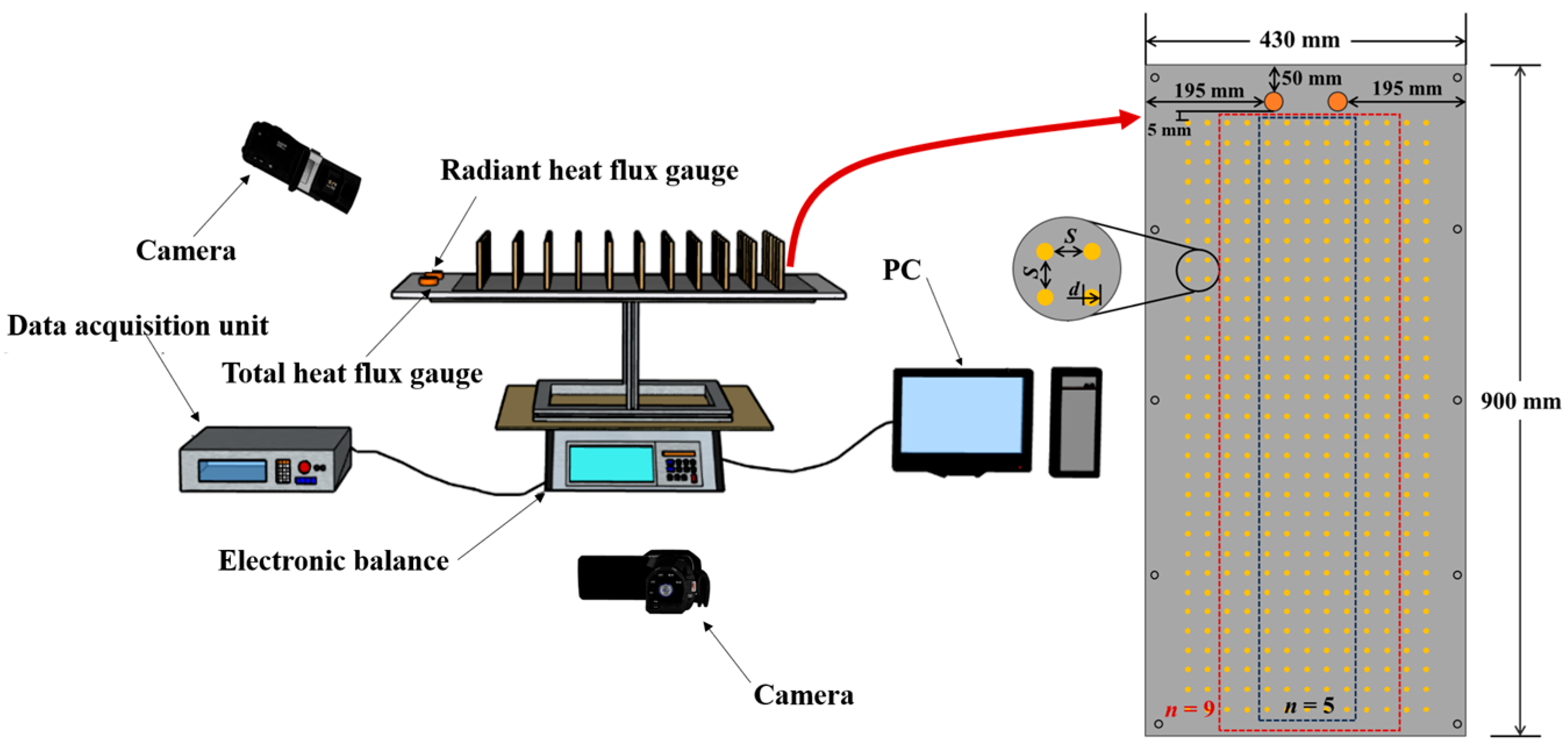
This study’s experimental setup for flame spread over discrete birch rod arrays is depicted in Figure 1. The experimental system comprises three parts: a perforated plate, electronic balance, and data acquisition system. Two digital cameras were used to capture videos of the experiments. One camera was placed parallel to the perforated plate to record the horizontal flame spread process at 50 fps, while the other camera was placed diagonally above the perforated plate to record flame shapes at 100 fps. A high-precision electronic balance was placed under the perforated plate to record the variation in sample mass at a frequency of 5 Hz. The measuring range and measuring accuracy of the electronic balance are 35 kg and 0.1 g, respectively. Two Gardon-type water-cooled heat flux gauges were positioned downstream of the perforated plate, closely attached to the fuel array. These gauges measured the heat flux in the preheat region. Both heat flux gauges (total and radiant) were symmetrically positioned 20 mm from the fuel array centerline. The maximum range, absorption rate, and extended uncertainty of the heat flux gauge are 50 kW/m2, 0.92, and ±3%, respectively. Convective heat transfer was calculated as the total heat flux with less radiative contribution.
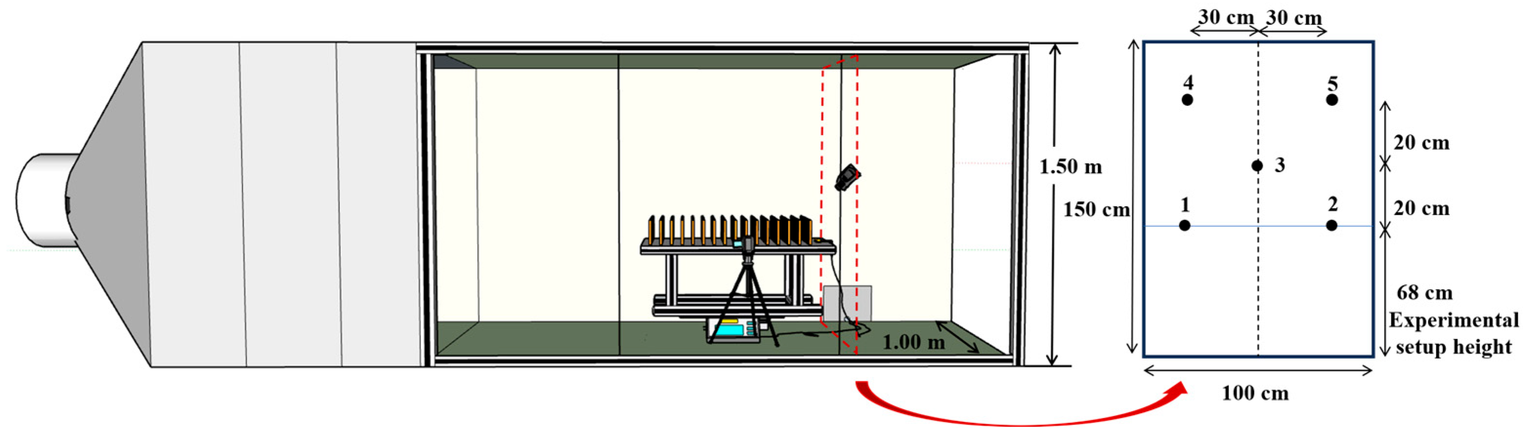
For ambient wind conditions, horizontal wind was supplied by a combustion wind tunnel system, which consists of an axial fan, rectification device, and air duct (4.8 m long × 1.0 m wide × 1.5 m high), as shown in Figure 2. The experimental setup was positioned 1.5 m downstream of the rectification section within the air duct. An L-type pitot tube, micro-manometer, and data acquisition module constitute the wind speed measurement system. Given that the moisture content of birch rods can affect flame spread behavior, the samples were dried at 85 °C. After 12 h, the sample mass was basically stable, and the sample was considered dried. Test specimens comprised birch rods with a 3.0 mm diameter and 96.4 mm length, and the accuracy of the cross-sectional diameter is ±0.1 mm. In the experiment, the birch rods were inserted into small holes in the perforated plate, with an insertion depth of 26.4 mm. At the start of each experiment, the first row of rods was ignited using a butane linear igniter.
Variations in array spacing and width were used to investigate the impact of fuel distribution on flame spread characteristics across discrete rod array. Moreover, the fuel array is always positioned at the middle of the perforated plate, the array positions for n = 5 and n = 9 are shown in Figure 1.
For natural convection, 5 array spacings (S = 5, 6, 7, 8, 9 mm) and 7 array column numbers (n = 1, 3, 5, 7, 9, 11, 13) were designed. In addition, for ambient wind (wind speed U = 0.5 m/s), six array spacings (S = 9, 11, 13, 15, 17, 19 mm) and four column numbers (n = 1, 5, 9, 13) were set up. Table 1 summarizes all test conditions investigated in this study, for a total of 59 cases. Experiments were repeated 2–3 times to verify data reproducibility.

3. Results

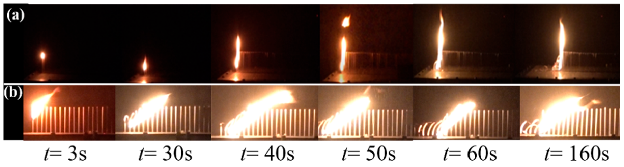
The flame spread process of single-column discrete rod arrays (S = 5 mm) is depicted in Figure 3. Under natural convection, initial ignition occurs at the first fuel rod, followed by vertical downward flame spread along the rod. Then, the second fuel rod is ignited, causing the flames to merge and thereby sharply increasing the flame length. The steady stage commences when heightened heat release rates yield uniform flame spread and stable flame lengths, and the analyzed parameters are time-averaged values from this stage. Under ambient wind conditions, the flames tilt and touch multiple rods at the same time. As depicted in Figure 3, during the discrete flame spread process, the top of downstream unburned birch rods is always the first to be ignited.
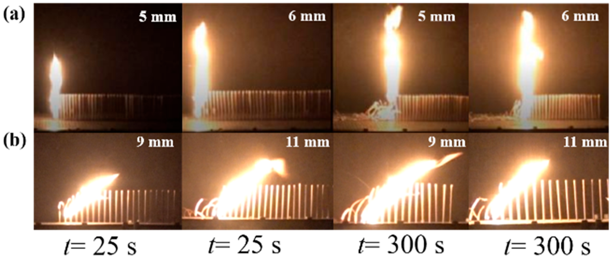
Figure 4 demonstrates flame length modulation by array spacing. At t = 25 s, once the array is ignited, the flame length exhibits progressive growth and is greatly affected by array spacing. When t = 300 s, the discrete flame spread develops to a stable stage, and the flame length shows weak dependence on array spacing.
Under natural convection, as the array spacing increases, flame spread ceases in arrays with fewer columns. When array spacing reaches 9 mm, the flame does not spread across all configurations. In addition, under ambient wind, horizontal wind is applied to the arrays, and the flame can spread at S = 9 mm. As the array spacing increases, the flame cannot spread at S ≥ 15 mm for single-row arrays. However, for multi-column arrays, there are no instances of the flame extinguishing on its own at array spacings in the range of 9–19 mm.
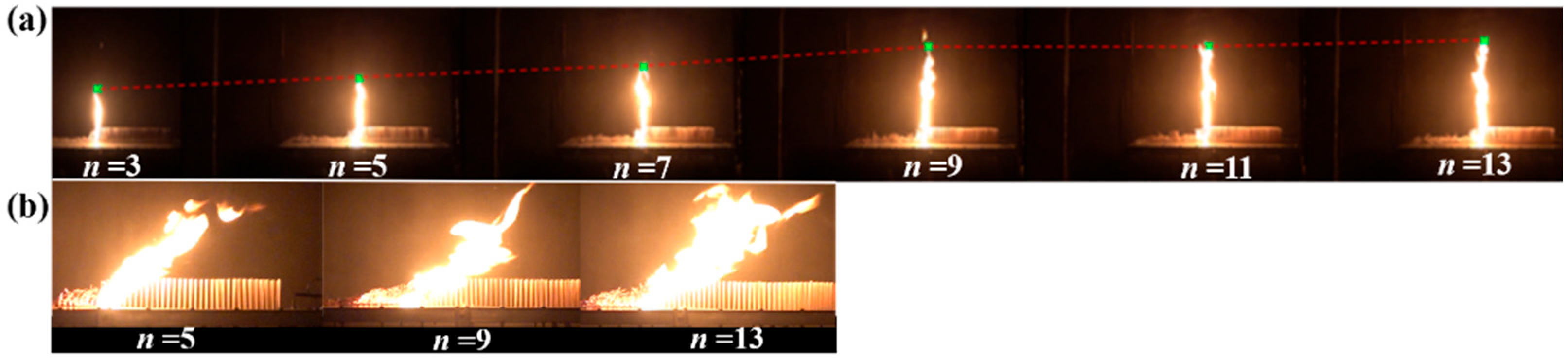
Figure 5 demonstrates flame length modulation by array width. When n ≤ 8, the flame length varies positively with an increased column number, and it is more sensitive to the variation in the column number. When n > 9, the increasing trend of flame length decelerates as the column number increases.
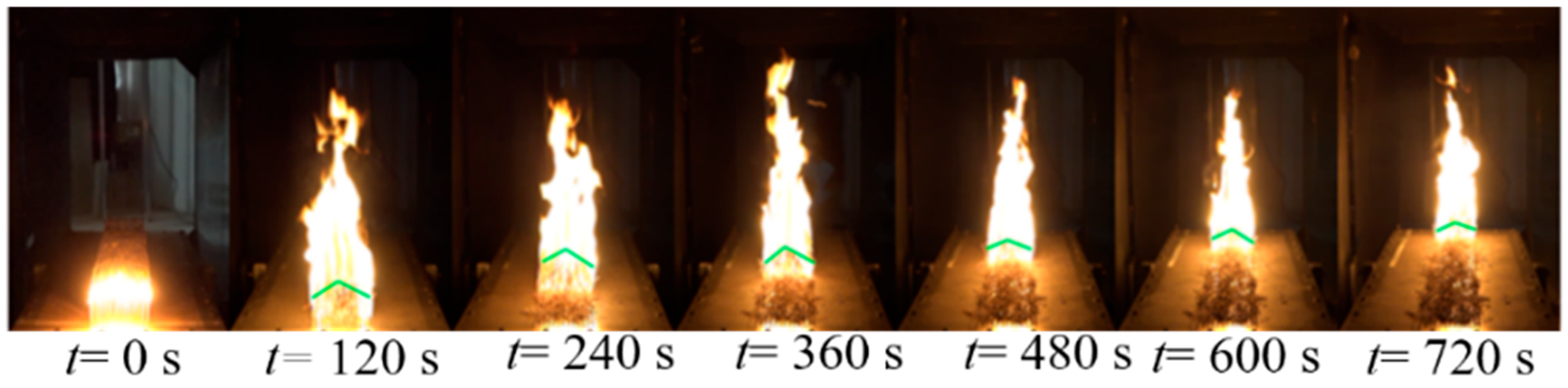
Figure 6 presents the front view of the discrete flame spreading through discrete rod arrays with S = 7 mm and n = 13. After being ignited by a linear ignition source, the fuel rods generate isolated flames. As the flames spread, air entrainment is enhanced, and flame merging occurs, resulting in the flame length increasing significantly. Flame heat flux to downstream unburned regions increases, and the downstream fuel rods are fully preheated, accelerating the speed of flame spread. Meanwhile, Figure 6 shows the shape of the flame front. Due to the higher incident heat flux received by the fuel on the centerline of the array, the pyrolysis front of the fuel array always presents an inverted V-shape.

4. Discussion

4.1. Flame Spread Rate

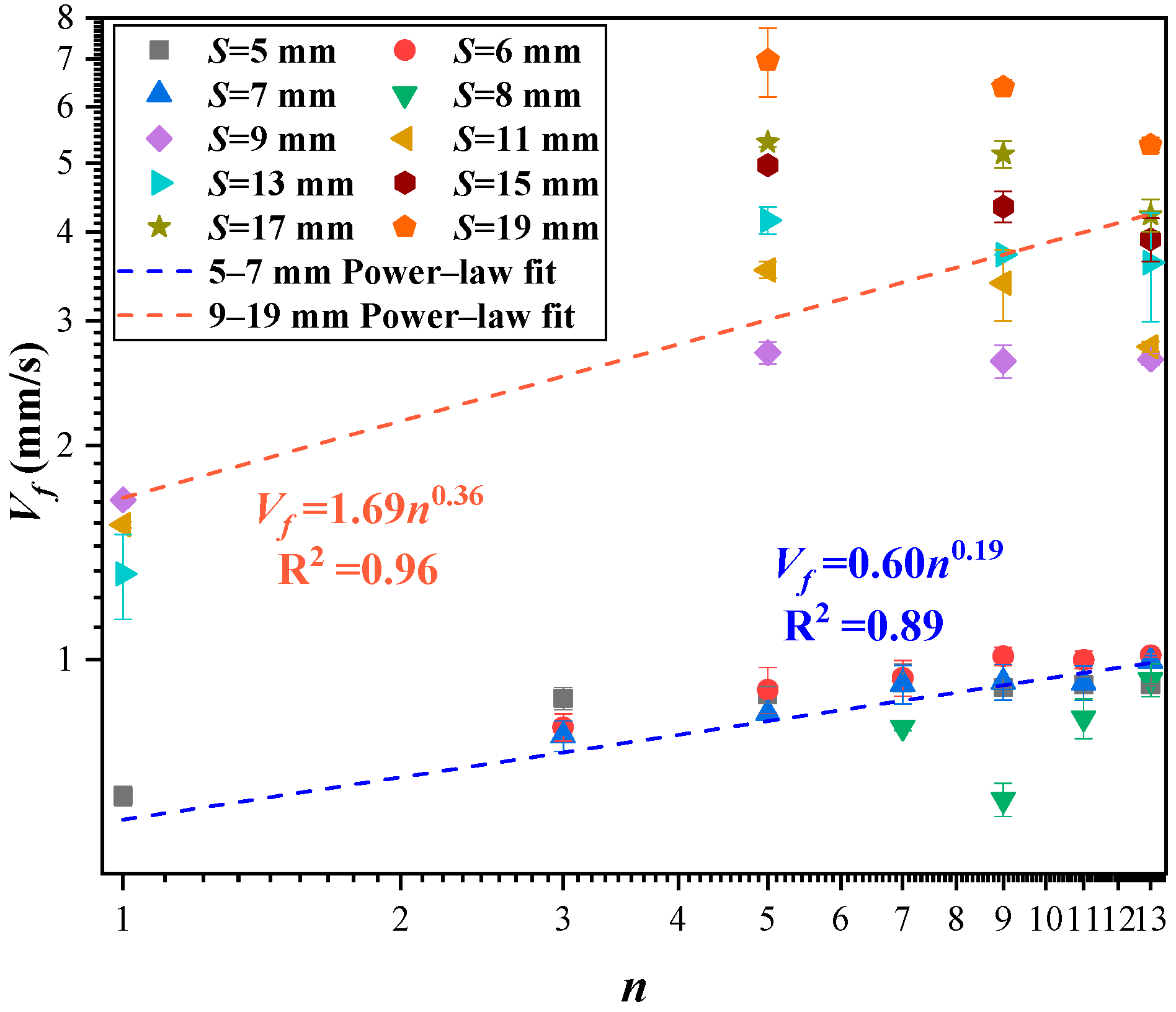
In this study, the flame spread rate Vf is determined through linear regression of the curve showing the position of the flame front over time. Figure 7 illustrates the dependency of Vf on column number. As depicted in Figure 7, Vf follows a power law dependence on n. Because of flame merging, Vf increases dramatically in multi-column arrays compared to single-row arrays. Under natural convection (S ≤ 8 mm), Vf increases exponentially with the increase in n of the fuel array. At S = 8 mm, array spacing approaches critical spacing to sustain the flame spread, and the flame spread process is unstable, causing Vf to be relatively small.
Under ambient wind (S ≥ 9 mm), the flame is tilted, which expands the preheating zone and the burning area, thereby enhancing radiant and convective heat transfer. Consequently, flame spread becomes possible across arrays with larger spacings, and the critical flame spread spacing for single-column arrays rises from 5 mm to 13 mm.
To further understand the coupling effect of S on the variation in discrete Vf with fuel distribution parameters, porosity ϕ is introduced [23,24]:
ϕ = S p S b
Sp and Sb are the pore area and the total area of the fuel bed, respectively.
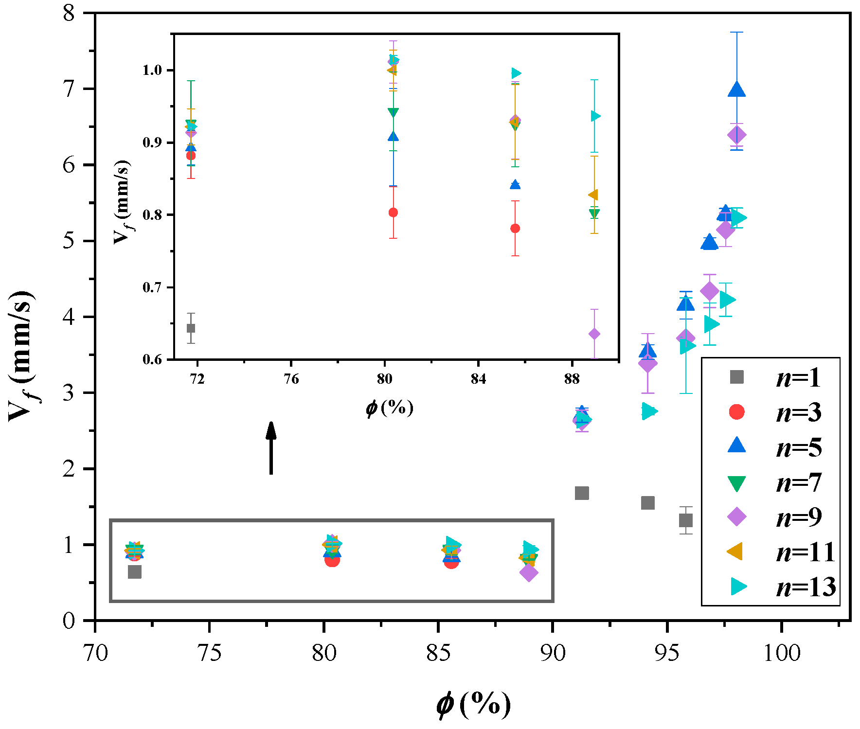
Figure 8 demonstrates the variation in Vf of discrete fuel arrays with the ϕ in this experiment. For S ≤ 8 mm, as ϕ increases, Vf does not present a monotonic trend but a trend that starts high and then drops, and it peaks when ϕ reaches a value of 80%. At excessive fuel density, the flame spread process of discrete fuel arrays is restricted by air entrainment; at this point, insufficient oxygen limits the combustion process. Increasing the porosity improves this phenomenon. However, once the optimal porosity is reached, further increases will make it more difficult to ignite the downstream unburned fuel area. Under natural convection, radiative heat transfer drives discrete flame spread, and excessive porosity can hinder radiative heat transfer, preventing flames from spreading. Figure 8 identifies 88.9% as the maximum porosity sustaining flame spread.
Under ambient wind (S ≥ 9 mm), the flame spread rate surges relative to natural convection conditions. For single-column arrays, the overly large porosity limits preheating of the burning area to the unburned area. Therefore, the spread rate decreases with increasing spacing. But for multi-column arrays, Vf increases with increasing porosity.
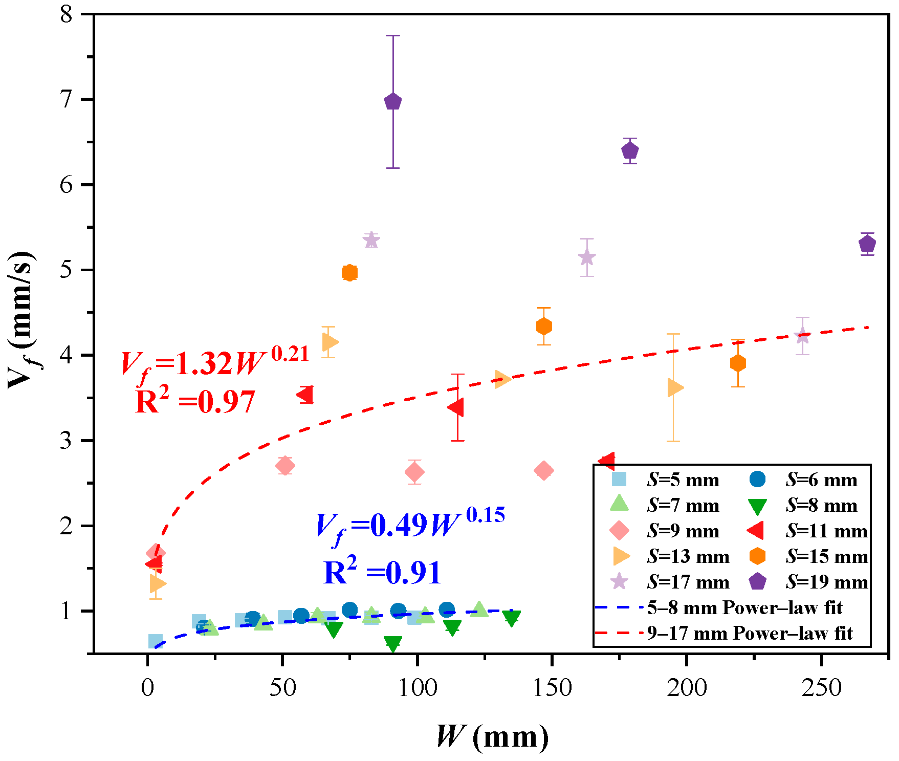
To elucidate the coupling effect of array spacing and column number on discrete flame spread, the array width (W) is introduced and defined as depicted in Equation (2). As W increases, the effect of S on Vf gradually decreases. As depicted in Figure 9, converting n and S to the array width W, the two parameters exhibit a power law relationship.
W = ( n 1 ) S + n d

4.2. Mass Loss Rate

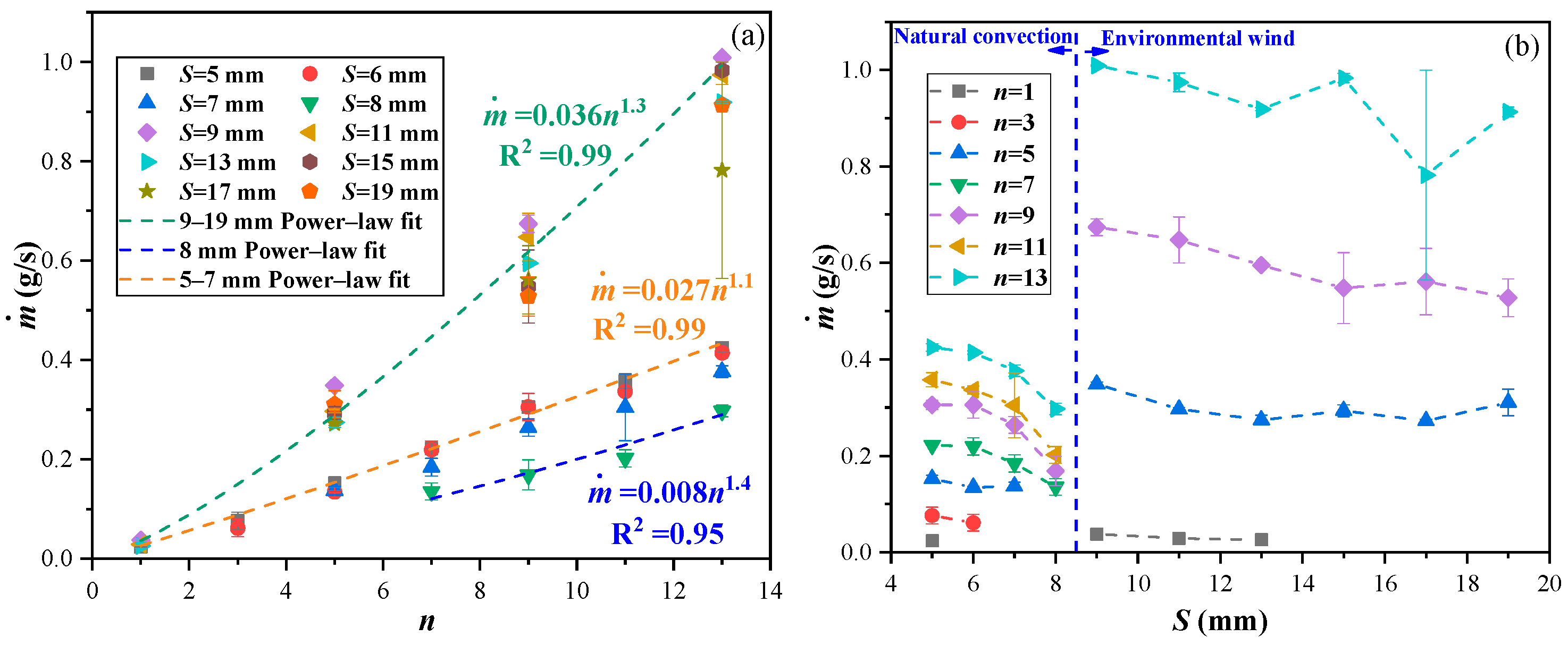
Concurrent combustion of multiple fuel rods serves as the primary control parameter for the discrete fuel array mass loss rate (MLR). As this study adopts a linear ignition method, the MLR increases with the increase in n. Moreover, the MLR presents a power law relationship with n, as depicted in Figure 10a.
Figure 10b shows that ambient wind tilts the flame, which increases the number of simultaneously burning rods. Therefore, when S ≥ 9 mm, the MLR increases significantly. Additionally, for both natural convection and ambient wind conditions, the MLR gradually decreases with increasing spacing.
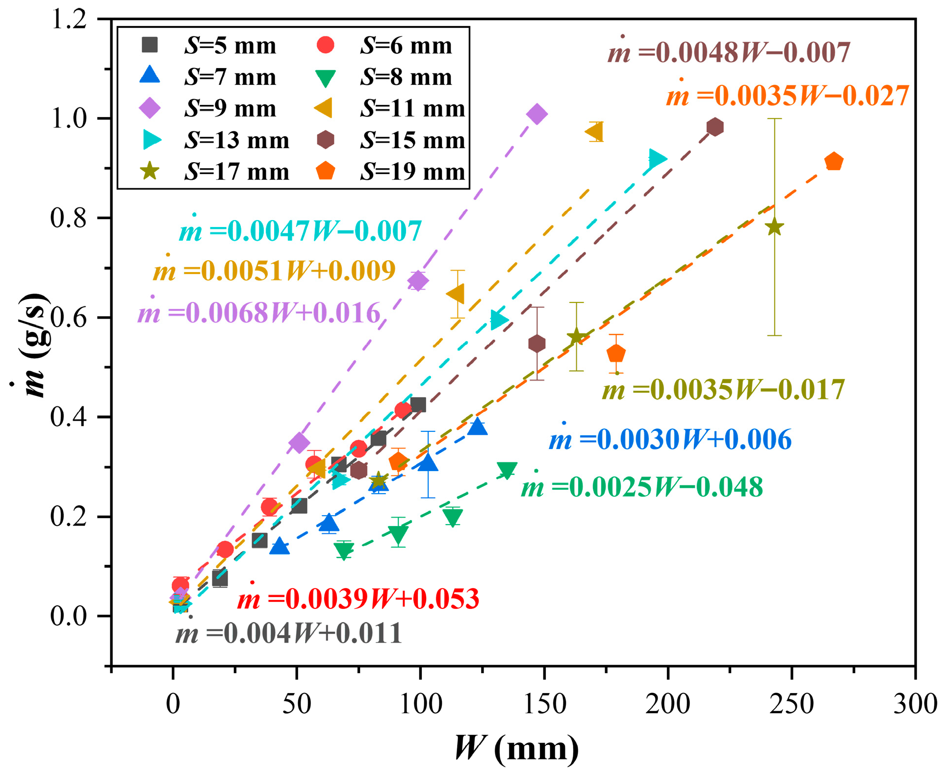
Furthermore, by analyzing the relationship between the MLR and W, a linear correlation between these two parameters is obtained, as depicted in Figure 11. The slope of the linear equation obtained from the fit is the largest when S = 9 mm, indicating that the MLR is most sensitive to changes in W at this time.
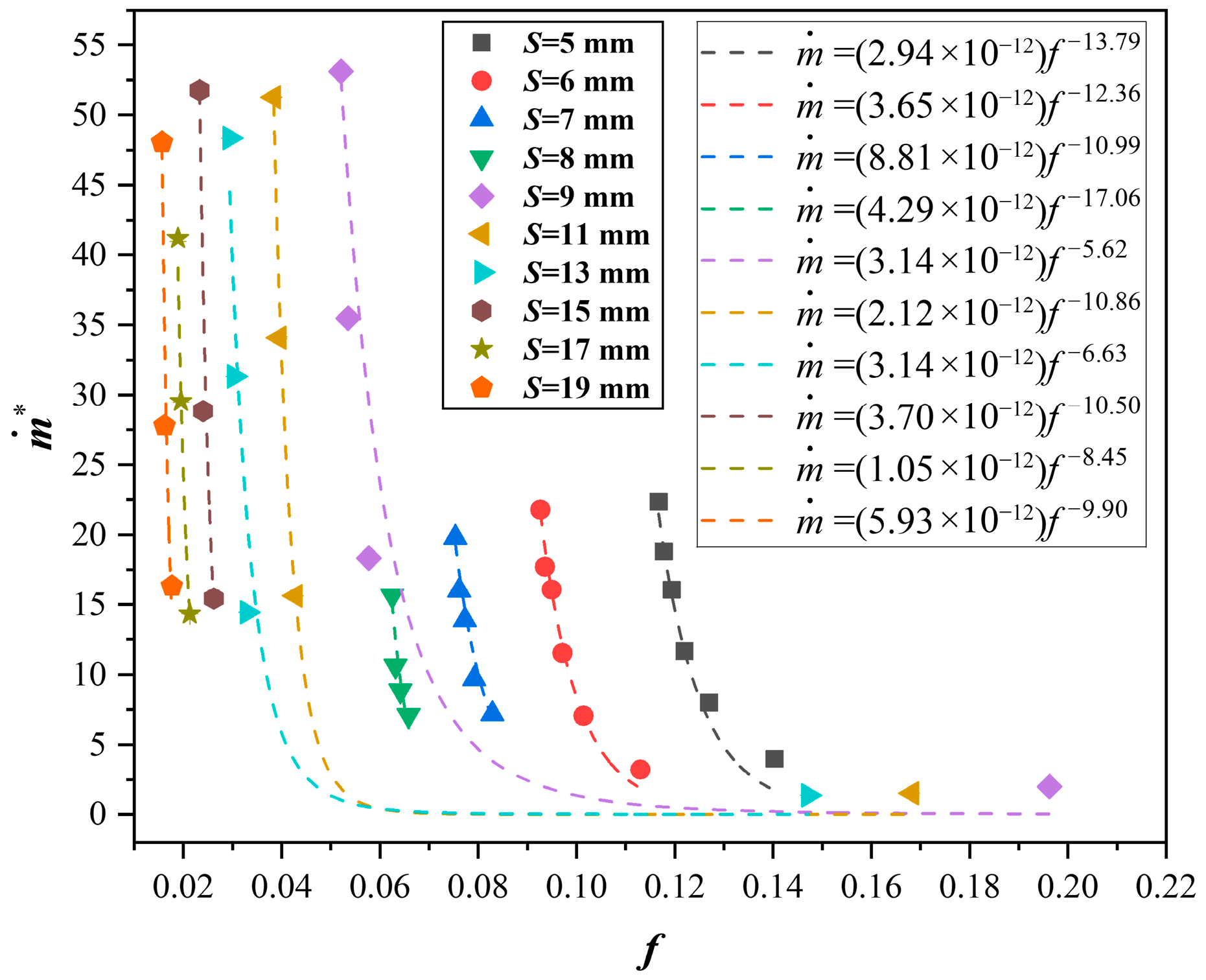
To further reveal the relationship between the MLR and fuel bed size, two parameters, nondimensional mass loss rate ( m ˙ * ) and fuel coverage rate (f), are introduced. m ˙ * is defined as the proportion of the MLR which was tested under the conditions of n = 1 and S = 1 mm, where m ˙ ( 1 , 1 ) was taken as 0.19 g/s:
m ˙ * = m ˙ ( n , S ) / m ˙ ( 1 , 1 )
f is defined as the ratio of the exposed area of the top of the fuel rods to the total area of the fuel bed and can be calculated as
f = r n π d 2 4 ( r 1 ) S + r d ( n 1 ) S + n d
where r and n correspond to the row and column numbers in the array, respectively, and d denotes the rod diameter. According to Equation (4), both r and n have a similar impact on the value of f. The f of the single-column array is relatively high, while that of the multi-column array decreases linearly with the increase in n. f concisely reveals the array distribution characteristics of uniformly discrete fuel beds, including the array row, column, and array spacing.
The relationship between m ˙ * and f is presented in Figure 12. As f increases, m ˙ * demonstrates a downward trend, and these two parameters exhibit a power law relationship with an overall R2 > 0.90.
The average MLR of discrete flame spread during its stable stage can be expressed as
m ˙ = 1 t 2 t 1 t 1 t 2 d m d t d t
where t1 and t2 are the beginning and ending times of the stable flame spread.
According to the mass conservation law, the MLR of the discrete fuel array can be calculated as
m ˙ = N ρ s d 2 v f , d
where N is the quantity of burning fuel rod, ρs is the fuel rod density, and vf,d is the downward vertical flame spread rate of the infinite array, which can be expressed as follows [25]:
v f , d = C ( k ρ c p ) g ( k ρ c p ) s T f T p T p T α g g ( T f T ) T 1 / 3
where C is a constant determined by the experiment, kg and ρg are the thermal conductivity and density of the gas, respectively, evaluated at the film temperature (Tfilm = (Tf + Ts)/2). ks, ρs and Tp are the thermal conductivity, density and pyrolysis temperature of birch wood, respectively. Tf is the flame temperature, T is the ambient temperature, αg is the gaseous thermal diffusivity at the film temperature, and cp,g and cp,s are the specific heat capacity of gas and fuel, with values of 1.0004 kJ/(kg k) and 1.5 kJ/(kg k), respectively.
There is an empirical correlation between N and n under natural convection (S ≤ 8 mm), and it can be expressed as follows [16]:
N = 1.36 n 1.19
Under ambient wind (S ≥ 9 mm), N can be written as
N = 4.76 n 1.10
By substituting Equations (7)–(9) into Equation (6), the MLR can be obtained:
m ˙ = 1.36 n 1.19 ρ s d 2 v f , d , S 8 mm m ˙ = 4.76 n 1.10 ρ s d 2 v f , d , S > 8 mm
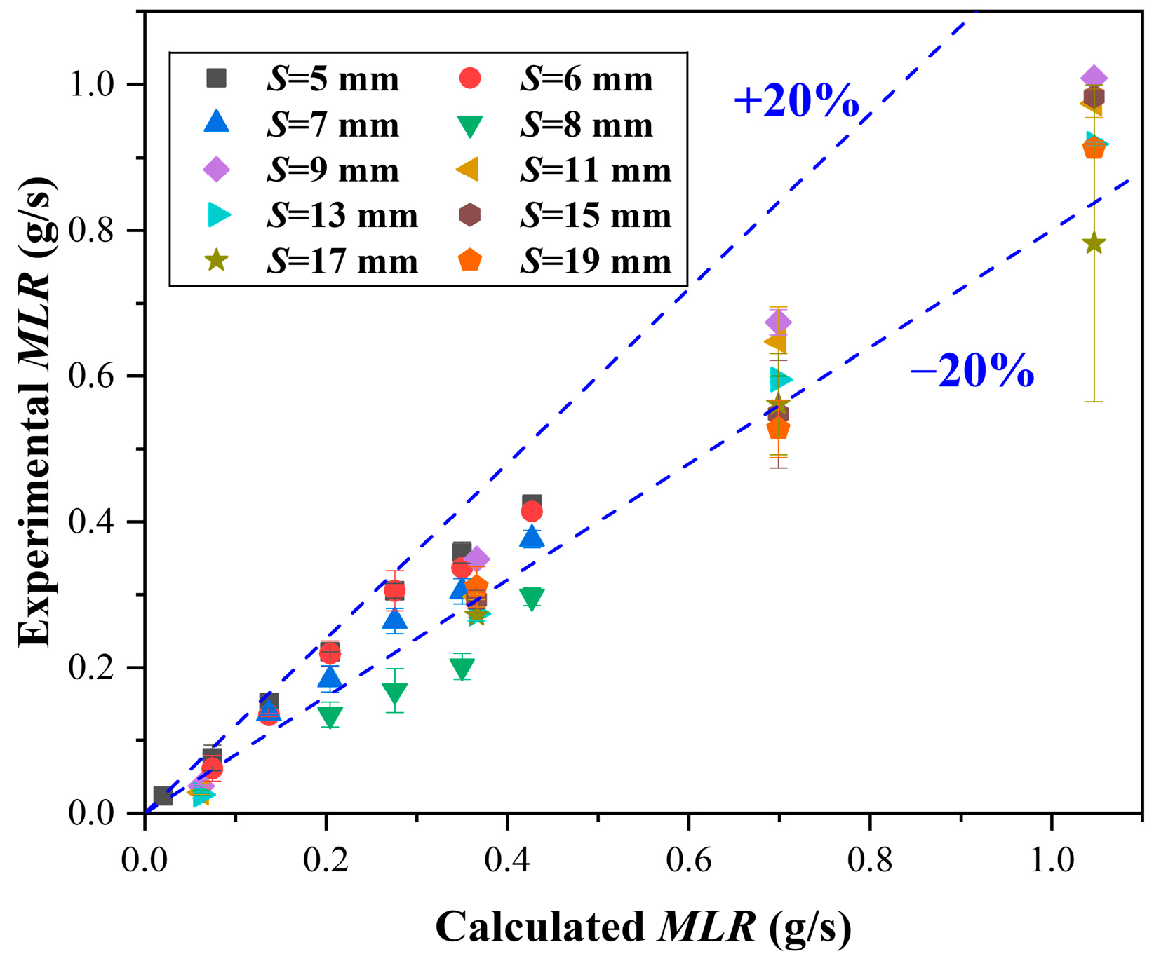
Figure 13 demonstrates a comparison of the calculated and experimental values. Under natural convection, there is strong consistency between model predictions and experimental data, and all data are within the 20% uncertainties. However, under ambient wind, the fuel rods burn incompletely; however, the model is established on the premise of complete combustion, so the calculated values are generally high.

4.3. Flame Length

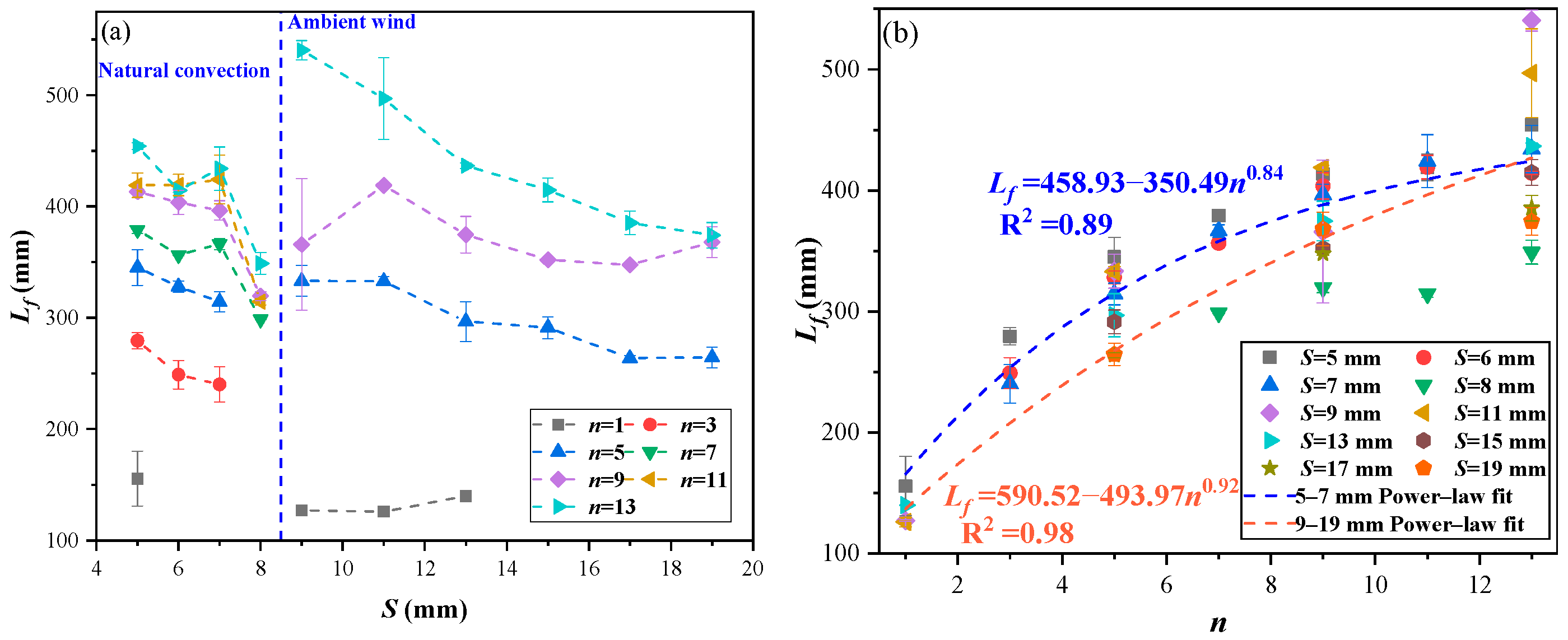
Figure 14 demonstrates the dependence of the flame length (Lf) on S and n. Ambient wind elongates the flame. Therefore, under external wind conditions, Lf is larger than that under natural convection. Moreover, at all spacings, Lf demonstrates a decreasing tendency with the increase in S, but the decrease is not significant (Figure 14a). When S increases, the heat feedback is limited, which further affects Lf. When n increases, flame-merging behavior is enhanced, resulting in an increase in Lf, and an exponential relationship is found between the flame length and column number (Figure 14b).
Two nondimensional parameters, namely the nondimensional heat release rate Q ˙ * and the nondimensional flame length L f , are commonly used to describe the diffusion flame. The L f is expressed as
L f = L f / W
Q ˙ * is expressed as
Q ˙ * = Q ˙ / ρ c p , T g W 2 / 5
where ρ and c p , are the density and specific heat of air and are set as 1.165 kg/m3 and 1.0004 kJ/(kg k), g is the gravitational acceleration (10 m/s2), and Q ˙ is the heat release rate and can be expressed as
Q ˙ = m ˙ Δ H c
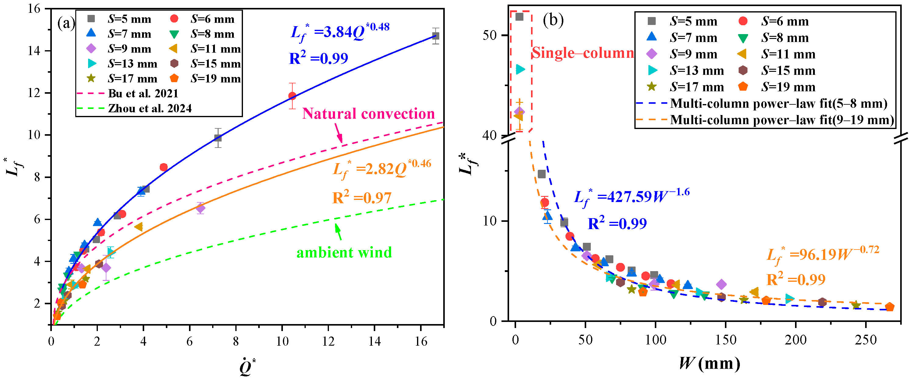
where ∆Hc is the heat of combustion, which is taken as 14.35 kJ/g [26]. The results of earlier research have demonstrated that L f displays a power law relationship with Q ˙ * [16,18]. This relationship can apply not only to individual flames driven by buoyancy but also to interacting flames and merging flames [27,28,29,30]. For buoyancy-driven flames, the Froude number (Fr) is proportional to Q ˙ * and has the following relationship: L f F r a Q ˙ * 2 a , 1 / 5 a 1 / 3 (where a is a constant determined by the experiment) [31,32].
Figure 15a demonstrates the variation in L f with Q ˙ * , and the two parameters exhibit a distinct power law correlation. The calculated values of a are 0.23 and 0.24, respectively, which are within the theoretical range. Therefore, the combustion of the birch rod arrays is controlled by buoyancy.
According to Equations (11) and (12), L f is also a function of W. Figure 15b demonstrates the trend of L f varying with W. The relationship between these two parameters also follows a power law relationship, which agrees well with the experimental data.

4.4. Critical Criterion for Flame Spread

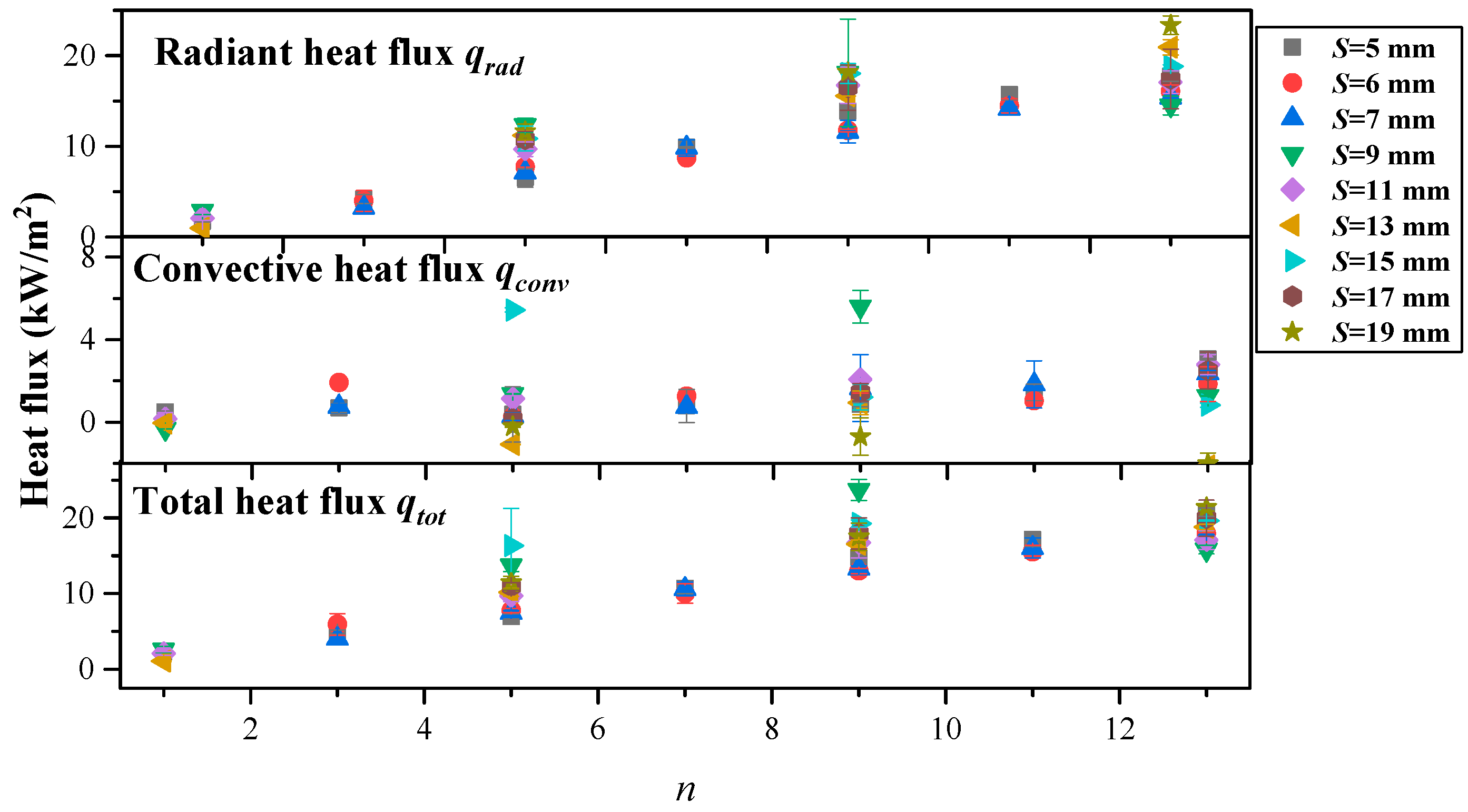
The maximum heat flux measured under the conditions of different array spacings and column numbers in the experiment is plotted in Figure 16. The experimental results suggest that radiant heat transfer is the main factor in the flame spread process and accounts for more than 68% of the maximum total heat flux. As n increases, both Lf and the flame area increase, and radiative heat transfer is enhanced.
Under natural convection, experimental phenomena show that the critical flame spread spacing increases with n. Incident heat flux serves as a critical parameter for evaluating discrete fuel array flame spread characteristics. If the total heat received by the unburned fuel exceeds the critical incident heat flux q ˙ i n , max q ˙ c r i t , the discrete flame spread process is sustained [33,34].
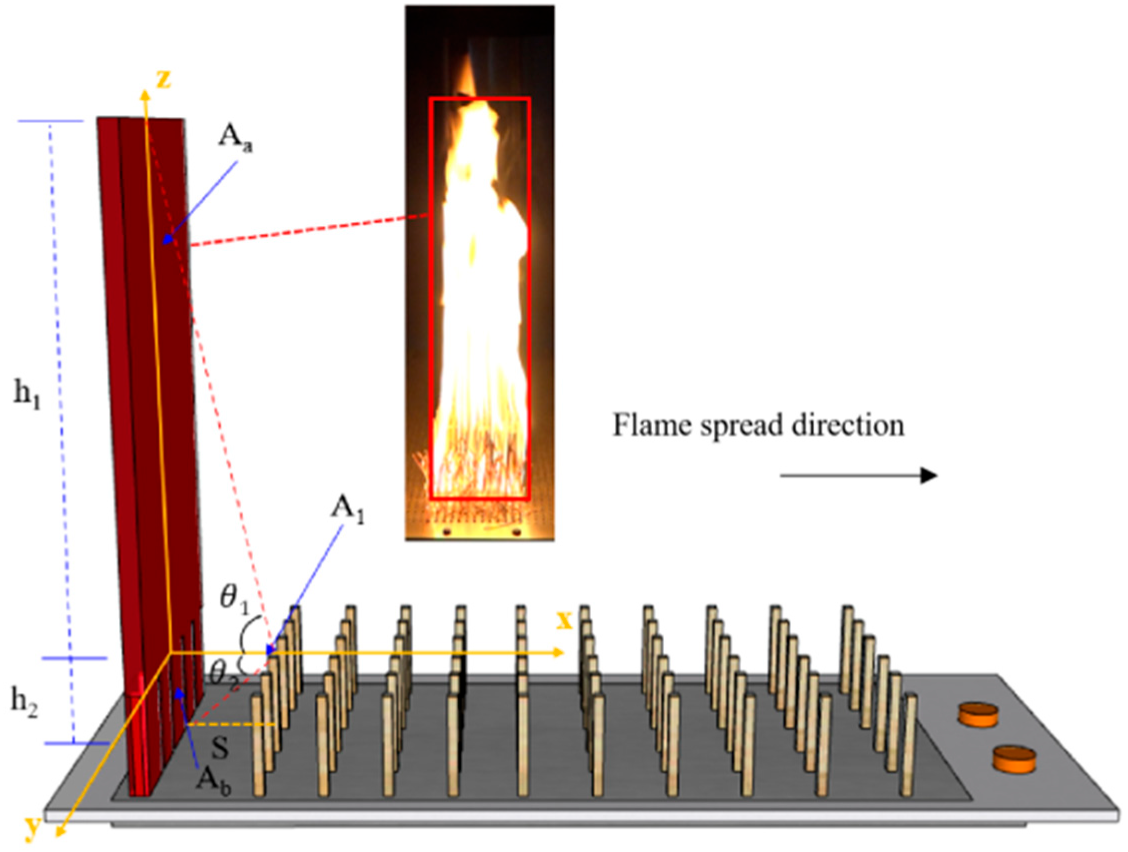
Figure 17 demonstrates the heat transfer scheme of horizontal discrete flame spread across discrete fuel arrays. Assuming the flame surface is a square flat plate, it is approximately a diffusing and gray surface. The fuel rods in the unburned area are all ignited from the upper surface. The upper surface of a row of fuel rods downstream of the combustion zone is defined as A1An, Aa, AbA1An, assuming that they are both diffusing emitters and diffusing reflectors and that the effective radiation density is uniform [35]. To investigate the radiative heat transfer between two surfaces, the view factor Fij is introduced, which is defined as the fraction of radiative heat that leaves surface i intercepted by surface j, and it can be expressed as
F i j = q i j A i J i = 1 A i A i A j cos θ i cos θ j π R 2 d A i A j
where q i j is the total emissivity intercepted by surface j leaving surface i, θi and θj are the angles between the two surfaces and their normal vectors, and R is the distance between two surfaces.
Figure 17 shows that by selecting the upper surface of downstream fuel rod A1 for analysis, the view factor can be obtained [35]:
F a 1 = 1 2 π d arctan S tan θ 1 d 2 / 4 + S 2 d 2 / 4 + S 2 + 2 arctan d cos θ 1 2 S sin θ 1
F b 1 = 1 2 π d arctan S tan θ 2 d 2 / 4 + S 2 d 2 / 4 + S 2 + 2 arctan d cos θ 2 2 S sin θ 2
where Fa1 and Fb1 are the view factors from the flames and combustion fuel rods to the surface of fuel rod A1, respectively. The included angles are θ 1 = arctan ( h 1 / S ) and θ 2 = arctan ( h 2 / S ) . Therefore, the view factor between the flame plane and the upper surface of A1 is derived:
F f M = F a 1 + F b 1
The radiative heat flux received by the unburned fuel is as follows [36]:
q ˙ r a d = F f M σ ε ( T f 4 T s 4 )
where σ is the Stefan–Boltzmann constant and is taken as 5.67 × 10⁻⁸ W/(m2K4), and ε is the surface emissivity, which can be approximately expressed as [37]
ε = 1 e 0.6 L f
The convective heat flux in the discrete flame spread process is as follows [36]:
q c o n v = h ( T g T s )
where h is the convective heat transfer coefficient, which can be obtained from the expression of the Nusselt number N u = h d / k a . For isothermal vertical plates, the expression of the Nusselt number is as follows [38]:
N u ¯ = 0.68 + 0.670 R a 1 / 4 1 + ( 0.492 / Pr ) 9 / 16 4 / 9 , R a 10 9
where Pr is the Prandtl number and Ra is the Rayleigh number, which can be expressed as
R a = g β ( T f T s ) S 3 / v 1 α
where β is the thermal expansion coefficient, and Tg is the gas temperature, which is related to the array spacing and can be expressed as [39]
T g = T + ( T f T ) ( 1 S δ ) 2
where δ is the laminar boundary layer thickness and can be expressed as [39]
δ = 3.93 Pr 1 / 2 ( 0.952 + Pr ) 1 / 4 G r 1 / 4 l
During the flame spread process, the flame front is always ‘V’-shaped, and middle rods of the array are the first to be ignited and can be assumed to receive the largest heat flux. Equations (14)–(20) and (21)–(24) calculate the radiant heat flux and convective heat flux received by middle rods, respectively. q ˙ i n , max can be expressed as
q ˙ i n , max = q ˙ r a d + q ˙ c o n v
The critical condition for discrete flame spread across fuel arrays is given by Equation (26).
q ˙ r a d + q ˙ c o n v q ˙ c r i t
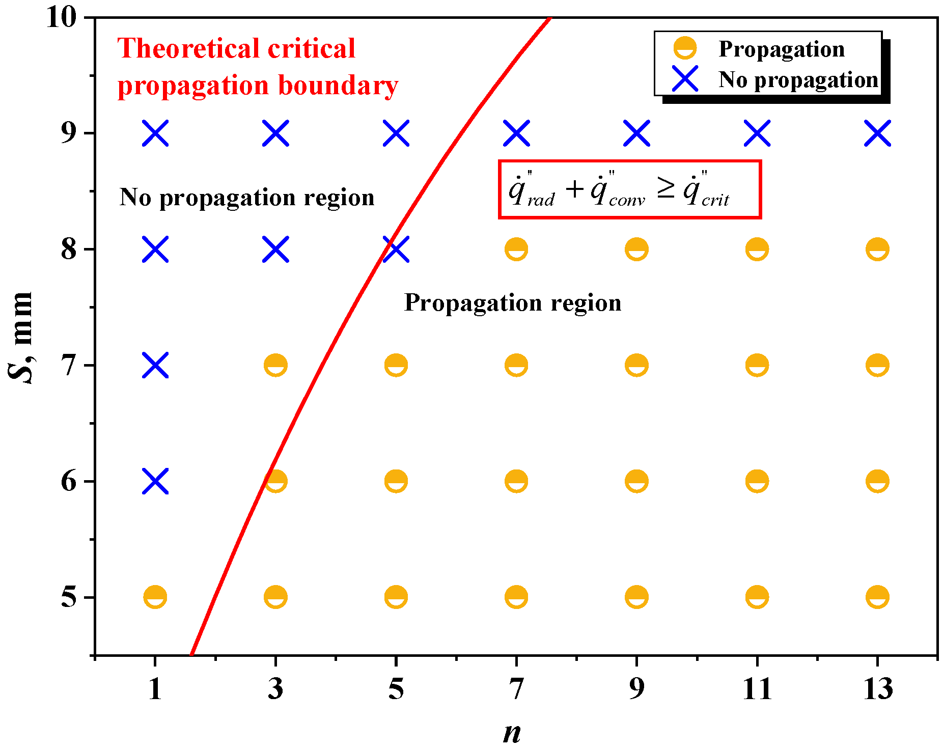
Experimental versus predicted critical flame spread boundaries are shown in Figure 18. The critical spacing for flame spread across the single-column array is 5 mm [34]. When S is ≤8 mm, the predicted critical boundary for discrete flame spread agrees well with the experimental results. When S = 9 mm, the predicted results somewhat deviate from the experimental results because in the theoretical model, the view factor and the emissivity are functions related to the flame length. However, when S = 9 mm, due to the large array spacing, the behaviors of flame merging and flame length increase did not occur, resulting in deviation. Table 2 demonstrates the input parameters that were used for the calculation.

5. Conclusions

In this study, we investigated the influence of column numbers and array spacings on the horizontal flame spread in discrete arrays under natural convection and ambient wind conditions. We discussed and analyzed flame spread characteristic parameters, including Vf, MLR, and Lf. A critical criterion for determining the flame spread process of discrete fuel under natural convection was proposed. The main conclusions are as follows:
(1)
The effects of discrete fuel distribution on flame spread behavior are similar under both natural convection and ambient wind conditions. Vf and the array width are positively correlated due to the combined effect of flame merging and air entrainment. Under natural convection, Vf decreases with increasing porosity, and the optimum porosity is 80%. The maximum porosity that can sustain the discrete flame spread process is 88.9%. However, under ambient wind, Vf increases with increasing porosity.
(2)
The MLR decreases with the increase in array spacing. There is a positive power law correlation between the MLR and the column number. By applying mass conservation principles, a predictive model for the mass loss rate was constructed. Lf increases exponentially with the rising column number of the fuel array. The power law correlation between the nondimensional flame length and the nondimensional heat release rate is revealed. It is also found that the nondimensional flame length is correlated to the array width by a power law function of L f = 427.59 W 1.6 96.19 W 0.72 .
(3)
Radiative heat transfer dominates in the flame spread process, accounting for over 68% of the total maximum heat flux. Experiments revealed the critical spacing of horizontal flame spread in discrete arrays under natural convection. We also created a heat transfer model of horizontal discrete flame spread and established a critical criterion for determining whether the process of flame spread across discrete fuel arrays can be sustained under natural convection, considering both radiative and convective heat transfer. Excellent agreement was observed between model predictions and experimental data.

Author Contributions

Conceptualization, X.Z. and S.L.; methodology, Z.W.; software, T.C.; formal analysis, X.Z. and Y.X.; investigation, Y.X.; data curation, S.L.; writing—original draft preparation, X.Z.; writing—review and editing, Y.Z. and Z.W.; supervision, Y.Z.; project administration, Z.W.; funding acquisition, Z.W. All authors have read and agreed to the published version of the manuscript.

Funding

This study is supported by the National Natural Science Foundation of Hunan Province (No. 2023JJ60169), Research Project of Hunan Vocational Institute of Safety Technology (No. AY25B001) and Scientific Research Fund of Hunan Provincial Education Department (24B0968).

Institutional Review Board Statement

Not applicable.

Informed Consent Statement

Not applicable.

Data Availability Statement

The original contributions presented in this study are included in the article. Further inquiries can be directed to the corresponding author.

Conflicts of Interest

The authors declare no conflicts of interest.

Nomenclature

Ai, AjUpper surface of fuel rods
cpSpecific heat capacity (kJ/kg K)
dRod diameter (mm)
fFuel coverage rate
Fthe view factor
FrFroude number
GrGrashof number
hConvective heat transfer coefficient (W/m2K)
HcCombustion heat of pyrolyzed gas (kJ/g)
kThermal conductivity (W/m K)
lFuel length (mm)
LfFlame length (mm)
Lf*Nondimensional flame length
m ˙ Mass loss rate (g/s)
m ˙ *Nondimensional mass loss rate
nColumn number
NQuantity of burning fuel rod
NuNusselt number
PrPrandtl number
Q ˙ Heat release rate (kW)
Q ˙ *Nondimensional heat release rate
q ˙ i n , max Heat flux received by the unburned fuel (kW/m2)
q ˙ c r i t Critical incident heat flux (kW/m2)
q ˙ r a d Radiant heat flux (kW/m2)
q ˙ c o n v Conductive heat flux (kW/m2)
qtotTotal heat flux (kW/m2)
rRow number
RaRayleigh number
SArray spacing (mm)
Sppore area of the fuel bed (mm2)
Sbtotal area of the fuel bed (mm2)
VfFlame spread rate (mm/s)
Vf,dDownward vertical flame spread rate of infinite array (mm/s)
tTime (s)
TTemperature (K)
UWind speed (mm/s)
Warray width(mm)
Greek symbols
αThermal diffusivity (m2/s)
βThermal expansion coefficient (1/K)
δLaminar boundary layer thickness (mm)
ρDensity (kg/m3)
θangle between two surfaces and their normal vectors
εSurface emissivity
ϕPorosity
vKinematic viscosity (m2/s)
σStefan–Boltzmann constant (W/m2 K4)
Subscripts
fFlame
gGas
pPyrolysis
sFuel
Ambient

References

  1. Balch, J.K.; Abatzoglou, J.T.; Joseph, M.B.; Koontz, M.J.; Mahood, A.L.; McGlinchy, J.; Cattau, M.E.; Williams, A.P. Warming weakens the night-time barrier to global fire. Nature 2022, 602, 442–448. [Google Scholar] [CrossRef] [Scilit]
  2. Miller, C.H.; Gollner, M.J. Upward flame spread over discrete fuels. Fire Saf. J. 2015, 77, 36–45. [Google Scholar] [CrossRef] [Scilit]
  3. Gollner, M.J.; Miller, C.H.; Tang, W.; Singh, A.V. The effect of flow and geometry on concurrent flame spread. Fire Saf. J. 2017, 91, 68–78. [Google Scholar] [CrossRef] [Scilit]
  4. Vogel, M.; Williams, F.A. Flame Propagation Along Matchstick Arrays. Combust. Sci. Technol. 1970, 1, 429–436. [Google Scholar] [CrossRef] [Scilit]
  5. Frankman, D.; Webb, B.W.; Butler, B.W. Time-resolved radiation and convection heat transfer in combusting discontinuous fuel beds. Combust. Sci. Technol. 2010, 182, 1391–1412. [Google Scholar] [CrossRef] [Scilit]
  6. Yedinak, K.M.; Cohen, J.D.; Forthofer, J.M.; Finney, M.A. An examination of flame shape related to convection heat transfer in deep-fuel beds. Int. J. Wildland Fire 2010, 19, 171–178. [Google Scholar] [CrossRef] [Scilit]
  7. Emmons, H.W.; Shen, T. Fire spread in paper arrays. Symp. (Int.) Combust. 1971, 13, 917–926. [Google Scholar] [CrossRef] [Scilit]
  8. Kosdon, F.; Williams, F.; Buman, C. Combustion of vertical cellulosic cylinders in air. Symp. (Int.) Combust. 1969, 12, 253–264. [Google Scholar] [CrossRef] [Scilit]
  9. He, Q.; Liu, N.; Xie, X.; Zhang, L.; Zhang, Y.; Yan, W. Experimental Study on Fire Spread over Discrete Fuel Bed-Part I: Effects of Packing Ratio. Fire Saf. J. 2021, 126, 103470. [Google Scholar] [CrossRef] [Scilit]
  10. He, Q.; Liu, N.; Xie, X.; Zhang, L.; Lei, J.; Zhang, Y.; Wu, D. Experimental study on fire spread over discrete fuel bed-Part II: Combined effects of wind and packing ratio. Fire Saf. J. 2022, 128, 103520. [Google Scholar] [CrossRef] [Scilit]
  11. Cui, W.; Liao, Y. Experimental Study of Upward Flame Spread over Discrete Thin Fuels. Fire Saf. J. 2019, 110, 102907. [Google Scholar] [CrossRef] [Scilit]
  12. Park, J.; Brucker, J.; Seballos, R.; Kwon, B.; Liao, Y.-T.T. Concurrent flame spread over discrete thin fuels. Combust. Flame 2018, 191, 116–125. [Google Scholar] [CrossRef] [Scilit]
  13. Zhao, Z.; Gorham, D.; Gollner, M.J. Flame spread through arrays of wooden dowels. In Proceedings of the 8th US National Combustion Meeting 2013, Park City, UT, USA, 19–22 May 2013; Volume 2, pp. 1483–1492. [Google Scholar]
  14. Jiang, L.; Zhao, Z.; Tang, W.; Miller, C.; Sun, J.-H.; Gollner, M.J. Flame spread and burning rates through vertical arrays of wooden dowels. Proc. Combust. Inst. 2019, 37, 3767–3774. [Google Scholar] [CrossRef] [Scilit]
  15. Bu, R.; Zhou, Y.; Fan, C.; Wang, Z. Understanding the effects of inclination angle and fuel bed width on concurrent flame spread over discrete fuel arrays. Fuel 2021, 289, 119924. [Google Scholar] [CrossRef] [Scilit]
  16. Bu, R.; Zhou, Y.; Shi, L.; Fan, C. Experimental study on combustion and flame spread characteristics in horizontal arrays of discrete fuels. Combust. Flame 2021, 225, 136–146. [Google Scholar] [CrossRef] [Scilit]
  17. Gollner, M.J.; Xie, Y.; Lee, M.; Nakamura, Y.; Rangwala, A.S. Burning behavior of vertical matchstick arrays. Combust. Sci. Technol. 2012, 184, 585–607. [Google Scholar] [CrossRef] [Scilit]
  18. Zhou, Y.; Yang, F.; Lan, S.; Yi, L. Effect of ambient wind on horizontal flame spread over discrete multi-column fuel arrays. Therm. Sci. Eng. Prog. 2024, 54, 102782. [Google Scholar] [CrossRef] [Scilit]
  19. Martins Fernandes, P.A. Fire spread prediction in shrub fuels in Portugal. For. Ecol. Manag. 2001, 144, 67–74. [Google Scholar] [CrossRef] [Scilit]
  20. Di Cristina, G.; Skowronski, N.S.; Simeoni, A.; Rangwala, A.S.; Im, S.-K. Flame spread behavior characterization of discrete fuel array under a forced flow. Proc. Combust. Inst. 2021, 38, 5109–5117. [Google Scholar] [CrossRef] [Scilit]
  21. Wolff, M.F.; Carrier, G.F.; Ffndell, F.E. Wind-Aided Fire spread Across Arrays of Discrete Fuel Elements. II. Experiment. Combust. Sci. Technol. 1991, 77, 261–289. [Google Scholar] [CrossRef] [Scilit]
  22. Di Cristina, G.; Skowronski, N.S.; Simeoni, A.; Rangwala, A.S.; Im, S.-K. Flame spread predictions over linear discrete fuel arrays using an empirical B-number model and stagnation point flow. Combust. Flame 2021, 234, 111644. [Google Scholar] [CrossRef] [Scilit]
  23. Watanabe, Y.; Torikai, H.; Ito, A. Flame spread along a thin solid randomly distributed combustible and noncombustible areas. Proc. Combust. Inst. 2011, 33, 2449–2455. [Google Scholar] [CrossRef] [Scilit]
  24. Abe, S.; Ito, A.; Torikai, H. Flame spread along a thin combustible solid with randomly distributed square pores of two different sizes. Mod. Appl. Sci. 2012, 6, 11–19. [Google Scholar] [CrossRef] [Scilit]
  25. Bhattachariee, S.; King, M.D.; Takahashi, S.; Nagumo, T.; Wakai, K. Downward flame spread over poly(methyl)methacrylate. Proc. Combust. Inst. 2000, 28, 2891–2897. [Google Scholar] [CrossRef] [Scilit]
  26. Hostikka, S.; Matala, A. Pyrolysis Model for Predicting the Heat Release Rate of Birch Wood. Combust. Sci. Technol. 2017, 189, 1373–1393. [Google Scholar] [CrossRef] [Scilit]
  27. Putnam, A.; Speich, C. A model study of the interaction of multiple turbulent diffusion flames. Symp. (Int.) Combust. 1963, 9, 867–877. [Google Scholar] [CrossRef] [Scilit]
  28. Quintiere, J.; Grove, B. A unified analysis for fire plumes. Symp. (Int.) Combust. 1998, 27, 2757–2766. [Google Scholar] [CrossRef] [Scilit]
  29. Sugawa, O.; Takahashi, W. Flame height behavior from multi-fire sources. Fire Mater. 1993, 17, 111–117. [Google Scholar] [CrossRef] [Scilit]
  30. Delichatsios, M.A. A Correlation for the Flame Height in “Group” Fires. Fire Sci. Technol. 2007, 26, 1–8. [Google Scholar] [CrossRef] [Scilit]
  31. Drysdale, D. An Introduction to Fire Dynamics; Wiley: Hoboken, NJ, USA, 2011. [Google Scholar]
  32. Finney, M.A.; Mcallister, S.S. A review of fire interactions and mass fires. J. Combust. 2011, 2011, 548328. [Google Scholar] [CrossRef] [Scilit]
  33. Deverall, L.I.; Lai, W. A criterion for thermal ignition of cellulosic materials. Combust. Flame 1969, 13, 8–12. [Google Scholar] [CrossRef] [Scilit]
  34. Bu, R.; Shi, L.; Zhou, Y. Identifying the criterion for discrete flame spread over single-row birch rods. Fire Saf. J. 2020, 120, 103116. [Google Scholar] [CrossRef] [Scilit]
  35. Rossi, J.-L.; Chetehouna, K.; Collin, A.; Moretti, B.; Balbi, J.-H. Simplified flame models and prediction of the thermal radiation emitted by a flame front in an outdoor fire. Combust. Sci. Technol. 2010, 182, 1457–1477. [Google Scholar] [CrossRef] [Scilit]
  36. Quintiere, J.G. Fundamentals of Fire Phenomena; Wiley: Hoboken, NJ, USA, 2006. [Google Scholar]
  37. Liu, N.; Wu, J.; Chen, H.; Xie, X.; Zhang, L.; Yao, B.; Zhu, J.; Shan, Y. Effect of slope on spread of a linear flame front over a pine needle fuel bed: Experiments and modelling. Int. J. Wildland Fire 2014, 23, 1087–1096. [Google Scholar] [CrossRef] [Scilit]
  38. Janssens, M.L. A thermal model for piloted ignition of wood including thermophysical properties. Fire Saf. Sci. 1991, 3, 167–176. [Google Scholar] [CrossRef] [Scilit]
  39. Holman, J.P.; Rao, P.N. Heat Transfer, 10th ed.; McGraw Hill: New York, NY, USA, 2010. [Google Scholar]
  40. Hwang, C.C.; Xie, Y. Flame propagation along matchstick arrays on inclined base boards. Combust. Sci. Technol. 1984, 42, 1–12. [Google Scholar] [CrossRef] [Scilit]
Figure 1. Experimental setup for discrete flame spread.
Fire 09 00054 g001
Figure 2. Combustion wind tunnel system.
Fire 09 00054 g002
Figure 3. Flame spread process of single-column birch rods: (a) nature convection (S = 5 mm); (b) ambient wind (S = 9 mm).
Fire 09 00054 g003
Figure 4. Flame length modulation by array spacing (n = 1): (a) nature convection; (b) ambient wind.
Fire 09 00054 g004
Figure 5. Flame length modulation by array width (S = 5 mm): (a) nature convection; (b) ambient wind.
Fire 09 00054 g005
Figure 6. Front view of the discrete flame spreading through discrete rod arrays (S = 7 mm, n = 13, U = 0 m/s).
Fire 09 00054 g006
Figure 7. Dependency of flame spread rate on column number.
Fire 09 00054 g007
Figure 8. Dependency of discrete flame spread rate on porosity.
Fire 09 00054 g008
Figure 9. Dependency of flame spread rate on array width.
Fire 09 00054 g009
Figure 10. Dependency of MLR on discrete fuel distribution: (a) column number; (b) array spacing.
Fire 09 00054 g010
Figure 11. Dependency of MLR on array width.
Fire 09 00054 g011
Figure 12. Relationship between nondimensional MLR and f.
Fire 09 00054 g012
Figure 13. Comparison between the experimental and calculated MLR values.
Fire 09 00054 g013
Figure 14. Dependency of flame length on discrete fuel distribution: (a) array spacing; (b) column number.
Fire 09 00054 g014
Figure 15. Dependency of L f * on (a) Q ˙ * and (b) W [16,18].
Fire 09 00054 g015
Figure 16. Maximum heat flux with different array spacings and column numbers.
Fire 09 00054 g016
Figure 17. Heat transfer model of discrete flame spread of discrete fuel arrays.
Fire 09 00054 g017
Figure 18. Comparison of experimental and predicted critical flame spread boundaries.
Fire 09 00054 g018
Table 1. Experimental conditions.
U (m/s)S (mm)n
Natural convection05, 6, 7, 8, 91, 3, 5, 7, 9, 11, 13
Ambient wind0.59, 11, 13, 15, 17, 191, 5, 9, 13
Table 2. The input parameters used in the calculation.
SymbolParameterValueSource
ρ s Fuel density631.56 kg/m3measured in the experiment
kgThermal conductivity of air59.6 × 10−3 W/(mK)[31]
T Ambient temperature300 Kmeasured in the experiment
T f Flame temperature1400 K[40]
T s Surface temperature300 Kmeasured in the experiment
T p Pyrolysis temperature573 K[38]
PrPrandtl number0.725[31]
βThermal expansion coefficient1.18 × 10−3 K−1[31]
ν1Kinematic viscosity9.38 × 10−5 m2/s[31]
ν2Kinematic viscosity1.2 × 10−4 m2/s[31]
αgThermal diffusivity1.31 × 10−4 m2/s[31]
q ˙ c r i t Critical ignition heat flux13.3 kW/m2[38]
Disclaimer/Publisher’s Note: The statements, opinions and data contained in all publications are solely those of the individual author(s) and contributor(s) and not of MDPI and/or the editor(s). MDPI and/or the editor(s) disclaim responsibility for any injury to people or property resulting from any ideas, methods, instructions or products referred to in the content.