


Abstract
This study involved a numerical parametric assessment of reinforced concrete (RC) T-beams strengthened with bonded steel wire ropes (SWRs), with the aim of evaluating the effectiveness of this strengthening system in terms of improving flexural performance. Since extensive experimental investigations are costly and time-consuming, a three-dimensional finite element model was constructed to represent the structural response of strengthened RC T-beams. This numerical model was verified using earlier experimental data to ensure its predictive capability for the flexural behavior of strengthened members. Following validation, the model was applied in a comprehensive parametric study to examine the effects of key design variables on structural performance. These variables included the SWR diameter, the compressive strength of the bonding mortar, and the strength of the bonding material. Their effects on load-carrying capacity, stiffness, deformation behavior, and energy absorption were systematically evaluated. The results indicated that SWR diameter was the dominant parameter, increasing ultimate load up to 1.93 times, with stiffness and energy absorption reaching 1.48 and 1.74 times those of the control beam, respectively. In contrast, higher concrete compressive strength provided moderate gains, with load capacity and stiffness increasing by up to 16% and 21%, while having a limited influence on ductility. Variations in bonding material strength showed minimal impact and negligible changes in stiffness. Strength and stiffness enhancements were accompanied by reduced ductility, indicating a trade-off between capacity and deformation. These findings confirmed that SWR efficiency was governed primarily by reinforcement size, while other parameters exhibited diminishing returns beyond threshold levels.
1. Introduction
The durability and structural reliability of civil infrastructure remain central concerns in structural engineering, particularly for load-bearing elements that have been in service for extended periods. Many existing structural components were originally designed for earlier service conditions and may now be subjected to increased operational demands, environmental exposure, and cumulative damage effects. Processes such as material aging, cyclic loading, and aggressive environmental conditions can progressively degrade mechanical performance, ultimately reducing load-carrying capacity and compromising serviceability [1,2,3,4]. Moreover, the continual evolution of structural design standards requires many existing structures to be reassessed against more stringent modern code provisions. As a result, rehabilitation and strengthening of aging structural members have become essential strategies for maintaining structural safety and extending service life. An effective strengthening solution must enhance flexural resistance while preserving constructability, economic feasibility, and compatibility with the existing structural system.
Of the various structural materials used in infrastructure, reinforced concrete (RC) is particularly prone to both gradual deterioration and sudden damage events. Extreme hazards such as earthquakes, fire exposure, and severe environmental conditions can induce substantial structural distress, accelerating the degradation of concrete members [5,6,7]. In addition, performance deficiencies may arise from design limitations, construction-related imperfections, long-term material degradation, or service loads that exceed the original design assumptions [8,9,10,11,12]. A combination of these factors can significantly reduce the reliability and resilience of existing structures. As a result, developing effective strengthening and rehabilitation techniques has become an important focus in modern structural engineering, since well-designed retrofit strategies can restore structural capacity, reduce vulnerability to future hazards, and improve the long-term performance of aging infrastructure.
A widely adopted strategy for upgrading existing structural members involves externally bonded reinforcement systems, in which additional materials are attached to the surface of the structural element to improve its mechanical performance [13,14,15,16,17]. Among available materials, fiber-reinforced polymers (FRPs) have been extensively adopted due to their lightweight nature, high strength, and excellent corrosion resistance [18,19,20,21,22,23,24,25,26,27], making them suitable for retrofit applications with minimal added weight. Previous studies confirm their effectiveness in improving shear capacity, deformation, and load–displacement response, as well as enhancing strength and stiffness when combined with high-strength concrete (HSC) jacketing [28,29,30]. Despite these advantages, FRP systems present practical limitations related to epoxy bonding, such as premature debonding, performance degradation at elevated temperatures, high material costs, and challenges under unfavorable installation conditions [31,32]. These constraints have driven the exploration of alternative strengthening materials that can overcome such drawbacks while maintaining structural efficiency.
Steel wire rope (SWR) has emerged as a promising strengthening material due to its high tensile strength, flexibility, and strong resistance to torsional and bending actions while maintaining relatively low weight [33]. Its effectiveness in strengthening RC members has been widely investigated in recent years [34,35,36,37,38,39], demonstrating its potential as a viable alternative to conventional reinforcement systems. Wu et al. [40,41] examined the flexural performance of prestressed RC beams reinforced with SWRs and reported significant improvements in load-carrying capacity and cracking behavior. In addition, studies on SWR-confined concrete columns revealed enhanced confinement effects and ductility [42], contributing to the development of design provisions incorporated into the JGJ/T325-2014 guidelines [43]. Further applications have extended SWR systems to various structural elements, including hollow-core slabs and stone members, where prestressed SWRs improved cracking resistance and flexural performance through effective composite interaction [44,45].
Haryanto et al. [46] further extended SWR applications to RC T-beams under varying prestressing levels, reporting substantial improvements in cracking, yield, and ultimate loads. Subsequent numerical studies confirmed the reliability of the predictive model, with differences of less than 10% between experimental and simulated results [47]. Similarly, Atmajayanti et al. [48] demonstrated notable gains in strength, stiffness, and energy absorption using bonded SWR systems, with strong agreement between analytical and experimental results. Despite these advances, several aspects of SWR-based strengthening remain insufficiently understood, particularly regarding the influence of key material and geometric parameters on structural performance. Given that experimental investigations are costly and time-consuming [49,50,51], validated analytical and numerical approaches are required to systematically evaluate these factors and support the development of reliable design recommendations.
To address this need, the present study extends the previous experimental work of Atmajayanti et al. [48] through a comprehensive numerical parametric investigation of RC T-beams retrofitted with bonded SWR systems. The study begins with the development of a three-dimensional finite element model, which is validated against the experimental results reported in the same research program [48]. The validated model is then used to study a systematic parametric study examining the influence of variables, including the diameter of the wire ropes, the concrete compressive strength, and the bonding material strength. The effects of these parameters on the flexural capacity, stiffness, deformation behavior, and energy dissipation of the beams are evaluated to clarify the governing strengthening mechanisms. The results offer improved understanding of the behavior of SWR-strengthened RC members and provide a numerical framework for performance evaluation. The outcomes are expected to assist in developing more effective strengthening strategies for RC structures.
2. Summary of the Experimental Program
2.1. Specimen Geometry and Reinforcement Configuration
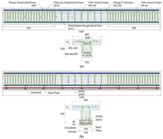
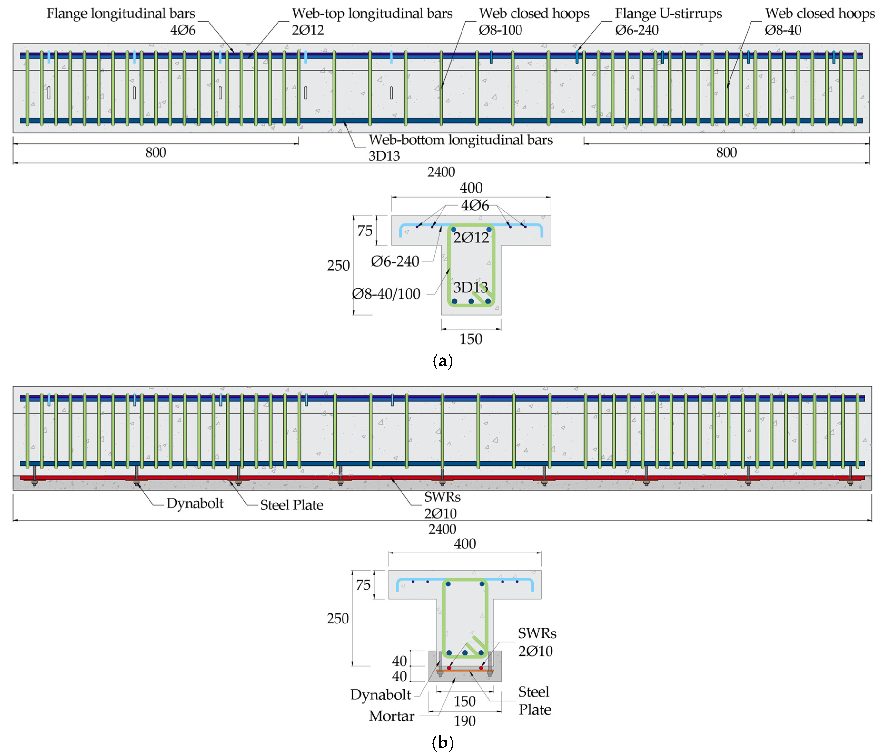
The specimen was designed to ensure flexural failure under four-point bending, as shown in Figure 1. RC T-beams were prepared with longitudinal reinforcement consisting of three Ø13 mm deformed bars at the bottom of the web to resist tensile stresses and two Ø12 mm bars at the top. Additional flange reinforcement was provided using four Ø6 mm bars to enhance compressive capacity.
Figure 1.
Geometry and reinforcement configuration of the T-beam specimens (units in mm) [48]: (a) control beam (BC); (b) SWR-strengthened beam (BS).
The flange width was set at 400 mm based on standard design criteria, where the effective width is governed by the minimum of L/4, the beam spacing, or the slab width [52]. For the given span, L/4 equals 600 mm, indicating that the selected width represents a conservative and practical configuration while maintaining sufficient compression capacity. Shear reinforcement was provided using two-legged Ø8 mm stirrups spaced at 40 mm along the shear span. The experimental program included two specimens: an unstrengthened control beam (BC) and a strengthened beam (BS) retrofitted with two 10 mm diameter SWRs bonded along the soffit of the web over the full span.
2.2. Strengthening Application Procedure
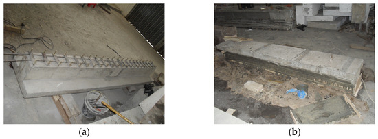
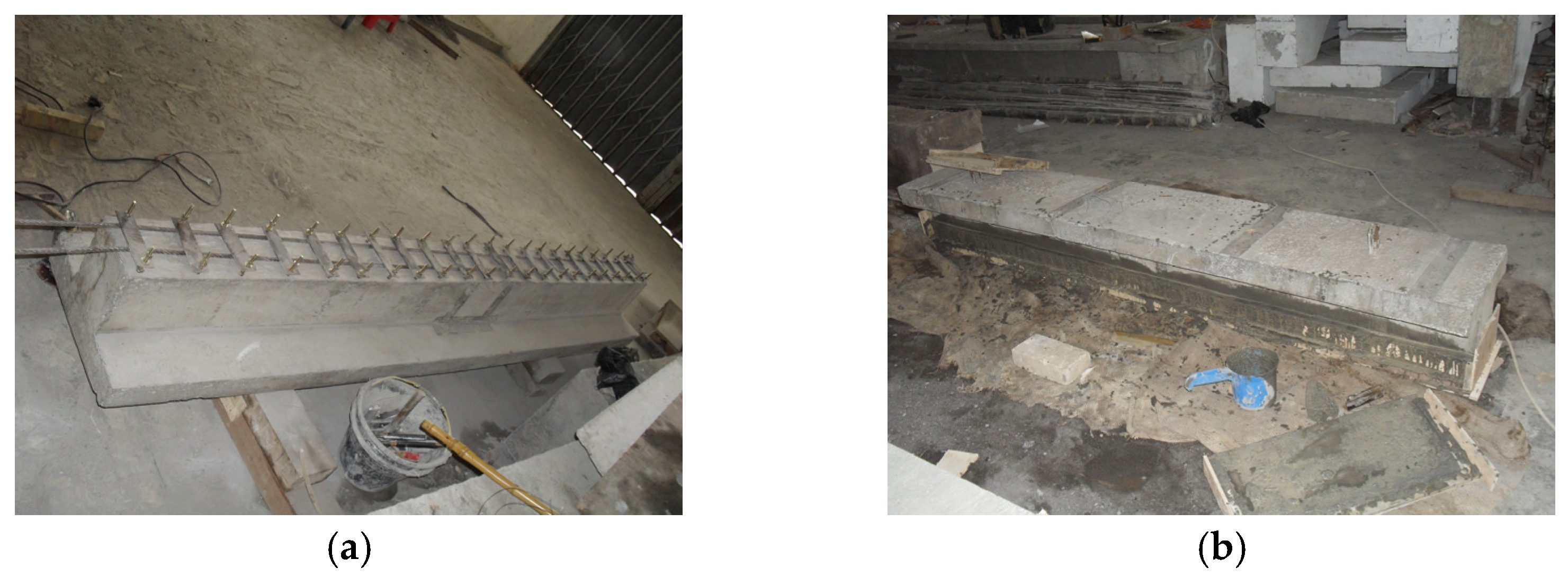
The strengthening application began by locating the internal reinforcement in the RC beam using a non-destructive rebar scanner to avoid interference with the existing steel bars. Drilling points were then marked, and boreholes approximately 60 mm deep were prepared to accommodate the anchorage system. The holes were cleaned with compressed air to ensure adequate bonding conditions. A chemical adhesive was injected into the cavities to promote effective bonding between the anchorage elements and the surrounding concrete. The anchorage system, composed of a steel plate and a dynabolt, was then placed and secured by tightening the dynabolt at the upper end of the steel plate, as presented in Figure 2a. Finally, a mortar-based adhesive was applied to attach the SWRs to the concrete surface, completing the strengthening procedure (Figure 2b).
Figure 2.
Installation of the SWR strengthening system: (a) anchoring of SWRs using steel plates and dynabolts; (b) application of the mortar adhesive.
2.3. Test Setup and Instrumentation Layout
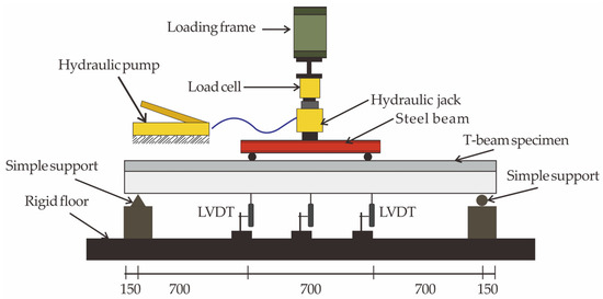
The loading setup and instrumentation are illustrated in Figure 3. Each beam was tested under four-point bending using a symmetric vertical load applied through a steel spreader beam connected to a 100-ton electro-hydraulic actuator.
Figure 3.
Schematic diagram of the experimental setup for the four-point bending test [48].
This configuration created a constant moment region of approximately 700 mm at mid-span. The applied load was transmitted through a load cell and a steel distribution beam to the simply supported specimen, with loading controlled at a constant rate of 200 N/s. Crack initiation and propagation were continuously monitored and marked on the beam surface for documentation. Structural response was evaluated using a calibrated pressure transducer to measure the applied load, while three LVDTs positioned at the left loading point, mid-span, and right loading point recorded vertical displacements. Crack development was further documented using a crack observation viewer, allowing detailed assessment of cracking behavior throughout the test.
3. Finite Element Modeling Approach
3.1. Constitutive Models
3.1.1. Representation of Concrete Behavior
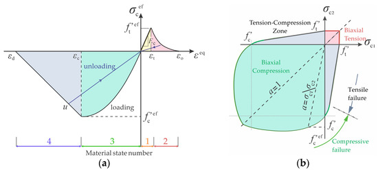
The numerical analysis was performed using Advanced Tool for Engineering Nonlinear Analysis (ATENA) (V.2023.0.0.22492), a widely used platform for simulating the nonlinear behavior of RC structures [53,54,55,56]. The concrete constitutive model (Figure 4a) describes the uniaxial stress–strain response through four stages representing progressive damage and softening. In this study, the compressive behavior was defined using the empirical formulation from the CEB–FIP Model Code [57], applicable to both normal concrete and HSC, while a linear softening branch was adopted to capture post-peak degradation and energy dissipation typical of quasi-brittle materials [58].
Figure 4.
Concrete constitutive relationships adopted in the model [53]: (a) uniaxial stress–strain curve; (b) biaxial failure envelope.
The biaxial response was expressed through the relationship between the effective compressive stress and equivalent strain , where the latter is obtained by normalizing the uniaxial stress component with respect to the corresponding elastic modulus . This formulation incorporates loading history effects, enabling path-dependent response simulation. Figure 4b, adapted from Kupfer et al. [59], illustrates the influence of biaxial stress states on strength and defines the multiaxial failure envelope.
For the numerical model developed here, the behavior of concrete was represented using the CC3DnonLinCementitious2 material formulation offered in ATENA, based on eight-node solid elements. This formulation is suitable for nonlinear analysis of cementitious materials, enabling simulation of stiffness degradation during the pre-peak hardening stage while continuously updating the material response throughout loading. The model requires key input parameters, including compressive strength, tensile strength, elastic modulus, Poisson’s ratio, fracture energy, and critical compressive displacement, as summarized in Table 1.
Table 1.
Material parameters of the concrete used in the FE model.
The compressive strength was obtained from experimental results reported in [48] following ASTM C39/C39M-21 [60], while the remaining parameters were derived from empirical relationships and established design provisions [53]. To address mesh sensitivity associated with the smeared-crack approach, crack-band regularization based on fracture energy was adopted. Although no explicit mesh-refinement study was conducted, the selected mesh density ensured numerical stability, computational efficiency, and accurate representation of the global load–deformation response.
3.1.2. Modeling of Steel Materials
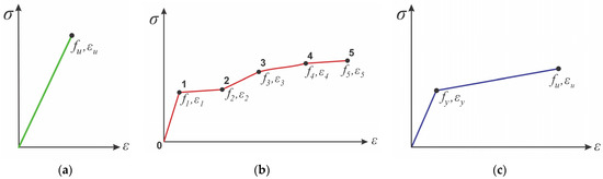
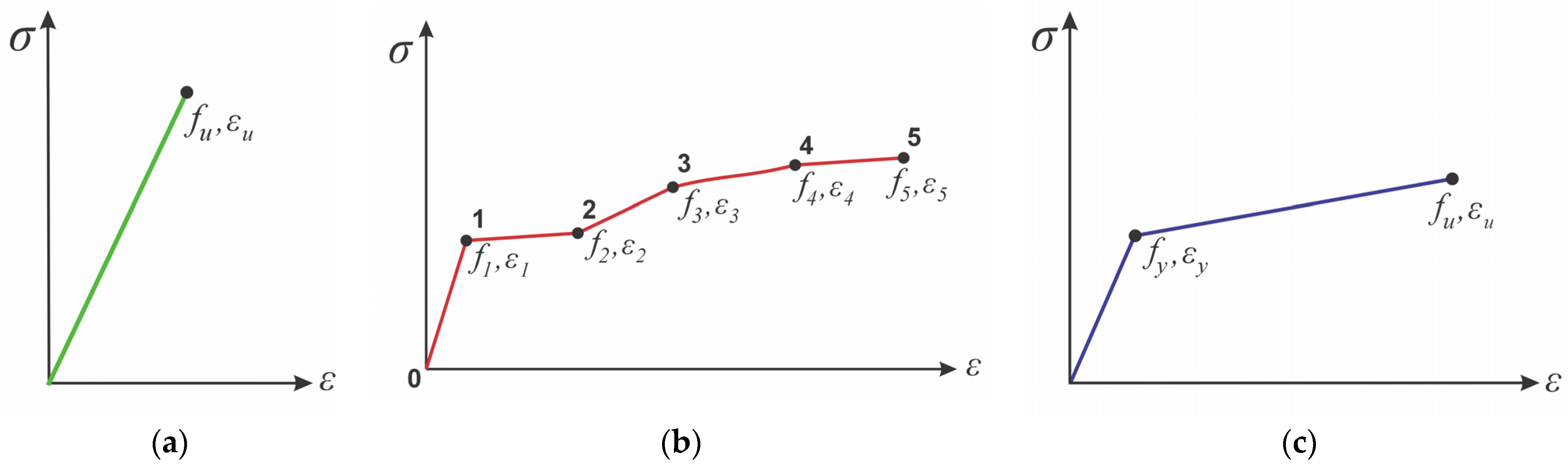
The longitudinal steel reinforcement and SWRs were modeled using two-node CCReinforcement elements, in which compressive resistance is neglected. This assumption is appropriate for materials with low bending stiffness, such as SWRs, where compressive forces may induce premature buckling and thus contribute minimally to structural response. The SWRs were assumed to exhibit linear elastic behavior in tension up to failure (Figure 5a). In contrast, the longitudinal reinforcement was defined using a multi-linear stress–strain model capturing the elastic region, yield plateau, strain hardening, and fracture (Figure 5b). This formulation is governed by four user-defined points that control transitions between behavioral stages. The anchorage system, consisting of steel plates and dynabolts, was not explicitly modeled; instead, its effect was incorporated through a perfect-bond assumption at the mortar–concrete interface, allowing representation of global composite action without simulating local connector behavior.
Figure 5.
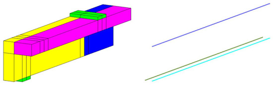
Stress–strain relationships used for steel materials: (a) linear elastic response of SWR; (b) multi-linear model for longitudinal reinforcement [53]; (c) bilinear stress–strain relationship with strain hardening for stirrups [53].
Concrete regions with transverse reinforcement were modeled using eight-node CCCombinedMaterial elements, enabling interaction between concrete and smeared reinforcement within a unified formulation. Stirrups were represented by a bilinear stress–strain model with strain hardening (Figure 5c), allowing simulation of cracking, shear retention, and post-cracking stiffness within a continuum framework. Crack-band regularization based on fracture energy ensured consistent crack treatment across the mesh. However, localized effects such as mesh dependency, crack localization, and shear-transfer mechanisms were not explicitly addressed and remain limitations requiring future mesh-sensitivity studies.
The support and loading plates were modeled as 20 mm thick solid steel components using the CC3DElastIsotropic formulation, with a linear elastic response defined by an elastic modulus of 200 GPa, assuming elastic behavior to ensure efficient load transfer without introducing unnecessary nonlinear effects. The mechanical properties of steel reinforcement and SWRs were obtained from tensile tests following ASTM A370-18 [61], and the corresponding input parameters are summarized in Table 2.
Table 2.
The input parameters used in the FE model for steel materials [48].
3.2. Geometric Modeling and Discretization
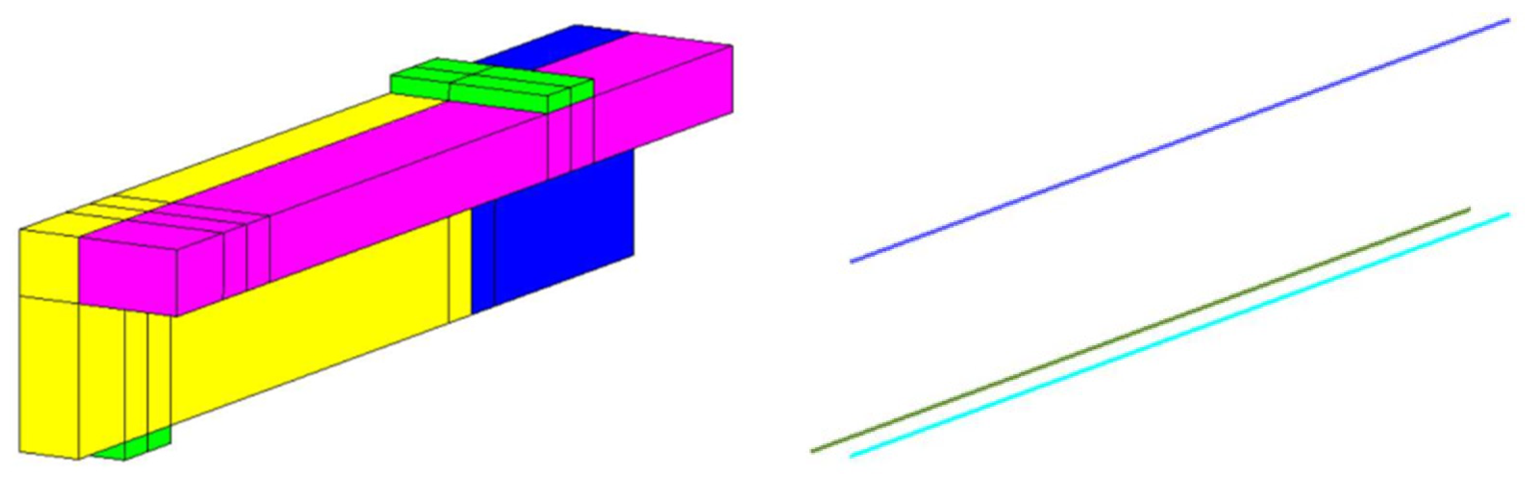
The FE model was constructed to replicate the experimental conditions using the same geometric dimensions, material properties, and boundary constraints. To improve computational efficiency while maintaining predictive reliability, only one-quarter of the beam was modeled by exploiting symmetry in geometry, reinforcement, and loading (Figure 6). This simplification is appropriate for monotonic loading, where the global response is predominantly symmetric. However, localized nonlinear effects, such as crack initiation and damage localization, may still produce asymmetric behavior that is not fully captured by the reduced model. Thus, the quarter-beam approach represents the global load–deformation response, while the influence of localized asymmetry remains a limitation of the modeling strategy.
Figure 6.
Geometric representation of the FE model, with color-coded regions indicating the different material components. The left figure: light green represents the steel plate, yellow indicates concrete containing Ø8-40 stirrups in the web, pink represents concrete with Ø8-40 stirrups in the flange, dark blue corresponds to concrete with Ø8-100 stirrups in the web. The right figure: light blue indicates full Ø13 longitudinal reinforcement, dark green denotes half Ø13 longitudinal reinforcement, and purple represents full Ø12 reinforcement.
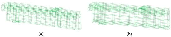
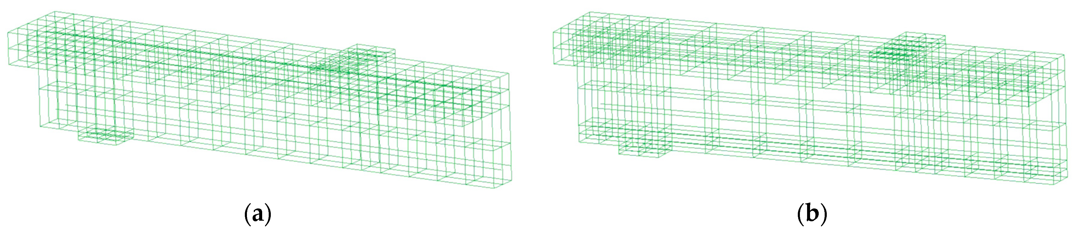
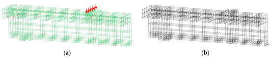
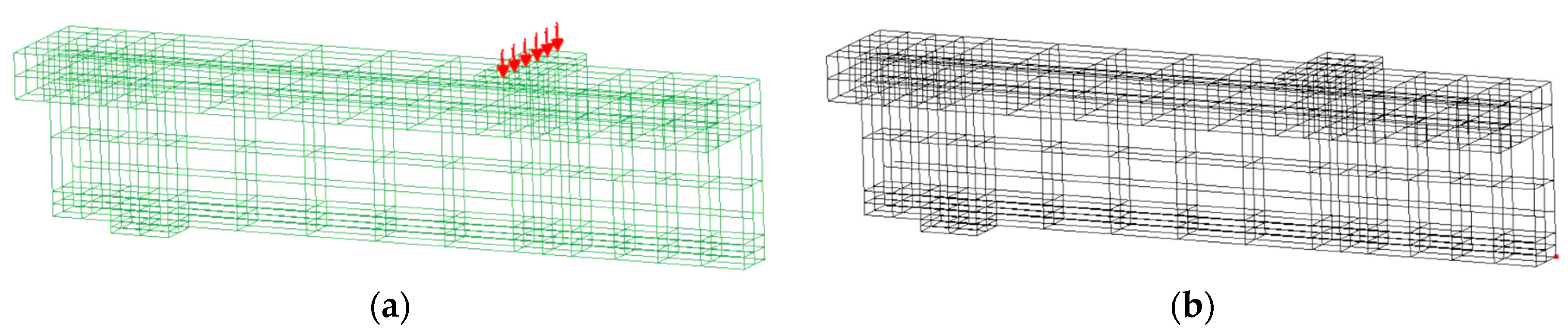
The FE model was discretized using a structured mesh with regular segmentation along the x-, y-, and z-directions. The element size was selected through geometric partitioning to balance numerical accuracy and computational efficiency, consistent with the findings of Zheng et al. [62], who reported limited accuracy gains from excessive mesh refinement. This mesh was therefore considered sufficient to capture stress distribution and cracking in critical regions without unnecessary computational cost. As shown in Figure 7, the control beam (BC) was modeled with five reinforcement elements and 261 hexahedral solid elements. Meanwhile, the strengthened beam (BS) included an additional SWR element, resulting in six reinforcement elements and 292 solid elements. The adopted mesh densities adequately reproduced the global flexural response and failure behavior. Although no specific mesh convergence assessment was performed, the smeared-crack model with fracture-energy regularization in ATENA reduces the sensitivity of the global response to mesh size, even though local cracking features were not explicitly evaluated.
Figure 7.
FE discretization adopted for the beam models: (a) mesh for the control specimen; (b) mesh for the SWR-strengthened specimen.
The numerical model adopted a perfect-bond condition at all material interfaces to simplify the formulation while preserving the global structural response. This assumption is supported by experimental observations reported in [48], where mechanical anchorage and bonding agents prevented interface slip or debonding from governing failure under monotonic loading. Accordingly, explicit interface models such as cohesive or bond–slip elements were not included, and composite action was represented by full displacement compatibility across interfaces. While this simplification enables efficient simulation of overall load–deformation behavior, it may slightly overestimate stiffness, increase peak load, and smooth the post-peak response. Nevertheless, for systems with adequate anchorage provided by steel plates and dynabolts, the influence of interface slip on ultimate flexural capacity is expected to be limited. Therefore, the results are interpreted at the structural level, while future studies incorporating bond–slip models are recommended to evaluate interfacial effects more rigorously.
3.3. Boundary Conditions and Output Response Monitoring
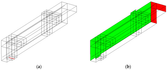
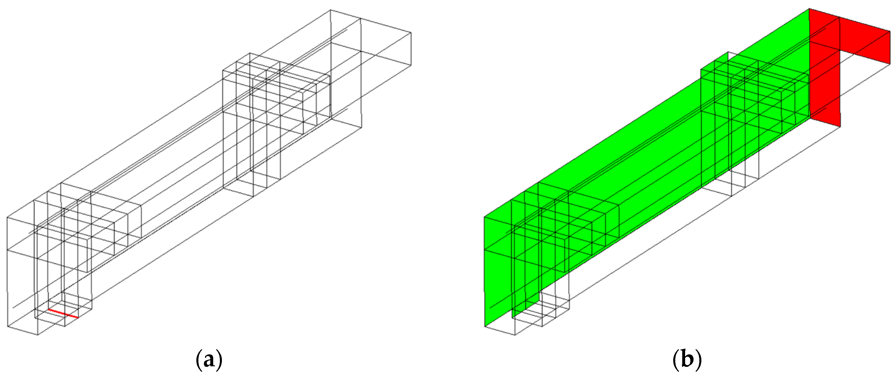
Boundary conditions were assigned to replicate the experimental supports, eliminate rigid-body motion, and preserve the beam’s flexural behavior. Vertical displacement at the supports was restrained along the centerline of the steel bearing plate using the Constraint for Line function (Figure 8a), preventing vertical movement while allowing rotational freedom. For the quarter-beam model, symmetry was imposed using the Constraint for Surface function (Figure 8b), ensuring normal displacement compatibility across the symmetry planes while permitting in-plane deformation and rotation. At the mid-span section, translational movement was restricted only in the x- and z-directions to maintain symmetry without introducing artificial rotational constraints. This approach enabled the reduced model to accurately reproduce the global response of the full beam while avoiding unintended stiffness effects.
Figure 8.
Boundary condition implementation in the FE model: (a) line constraint applied along the support axis, shown by the red line; (b) surface constraint used to enforce symmetry, shown by the green color for the constrained surface in the x-direction and the red color for the constrained surface in the z-direction.
Monitoring points were defined in the FE model to capture the nonlinear structural response of the beams. As shown in Figure 9a, the applied load was introduced through the loading plate, and the corresponding vertical reaction force was recorded to quantify the external load. Beam deflection was measured at the mid-span on the lower surface, as illustrated in Figure 9b, enabling determination of the maximum displacement. This setup follows the experimental scheme, where load and mid-span displacement define the global load–deflection behavior. Loading was applied using displacement control by incrementally imposing vertical displacement at the loading plate. A step size of 0.1 mm was adopted to ensure numerical stability and enable accurate tracing of the full nonlinear response, including stiffness degradation, crack propagation, and ultimate failure.
Figure 9.
Response measurement in the FE model: (a) loading configuration at the loading plate, where the red arrows indicate the applied loading location; (b) mid-span deflection location on the beam, where the red dot indicates the displacement monitoring point.
4. Results and Discussion
4.1. Overview of Experimental Observations
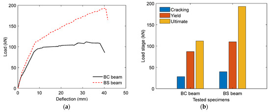
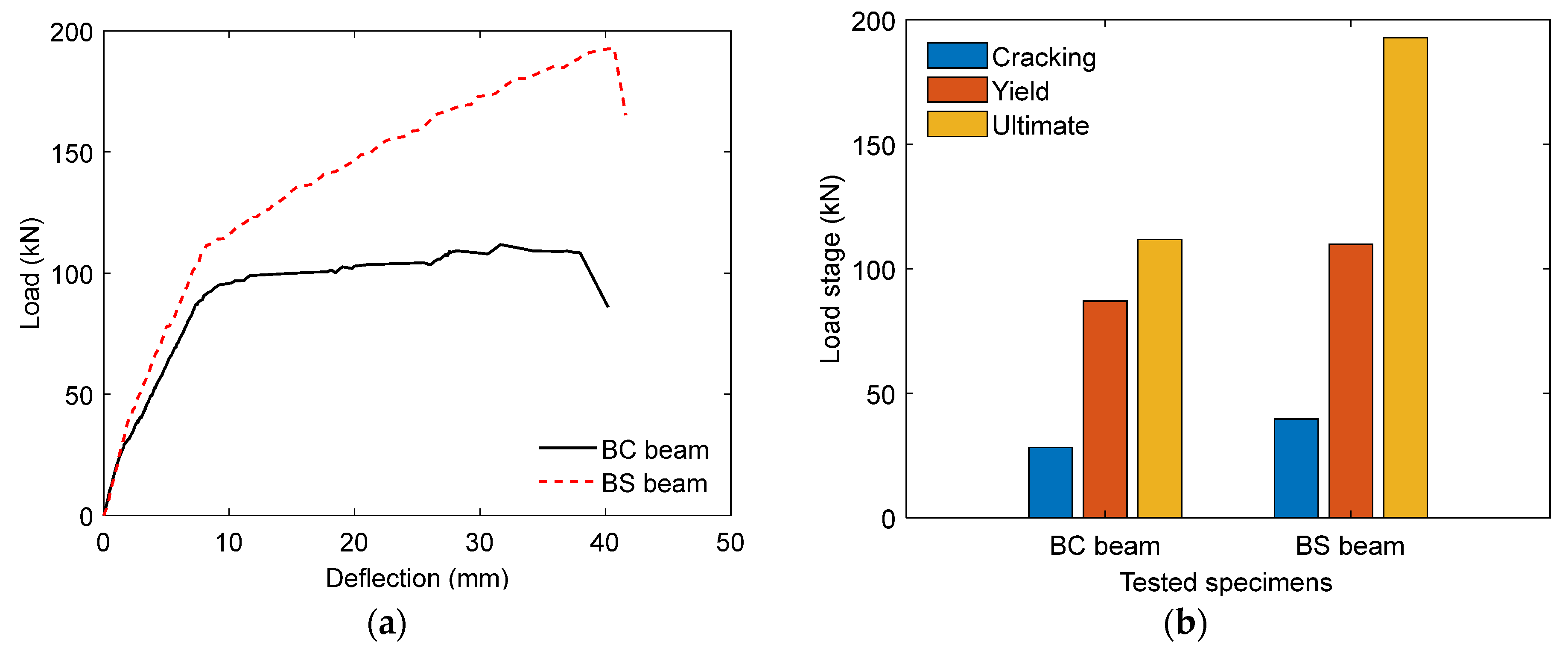
Figure 10a shows the load–deflection response of the beams, which follows a trilinear relationship representing the elastic, cracking, and post-yield stages, consistent with Atmajayanti et al. [48]. The initial stage reflects elastic behavior before crack initiation, followed by stiffness degradation as cracks propagate and stresses are transferred to the reinforcement until yielding. The final stage is characterized by reduced stiffness and plastic deformation prior to failure. Compared with the control beam (BC), the strengthened beam (BS) exhibited greater mid-span deflections, increasing by approximately 24% at crack initiation, 8% at yield, and 29% at ultimate load, indicating enhanced ductility and energy absorption. As shown in Figure 10b, the application of bonded SWRs significantly improved flexural performance, increasing crack initiation, yield, and ultimate loads by about 40%, 26%, and 72%, respectively. These gains are attributed to the additional tensile resistance provided by SWRs, which improve stress distribution and delay crack propagation.
Figure 10.
Experimental flexural responses of the beams: (a) load–deflection curves [48]; (b) comparison of characteristic load values.
4.2. Validation of the FE Model
The validation of the developed FE model in this study focuses on previously reported related experimental findings [48]. Additional RC beam cases, particularly those strengthened in the negative moment region using the same strategy, are available in the study reported by Haryanto et al. [47].
4.2.1. Unstrengthened Control Beam (BC)
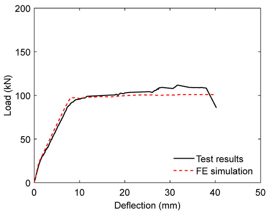
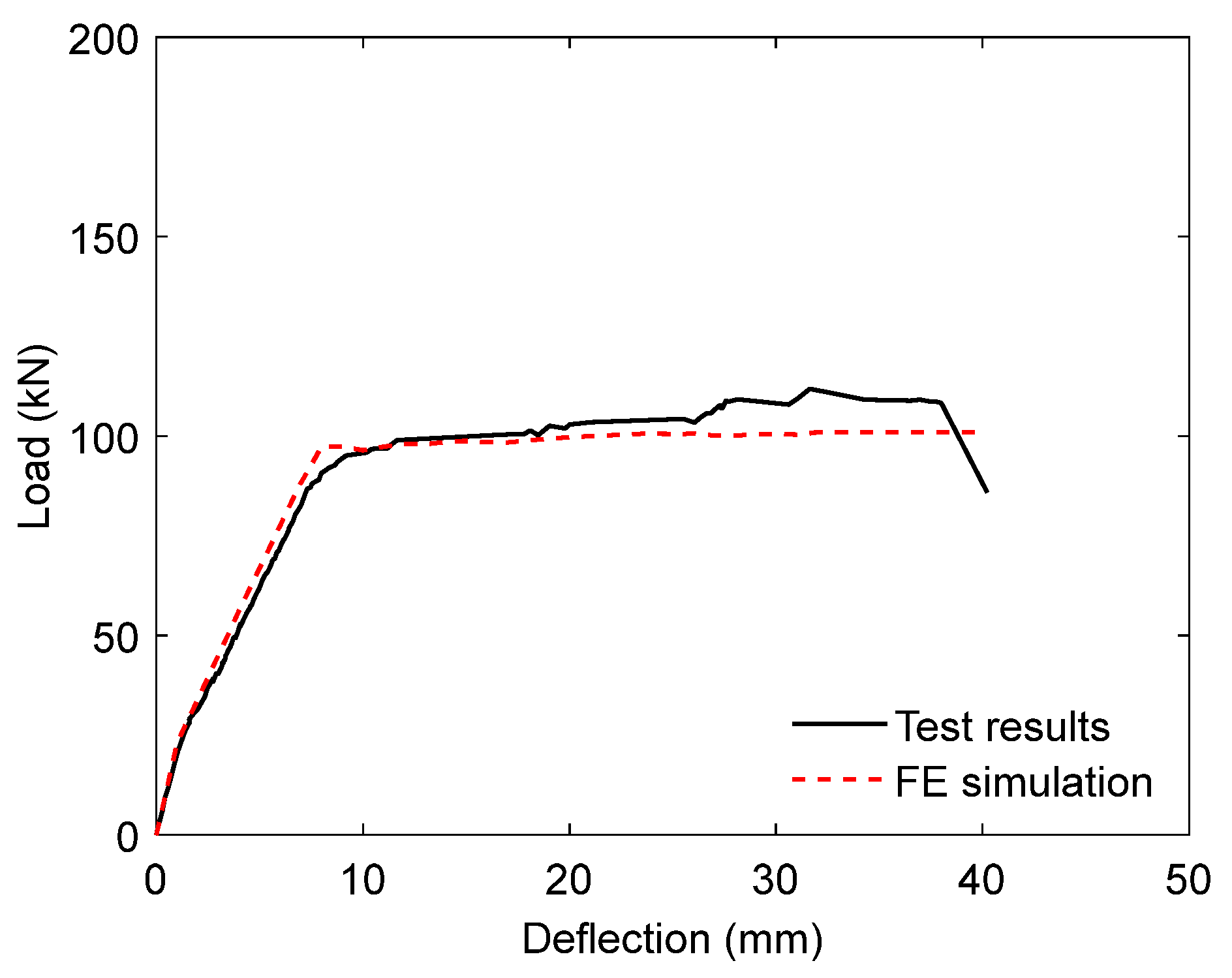
Figure 11 compares the load–deflection response of the unstrengthened control beam (BC) obtained experimentally with that predicted by the FE model. The numerical prediction follows the experimental curve with generally good agreement throughout the loading history, reproducing the main behavioral stages of the beam, including the initial linear elastic response, the progressive reduction in stiffness associated with crack development, and the post-yield response prior to failure. A minor overestimation of observed load appears in the initial stage of loading, and the predicted peak load is slightly lower than the measured experimental value. Despite these differences, the FE simulation reproduces the overall shape of the load–deflection curve and the associated stiffness development with good fidelity. This agreement demonstrates that the proposed FE model provides an adequate representation of the flexural response of the unstrengthened RC T-beam.
Figure 11.
Load–deflection curves for the unstrengthened control beam (BC) obtained from test results [48] and FE simulation.
To assess the prediction accuracy quantitatively, the normalized mean squared error (NMSE) was computed from load data extracted at displacement increments of 2.00 mm, taking the experimental result as the reference dataset. The BC specimen yielded an NMSE value of 0.005, indicating minimal deviation between the simulated and measured responses and confirming that the model can reproduce the overall load–deflection behavior with high accuracy. A further comparison was conducted using several key response parameters obtained from both the experimental results and numerical simulation, as shown in Table 3.
Table 3.
Comparison of the flexural response characteristics of the BC beam obtained from test results and FE simulation.
The model estimated an ultimate load of 100.93 kN, reasonably close to the experimental value of 111.80 kN, and a predicted failure deflection of 40.00 mm, which agrees well with the measured value of 40.23 mm. The model also reproduced other mechanical characteristics with good accuracy. The predicted stiffness and energy absorption were slightly lower than the experimental values, but the same trend in the response was evident. Similarly, the calculated value for the ductility index of 5.18 compares well with the experimentally obtained value of 5.40, demonstrating that the model can reasonably capture the deformation capacity beyond yielding. The overall average for the numerical-to-experimental ratio of the evaluated parameters was 0.94, indicating that the FE model shows a reliable representation of the fundamental flexural behavior of the control beam and can be used with confidence in further numerical investigations.
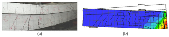
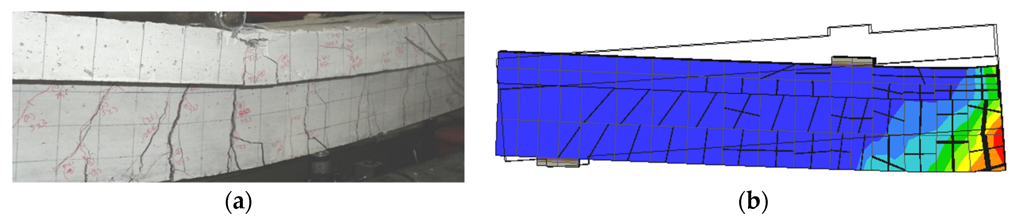
Figure 12 compares the crack patterns observed in the experiment and those predicted by the numerical simulation for the BC beam. In the experiment [48], flexural cracks originated at the bottom surface within the tension zone and propagated upward with increasing load, concentrating in the constant-moment region near mid-span, where bending stresses were highest. As loading progressed, cracks widened and extended vertically, leading to flexural failure. The FE model reproduced a consistent cracking response, capturing the initiation and upward propagation of tensile cracks in regions subjected to high bending moments. However, the simulation shows more transverse cracks than in the experiment, mainly due to the smeared-crack formulation and mesh discretization, which distribute tensile damage rather than localize it into dominant cracks. Despite this, the predicted crack locations, orientations, and propagation trends agree well with the experimental behavior, and the global response and failure mechanism are accurately captured. Therefore, the model remains valid in representing the flexural behavior of the BC beam.
Figure 12.
Crack development in the BC beam: (a) experimental observation [48]; (b) numerical simulation. In the contour plot, red indicates severe damage, while dark blue indicates undamaged or minimally damaged regions. The black lines indicate the predicted crack pattern, whereas the fine grid lines represent the FE mesh.
4.2.2. SWR-Strengthened Beam (BS)
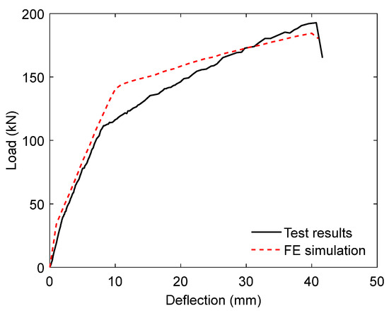
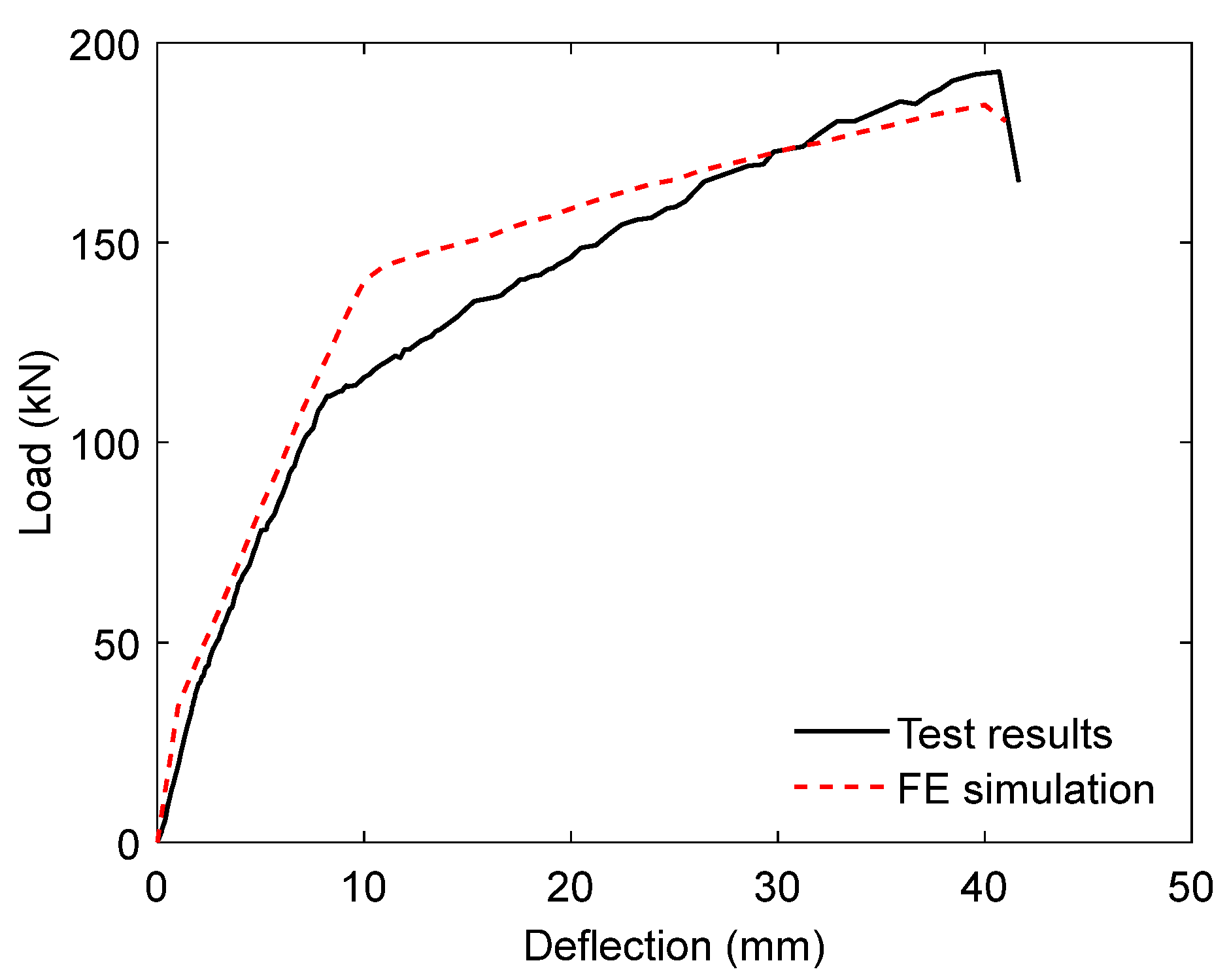
Figure 13 compares the load–deflection curve of the SWR-strengthened beam (BS) obtained from the experimental test and the FE simulation. In general, the numerical model captures the general flexural response of the strengthened beam with good agreement. The simulated curve follows the experimental trend from the initial loading stage to the vicinity of the peak load, indicating that the model can reasonably reproduce the stiffness evolution and progressive nonlinear response of the beam.
Figure 13.
Load–deflection curves for the SWR-strengthened beam (BS) obtained from test results [48] and FE simulation.
However, a noticeable difference appears at low deflection levels, where the simulation predicts a steeper rise and higher load than obtained in the test, suggesting that the numerical model slightly overestimates the initial stiffness. In the intermediate stage, the simulation results remain above the experimental curve, whereas at larger deflections the two responses become closer before reaching the peak region. The numerical model slightly underestimates the maximum load and does not fully capture the sharper post-peak drop observed in the experiment. Nevertheless, the NMSE of 0.006 shows that the deviation between the numerical and experimental responses is small, supporting the reliability of the FE model in representing the global flexural behavior of the SWR-strengthened beam. Further validation was performed by comparing the main flexural response characteristics observed from the experimental test and numerical simulation, as summarized in Table 4.
Table 4.
Comparison of flexural response characteristics of the SWR-strengthened beam (BS) obtained from test results and FE simulation.
The FE model estimated an ultimate load of 184.42 kN, close to the experimental value of 192.80 kN, and a corresponding failure deflection of 41.00 mm, which agrees well with the experimental deflection of 41.64 mm. The predicted stiffness (18.84 kN/mm) and ductility index (4.19) are slightly lower than the experimental values (24.04 kN/mm and 5.19, respectively), indicating a modest underestimation of the deformation capacity by the numerical model. In contrast, the energy absorption capacity predicted in the simulation (5946.08 kN·mm) shows good consistency with the experimental value (5773.23 kN·mm). Overall, the average ratio between the numerical predictions and experimental measurements is 0.91, representing a satisfactory level of agreement. These results confirm that the FE model can adequately predict the flexural response characteristics of the SWR-strengthened beam and is suitable for evaluating the structural performance of strengthened RC members.
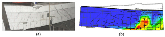
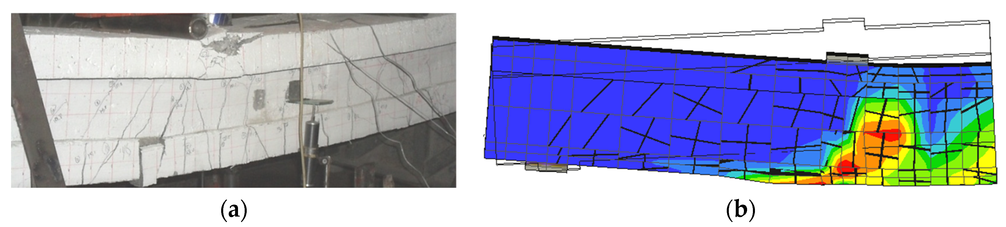
Figure 14 presents the crack patterns and damage distributions in the SWR-strengthened beam (BS) from the numerical simulation and the experimental test. In the experiment [48], multiple inclined cracks formed in the tension region and propagated toward the compression zone with increasing load. The cracks were more widely distributed along the span than in the BC beam, indicating that the SWRs promoted a more uniform redistribution of tensile stresses. Several cracks also extended beneath the loading point, suggesting combined flexural action and local stress concentrations. The numerical simulation produced a comparable damage pattern, with peak strain localization near mid-span extending toward the loading region. However, the simulation shows a denser and more continuous crack pattern than in the experiment, especially near the loading zone, where damage appears more diffuse. This behavior is attributed to the smeared crack formulation and mesh discretization, which distribute tensile damage rather than localize it. Nevertheless, the predicted crack directions and propagation characteristics remain consistent with the experimental observations, while the overall structural response and failure mode are adequately represented.
Figure 14.
Crack development in the SWR-strengthened beam (BS): (a) experimental observation [48]; (b) numerical simulation. In the contour plot, red indicates severe damage, while dark blue indicates undamaged or minimally damaged regions. The black lines indicate the predicted crack pattern, whereas the fine grid lines represent the FE mesh.
4.3. Parametric Investigation
4.3.1. Effect of SWR Diameter
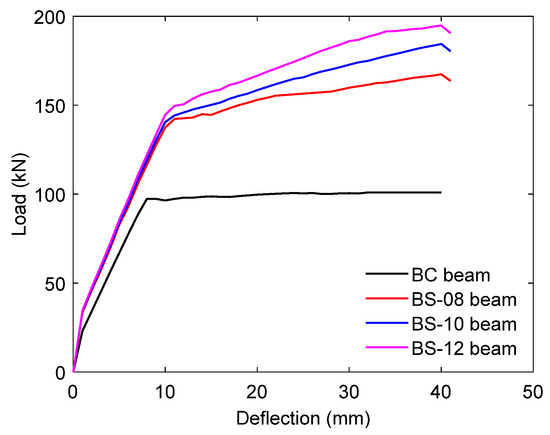
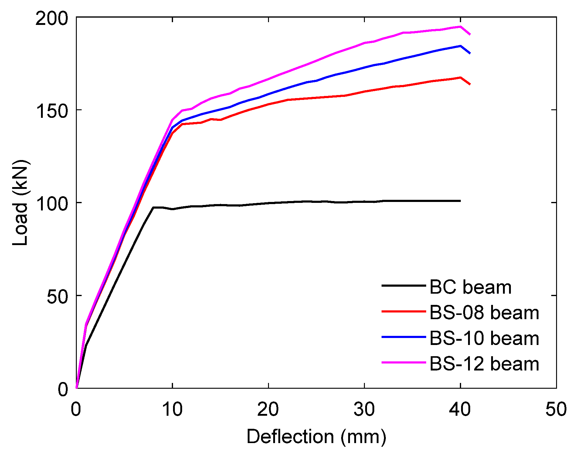
In the first stage of the parametric investigation, the influence of SWR diameter (8, 10, and 12 mm) was evaluated while all other parameters remained constant. The results in Figure 15 and Table 5 show that increasing the diameter significantly enhances flexural performance, with the 12 mm configuration achieving an ultimate load approximately 93.00% higher than that of the 10 mm configuration. In comparison, the 8 mm configuration reaches about 1.66 times the control beam (BC) value. A similar trend is observed in stiffness: the 12 mm configuration increases stiffness to about 1.48 times that of the control beam, whereas the 8 mm configuration shows only a marginal increase relative to the 10 mm configuration.
Figure 15.
Predicted load–deflection curve of the beam with different SWR diameters. All numerical models used a concrete compressive strength of 32.40 MPa and a mortar overlay compressive strength of 49.85 MPa.
Table 5.
Effect of varying SWR diameter on the flexural characteristics of SWR-strengthened beams.
In terms of deformation behavior, the response is less uniform. Reducing the diameter to 8 mm increases the ductility index by about 10.00%, while the 12 mm case remains nearly unchanged. Energy absorption follows the strength trend, with the 12 mm SWR improving capacity by approximately 74.00%, while the 8 mm case reaches about 1.56 times that of BC. These results indicate that increasing diameter primarily enhances strength and stiffness, while its influence on deformation capacity is limited and may lead to reduced ductility.
These trends are governed by the increase in effective reinforcement area, which enhances tensile resistance and improves stress transfer between the SWR and the surrounding concrete. Increasing the SWR diameter leads to earlier engagement of the external reinforcement and reduces tensile demand on the internal steel, thereby delaying reinforcement yielding and increasing load-carrying capacity. However, the nonlinear gain suggests that bond efficiency and strain compatibility constrain the effectiveness at larger diameters, while the increased stiffness limits curvature development and concentrates inelastic deformation within a narrower region.
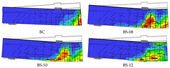
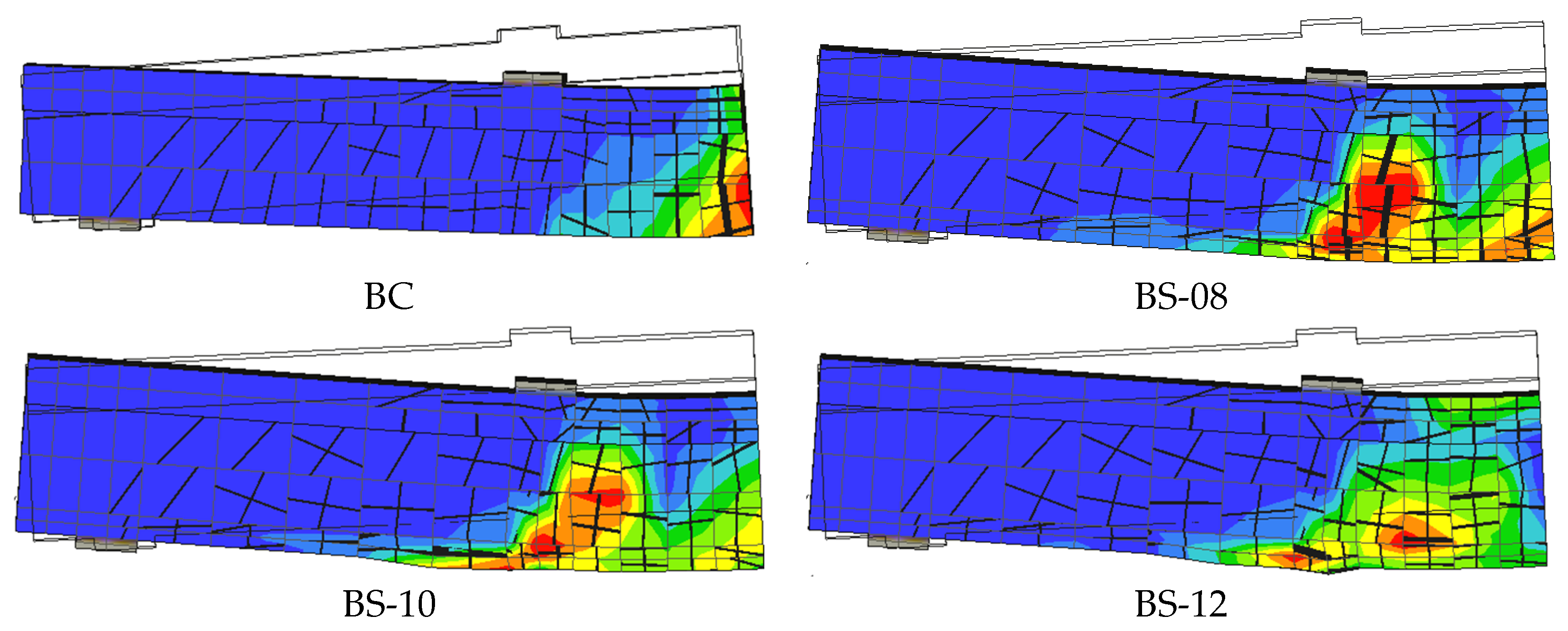
Based on the crack patterns shown in Figure 16, the influence of SWR diameter is clearly reflected in crack distribution and failure characteristics. The 12 mm configuration exhibits fewer but wider inclined cracks with pronounced localization near the loading region, whereas the 8 mm configuration shows a greater number of finer and more widely distributed cracks along the span, with the 10 mm case presenting an intermediate response. This variation confirms that SWR diameter governs not only load capacity but also stiffness, ductility, and energy dissipation in a non-uniform manner. In contrast to earlier studies, which primarily established the general benefits of SWR systems [46,47,48], the present analysis provides parameter-specific insights that support performance-based strengthening design and highlight the importance of diameter optimization.
Figure 16.
Crack patterns of the beam with different SWR diameters. All numerical models used a concrete compressive strength of 32.40 MPa and a mortar overlay compressive strength of 49.85 MPa. In the contour plot, red indicates severe damage, while dark blue indicates undamaged or minimally damaged regions. The black lines indicate the predicted crack pattern, whereas the fine grid lines represent the FE mesh.
4.3.2. Effect of the Compressive Strength of Concrete
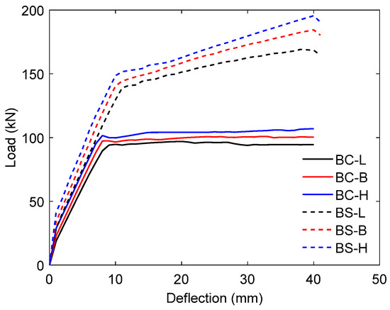
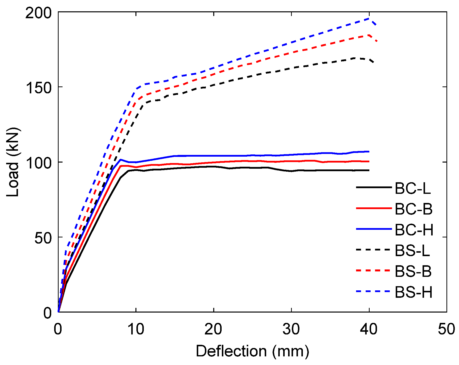
The effect of concrete compressive strength on the flexural response was investigated using three levels of (17.50, 32.40, and 60.00 MPa), representing low-, baseline-, and high-strength conditions. Both control (BC) and strengthened (BS) beams were analyzed while maintaining constant SWR diameter and bonding material strength. The results in Figure 17 and Table 6 show that increasing concrete strength enhances flexural capacity by improving the contribution of the compression zone. Specifically, the ultimate load increased by about 1.13 times in the unstrengthened beam and 1.16 times in the strengthened beam when comparing the lowest and highest strength levels. This improvement is associated with higher compressive resistance and increased modulus of elasticity, which shifts the neutral axis toward the compression region and increases tensile demand on the reinforcement, consistent with previous findings [63,64].
Figure 17.
Predicted load–deflection responses of the beam with various concrete compressive strengths. All numerical models used 10 mm SWRs and a constant compressive strength for the mortar overlay of 49.85 MPa.
Table 6.
Effect of variation in the compressive strength of concrete on the flexural characteristics of SWR-strengthened beams.
The influence of compressive strength is also reflected in stiffness and energy absorption. Increasing the concrete strength from 17.50 to 60.00 MPa results in stiffness increases of approximately 21.00% for the unstrengthened beam and 14.00% for the strengthened beam. Relative to the baseline condition, the high-strength configuration (BS-H) shows a moderate increase of about 6.00%, whereas the low-strength case (BS-L) exhibits a reduction of approximately 8.00%. A similar trend is observed for energy absorption, where BS-H increases by about 5.00%, and BS-L decreases by approximately 6.00%. These results indicate that higher concrete strength enhances elastic stiffness and energy dissipation, although the improvement becomes less pronounced in strengthened members due to the dominant role of external reinforcement.
The underlying mechanism can be explained by the role of concrete in the compression zone and its interaction with the tensile reinforcement system. Higher compressive strength improves the confinement and load-carrying capacity of the compression block, allowing the beam to sustain higher stresses before crushing. However, this also leads to reduced strain capacity in the compression zone, limiting curvature development. In strengthened beams, the presence of SWR further redistributes tensile stresses and constrains deformation, which explains why the relative gains in stiffness and strength do not translate into proportional improvements in ductility. As a result, the structural response is governed by a balance between enhanced compressive resistance and restricted deformation capacity.
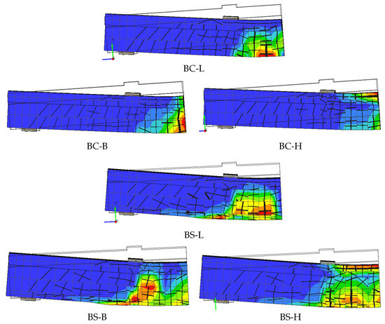
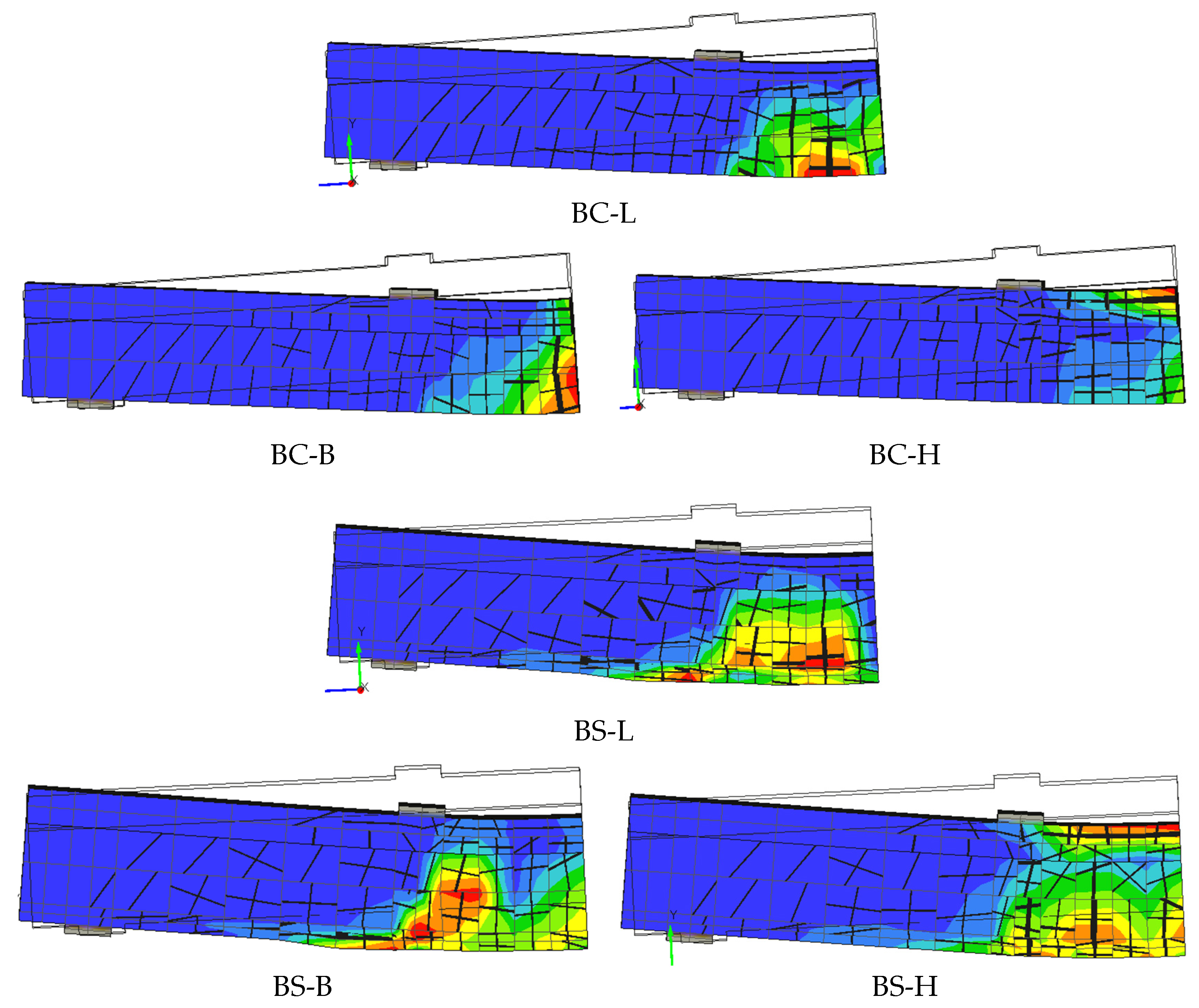
The effect of concrete compressive strength is also evident in both crack development and failure mode, as shown in Figure 18. The low-strength configuration exhibits more extensive and widely distributed cracking, indicating lower stiffness and earlier crack propagation. In contrast, the high-strength configuration shows fewer cracks with more pronounced localization near the loading region, reflecting increased stiffness and delayed crack initiation. The baseline case presents an intermediate response. Despite these differences, all specimens exhibit flexure-dominated failure characterized by crack propagation from the tension zone toward the compression region. These observations confirm that increasing concrete strength modifies crack distribution and stiffness but does not alter the governing failure mechanism, while also reinforcing the trade-off between strength enhancement and deformation capacity in SWR-strengthened systems.
Figure 18.
Crack patterns of the beam with various concrete compressive strengths. All numerical models used 10 mm SWRs and a constant compressive strength for the mortar overlay of 49.85 MPa. In the contour plot, red indicates severe damage, while dark blue indicates undamaged or minimally damaged regions. The black lines indicate the predicted crack pattern, whereas the fine grid lines represent the FE mesh.
4.3.3. Effect of Bonding Material Strength
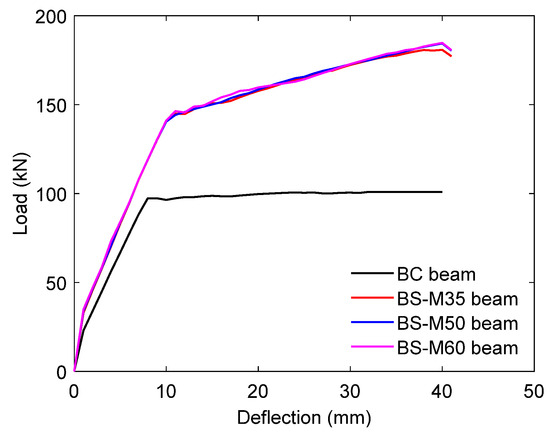
The effect of the strength of the bonding material on the flexural response of SWR-strengthened beams was evaluated using three representative mortar strengths of 35 MPa (BS-M35), 49.85 MPa (BS-M50), and 65 MPa (BS-M65), while maintaining a constant concrete compressive strength of 32.40 MPa and SWR diameter of 10 mm. The load–deflection responses in Figure 19 show that all strengthened beams exhibit significantly higher load-carrying capacity than the control beam (BC), whereas the differences among strengthened configurations remain small. The curves for BS-M35, BS-M50, and BS-M65 follow nearly identical trajectories across the loading stages, indicating that once sufficient bonding is achieved, further increases in bonding strength have a limited influence on the global structural response.
Figure 19.
Predicted load–deflection responses of the beam with varying bonding material strengths. All numerical models used 10 mm SWRs and a constant concrete compressive strength of 32.40 MPa.
A detailed comparison in Table 7 confirms this trend. The ultimate load increases slightly from 180.84 kN (BS-M35) to 184.42 kN (BS-M50) and 185.38 kN (BS-M65), corresponding to incremental gains of approximately 1.98% and 0.52%, respectively. Relative to the control beam (100.93 kN), these represent increases of about 79%, 83%, and 84%. The stiffness values remain nearly unchanged at 18.99, 18.84, and 18.90 kN/mm, corresponding to improvements of approximately 45–46% over the control beam (13.02 kN/mm), with variations of less than 1% among strengthened beams. Energy absorption increases from 5918.77 kN·mm to 5946.08 kN·mm and 5965.17 kN·mm, corresponding to marginal gains of 0.46% and 0.32%, while remaining approximately 65–66% higher than the control beam (3594.11 kN·mm). These results confirm that bonding material strength provides diminishing returns once a sufficient threshold is reached.
Table 7.
Effect of variation in the strength of the bonding material on the flexural characteristics of SWR-strengthened beams.
From a mechanical perspective, the bonding layer primarily governs the efficiency of stress transfer between the SWR and the concrete substrate. At lower strength (35 MPa), the bond is already sufficient to mobilize the tensile capacity of the SWR, enabling effective composite action. Increasing the bonding strength further does not significantly enhance this interaction, as the response becomes controlled by the tensile capacity of the SWR and the internal reinforcement rather than by bond resistance. This explains the minimal variation in stiffness and strength. Additionally, higher bond stiffness slightly restricts interfacial deformation, contributing to a modest reduction in ductility, as reflected by the decrease in ductility index from 4.31 to 4.19 and 4.18. These observations indicate that bonding strength influences the initiation of composite action but has a limited impact on the governing load transfer mechanism once adequate bonding is achieved.
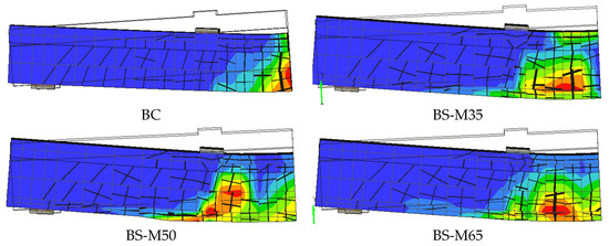
As illustrated in Figure 20, variations in bonding material strength produce only subtle differences in crack distribution and failure characteristics. All strengthened configurations exhibit similar crack patterns, with inclined cracks developing in the tension zone and extending toward the loading region, confirming a flexure-dominated failure mode. The higher-strength bonding cases (BS-M50 and BS-M65) show slightly more localized cracking near the loading region, whereas the lower-strength case (BS-M35) presents marginally more distributed cracking along the span. Nevertheless, these differences remain minor, indicating that the bonding layer primarily ensures continuity of stress transfer rather than controlling crack evolution. In this sense, the structural response is governed by the SWR–concrete interaction rather than the absolute strength of the bonding material, emphasizing that achieving adequate bond is sufficient for effective strengthening without requiring excessive material strength.
Figure 20.
Crack patterns of a beam with varying bonding material strengths. All numerical models used 10 mm SWRs and a constant concrete compressive strength of 32.40 MPa. In the contour plot, red indicates severe damage, while dark blue indicates undamaged or minimally damaged regions. The black lines indicate the predicted crack pattern, whereas the fine grid lines represent the FE mesh.
5. Structural Insights and Design Implications
This study provides detailed insights into the behavior of RC T-beams strengthened with bonded SWR systems. The results indicated that the strengthening mechanism is governed by the interaction between the SWR, bonding layer, and internal reinforcement, which modifies stress distribution in the tension zone. Among the parameters, SWR diameter is the most influential. An intermediate diameter of 10 mm is recommended as a balanced choice, providing significant strength and stiffness enhancement without excessive stiffness. Smaller diameters favor ductility, while larger ones show diminishing efficiency. In contrast, concrete and bonding material strengths have limited influence once adequate levels are reached. A concrete strength of ≥30 MPa and a bonding strength of 35–50 MPa are sufficient to ensure effective stress transfer, representing a practical design range.
From a design perspective, a balanced configuration is more important than maximizing individual parameters. Increasing SWR diameter enhances load capacity but also increases stiffness, potentially reducing ductility. Similarly, higher concrete and bonding strengths improve stiffness and strength but have a limited influence on deformation capacity. These trends are consistent with design guidance for FRP-based strengthening systems [65], which emphasizes effective bond and stress transfer. However, unlike FRP systems, no specific provisions exist for SWR strengthening, particularly regarding reinforcement size and the strength–ductility trade-off. This highlights the need for refined, system-specific design recommendations.
6. Conclusions
The present involved a systematic parametric evaluation of the flexural behavior of RC T-beams strengthened with bonded SWR systems. A three-dimensional FE model, calibrated against experimental observations [48], was employed to reproduce the structural response under monotonic loading and to investigate the influence of the main design variables. The evaluation addressed the roles of SWR diameter, concrete compressive strength, and bonding material strength in controlling the overall behavior of the strengthened beams. From the results obtained, the following conclusions may be stated:
- The incorporation of bonded SWRs significantly enhances the flexural capacity of RC T-beams, as evidenced by the increase in crack initiation, yielding, and ultimate load levels. Despite these improvements, the governing mechanism of failure is flexural for both the unstrengthened and the strengthened specimens.
- The FE model developed here demonstrates good predictive capability within the scope of the simplifying assumptions, including perfect bond conditions, smeared-crack modeling, and geometric symmetry. Although these simplifications ensure stable and efficient simulations, they may reduce the direct simulation of localized cracking and interface behavior.
- Increasing the SWR diameter had the most significant impact on flexural performance. The ultimate load was increased by a factor of up to 1.93 compared to that of the control beam, with corresponding improvements in stiffness (by a factor of up to 1.48) and energy dissipation (by a factor of 1.74). However, these gains were accompanied by a reduction in ductility, indicating that the size of the SWR primarily affected the strength and stiffness rather than the deformation capacity.
- The effect of the concrete compressive strength was moderate: increasing the value from 17.50 to 60 MPa resulted in improvements in the load capacity of up to 16% and stiffness gains of up to 21%, while the energy absorption increased only slightly. The effect on ductility was limited, particularly for strengthened beams.
- Variations in the strength of the bonding material had a minimal influence once adequate bond conditions had been achieved. Increasing the bond strength led to only marginal improvements in ultimate load and negligible changes in stiffness, indicating diminishing returns beyond a threshold level.
- Across all parameters, improvements in strength and stiffness were consistently associated with reduced ductility in the strengthened beams. This highlights an inherent trade-off between deformation capability and load-carrying capacity that must be considered in performance-based design.
- Crack patterns varied with strengthening parameters. Larger SWR diameters and higher concrete strength promoted crack localization, while smaller diameters and lower strength led to distributed cracking. Bonding strength had minimal influence once an adequate bond was achieved, with all cases showing flexure-dominated failure.
- Although these findings confirm the effectiveness of SWR strengthening under monotonic loading, the conclusions are limited to the parameter ranges investigated here. Further studies incorporating cyclic loading and bond–slip behavior are recommended to support a broader range of practical applications.
Author Contributions
Conceptualization, A.T.A., Y.H., H.-T.H. and G.H.S.; methodology, A.T.A., Y.H., F.-P.H. and G.H.S.; software, Y.H., G.H.S. and N.A.B.; validation, P.S.N., L.N. and N.A.B.; formal analysis, A.T.A., Y.H., G.H.S. and N.A.B.; investigation, Y.H., G.H.S., P.S.N. and N.A.B.; resources, A.T.A. and H.-T.H.; data curation, F.-P.H., P.S.N. and L.N.; writing—original draft preparation, A.T.A., Y.H., G.H.S., L.N. and N.A.B.; writing—review and editing, A.T.A., Y.H., F.-P.H., P.S.N. and L.N.; visualization, Y.H., L.N. and N.A.B.; supervision, A.T.A., H.-T.H., G.H.S. and P.S.N.; project administration, A.T.A. and H.-T.H.; funding acquisition, A.T.A. and H.-T.H. All authors have read and agreed to the published version of the manuscript.
Funding
This research was funded by the Institute for Research and Community Service (LPPM), Universitas Atma Jaya Yogyakarta (UAJY), Indonesia, under Assignment Letter No. 33/LPPM-Pen/In, awarded to the first author (A.T.A.). Partial support was also provided by the National Science and Technology Council (NSTC), Taiwan, under Grant No. 114-2625-M-006-014, awarded to the third author (H.-T.H.).
Data Availability Statement
The key findings and contributions of this work are fully documented in this article. Further clarification may be obtained from the corresponding authors upon request.
Acknowledgments
During the preparation of this manuscript, ChatGPT (OpenAI, San Francisco, CA, USA: GPT-5.2) was employed to assist with language polishing, structural refinement, and enhancement of clarity and coherence in selected sections. It was additionally used to support rephrasing and formatting in accordance with the journal’s stylistic requirements. All outputs were critically reviewed and revised by the authors, who assume full responsibility for the accuracy, integrity, and originality of the final manuscript.
Conflicts of Interest
The authors declare no conflicts of interest.
Abbreviations
The following abbreviations are used in this manuscript:
| RC | Reinforced concrete |
| SWR | Steel wire rope |
| FRP | Fiber-reinforced polymer |
| CFRP | Carbon fiber-reinforced polymer |
| NSM | Near-surface mounted |
| HSC | High-strength concrete |
| FE | Finite element |
| LVDTs | Linear variable differential transformers |
| ATENA | Advanced Tool for Engineering Nonlinear Analysis |
| NMSE | Normalized Mean Squared Error |
References
- Peiris, A.; Harik, I. Design and construction of CFRP rod panel retrofit for impacted RC bridge girders. J. Compos. Sci. 2018, 2, 40. [Google Scholar] [CrossRef] [Scilit]
- Akbarpour, A.; Volz, J.; Vemuganti, S. An experimental study incorporating carbon fiber composite bars and wraps for concrete performance and failure insight. J. Compos. Sci. 2024, 8, 174. [Google Scholar] [CrossRef] [Scilit]
- Elgholmy, L.; Salim, H.; Elsisi, A.; Salama, A.; Shaaban, H.; Elbelbisi, A. Prestressed CFRP plates and tendon strengthening of steel–concrete composite Beams. J. Compos. Sci. 2024, 8, 301. [Google Scholar] [CrossRef] [Scilit]
- Haryanto, Y.; Hsiao, F.-P.; Hu, H.-T.; Nugroho, L.; Lin, C.-C.; Weng, P.-W.; Cheng, Y.-Y.; Hidayat, B.A. Strengthening strategy for RC T-beams in negative-moment region using steel-reinforced polymer cement mortar. Buildings 2025, 15, 4011. [Google Scholar] [CrossRef] [Scilit]
- Haryanto, Y.; Hu, H.-T.; Hsiao, F.-P.; Nugroho, L.; Wu, M.-H.; Weng, P.-W.; Lin, C.-C. Numerical assessment of RC T-beams strengthened in the negative moment region with UHPC overlays. Comput. Concr. 2026, 37, 565–594. [Google Scholar]
- Hsiao, F.-P.; Lin, C.-C.; Weng, P.-W.; Haryanto, Y.; Llano, S.P.; Hu, H.-T.; Nugroho, L.; Calad, A.S.; Hidayat, B.A. Seismic per-formance of a hybrid structural steel–reinforced concrete coupled wall building: Preliminary response estimates from an NCREE–QuakeCoRE joint study. Buildings 2026, 16, 246. [Google Scholar] [CrossRef] [Scilit]
- Hsiao, F.-P.; Lin, C.-C.; Weng, P.-W.; Haryanto, Y.; Nugroho, L.; Huang, C.-H. Alternative strengthening strategies to improve the seismic resilience of RC frame structures. J. Build. Eng. 2026, 119, 115078. [Google Scholar] [CrossRef] [Scilit]
- Jiang, X.; Cao, D.Q.; Qiang, X.H.; Xu, C.L. Study on fatigue performance of steel bridge welded joints considering initial defects. J. Constr. Steel Res. 2024, 212, 108309. [Google Scholar] [CrossRef] [Scilit]
- Yang, B.; Hu, X.; Li, A.; Zhao, T.; Sun, Y.Q.; Fu, H. Degradation mechanism of cast-in-situ concrete under long-term sulfate saline soil attack. Constr. Build. Mater. 2025, 478, 141401. [Google Scholar] [CrossRef] [Scilit]
- Li, J.; Lan, L.; Zhang, Y.; Pan, B.; Shi, W.; Gu, Z.; Zhang, Y.; Yan, Y.; Wang, J.; Zhou, J.; et al. Advancements in basalt fi-ber-reinforced composites: A critical review. Coatings 2025, 15, 1441. [Google Scholar] [CrossRef] [Scilit]
- Lei, D.; Liu, L.; Ma, X.; Luo, M.; Gong, Y. Experimental and numerical investigation of fatigue performance in reinforced concrete beams strengthened with engineered cementitious composite layers and steel plates. Coatings 2025, 15, 54. [Google Scholar] [CrossRef] [Scilit]
- Zheng, H.; Hu, Y.; Gong, Z.; He, H. Study on the Flexural capacity of reinforced concrete beams strengthened with UHPC thin layers considering interface slip. Buildings 2026, 16, 562. [Google Scholar] [CrossRef] [Scilit]
- Tworzewski, P.; Bacharz, K. Flexural Strengthening of reinforced concrete beams using near-surface mounted (NSM) carbon fiber-reinforced polymer (CFRP) strips with additional anchorage. Materials 2025, 18, 2579. [Google Scholar] [CrossRef] [Scilit]
- Ye, X.; Li, Z.; Shen, H.; Zheng, H. Flexural behavior of reinforced concrete beams strengthened with novel BFRP plates. Buildings 2026, 16, 1031. [Google Scholar] [CrossRef] [Scilit]
- Huangz, W.; Yen, C.-H.; Hung, C.-C. Flexural and shear strengthening of lightly reinforced concrete beams using CFRP bars and UHPC overlays. Case Stud. Constr. Mater. 2025, 22, e04666. [Google Scholar] [CrossRef] [Scilit]
- Nugroho, L.; Haryanto, Y.; Hsiao, F.-P.; Hu, H.-T.; Weng, P.-W.; Lin, C.-C.; Kristiawan, S.A.; Sangadji, S. Effectiveness of UHPC reinforced with steel rebars for flexural strengthening of RC T-beams in an idealized negative moment region. Structures 2025, 10, 109728. [Google Scholar] [CrossRef] [Scilit]
- Sudibyo, G.H.; Wariyatno, N.G.; Mulyono, B.; Haryanto, Y.; Hu, H.-T.; Hsiao, F.-P.; Nugroho, L.; Hidayat, B.A.; Sari, S.T. Computational Insights into the Use of Polymer Cement Mortar for Negative Moment Strengthening in RC T-Beams. Coatings 2026, 16, 303. [Google Scholar] [CrossRef] [Scilit]
- Kodur, V.; Rayala, T.; Kim, H.S. Rational approach for evaluating fire resistance of prestressed concrete beams strengthened with fiber-reinforced polymers. Polymers 2025, 17, 2773. [Google Scholar] [CrossRef] [Scilit]
- Han, A.L.; Hu, H.-T.; Gan, B.S.; Hsiao, F.-P.; Haryanto, Y. Carbon fiber-reinforced polymer rod embedment depth influence on concrete strengthening. Arab. J. Sci. Eng. 2022, 47, 12685–12695. [Google Scholar] [CrossRef] [Scilit]
- Haryanto, Y.; Wariyatno, N.G.; Hsiao, F.-P.; Hu, H.-T.; Han, A.L.; Nugroho, L.; Hartono, H. RC T-beams with flexural strengthening in the negative moment region under different configurations of NSM CFRP rods. Eng. Fail. Anal. 2025, 173, 109458. [Google Scholar] [CrossRef] [Scilit]
- Haryanto, Y.; Hsiao, F.-P.; Hu, H.-T.; Han, A.L.; Chua, A.W.; Salim, F.; Nugroho, L. Structural behavior of negative moment region NSM-CFRP strengthened RC T-beams with various embedment depth under monotonic and cyclic loading. Compos. Struct. 2022, 301, 116214. [Google Scholar] [CrossRef] [Scilit]
- Haryanto, Y.; Hermanto, N.I.S.; Hsiao, F.-P.; Hu, H.-T.; Han, A.L.; Nugroho, L.; Salim, F. Predicting the behavior of RC T-beams strengthened with NSM-CFRP rods in the negative moment region: A finite element approach for low cyclic loading. E3S Web Conf. 2023, 464, 06001. [Google Scholar] [CrossRef] [Scilit]
- Nugroho, L.; Haryanto, Y.; Hu, H.-T.; Han, A.L.; Hsiao, F.-P.; Lin, C.-C.; Weng, P.-W.; Widiastuti, E.P. NSM-CFRP rods with varied embedment depths for strengthening RC T-beams in the negative moment region: Investigation on high cyclic response. Compos. Struct. 2024, 331, 117891. [Google Scholar] [CrossRef] [Scilit]
- Abbaszadeh, A.; Chaallal, O. Resilience of medium-to-high-rise ductile coupled shear walls located in Canadian seismic zones and strengthened with externally bonded fiber-reinforced polymer composite: Nonlinear time history assessment. J. Compos. Sci. 2023, 7, 317. [Google Scholar] [CrossRef] [Scilit]
- Nugroho, L.; Haryanto, Y.; Hu, H.-T.; Hsiao, F.-P.; Pamudji, G.; Setiajdi, B.H.; Hsu, C.-N.; Weng, P.-W.; Lin, C.-C. Prestressed concrete T-beams strengthened with near-surface mounted carbon-fiber-reinforced polymer rods under monotonic loading: A finite element analysis. Eng 2025, 6, 36. [Google Scholar] [CrossRef] [Scilit]
- Haryanto, Y.; Hu, H.-T.; Atmajayanti, A.T.; Hsiao, F.-P.; Nugroho, L.; Wariyatno, N.G. Simulation-based study on the per-formance of NSM-CFRP strengthening in prestressed concrete T-beams under seismic loading. Materials 2025, 18, 4386. [Google Scholar] [CrossRef] [Scilit]
- Sudibyo, G.H.; Nugroho, L.; Haryanto, Y.; Hu, H.-T.; Hsiao, F.-P.; Nugroho, P.S.; Wariyatno, N.G.; Hidayat, B.A.; Kuncoro, D.T. Shear–flexure integrated strengthening of RC beams with near-surface mounted carbon fiber-reinforced polymer (CFRP) ropes and geopolymer overlays. C 2026, 12, 21. [Google Scholar] [CrossRef] [Scilit]
- Emara, M.; Salem, M.A.; Mohamed, H.A.; Shehab, H.A.; El-Zohairy, A. Shear strengthening of reinforced concrete beams using engineered cementitious composites and carbon fiber-reinforced polymer sheets. Fibers 2023, 11, 98. [Google Scholar] [CrossRef] [Scilit]
- Mussa, M.H.; Mutalib, A.A.; Hao, H. Experimental and numerical study of carbon fibre-reinforced polymer-strengthened re-inforced concrete beams under static and impact loads. Fibers 2024, 12, 63. [Google Scholar] [CrossRef] [Scilit]
- Alasmari, H.A.; Sharaky, I.A.; Elamary, A.S.; El-Zohairy, A. Rehabilitation and strengthening of damaged reinforced concrete beams using carbon fiber-reinforced polymer laminates and high-strength concrete integrating recycled tire steel fiber. Fibers 2025, 13, 10. [Google Scholar] [CrossRef] [Scilit]
- Khalil, A.; Elkafrawy, M.; Hawileh, R.; AlHamaydeh, M.; Abuzaid, W. Numerical Investigation of flexural behavior of reinforced concrete (RC) T-Beams strengthened with pre-stressed iron-based (FeMnSiCrNi) shape memory alloy bars. J. Compos. Sci. 2023, 7, 258. [Google Scholar] [CrossRef] [Scilit]
- Ibrahim Hassanin Mohamed, A.; Shaaban, H. Synergistic Hybrid strengthening of RC beams: Integrating externally bonded CFRP with elastomeric polyurea coatings. J. Compos. Sci. 2026, 10, 178. [Google Scholar] [CrossRef] [Scilit]
- Chang, X.-D.; Huang, H.-B.; Peng, Y.-X.; Li, S.-X. Friction, wear and residual strength properties of steel wire rope with different corrosion types. Wear 2020, 458–459, 203425. [Google Scholar] [CrossRef] [Scilit]
- Zhang, K.M.; Shen, X.; Liu, J.; Teng, F.; Zhang, G.; Wang, J. Flexural strengthening of reinforced concrete T-beams using a composite of prestressed steel wire ropes embedded in polyurethane cement (PSWR-PUC): Theoretical analysis. Structures 2022, 44, 1278–1287. [Google Scholar] [CrossRef] [Scilit]
- Li, X.; Zhou, X.; Xiao, L.; Liu, Z.; Zhou, Z. Quasi-static experimental study on reinforcing aerated concrete block walls through steel wire rope-olymer mortar surface layer cross-strip method. Structures 2023, 57, 105266. [Google Scholar] [CrossRef] [Scilit]
- Zhang, M.; Yang, X.; Ding, Y.; Xu, P.; Sun, B.; Zhang, X.; Zhang, X. Flexural behavior of RC beams with NSM prestressed helical rib steel wire. KSCE J. Civ. Eng. 2023, 27, 3887–3900. [Google Scholar] [CrossRef] [Scilit]
- Guo, R.; Zhang, H.; Chen, K.; Song, Y.; Li, H.; Ding, L.; Liu, Y. Seismic performance analysis of concrete columns reinforced with prestressed wire ropes embedded in polyurethane cement composites. Buildings 2024, 14, 993. [Google Scholar] [CrossRef] [Scilit]
- Wei, Y.; Li, K.; Fan, J.; Li, Y.; Li, S. Seismic response of RC short columns strengthened by high-strength stainless steel wire rope meshes reinforced ECC jacket. Constr. Build. Mater. 2024, 439, 137419. [Google Scholar] [CrossRef] [Scilit]
- Wei, Y.; Li, K.; Ge, H.; Fan, J.; Zhu, J. Effect of the repeated loading on bond properties between steel wire rope and engineered cementitious composites. Constr. Build. Mater. 2025, 494, 143545. [Google Scholar] [CrossRef] [Scilit]
- Wu, G.; Wu, Z.S.; Jiang, J.B.; Tian, Y.; Zhang, M. Experimental study of RC beams strengthened with distributed prestressed high-strength steel wire rope. Mag. Concr. Res. 2010, 62, 253–265. [Google Scholar] [CrossRef] [Scilit]
- Wu, G.; Wu, Z.S.; Wei, Y.; Jiang, J.B.; Cui, Y. Flexural strengthening of RC beams using distributed prestressed high strength steel wire rope: Theoretical analysis. Struct. Infrastruct. Eng. 2014, 10, 160–174. [Google Scholar] [CrossRef] [Scilit]
- Wei, Y.; Wu, Y.F. Compression behavior of concrete columns confined by high strength steel wire. Constr. Build. Mater. 2014, 54, 443–453. [Google Scholar] [CrossRef] [Scilit]
- JGJ/T 325-2014; Technical Specification for Strengthening Concrete Structures with Prestressed High Strength Steel Wire Ropes. General Administration of Quality Supervision, Inspection and Quarantine of the People’s Republic of China: Beijing, China, 2014. (In Chinese)
- Li, X.; Wu, G.; Popal, M.S.; Jiang, J. Experimental and numerical study of hollow core slabs strengthened with mounted steel bars and prestressed steel wire ropes. Constr. Build. Mater. 2018, 188, 456–469. [Google Scholar] [CrossRef] [Scilit]
- Miao, W.; Guo, Z.-X.; Ye, Y.; Basha, S.H.; Liu, X.-J. Flexural behavior of stone slabs strengthened with prestressed NSM steel wire ropes. Eng. Struct. 2020, 222, 111046. [Google Scholar] [CrossRef] [Scilit]
- Haryanto, Y.; Sudibyo, G.H.; Nugroho, L.; Hu, H.-T.; Han, A.L.; Hsiao, F.-P.; Widyaningrum, A.; Susetyo, Y. Flexural perfor-mance of the negative moment region in bonded steel-wire-rope-strengthened reinforced concrete T-beams at different pre-stressing levels. Adv. Struct. Eng. 2024, 27, 2338–2358. [Google Scholar] [CrossRef] [Scilit]
- Haryanto, Y.; Hsiao, F.-P.; Nugroho, L.; Hu, H.-T.; Sudibyo, G.H.; Wariyatno, N.G.; Hidayat, B.A.; Pamudji, G. Enhancing the negative moment flexural capacity of RC T-beams with bonded steel wire ropes—A parametric study. Eng. Fail. Anal. 2025, 180, 109883. [Google Scholar] [CrossRef] [Scilit]
- Atmajayanti, A.T.; Haryanto, Y.; Hsiao, F.-P.; Hu, H.-T.; Nugroho, L. Effective flexural strengthening of reinforced concrete T-beams using bonded fiber-core steel wire ropes. Fibers 2025, 13, 53. [Google Scholar] [CrossRef] [Scilit]
- Naser, M.Z.; Hawileh, R.A.; Abdalla, J. Modeling strategies of finite element simulation of reinforced concrete beams strengthened with FRP: A review. J. Compos. Sci. 2021, 5, 19. [Google Scholar] [CrossRef] [Scilit]
- Abbasi, A.; Benzeguir, Z.E.A.; Chaallal, O.; El-Saikaly, G. FE modelling and simulation of the size effect of RC T-beams strengthened in shear with externally bonded FRP fabrics. J. Compos. Sci. 2022, 6, 116. [Google Scholar] [CrossRef] [Scilit]
- Ayyobi, P.; Barros, J.A.O.; Dias, S.J.E. Numerical Assessment of the Effect of CFRP Anchorages on the Flexural and Shear Strengthening Performance of RC Beams. J. Compos. Sci. 2024, 8, 348. [Google Scholar] [CrossRef] [Scilit]
- ACI 318-19; Building Code Requirements for Structural Concrete and Commentary. American Concrete Institute: Farmington Hills, MI, USA, 2019.
- Cervenka, V.; Cervenka, J.; Janda, Z.; Pryl, D. ATENA Program Documentation Part 8: User’s Manual for ATENA-GID Interface; Cervenka Consulting: Prague, Czech Republic, 2021. [Google Scholar]
- Alwash, D.; Kalfat, R.; Al-Mahaidi, R. Numerical modelling of RC beams strengthened in shear using NSM FRP and cement based adhesives. Structures 2023, 57, 105217. [Google Scholar] [CrossRef] [Scilit]
- Palomo, I.R.I.; Frappa, G.; de Almeida, L.C.; Trautwein, L.M.; Pauletta, M. Analytical and numerical models to determine the strength of RC exterior beam–column joints retrofitted with UHPFRC. Eng. Struct. 2024, 312, 118244. [Google Scholar] [CrossRef] [Scilit]
- Sudibyo, G.H.; Haryanto, Y.; Hsiao, F.-P.; Hu, H.-T.; Nugroho, L.; Pamudji, G.; Widyaningrum, A.; Nugroho, P.S. Three-dimensional finite element analysis of externally strengthened RC beams in flexure with SWR. Lect. Notes Civ. Eng. 2025, 625, 267–275. [Google Scholar]
- Comité Euro-International du Béton. CEB-FIP Model Code 1990: Design Code; Thomas Telford Publishing: London, UK, 1993. [Google Scholar]
- Cervenka, V. Constitutive model for cracked reinforced concrete. J. Proc. 1985, 82, 877–882. [Google Scholar]
- Kupfer, H.; Hilsdorf, H.K.; Rüsch, H. Behavior of concrete under biaxial stresses. J. Proc. 1969, 66, 656–666. [Google Scholar] [CrossRef] [Scilit]
- ASTM C39/C39M-21; Standard Test Method for Compressive Strength of Cylindrical Concrete Specimens. ASTM International: West Conshohocken, PA, USA, 2021.
- ASTM A370-18; Standard Test Methods and Definitions for Mechanical Testing of Steel Products. ASTM International: West Conshohocken, PA, USA, 2018.
- Zheng, Y.-Z.; Wang, W.-W.; Mosalam, K.M.; Fang, Q.; Chen, L.; Zhu, Z.-F. Experimental investigation and numerical analysis of RC beams shear strengthened with FRP/ECC composite layer. Compos. Struct. 2020, 246, 112436. [Google Scholar] [CrossRef] [Scilit]
- Alabdulhady, M.Y.; Ojaimi, M.F.; Chkheiwer, A.H. The efficiency of CFRP strengthening and repair system on the flexural behavior of RC beams constructed with different concrete compressive strength. Results Eng. 2022, 16, 100763. [Google Scholar] [CrossRef] [Scilit]
- Ashour, S.A. Effect of compressive strength and tensile reinforcement ratio on flexural behavior of high-strength concrete beams. Eng. Struct. 2000, 22, 413–423. [Google Scholar] [CrossRef] [Scilit]
- ACI 440.2R-08; Guide for the Design and Construction of Externally Bonded FRP Systems for Strengthening Concrete Structures. American Concrete Institute: Farmington Hills, MI, USA, 2008.

Disclaimer/Publisher’s Note: The statements, opinions and data contained in all publications are solely those of the individual author(s) and contributor(s) and not of MDPI and/or the editor(s). MDPI and/or the editor(s) disclaim responsibility for any injury to people or property resulting from any ideas, methods, instructions or products referred to in the content. |
© 2026 by the authors. Licensee MDPI, Basel, Switzerland. This article is an open access article distributed under the terms and conditions of the Creative Commons Attribution (CC BY) license.