


Abstract
In this study, the structure and mechanical properties of composites fabricated by polyetherimide film and powder lamination of carbon fabrics, as well as their impregnation with a polyetherimide/N-methylpyrrolidone solution at different contents, were compared. At compression sintering pressure of 10 MPa, the most uniform structure with the minimum number of discontinuities was formed by film lamination at the maximum carbon fabric content of 70 wt.%. For powder lamination, some discontinuities were found in the composites, which may be caused by the low melt flow index of the polyetherimide powder. The composites fabricated by impregnation with the dissolved PEI possessed low mechanical properties, so the compression sintering pressure was reduced to 6 MPa. After that, an improved composite was characterized by both uniform structure and high mechanical properties (even above those at film lamination), confirming the effectiveness of this fabrication method.
1. Introduction
The history of polymer-based composites involves continuous innovation and co-development of both resins and reinforcing materials. Those based on thermosetting resins dominate in the fabrication of components for aircraft, advanced sports equipment, and other high-tech applications due to their stiffness, great specific strengths, and proven production routes [1,2,3,4]. However, their brittleness and damageability, as well as the difficulty of recycling and reusing, limit wider implementations, particularly in civil aviation and automotive industries [3,4,5].
In this concern, the design of carbon fiber (CF) reinforced polymer composites (CFRPCs) based on high-performance thermoplastic resins (HPTRs) is regarded as a major paradigm shift in this field of R&D. In contrast to thermosetting grades, thermoplastic resins are characterized by both development potentials and application prospects due to unlimited shelf life of ingredients and superior strengths, weldability and remeltability [4,6,7,8]. Among the HPTRs, polyetherimide (PEI) is the most extensively studied binder. As an amorphous polymer, PEI possesses the glass transition temperature of 217 °C (allowing it to meet stringent service requirements [9]), high strength, flame retardancy (the UL94 V-0 rating), and hydrolytic stability [5]. This combination of functional characteristics facilitates its replacement of conventional materials in civil aircraft interiors and supporting structures, as well as electronics and electrical components [9,10].
The main challenge in the design of high-performance CFRPCs (in particular PEI-based ones) is the high melt viscosity of thermoplastic binders. This feature distinguishes them from low-viscosity thermosetting resin precursors, which easily wet and impregnate reinforcing CF bundles [11]. Complete and uniform distribution of PEI (and its analogs) is difficult [6,12,13], while insufficient wetting increases the porosity of composites and disrupts the uniformity of placement and tension of CFs, as well as damages them in some cases. Furthermore, adhesion of CFs to matrixes/binders is impaired, forming stress raisers and deteriorating the mechanical properties [14,15].
The above impregnation issue has prompted attempts to fabricate composites by various methods [11,12,13,16]. The basic idea is to combine polymer resins with CFs in different physical states to achieve the greatest impregnation effect during the final compression sintering stage. Currently, three key approaches are applied for the PEI/CF systems (such as tapes or biaxial fabrics), differing in terms of the physical principle and the process implementation:
(i) Lamination of CF fabrics (unidirectional fiber tapes) and polymer films is widely implemented in various industries, and different components for the fabrication of composites are commercially available. Thermoplastic films, in particular PEI, with thicknesses from 50 to 250 µm, are alternately laid out with CF fabrics (the stack method). Upon compression sintering, the film layers are melted and distributed in the transverse direction (in the plane) under applied pressures, filling macroscopic gaps between CF bundles. This method is simple, provides precise control over binder contents, and is one of the most widely used approaches [17,18,19]. Nevertheless, the structures of such composites greatly depend on the process durations, applied pressures (rather high in most cases), and temperatures. In three-dimensional complex-shaped products, polymer binders could be distributed unevenly within reinforcing layers of the CF fabrics.
(ii) Lamination of CF fabrics with powders is aimed at facilitating the penetration of molten polymer resins into reinforcing layers. According to the fluidization principle, either in a suspension state, PEI powders with particles of tens of microns in size are sintered onto the surfaces of CF bundles or embedded into them (the calendering method can also be used for this purpose) [20,21]. Subsequently, during the compression sintering process, powder particles are locally melted, partially penetrating inside the CF bundles. So, the reinforcing components are distributed more efficiently and uniformly [22]. However, both sizes and distributions of powder particles have a significant impact on the structures of such composites and, accordingly, their mechanical properties.
(iii) Dissolution of polymers followed by impregnation of reinforcing CF fabrics represents a completely different and promising technical approach (e.g., for PEI using N-methylpyrrolidone (NMP) as a solvent) [23,24]. Its main advantage is the ability to reduce the high viscosity of PEI, facilitating its distribution among CF bundles even at room temperature due to the capillary effect. Respectively, better pre-wetting is achieved as when using thermosetting resins [25,26]. This method enables the formation of uniform polymer “coatings” on the CF surfaces prior to compression sintering, thereby transforming the primary objective of the composite fabrication process from the labor-intensive “melt wetting” to the relatively simple “solvent evaporation” and “sintering of CF fabric layers impregnated with polymer resins.” Such an approach minimizes porosity but improves the structures at the interfaces between phases and layers. When fabricating three-dimensional complex-shaped products, which are difficult to obtain using both the above-described methods, it is possible to achieve uniform impregnation by injection or spraying of dissolved polymers. Thus, new opportunities are opening up for the fabrication of in-demand products from high-performance CFRPCs [27].
Although all three methods have been validated generally, trade-offs between the cost efficiency and the functional performance of industrial-scale products remain critical. Particularly for the PEI/CF fabric composites, some knowledge gaps should be fulfilled for fact-based selection and optimization of the production route parameters. The unsolved issues include the lack of information on the influence of polymer resins on the structures of composites (impregnation degree, porosity, interface morphology, etc.) and their mechanical properties (flexural and tensile strengths, as examples).
By analyzing the experimental results reported in [28,29], the authors defined the aim of this study as a comparison of the structure and the mechanical properties of composites fabricated by both PEI film and powder lamination of commercially available reinforcing CF fabrics, as well as their impregnation with a PEI/NMP solution at different contents. The null hypothesis was the possibility of attaining high functional characteristics by the use of the polymer dilution method.
2. Materials and Methods
2.1. Materials
Investigated composites were fabricated from (i) the TECAPEI PEI film, (ii) the Solver PEI ROOH powder (Solver, Jiande, China) with particle sizes of ~20 μm, and (iii) the same PEI powder dissolved in NMP (C5H9NO) as a matrix (binder) that was reinforced with the ASM C285S twill-weave CF fabric (UMATEX, Moscow, Russia).
2.2. Fabrication of the Composites
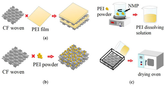
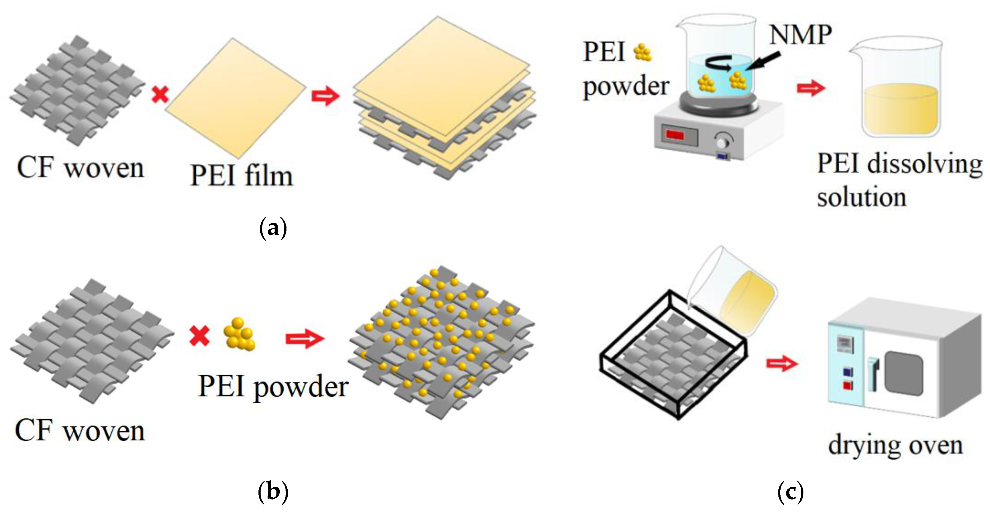
Film lamination: The compression sintering process of the 70 × 65 mm mechanically cut and layer-by-layer stacked fragments of the CF fabric and the PEI film is schematically shown in Figure 1a.
Figure 1.
Schematic illustrations of the production route for the studied composites: (a) film lamination; (b) powder lamination; (c) impregnation with PEI dissolved in NMP.
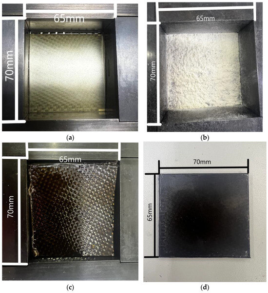
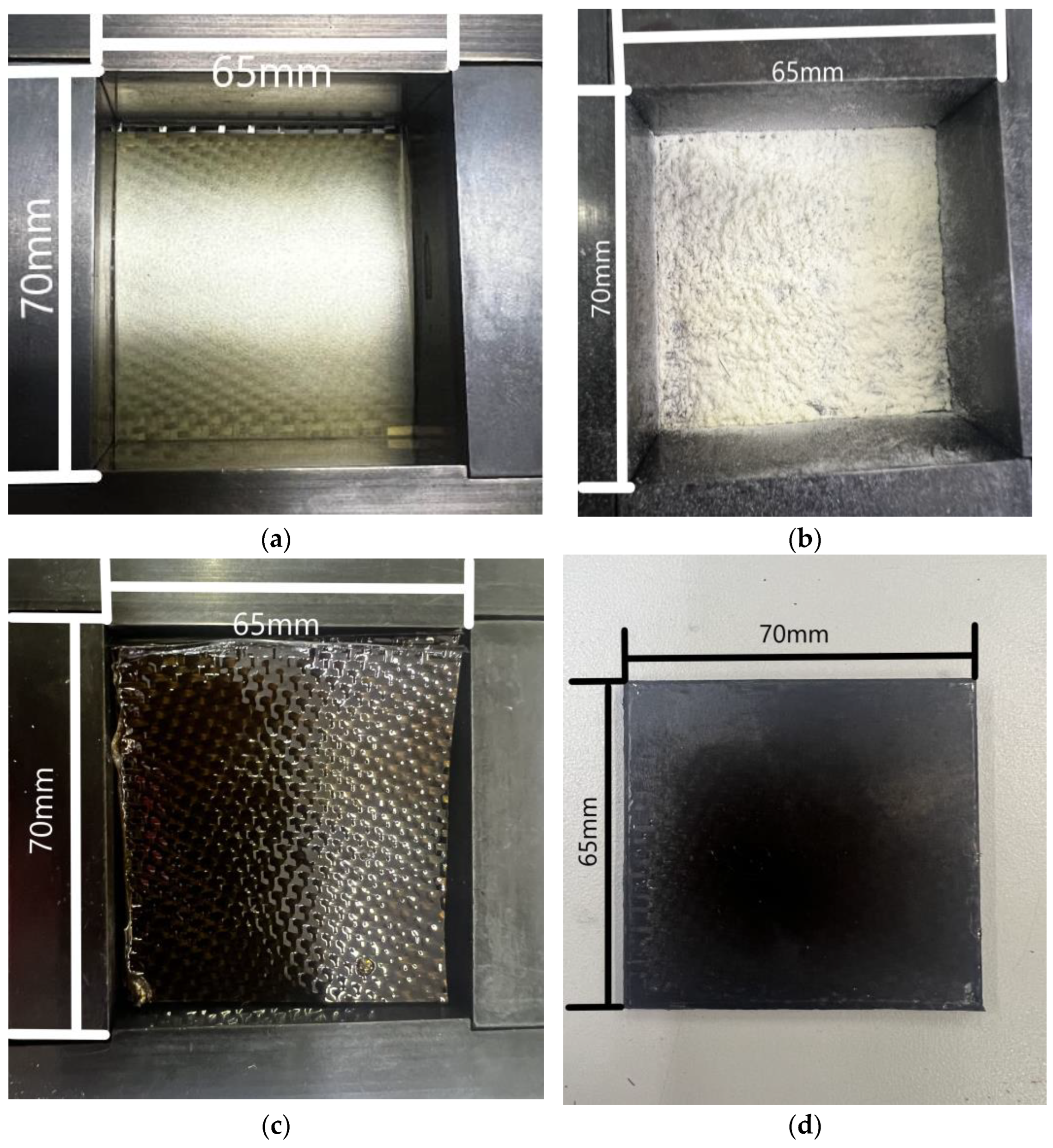
To achieve the required thickness of the composites (~2 mm), six layers of the CF fabric, as well as 14, 21, and 35 layers of the PEI film (folded in 2, 3, and 5 pieces), were successively stacked. These packs were covered with a single layer of the PEI film on both the top and bottom. A general view of such a blank inside a mold before compression sintering is presented in Figure 2a.
Figure 2.
The general views of the layer-by-layer stacked components prepared for compression sintering: (a) CF-fabric and PEI film; (b) CF-fabric and PEI powder; (c) CF-fabric impregnated with the dissolved PEI; (d) a fabricated composite.
Powder lamination. In these cases, 5.8, 11.2, and 15.6 g of the PEI powder were evenly distributed between six layers of the CF fabric (Figure 1b) for varying the binder contents. The PEI powder was divided into seven equal portions and, in addition to the space between the CF-fabric fragments, was placed in the bottom and top of the stacked packs to form the outer layers (Figure 1b and Figure 2b).
Impregnation with the dissolved polymer. Initially, the PEI powder was dissolved in NMP by heating up to 145 °C with continuous stirring at a ratio of 1 g powder to 10 mL solvent. The obtained solution was poured onto six CF fabric fragments sequentially arranged in stacks with a thickness of 2.3 mm (Figure 2c).
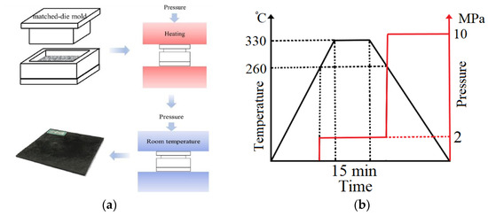
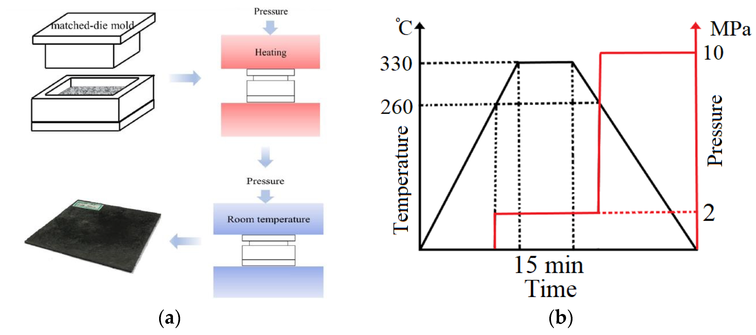
Finally, the composites 70 × 65 × 2 mm3 in size (Figure 2d) were fabricated by compression sintering in a “GT-7014-A 122” heat press (GOTECH Testing Machines Inc., Taichung City, China, Taiwan) according to the applied mode shown in Figure 3. Table 1 presents their designations and brief descriptions.
Figure 3.
(a,b) The compression sintering mode upon the fabrication of the composites.
Table 1.
The designations and brief descriptions of the studied composites.
2.3. Mechanical Tests
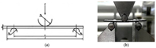
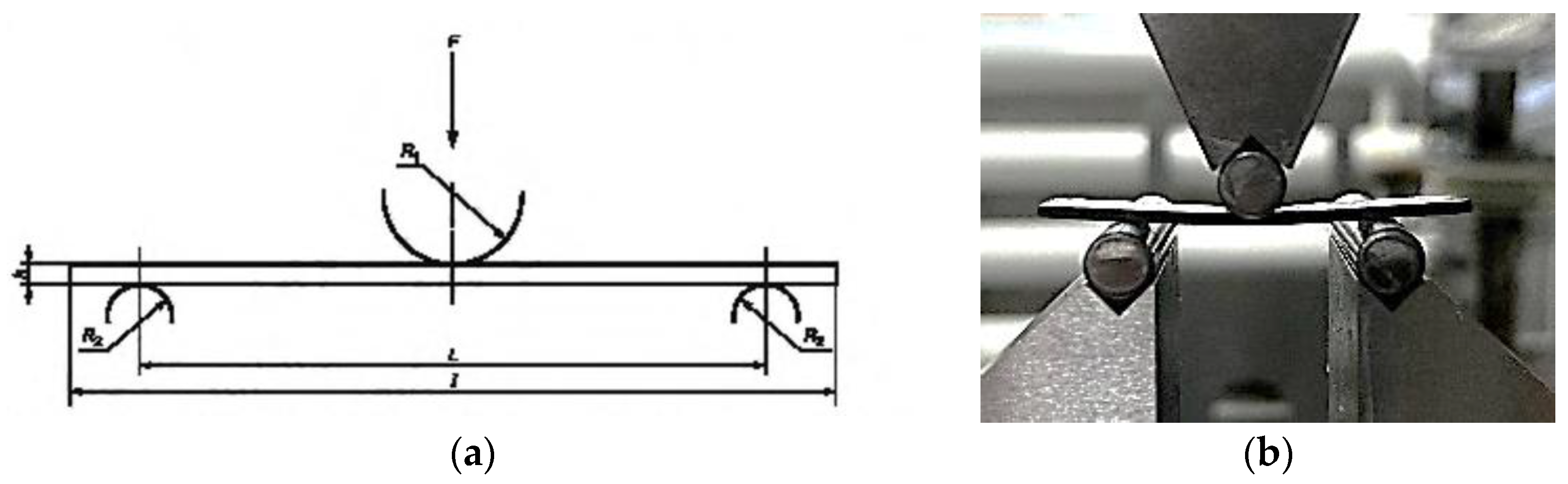
For three-point bending tests, specimens 65(l) × 10(b) × 1.5 − 2.0(h) mm in size were cut using a CNC vertical milling machine (“NPO Pure Logic” LLC, MoscowRussia). The tests were performed with an “Instron 5582” electromechanical testing machine (Instron, Norwood, MA USA) according to ASTM D790-10 (Figure 4) with a span (L) between supports of 20 × h mm and a cross-head speed of 1 mm/min.
Figure 4.
A scheme of the three-point bending tests (a) and a photograph of the testing rig (b).
The bending strength, MPa, was calculated using the formula:
where L is the span (distance between the supports), mm;
b is the specimen width, mm;
h is the specimen thickness, mm.
The stain on the outer specimen surface is determined according to:
where, is the bending deflection, mm.
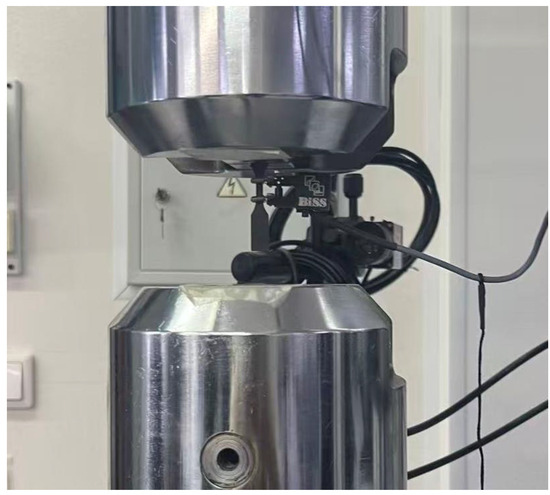
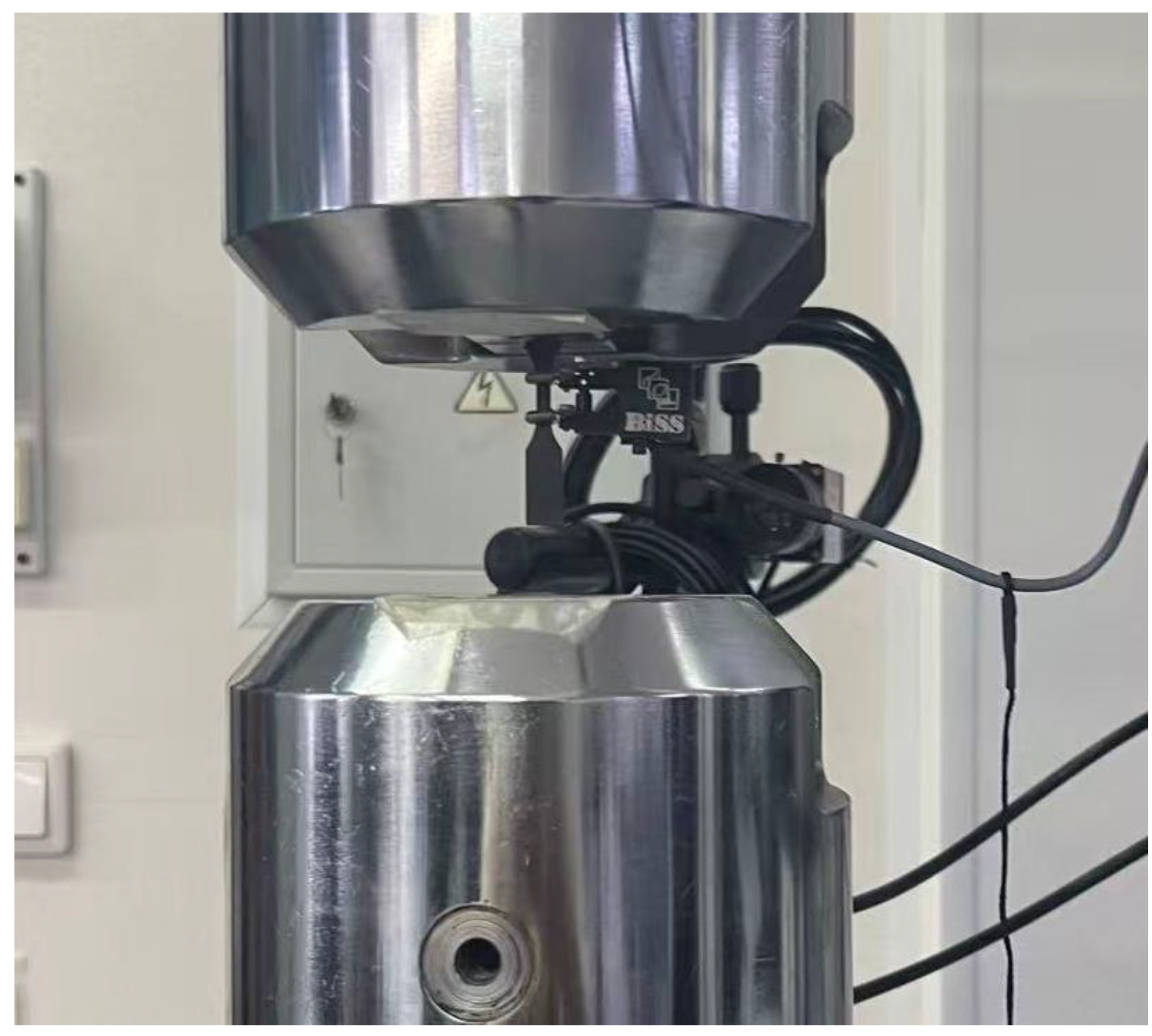
Tensile tests were carried out using a “NANO BISS ITW” electromechanical testing machine (BISS, Bangalore, India) in accordance with ASTM D3039 [30] (Figure 5) at a cross-head speed of 0.5 mm/min.
Figure 5.
A general view of a sample mounted in the grips of the NANO BISS ITW servohydraulic testing machine.
2.4. Structural Characterizations
The structures of the composites were analyzed over their cross-sections with a “Neophot 2” optical microscope (OM; Carl Zeiss, Jena, Germany) equipped with a ‘Canon 700D’ digital single-lens reflex camera (Japan). In addition, scanning electron microscopy (SEM) was employed, for which copper films were deposited on the specimen surfaces with a “Quorum Technologies EMITECH K450X” setup (Quorum Technologies, Laughton, UK). To investigate the structures in the subsurface layers of the specimens, an “Apreo 2 S” SEM (Thermo Fisher Scientific, Waltham, MA, USA) was used at an accelerated voltage of 25 kV and a beam current of 0.80 nA.
3. Results
3.1. Flexural Strengths
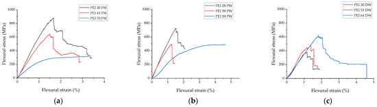
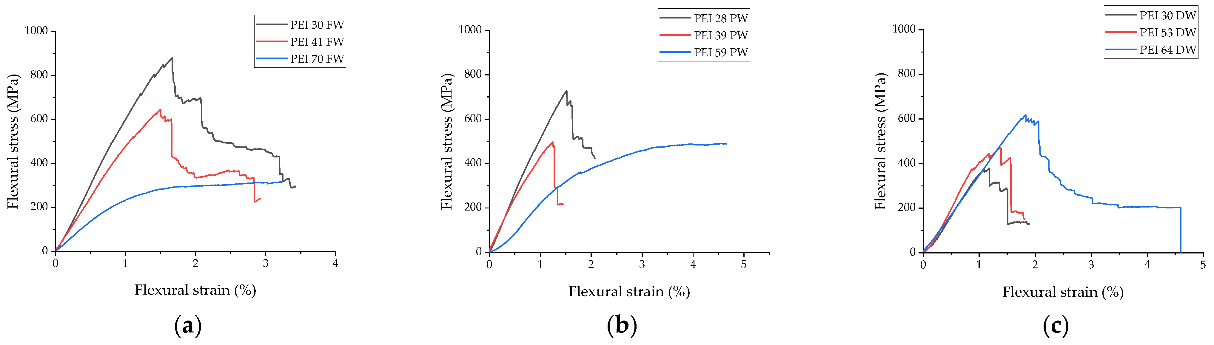
Figure 6 shows three-point bending diagrams for the studied composites. The greatest strength was achieved by the film lamination method (Figure 6a).
Figure 6.
The three-point bending diagrams for the composites fabricated by film lamination (a), powder lamination (b), and impregnation with the dissolved polymer (c).
As expected, the greater the CF fabric content, the higher the stress at failure. It should be noted that at the maximum PEI contents, failure did not occur until the end of the tests (ε = 3.3%). Some lower flexural strength properties were characteristic of the powder lamination method (Figure 6b), with the same trend in the flexural strain (as a function of the CF fabric content). The minimum flexural stress was observed for impregnation with the dissolved polymer: at a CF fabric content of 70 wt.%, the flexural strength barely exceeded 600 MPa, while failure occurred at a strain of 4.5%. So, the latter method demonstrated the lowest efficiency under the applied composite fabrication conditions.
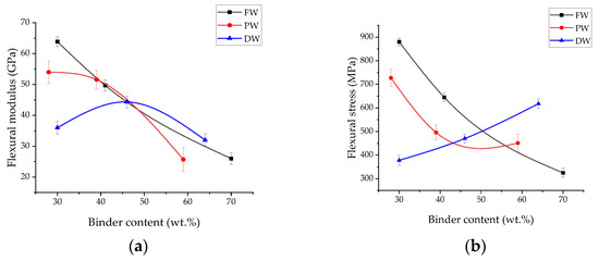
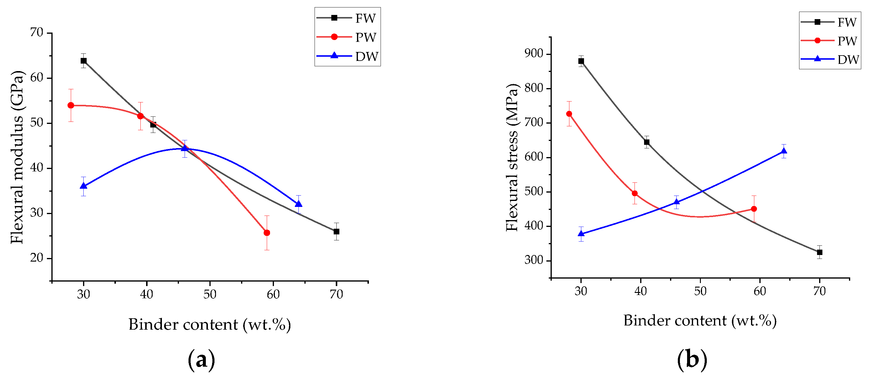
Figure 7 shows the dependence of the bending modulus and the flexural strength on the binder content in the studied composites (fabricated under the identical compression sintering conditions). Considering the film lamination curve as a reference, the flexural moduli decreased significantly at high CF fabric contents, typical for the composites fabricated by impregnation with the dissolved polymer (most likely due to the specific pattern of the formed structures). On the other hand, the flexural moduli for all three fabrication methods were virtually identical (~30 GPa) at high binder contents of 60–70 wt.% (Figure 7a).
Figure 7.
The dependences of the flexural modulus (a) and the flexural strength (b) on the binder content in the PEI/CF composites.
The pattern of changes in the flexural strengths differed. While the film lamination method validated the maximum efficiency with its values of >850 MPa at great CF fabric contents, values of >600 MPa were typical for the composites fabricated by impregnation with the dissolved polymer in other cases. For this fabrication method, it increased almost linearly as a function of the binder content (Figure 7b). These results are discussed in more detail below by analyzing OM images of the fractured specimens (Figure 8).
Figure 8.
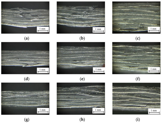
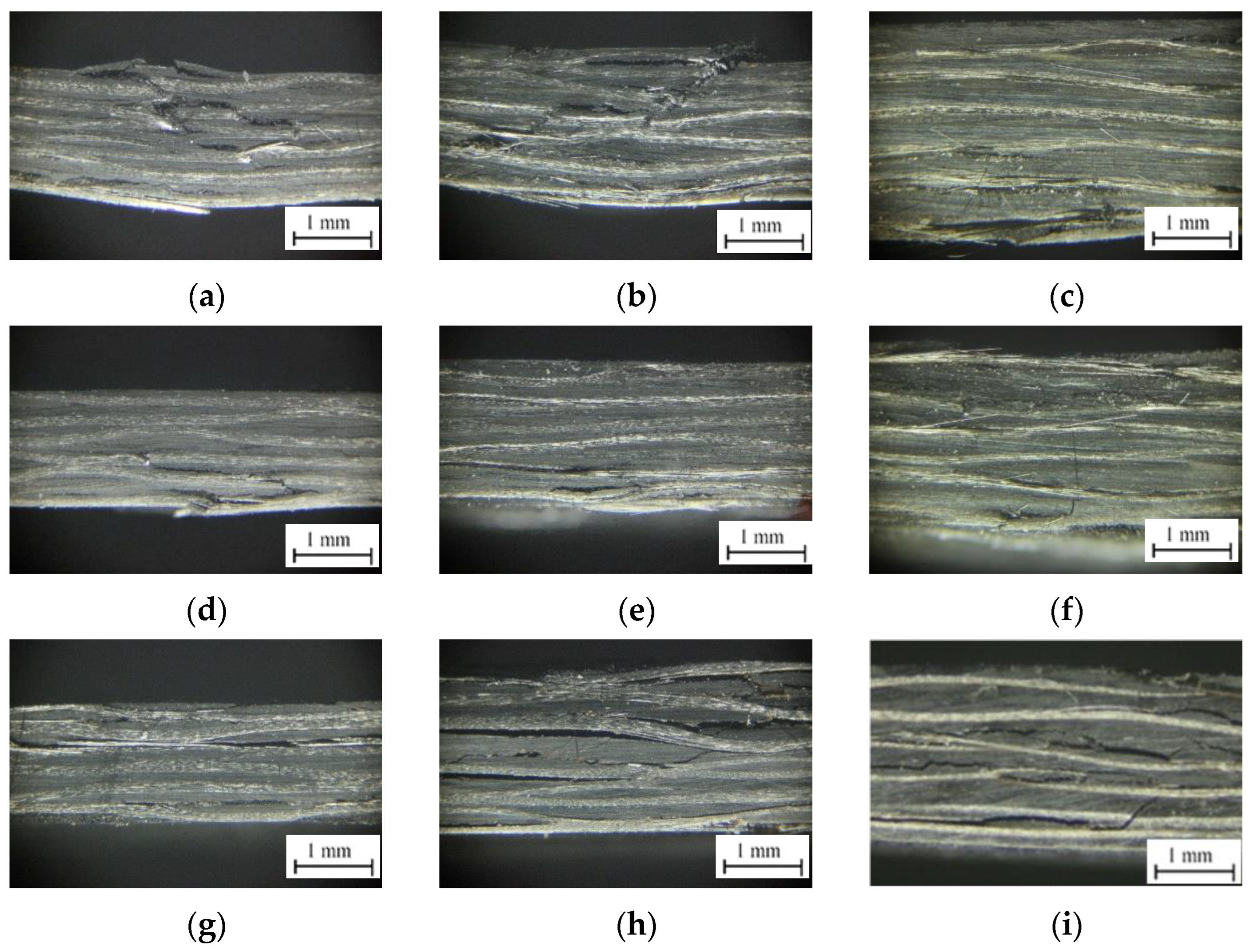
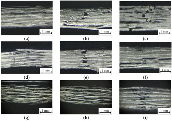
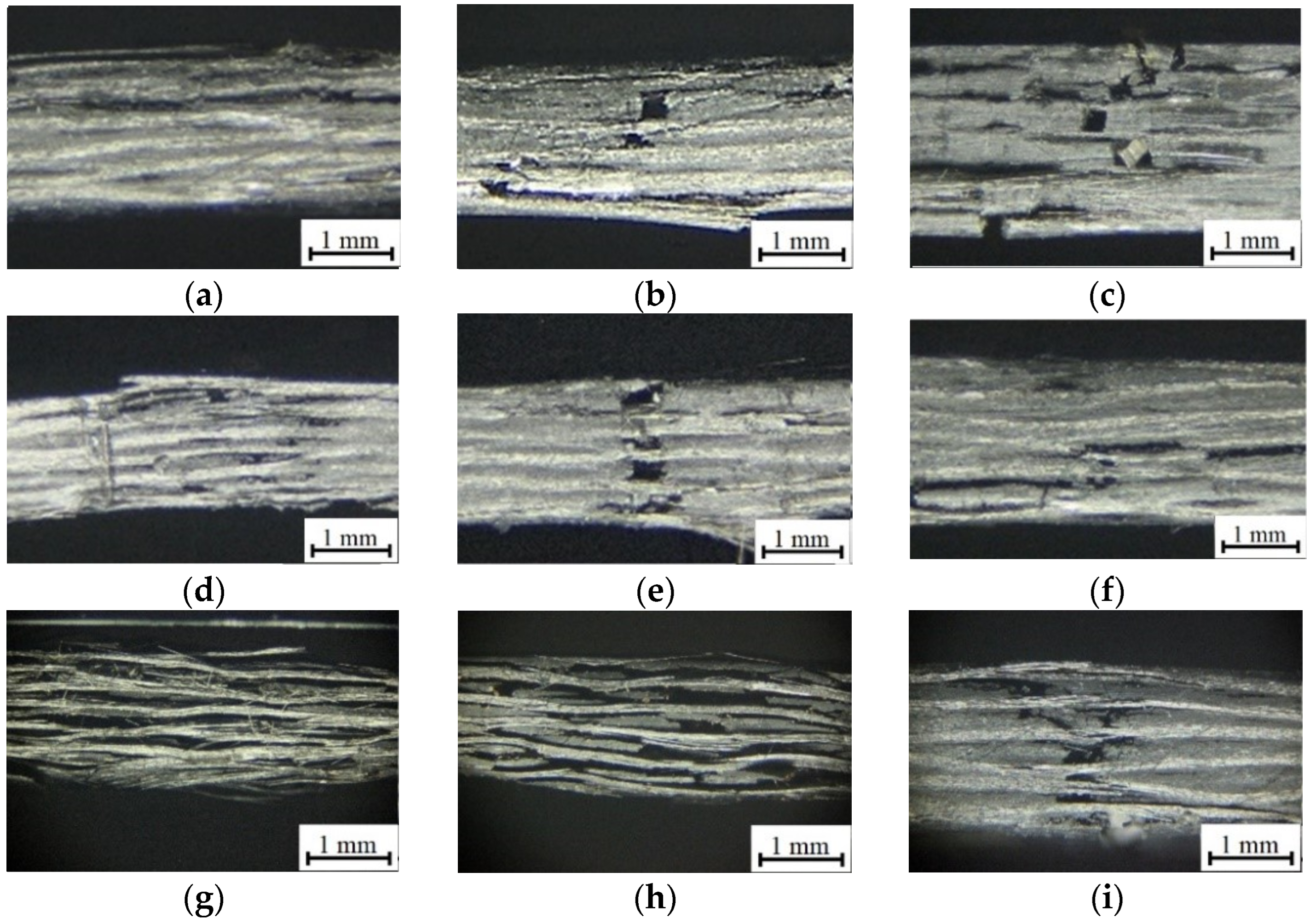
The OM images of the cross-sections of the specimens after the three-point bending tests: (a)—PEI30FW; (b)—PEI41FW; (c)—PEI70FW; (d)—PEI28PW; (e)—PEI39PW; (f)—PEI59PW; (g)—PEI30DW; (h)—PEI53DW; (i)—PEI64DW.
According to Figure 8a–c, the film lamination method allowed the formation of layered structures with components of fairly uniform thicknesses. During the three-point bending tests, some individual short cracks initiated, but no main ones propagated through the entire cross-sections at the interfaces between layers. At the same time, even specimens with high CF fabric contents did not fail after reaching their ultimate flexural strengths (Figure 6a). This fact indicated their great fracture toughness and adhesion between adjacent layers (although no interlaminar shear strength tests were performed).
In the composites fabricated by powder lamination, both the number and extent of cracks at the interfaces between layers were higher (Figure 8d–f). On the one hand, this fact reflected both non-uniformity and the presence of discontinuities at the interfaces. On the other hand, it could characterize low adhesion between adjacent layers, which reduced both flexural modulus and flexural strength (Figure 7). It should be noted that no specimen fractured due to the propagation of a main transverse crack was observed in Figure 8 (typical for the three-point bending tests) since the interlayer boundaries acted as effective barriers to such a failure.
The greatest number and extent of cracks at the interfaces between layers were found in the composites fabricated by impregnation with the dissolved PEI (Figure 8g–i). At the high CF fabric content of 70 wt.%, this observation corresponded to the lowest both flexural modulus and flexural strength among the tested specimens (Figure 7). However, all these indicators were the opposite at low CF fabric contents. The longitudinal cracks shown in Figure 8i did not exert a decisive influence on the fracture process, and the specimen did not fail for a long time after reaching the ultimate flexural strength (Figure 6c).
3.2. Tensile Strengths
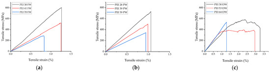
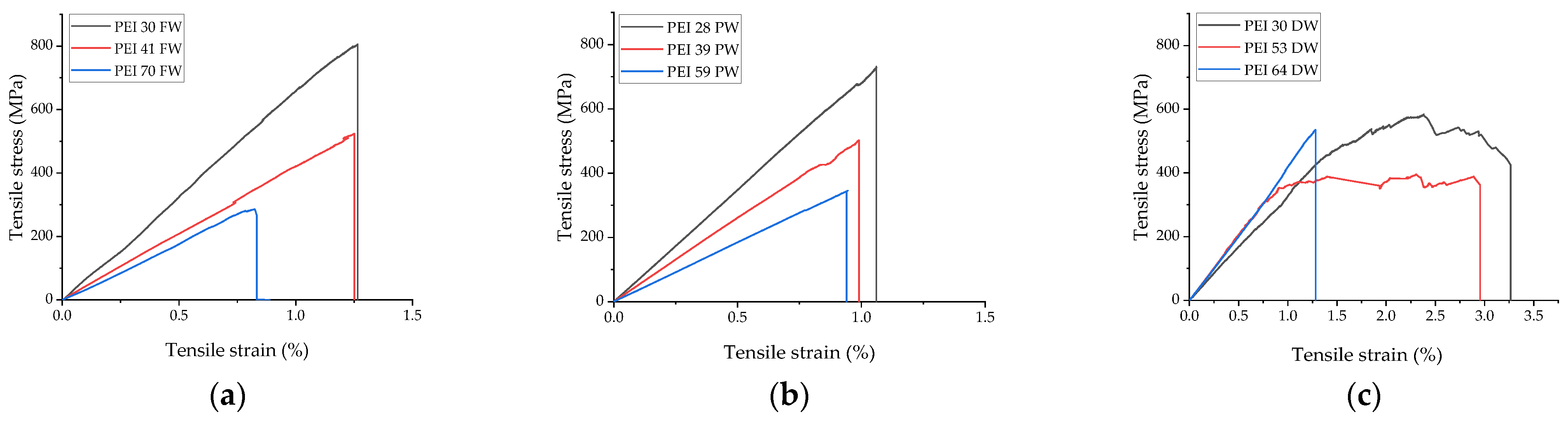
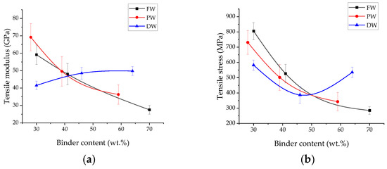
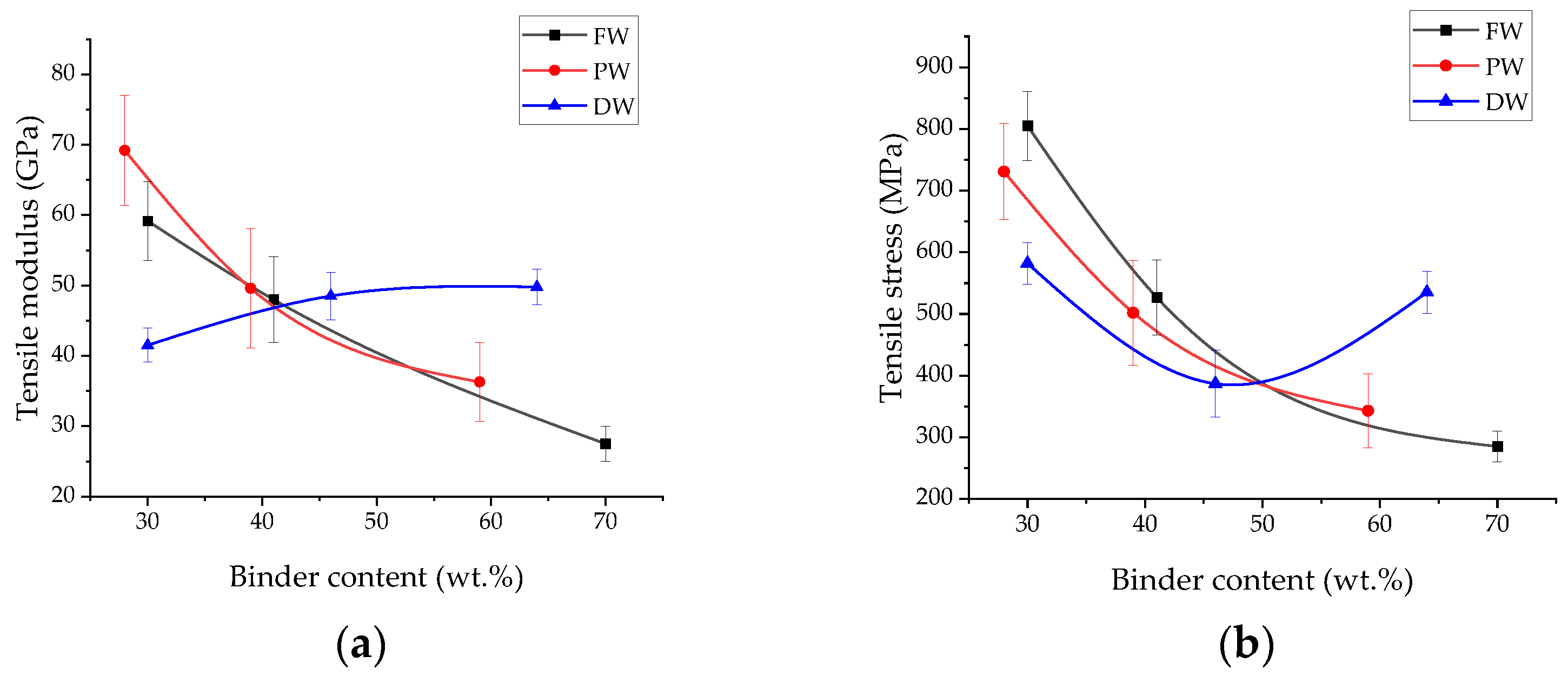
Stress-strain diagrams recorded during the tensile tests of the studied composites are shown in Figure 9. Overall, the pattern of their changes was similar to that obtained in the three-point bending tests; however, some variations should be highlighted. In particular, the composites fabricated by both film and powder lamination exhibited brittle failure (Figure 9a,b) at all component ratios, and their ultimate tensile strengths improved with increasing the CF fabric contents. The tensile modulus of the one fabricated by impregnation with the dissolved polymer at the maximum CF fabric content of 64 wt.% was significantly lower than that inherent for the other two methods (Figure 10a). On the other hand, the composite with the minimum CF fabric content of 30 wt.% was characterized by significantly higher tensile modulus and ultimate tensile strength (Figure 10a,b). These results are explained below when analyzing OM images of the samples after the tensile tests (Figure 11).
Figure 9.
The tensile stress-strain diagrams for the composites fabricated by film lamination (a), powder lamination (b), and impregnation with the dissolved polymer (c).
Figure 10.
The dependences of the tensile modulus (a) and the ultimate tensile strength (b) vs. the binder content in the PEI/CF composites.
Figure 11.
The OM images of the cross-sections of the samples after the tensile tests: (a)—PEI30FW; (b)—PEI41FW; (c)—PEI70FW; (d)—PEI28PW; (e)—PEI39PW; (f)—PEI59PW; (g)—PEI30DW; (h)—PEI53DW; (i)—PEI64DW.
Since some layers of the specimens were subjected to tensile stresses while others were to compressive ones during the three-point bending tests, non-uniform strains of adjacent layers were one of the causes of interlayer cracking. Upon the tensile tests, all layers were stretched equally. Consequently, transverse cracks in individual layers played a decisive role (Figure 11b,c,e,f,h,i). These patterns corresponded to the composites with both minimum and medium CF fabric contents, while cracks were present at the interfaces between layers at their maximum levels (Figure 11a,d,g). The latter result was in good agreement with the ultimate tensile strength of the composite with a CF fabric content of ~30 wt.% (Figure 10b). Nevertheless, the low tensile modulus of the one fabricated by impregnation with the dissolved PEI (~40 GPa according to Figure 10a) testifies to the presence of discontinuities. To investigate this aspect in more detail, the OM examinations were carried out at a higher magnification (Figure 12).
Figure 12.
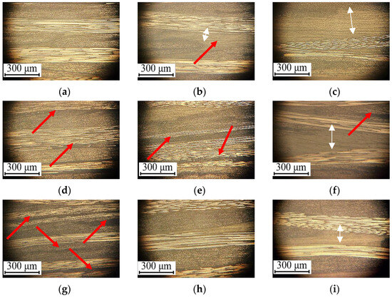
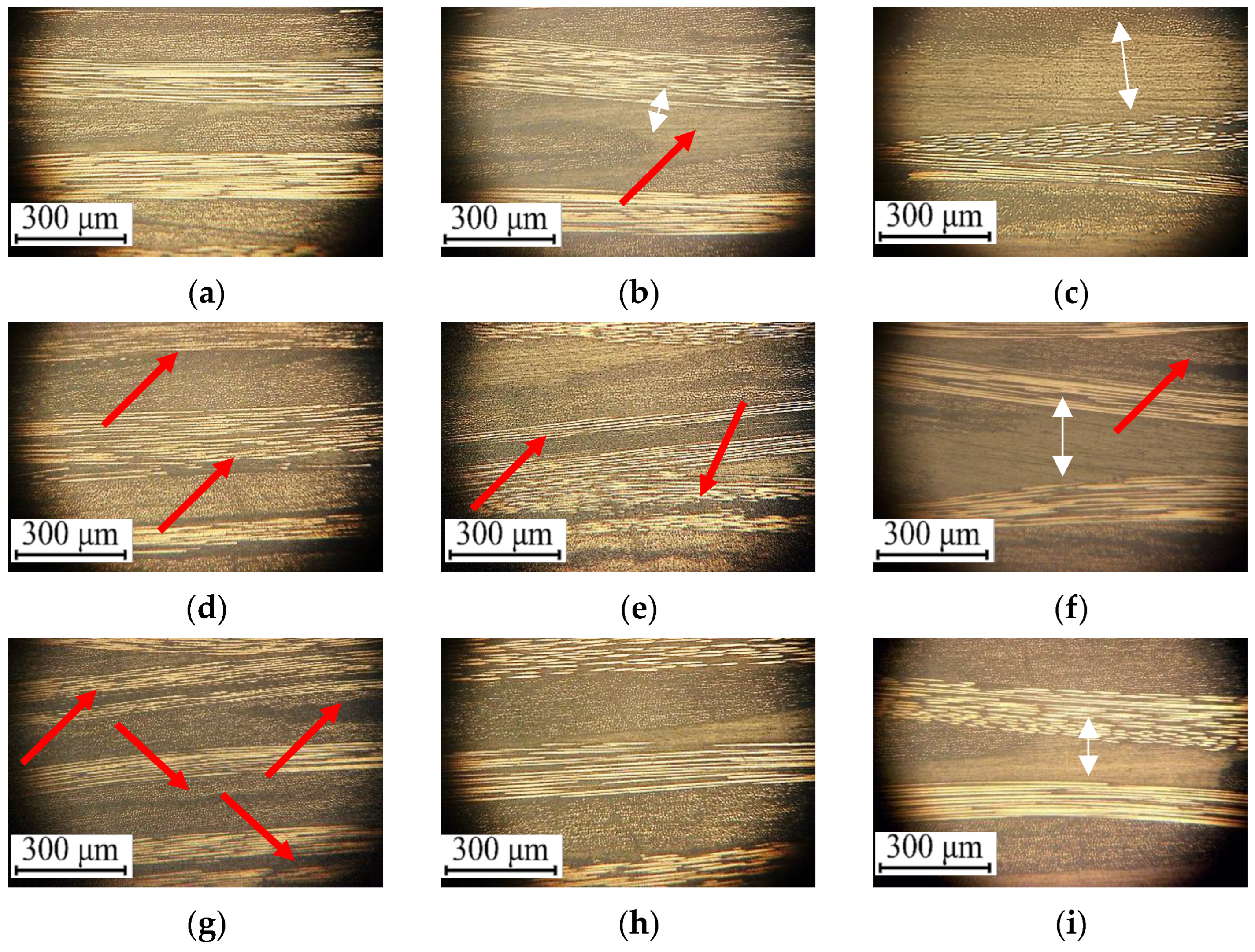
The OM images of the cross-sections of the composites: (a)—PEI30FW; (b)—PEI41FW; (c)—PEI70FW; (d)—PEI28PW; (e)—PEI39PW; (f)—PEI59PW; (g)—PEI30DW; (h)—PEI53DW; (i)—PEI64DW.
3.3. Interlayer Structures of the Composites
Figure 12 shows OM images of the interlayer structures of the studied composites. At the maximum CF fabric content (Figure 12a,d,g), the composite fabricated by film lamination (Figure 12a) exhibited the most homogeneous structure with similar thicknesses of the CF fabric layers of ~250 μm and uniform penetration of the binder into CF bundles. No discontinuities were observed, either at the interfaces between layers or within them. As expected, this pattern corresponded to the maximum strengths and elastic moduli recorded upon both three-point bending and tensile tests.
In the composites fabricated by powder lamination, some discontinuities were found at the interfaces between layers (shown with red arrows in Figure 12d). They did not resemble cracks, but rather microchips formed during the polishing of the composite surfaces for the OM examinations. However, it is suggested that these discontinuities could be responsible for the reduction in both flexural modulus and flexural strength (Figure 7).
For the impregnation with the dissolved polymer, the interlayer structures were characterized by the presence of multiple delaminations, primarily within the CF fabric layers (shown by red arrows in Figure 12g). This phenomenon was likely caused by either residual stresses or damage to the CF fabric fragments upon compression sintering. In the latter case, the reason could be the excessive pressure of melted polymer (due to bulk impregnation by dissolved PEI with lower viscosity). While film or powder lamination required greater pressures to penetrate the molten polymer into CF bundles, those levels could exert both the above-mentioned types of damaging effects on the CF fabrics impregnated with the PEI/NMP solution (this phenomenon is analyzed below in Section 4).
At medium CF fabric contents (Figure 12b,e,h), the interlayer structures of the composites fabricated by film lamination were the most uniform. However, due to the large number of PEI films (to increase the binder contents) placed between the CF fabric layers, some neat polymer discontinuities were observed at the interfaces (shown by an arrow in Figure 12b). These stimulated lower resistance to the applied loads, so both elastic moduli and ultimate strengths decreased (Figure 7 and Figure 10). It should be noted that discontinuities at the interfaces between layers additionally deteriorated the mechanical properties of the composites fabricated by powder lamination.
The functional characteristics of the composites fabricated by impregnation with the dissolved polymer were generally comparable to those of the other two applied methods (Figure 7 and Figure 10). The key reason was less damage to the CF fabric, as shown in Figure 12h.
At the minimal CF fabric contents, an “inversion” of the mechanical properties of the composites was observed. For example, the ones impregnated with the dissolved polymer exhibited both higher elastic moduli and ultimate strengths (Figure 7 and Figure 10). According to the OM images shown in Figure 12c,f,i, this fact could be explained by the following reasons. In the composites formed by film lamination, the thicknesses of the above-mentioned neat polymer discontinuities became comparable to those of the CF fabric layers (Figure 12c). They did not fail during the mechanical tests but were unable to provide adequate resistance to the applied loads in either the elastic or inelastic regions (when determining the elastic moduli and the ultimate strengths, respectively). For powder lamination, this phenomenon was additionally complicated by the presence of discontinuities (including delaminations) at the interfaces between the CF fabric layers or within them (indicated by an arrow in Figure 12f). Such discontinuities were significantly thinner after impregnation with the dissolved polymer (Figure 12i), as the higher polymer contents in the composites were achieved through more complete filling of CF bundles. Consequently, the PEI contents were more balanced at the interfaces between the layers.
4. Discussion
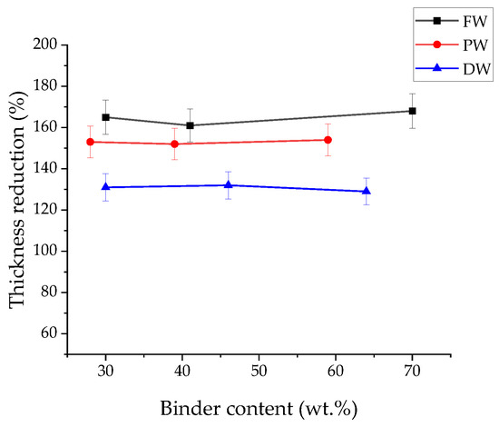
Several aspects of the above-described results deserve to be discussed. Firstly, the composites fabricated by film lamination exhibited the highest mechanical properties at the low binder contents (when the thicknesses of the adjacent binder and reinforcing layers were similar). This phenomenon was caused by several factors. Most importantly, the used PEI film was specifically designed for the manufacturing of composites, primarily in terms of the melt flow index (MFI) selection. So, the molten polymer had gradually impregnated the CF fabric fragments without damaging them upon compression sintering. Moreover, CF bundles were bulk impregnated as well (Figure 12a). In addition, the gradual spreading of the molten polymer upon compression sintering from the interlayer interfaces both reduced its contents in the composites and minimized the presence of discontinuities (delaminations), both at the interfaces between layers and within the CF fabric fragments. According to Figure 13, the composite thicknesses of 160–170 µm were almost similar before and after compression sintering for the ones fabricated by film lamination, but varied greatly for the other applied methods.
Figure 13.
The dependences of the composite thicknesses before and after compression sintering for both fabricating methods and component ratios.
Secondly, the thickness variation within the range of 152–154 µm was also virtually independent of the component ratio for powder lamination (Figure 13). However, a characteristic feature of all composites fabricated by this method was the presence of delaminations (Figure 12d–f). It is suggested that this phenomenon was caused by the spreading of the molten polymer within the CF fabric fragments. The powder melted faster than the film due to its dimensional parameters. As a result, the reinforcing component was sufficiently impregnated with the molten PEI, including within the CF bundles. Since compression sintering of all fabricated composites was performed at the same pressure, some CF fabric fragments could be damaged, deteriorating the mechanical properties. As evidenced in Figure 13, the thickness reduction was slightly less for powder lamination than when using the PEI film. A reason could be the fact that molten PEI impregnated the CF fabric fragments unevenly and squeezed off partly from the mold openings.
It should be noted that the authors used the commercially available PEI powder with an MFI of 9 g/10 min (340 °C/6.6 kg). Presumably, with a more appropriate selection of both MFI and compression sintering pressure and temperature, the number of discontinuities in the composites could be reduced. At least, the tensile elastic modulus of the samples fabricated by powder lamination with the maximum CF content was slightly higher than that of the film-based analog (Figure 10a).
After impregnation with the dissolved polymer, the results deteriorated greatly. The CF fabric was initially impregnated with PEI, so the viscous molten binder had to overcome the resistance of interwoven CF bundles upon compression sintering, which resulted in their damage (Figure 12g). Furthermore, the PEI contents were minimal at the interfaces between layers, reducing the adhesive strengths. This conclusion was consistent with the fact that the change in the composite thicknesses before and after compression sintering was minimal (129–132 µm, according to Figure 13). Since the compression sintering pressure was the same for all three applied methods, the increased number of discontinuities in the composites fabricated by impregnation with the dissolved polymer (with the highest CF fabric contents) was the main reason for the significant reduction in their both flexural and tensile strength properties (Figure 7 and Figure 10).
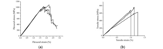
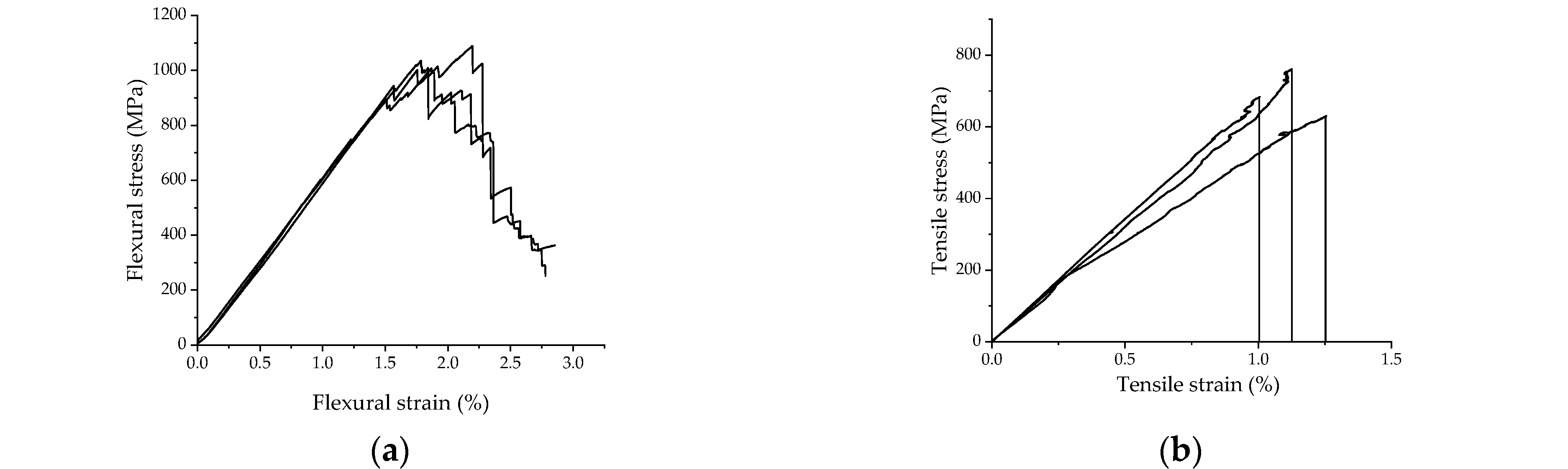
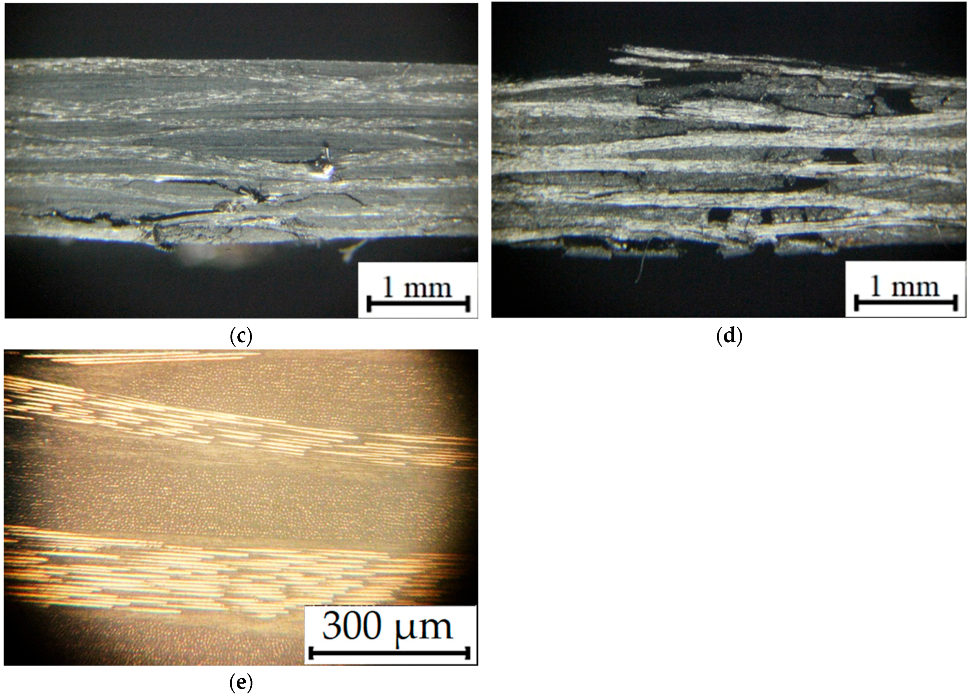
Based on the above, it was proposed to reduce the compression sintering pressure for the production route on impregnation with the dissolved polymer to minimize the possibility of damage to the CF fabric fragments by the viscous PEI flow. In such a case, residual stresses could be decreased as well. For this purpose, a new composite was fabricated by this method with a PEI/CF fabric ratio of 36/64, taking into account the suggested idea. The key difference in the applied parameters was a reduction in the compression sintering pressure down to 6 MPa. Then, it was examined in the same way as those described above. The corresponding stress-strain diagrams are shown in Figure 14a,b, while the main mechanical properties are summarized in Table 2.
Figure 14.
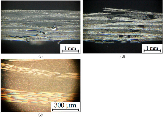
The stress-strain diagrams recorded in the three-point bending (a) and tensile (b) tests; the OM images of the cross-sections of the improved composite after the three-point bending (c) and tensile (d) tests, as well as its structure at the interfaces between layers (e).
Table 2.
The mechanical properties of the improved composite PEI36DW.
A comparison of these data with the results presented in Figure 7 and Figure 10 enabled the conclusion that the flexural strength of the improved composite exceeded that of the ones fabricated by film lamination, while their tensile strengths were almost the same. According to OM images of the cross-sections of the improved composite after the mechanical tests (Figure 14c,g), the failure modes were also similar to those of the ones fabricated by film lamination; this was true for the bending test (Figure 8a) and, to a lesser extent, in tension (Figure 11a). The structure of the improved composite, including at the interfaces between layers (Figure 14d), was more uniform than that described above (Figure 12g), significantly enhancing its mechanical properties. Moreover, reliable penetration of the binder within CF bundles was an important factor.
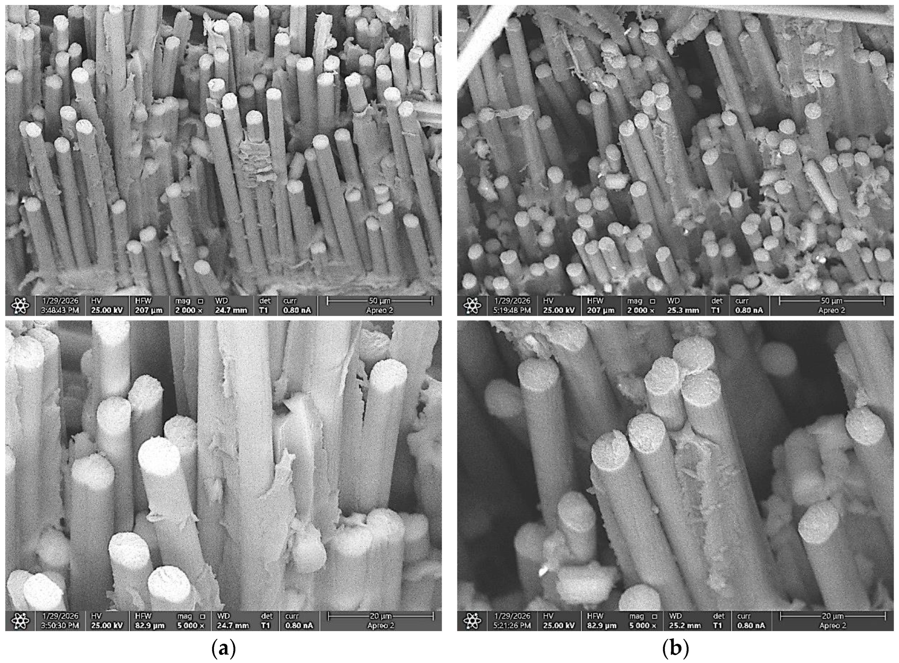
Figure 15 shows SEM micrographs of the fracture surfaces of the samples after the tensile tests. Impregnation with the dissolved polymer ensured the maximum PEI penetration between CF bundles (Figure 15a). This pattern was comparable with that after film lamination (Figure 15b), reflecting the above data on the mechanical properties of the composites fabricated by both methods and confirming the proposed null hypothesis of this study.
Figure 15.
The SEM–micrographs of the fracture surfaces on the composites fabricated by different methods after the tensile tests: (a)—PEI36DW; (b)—PEI30FW.
The most important technological outcome of the study is related to establishing a combination of process parameters that are responsible for the fabrication of laminates with CF-fabric impregnated with the dissolved PEI. It is economically efficient as well. The scientific novelty of the obtained results is related to pointing out a narrow technological window being a rational combination of “temperature-pressure-time” when control of the melted polymer matrix made it possible: (i) not to damage the reinforcing fabric, (ii) ensure high interlayer adhesion, and (iii) keep the specified ratio of components in the layered composite (laminate). This might be realized within a wide range of the matrix weight fraction of 30–60%.
Finally, it should be noted that impregnation with the dissolved polymer is a cost-effective method and requires lower specific pressure upon compression sintering of composites. It ensures the penetration of polymer binders into CF bundles, minimizing the number of discontinuities, which is especially important when manufacturing three-dimensional complex-shaped parts. It is also worth emphasizing the preservation of the functional characteristics of the polymer binders after the solvent evaporation. This fact is evidenced by both bending and tensile mechanical properties.
Further research in this area should involve tests on interlaminar shear strength as well as cyclic testing, as the uniform distribution of components is one of the determining factors controlling fatigue life of such composites.
5. Conclusions
1. At the compression sintering pressure of 10 MPa, the most uniform structure with the minimum number of discontinuities was formed by film lamination with the maximum CF fabric content. The reason was the fact that the used commercially available PEI film is initially designed for manufacturing composites via such production routes, so its MFI value was efficient for impregnating CF bundles at the specified processing temperature. As a result, the maximum strength properties were achieved at the minimum binder content of 30 wt.%.
2. It is not recommended to fabricate composites by film lamination with low CF fabric contents, since an excessive number of binder layers leads to the formation of neat polymer voids, significantly reducing their both flexural moduli and strengths.
3. At powder lamination, some discontinuities were found in the composites, which may be caused by the low MFI of the PEI powder (9 g/10 min). In such cases, the molten polymer could damage CF bundles when spreading inside them (according to the presented OM images), reducing both elastic moduli and strengths to a certain extent.
4. Manufacturing composites by impregnation with dissolved polymers at high compression sintering pressures (~10 MPa), which improves productivity, is recommended only with low CF fabric contents, as it keeps significant amounts of the binders. Subsequent extrusion of the binders to reduce the polymer contents in the composites damages the CF fabrics, significantly reducing both elastic moduli and strengths.
5. Based on the preliminary research results, the compression sintering pressure after impregnation with the dissolved polymer was reduced to 6 MPa. The improved composite with the CF fabric content of 64 wt.% was characterized by the great strength properties (even higher than those after film lamination), confirming both the effectiveness of the proposed method and the positive effect of internal impregnation of CF bundles on the functional characteristics of the composite.
Author Contributions
Conceptualization, S.V.P. and V.O.A.; methodology, S.V.P. and V.O.A.; validation, V.O.A. and Z.P. formal analysis; V.O.A. and Z.P.; investigation, Z.P., V.O.A., A.A.B., S.L. and D.G.B.; resources, S.V.P.; data curation, Z.P. and V.O.A.; writing—original draft preparation, S.V.P., Z.P. and V.O.A.; writing— review and editing, S.V.P. and S.L.; visualization, V.O.A. and Z.P.; funding acquisition, Z.P. and S.V.P. All authors have read and agreed to the published version of the manuscript.
Funding
The study was carried out within the framework of the state assignment of the Institute of Strength Physics and Materials Science SB RAS, project FWRW-2026-0008.
Data Availability Statement
The data presented in this study are available in this article.
Acknowledgments
The SEM examinations were performed using equipment of the "Nanotech" shared use center of the Institute of Strength Physics and Materials Science SB RAS and the core facility “Structure, mechanical and physical properties of materials” NSTU.
Conflicts of Interest
The authors declare no conflicts of interest.
Abbreviations
The following abbreviations are used in this manuscript:
| CF | Carbon fiber |
| CFRPCs | Carbon fiber reinforced polymer composites |
| HPTRs | High-performance thermoplastic resins |
| PEI | Polyetherimide |
| NMP | N-methylpyrrolidone |
| PEI PW | Polyetherimide powder |
| PEI FW | Polyetherimide film |
| PEI DW | Polyetherimide powder dissolved in N-methylpyrrolidone |
| OM | Optical microscope |
| MFI | Melt flow index |
References
- Shaharear, M.E.; Pitto, M.; Šimáček, P.; Advani, S.G. Role of fiber clustering and resin bleeding on voids and evolution of fiber volume fraction for additively manufactured continuous carbon fiber thermoset composites with dual-cure resins. Compos. Part A Appl. Sci. Manuf. 2025, 189, 108601. [Google Scholar] [CrossRef] [Scilit]
- Zhou, J.Q.; Zhu, B.; Zhao, W.; Zhang, Y.; Li, J.L.; Fan, J.Y.; Qiao, K. Enhancement of interfacial performance of carbon fiber reinforced polypropylene composites by dual action of polyetherimide nanoparticles and coatings. Colloids Surf. A Physicochem. Eng. Asp. 2024, 689, 133776. [Google Scholar] [CrossRef] [Scilit]
- Ali, M. Thermosetting polymer composites: Manufacturing and properties study. Rev. Adv. Mater. Sci. 2023, 62, 20230126. [Google Scholar] [CrossRef] [Scilit]
- Li, Y.; Roh, H.D. Recent Advances in Joining of Fiber-Reinforced Polymer Composites: A Review on Thermoset and Thermoplastic Matrices. Int. J. Precis. Eng. Manuf.-Green Technol. 2025. [Google Scholar] [CrossRef] [Scilit]
- Frank, E.; Steudle, L.M.; Ingildeev, D.; Spörl, J.M.; Buchmeiser, M.R. Carbon Fibers: Precursor Systems, Processing, Structure, and Properties. Angew. Chem. Int. Ed. 2014, 53, 5262–5298. [Google Scholar] [CrossRef] [Scilit]
- Kim, Y.H.; Kumar, S.; Li, X.; Kim, S.Y.; Shin, D. Temperature-dependent mechanical properties and material modifications of carbon fiber composites for optimized structures in high-end industrial applications. Compos. Part B-Eng. 2025, 303, 112602. [Google Scholar] [CrossRef] [Scilit]
- Toro, S.A.; González, C.; Fernández-Blázquez, J.P.; Ridruejo, A. Fabrication and mechanical properties of a high-performance PEEK-PEI hybrid multilayered thermoplastic matrix composite reinforced with carbon fiber. Compos. Part A Appl. Sci. Manuf. 2024, 185, 108308. [Google Scholar] [CrossRef] [Scilit]
- Wang, J.; Wang, A.D.; Ding, Z.J.; Wang, C.Y.; Liu, J.N. Design, Preparation and Crystallization Behavior of Carbon Fiber Reinforced Hybrid Resin Matrix Composite Laminates. Polym. Compos. 2026, early view. [Google Scholar] [CrossRef] [Scilit]
- Mccrickard, C.; Boyd, A.; Archer, E.; Manzoor, F.; Ullah, J. Polyether ether ketone (PEEK) and polyetherimide (PEI) for fused filament fabrication (FFF) in medical applications. Int. J. Adv. Manuf. Technol. 2025, 140, 5737–5754. [Google Scholar] [CrossRef] [Scilit]
- Kothavade, P.; Kafia, A.; Shanmuganathanb, K.; Bateman, S. High performance polyimides for additive manufacturing: A critical Review. Progress in Polymer Science. Prog. Polym. Sci. 2026, 172, 102005. [Google Scholar] [CrossRef] [Scilit]
- Baran, I.; Cinar, K.; Ersoy, N.; Akkerman, R.; Hattel, J.H. A review on the mechanical modeling of composite manufacturing processes. Arch. Comput. Methods Eng. 2017, 27, 365–395. [Google Scholar] [CrossRef] [Scilit]
- Hejjaj, C.; Scharnagl, N.; Lamaka, S.V.; Fischer, C.B.; Zheludkevich, M.L. Highly efficient anti-corrosion polyetherimide (PEI) coating encapsulated with aluminum di-hydrogen tri-polyphosphate. Surf. Interfaces 2024, 46, 104098. [Google Scholar] [CrossRef] [Scilit]
- He, H.W.; Zeng, X.Q.; Peng, X.J.; Ma, M.; Shi, Y.Q.; Zhu, Y.L.; Shi, H.B.; Jiang, X.P.; Chen, S.; Wang, X. Improving the thermal conductivity of PEEK composites with PEI-assisted dispersion of carbon-based fillers. High Perform. Polym. 2025, 37, 403–415. [Google Scholar] [CrossRef] [Scilit]
- Garcea, S.C.; Wang, Y.; Withers, P.J. X-ray computed tomography of polymer composites. Compos. Sci. Technol. 2018, 156, 305–319. [Google Scholar] [CrossRef] [Scilit]
- Goda, I.; Padayodi, E.; Raoelison, R.N. Enhancing fiber/matrix interface adhesion in polymer composites: Mechanical characterization methods and progress in interface modification. J. Compos. Mater. 2024, 58, 3077–3110. [Google Scholar] [CrossRef] [Scilit]
- Pourahmadi, E.; Shadmehri, F.; Ganesan, R. Interlaminar shear strength of Carbon/PEEK thermoplastic composite laminate: Effects of in-situ consolidation by automated fiber placement and autoclave re-consolidation. Compos. Part B Eng. 2024, 269, 111104. [Google Scholar] [CrossRef] [Scilit]
- Bai, Q.Y.; Hao, Q.; Dai, H.Q.; Chen, Y.W.; Dai, N. A review on integrated design and manufacturing technologies for continuous fiber-reinforced polymer composite lightweight structures in aerospace. Thin-Walled Struct. 2025, 217, 113750. [Google Scholar] [CrossRef] [Scilit]
- Valente, M.; Rossitti, I.; Sambucci, M. Different Production Processes for Thermoplastic Composite Materials: Sustainability versus Mechanical Properties and Processes Parameter. Polymers 2023, 15, 242. [Google Scholar] [CrossRef] [Scilit]
- Yang, Z.T.; Fang, Y.P.; Zeng, J.J.; Liu, Y.; Zhang, Z.; Li, C.; Cao, X.W. Blow molding liquid crystal aromatic polyester/polyetherimide film by rotating die: Enhanced film bubble stability and mechanical properties. Polym. Adv. Technol. 2024, 35, e6281. [Google Scholar] [CrossRef] [Scilit]
- Wang, W.C.; Zhang, J.D.; Gao, D.T.; Yu, K.; Liu, G.; Wang, M.; Yao, J.A. The Effect of Resin Matrix on the Properties of CF/PEI and CF/PAEK Thermoplastic Composites. Int. J. Polym. Sci. 2023, 2023, 8407907. [Google Scholar] [CrossRef] [Scilit]
- Chen, W.T.; Zhang, K.; Wang, S.; Wang, S.Y.; Chen, C.H.; Zhao, X.G.; Zhou, H.W.; Wang, D.M. Construction of an interphase with heat and solvent resistance by a waterborne self-crosslinking polyamide-imide sizing agent to enhance the interfacial and mechanical performance of CF/PEEK composites. Compos. Part B Eng. 2026, 312, 113330. [Google Scholar] [CrossRef] [Scilit]
- Huo, H.Y.; Yao, X.; Gao, L.; Zhou, D.R.; Wu, T.Y.; Zhang, B.Y. Research progress in preparation technology of high performance continuous fiber reinforced thermoplastic prepreg and its composites. Cailiao Gongcheng 2025, 53, 44–53. [Google Scholar] [CrossRef]
- Vakharia, V.S.; Leonard, H.; Singh, M.; Halbig, M.C. Multi-Material Additive Manufacturing of High Temperature Polyetherimide (PEI)-Based Polymer Systems for Lightweight Aerospace Applications. Polymers 2023, 15, 561. [Google Scholar] [CrossRef] [Scilit]
- de Carvalho, G.B.; Costa, P.E.; de Morais, L.C.; Pasquini, D. Preparation of Polymeric Membranes and Application as an Interdisciplinary Investigative Proposal for Teaching Chemistry. Rev. Virtual Quim. 2023, 15, 1138–1147. [Google Scholar] [CrossRef] [Scilit]
- Panin, S.V.; Bogdanov, A.A.; Aleksenko, V.O.; Bochkareva, S.A.; Lyubutin, P.S.; Panov, I.L.; Tian, D. Digital Image Correlation Analysis of Fatigue Degradation of Layered Polymer Composites (Polyetheretherketone/Polyetherimide, PEEK/PEI) with Carbon-Fiber Fabric Prepreg. Phys. Mesomech. 2024, 27, 541–555. [Google Scholar] [CrossRef] [Scilit]
- Liu, Y.Q.; Ge, S.Y.; Qi, D.S.; Meng, L.C.; Jiang, Y.R.; Jiang, M.T.; Zhao, S.; Wang, S.; Yue, X.G. Outstanding Impact Resistance of Poly(ether-ether-ketone) Reinforced by Polyetherimide-Modified Long Carbon Fiber via Solution Impregnation. J. Appl. Polym. Sci. 2026, 143, 70584. [Google Scholar] [CrossRef] [Scilit]
- McLaughlin, J.W.; Tobin, E.; O’Higgins, R.M. An investigation of Polyether Imide (PEI) toughening of carbon fibre-reinforced Polyether Ether Ketone (PEEK) laminates. Mater. Des. 2021, 212, 110189. [Google Scholar] [CrossRef] [Scilit]
- Rattan, R.; Bijwe, J. Carbon fabric reinforced polyetherimide composites: Influence of weave of fabric and processing parameters on performance properties and erosive wear. Mater. Sci. Eng. A 2006, 420, 342–350. [Google Scholar] [CrossRef] [Scilit]
- Lu, Y.H.; Zhan, M.S.; Zheng, W.H. Preparation and properties of T300 carbon fiber-reinforced thermoplastic polyimide composites. J. Appl. Polym. Sci. 2006, 102, 646–654. [Google Scholar] [CrossRef] [Scilit]
- ASTM D3039; Standard Test Method for Tensile Properties of Polymer Matrix Composite Materials. ASTM International: West Conshohocken, PA, USA, 2014. Available online: https://store.astm.org/d3039_d3039m-08.html (accessed on 20 April 2026).

Disclaimer/Publisher’s Note: The statements, opinions and data contained in all publications are solely those of the individual author(s) and contributor(s) and not of MDPI and/or the editor(s). MDPI and/or the editor(s) disclaim responsibility for any injury to people or property resulting from any ideas, methods, instructions or products referred to in the content. |
© 2026 by the authors. Licensee MDPI, Basel, Switzerland. This article is an open access article distributed under the terms and conditions of the Creative Commons Attribution (CC BY) license.