


Highlights
What are the main findings?
- Design of a hybrid powertrain comprising a Li-ion battery pack and a hydrogen fuel cell range extender unit.
- Development of a rule-based control strategy for the proposed configuration with a view to effectively extend endurance without affecting durability.
- Experimental tests of the proposed powertrain on an agricultural rover prototype showed significant improvements in the rover endurance.
What are the implications of the main findings?
- The implementation of hydrogen fuel cells could be a feasible path to extend the endurance of agricultural rovers, maintaining zero local emissions and without implementing bulky energy storage systems.
Abstract
Agriculture plays a relevant role in the food supply chain but is also a major contributor in terms of emissions. A possible solution to reduce its impact is to replace traditional machinery with innovative systems, such as agricultural rovers. In the proposed research, a case study of an agricultural rover, specifically designed to operate in orchards, is presented. The powertrain features a Li-ion battery pack as the primary energy source and a fuel cell system operating as a range extender unit. Hydrogen is stored on board using a metal hydride tank to enhance compactness. Once the traction and range extender power output control strategies were defined, experimental tests in a closed warehouse were performed. During the tests, the rover was manually controlled using a joystick, since the main focus was to evaluate the powertrain behavior rather than to test the autonomous driving algorithm. During the tests, different maneuvers in narrow spaces were performed. The results showed that the rover successfully accomplished the tasks and the range extender unit can effectively extend the rover autonomy up to +150% compared to the pure battery solution. This result was obtained considering a 15 min test carried out in an indoor environment with a polished concrete floor.
1. Introduction
In recent years, a large amount of attention has been given to the influence of anthropic activities on economics, human health and the environment [1,2,3,4]. In this scenario, agricultural practices contribute significantly to emissions, including greenhouse gases and pollutants [5]. At the same time, agriculture plays a key role in the food supply chain and must meet the demands of a growing global population [6]. Consequently, it is crucial to improve sustainability without affecting productivity.
Sustainability can be enhanced in different ways [7,8]. From a technical point of view, to reduce tailpipe emissions, several techniques involving the adoption of exhaust gas aftertreatment systems can be exploited [9]. Other solutions, instead, are related to the use of non-conventional fuels, for example, biogas and biodiesel, to substitute traditional diesel to propel the vehicle [10,11,12]. Biodiesel and biogas can reduce the environmental footprint compared to traditional diesel; however, their use can cause a reduction in engine performance [13]. A feasible path to effectively reduce sector-related emissions consists of replacing traditional machineries with more efficient and innovative systems [14,15,16,17]. Indeed, different studies have demonstrated that the adoption of hybrid/electric, pure battery and hybrid fuel cell powertrains can reduce the environmental footprint of vehicles [18,19,20,21,22]. Full electric machineries locally produce almost zero emissions, but the limited endurance related to the limited energy density of batteries can be a limiting factor that prevents their widespread diffusion [23]. On the contrary, hybrid solutions with downsized thermal engines can improve sustainability without compromising productivity [24], however, the environmental benefits can be lower compared to other solutions [25]. Hybrid fuel cell powertrains can achieve both zero local emission levels and productivity requirements [26,27], making them a solution with a lower impact compared to hybrid systems with internal combustion engines [28], but without the issues related to the low endurance of pure battery powertrains. Despite the promising benefits, the environmental performance of hydrogen-powered vehicles is strictly correlated with how hydrogen is produced. At present, more than 60% of the total hydrogen production is obtained from steam methane reforming, a process with a significant associated carbon footprint [29]. Indeed, according to estimations, the direct greenhouse gas emissions for the production of hydrogen through steam methane reforming are estimated to be more than 9 kgCO2,eq/kgH2 [30]. Hydrogen is characterized by a higher heating value of 39.4 kWh/kg and a lower heating value of 33.3 kWh/kg. For comparison, diesel fuel and gasoline are characterized by a higher heating value of 12.67 kWh/kg and 12.89 kWh/kg respectively. Nevertheless, hydrogen can also be obtained using processes with low associated emissions, such as through water electrolysis, or through traditional methods with carbon capture technologies [31,32]. The adoption of less impactful methods has been increasing in recent years and is expected to reach a significant quota in the future [33]. Considering the current state of the art, the most significant barriers to the widespread adoption of fuel cell systems are related to high cost [34], durability [35], lack of infrastructure for hydrogen supply [36], and people’s negative perceptions about the cost-effectiveness and the environmental benefits of using hydrogen [37].
The substitution of traditional machinery, however, can occur at different levels. A first approach can be to replace only the powertrain, while maintaining the chassis and the power capability. A further step, instead, involves replacing the entire machine. In detail, for low-power field tasks, traditional agricultural vehicles can be substituted with autonomous rovers [38], that can complete the mission with a higher efficiency due to their limited weight and size. Agricultural rovers, depending on their design, can perform a wide range of tasks, including field operations, crop health monitoring, and disease detection [39,40]. In addition, they can enhance precision farming practices by optimizing resource utilization [41]. Due to their properties, the market size of agricultural robots has been increasing in recent years. According to recent market forecasts, their market is expected to expand from USD 17.73 billion in 2025 to more than USD 56 billion in 2030, with a compound annual growth rate of 26%, with Europe and North America the most relevant regions from a geographical point of view [42]. Taking a look at the current availability on the market, it can be stated that most of the agricultural robots are powered with a full electric powertrain, while only a small part is equipped with a thermal engine [43]. The predominance of electric systems may be related to different factors, including zero local emissions, higher efficiency and ease of implementation, and they are particularly suitable for small and medium-size robots. Hybrid powertrains with a thermal engine are less common and usually adopted on larger robots, such as the AgBot developed by AgXeed [44]. The adoption of a full electric powertrain, however, can be critical in terms of endurance. Consequently, to improve the expected working time, some robots are equipped with integrated solar panels [45]. Although in some circumstances they can be a promising strategy to extend endurance, the power output of solar panels is directly affected by weather and environmental conditions, thus, in case of clouds or dust accumulation, the performance can be significantly lower [46]. In this context, hybrid fuel cell systems may be an interesting solution to improve the endurance of agricultural robots. At present, to the authors’ knowledge, there are no commercially available robots with hydrogen fuel cell technologies. In addition, the scientific literature lacks studies. A concept of an agricultural robot with a fuel cell unit was analyzed with a numerical approach by Ghobadpour et al. [47], with a view to evaluate the endurance improvements compared to the pure electric solution. A robotic tractor with a fuel cell system was considered in [48], demonstrating a reduction of almost 50% of the emissions. However, no other relevant studies were found. In addition, agricultural robots differ considerably across applications, thus the existing studies cover only a small fraction of the potential application spectrum.
In the present study, a prototype of an autonomous driving rover designed for orchards and vineyards is experimentally tested. This rover, called Smilla H2, was developed by the Italian company Ecothea (Ecothea Srl, Turin, Italy) and was specifically designed to operate in orchards and vineyards [49,50]. The rover is equipped with a hybrid powertrain featuring a battery pack as a primary energy source and a fuel cell system as a range extender. To improve compactness, hydrogen is stored in a metal hydride tank. Compared to high-pressurized type IV tanks, metal hydride solutions operate at lower pressures and can exhibit a higher volumetric energy density (up to five times) [51]. On the contrary, their gravimetric energy density is lower, usually 1/2 or 1/3, thus they are of particular interest in those applications where compactness is more crucial than overall weight [52].
The research activity focused on the integration of the range extender unit on board the vehicle, the development of a proper control strategy and the testing of the powertrain during significative work maneuvers in order to evaluate the benefits in terms of endurance extension by comparing it with the pure battery configuration. Since the main focus was to investigate the powertrain behavior, the rover was manually controlled using a joystick instead of operating using the autonomous driving algorithm. The present paper is organized as follows: Section 2, Materials and Methods, illustrates the rover case study, describing the powertrain architecture, the rover mechanical properties, the powertrain control strategy, and the experimental test conditions; Section 3, Results and Discussion, presents a discussion of the results of the experimental analysis; lastly, Section 4, Conclusions, summarizes the main findings of the paper.
2. Materials and Methods
In this section, the rover under investigation is presented and described. The hybrid powertrain configuration is then detailed, with a focus on the main components and their features. Next, a description of the control strategy is provided. Lastly, the test conditions for the experimental tests are outlined.
2.1. Case Study: Smilla H2
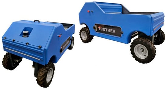
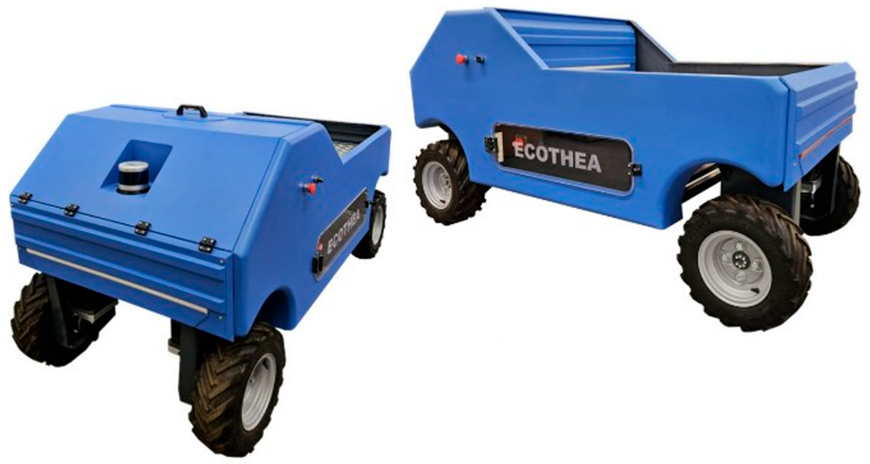
The rover examined in this study is the Smilla H2 prototype, developed and presented by the Italian company Ecothea Srl. The vehicle has been patented (WO 2026/013619) [53]. This rover is an autonomous driving rover equipped with several sensors and systems to perform different field tasks. A picture of the rover is shown in Figure 1, whereas its main characteristics are presented in Table 1. The vehicle is intended for orchards and vineyards and adopts a four-fixed-wheels configuration. Each wheel is connected to a dedicated electric motor through a planetary gear reducer characterized by a transmission ratio of 12:1. The rated efficiency of the reducer is equal to 90% as declared by the manufacturer. Each electric motor has a rated power of 1.2 kW and can provide 5 Nm of continuous torque and up to 15 Nm of peak torque according to S3-20% service. S3-20% indicates that the motor is capable of delivering the peak torque continuously for 2 min on a duty cycle of 10 min total.
Figure 1.
Smilla H2 prototype.
Table 1.
Smilla H2 main properties.
The main on-board energy source is represented by a Li-ion battery pack (BP). The BP consists of 16 lithium iron phosphate (LFP) cells, each one with a rated capacity of 105 Ah and a rated voltage of 3.2 V, connected in series to reach an overall rated voltage of 51.2 V. The battery pack was dimensioned to deliver, at a 1C discharge rate, a power output comparable to the combined rated power of the motors. To monitor cell voltage and perform their balancing, a BMS is implemented. In addition, the BMS monitors the battery pack temperature, through three temperature transducers, and the BP actual current. If the temperature or current exceeds the threshold values of 65 °C and 150 A respectively, the BMS disconnects the positive pole of the pack as a safety measure.
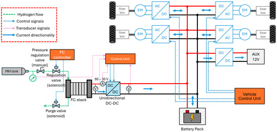
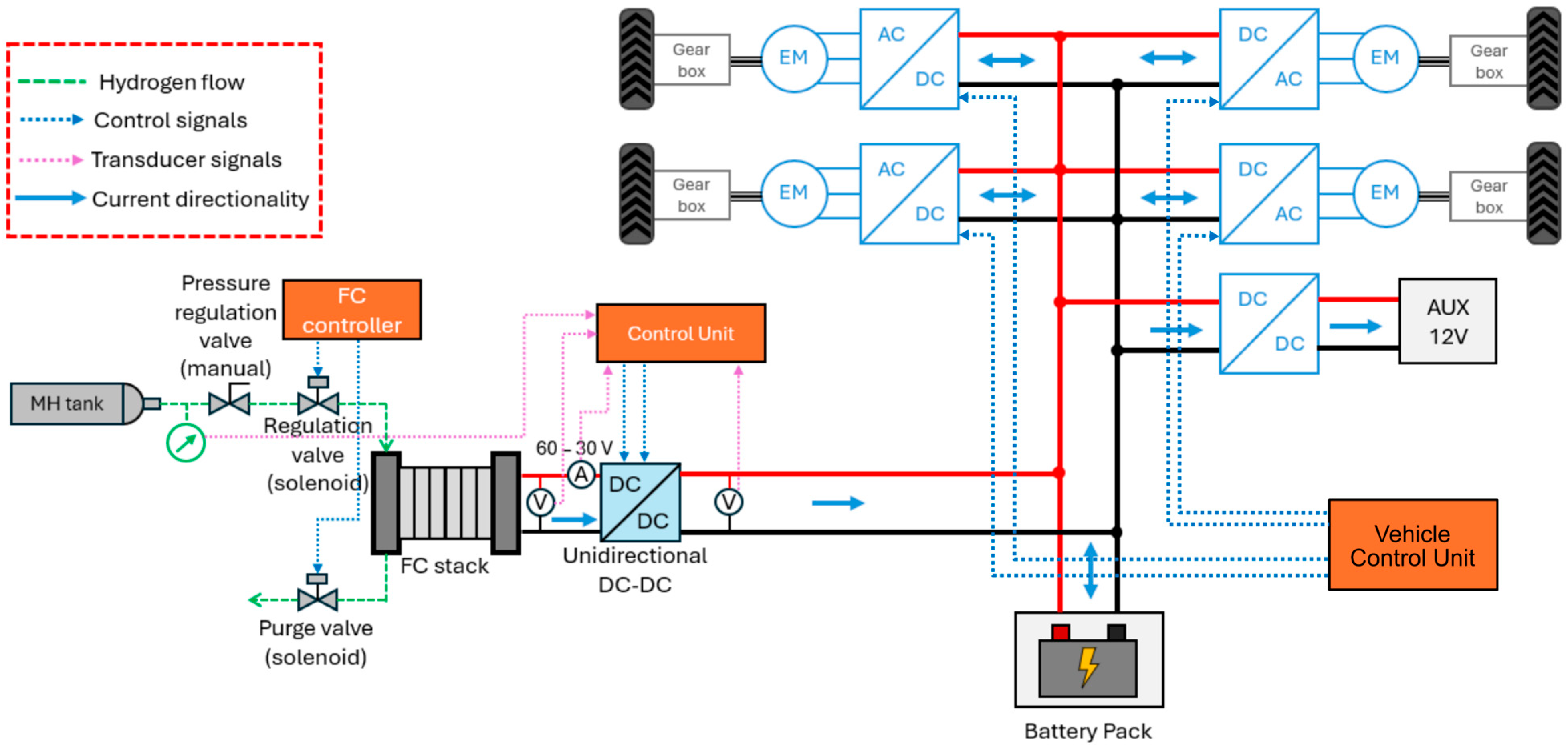
As for the range extender unit, it is composed of the FCS-C300 fuel cell system, manufactured by Horizon (Horizon Fuel Cell Technologies, Singapore), which is an open-cathode polymer electrolyte membrane fuel cell (PEMFC) with a dedicated controller, a metal hydride (MH) tank, a controllable DC-DC converter to interface the fuel cell output with the DC bus voltage, and an integrated control unit that monitors the main operational parameters and controls the power output. The DC-DC acts as a power conditioning unit and is used to regulate the unit power output [54]. The MH tank has a hydrogen capacity of 80 g and an internal volume of 1.7 liters and weighs 7 kg. To operate, the range extender unit must be supplied with 12 V, which is obtained from the BP using an auxiliary DC-DC converter with a fixed output. The MH tank supplies hydrogen to the fuel cell inlet through a manual pressure-reducing valve and a solenoid valve. The first valve reduces the internal pressure of the tank to the proper value for the stack’s anode inlet. The second instead controls the hydrogen flow to the anode and is actuated by the fuel cell system controller. At the anode exhaust, a purge valve, also controlled by the controller, is placed. In addition, a pressure transducer is placed on the MH tank to monitor its internal pressure. Figure 2 illustrates a schematic layout of the powertrain, with a focus on the fuel cell range extender unit.
Figure 2.
Smilla H2 powertrain schematic layout. Auxiliaries (AUX) include sensors, the on-board control unit, the FC system controller, etc.
Table 2 reports the most relevant properties of the powertrain components. The choice of the range extender components, namely the FC system and the MH tank, was performed considering compactness as the main limiting factor. Indeed, the first version of the rover featured only the battery pack. The main idea of introducing the range extender unit was to extend the endurance without changing the overall dimensions or requiring relevant mechanical modifications. Due to the limited on-board space availability, the choice of a low-power stack and an MH tank was necessary to achieve satisfactory results. Furthermore, the MH tank was characterized by a lower internal pressure compared to gaseous tanks, which reduced risks associated with high-pressurized gases that might be critical in an application with significant stresses, such as agricultural vehicles. Compared to high-pressurized gaseous tanks, MH tanks generally require a higher investment cost, mainly due to their lower production volume and the high cost of their materials. In addition, the cost strictly depends on the adopted metal alloy and may vary significantly from one solution to another. Nevertheless, the lower internal pressure reduces the cost associated with hydrogen compression. Moreover, the MH tank pressure range generally matches the output pressure of electrolyzers. Consequently, in the case of long operational life, a significant part of the initial investment cost can be recovered [55]. Indeed, in the literature the energy required for hydrogen compression to 350 bar is around 10 MJ/kg for a big compressor and can be over 20 MJ/kg in the case of a small compressor or for 700 bar compression, even if more advanced solutions can reduce this value to less than 10 MJ/kg [56].
Table 2.
Smilla H2 powertrain main properties.
Once the maximum available volume was determined, the MH tank and the fuel cell system were chosen so that the unit can operate for 8 h straight with a power output of 80% the rated power.
The rover presents a main vehicle control unit (VCU), which controls the inverters, collects data from the sensors, and monitors the operational state of all the subsystems. The range extender unit presents its own control unit as described in Figure 2. The vehicle is equipped with an on-board controller area network (CAN) bus [57]. The CAN bus is used by the VCU to send commands to the inverters and to collect information from them about motors speeds, temperature and battery currents. The range extender control unit, specifically designed for this application, supports CAN communication and sends information periodically to the VCU about the actual tank internal pressure, FC voltage and current output, current setpoint and control signals to the DC-DC.
2.2. Fuel Cell Range Extender Unit Components
The fuel cell range extender unit is composed of the following elements:
- FC system.
- MH tank.
- Valves and tubes for hydrogen supply.
- Control unit.
- DC-DC converter.
- Transducers.
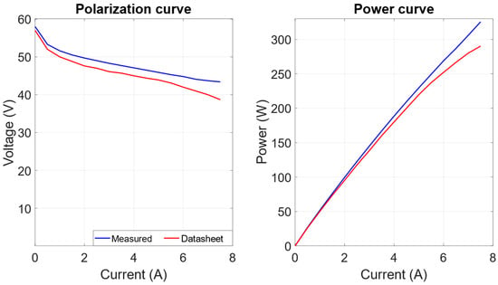
The adopted FCS-C300 fuel cell system is an open-cathode PEMFC composed of 60 cells and with a rated power output of 300 W. The actual polarization curve of the stack, obtained through experimental tests conducted at an ambient temperature of 25 °C and described in [58], is shown in Figure 3.
Figure 3.
Actual polarization curve of the FCS-C300 system.
From the figure, it can be noted that the stack showed better performance than those declared by the manufacturer, with peaks of +10%. During the characterization tests of the FCS-C300 system, the power absorbed by the controller ranged from 15 to 30 W depending on the actual stack temperature. Indeed, the blowers’ rotational speed was increased when temperature rose. In addition, the stack presented a short circuit unit (SCU) that was responsible for bringing, approximately every 10 s, the voltage level of the stack to zero and, after 0.1 s, back to the normal level [59]. The short circuit method is used to improve the performance of the stack over time by stripping of oxides and other adsorbed species from platinum [60].
As for the MH tank, hydrogen absorption and desorption processes can be described by the following reaction [61]:
where M is the metal alloy, H is hydrogen, x is hydrogen-to-metal ratio and Q is the heat absorbed/released during the desorption/absorption processes. Indeed, the desorption reaction is an endothermic process; thus, heat should be supplied to the tank. The absorption reaction is, instead, exothermic, and heat should be extracted from the tank. The equilibrium pressure can be described with the Van’t Hoff equation [62]:
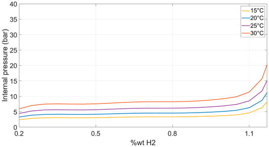
where peq is the equilibrium pressure, p0 the reference pressure (usually the atmospheric pressure), ΔH and ΔS are the enthalpy and entropy of the reaction respectively, Rg is the gas constant, and TMH is the temperature of the metal hydride. This equation describes the influence of temperature on the equilibrium pressure. At higher temperatures the equilibrium pressure is higher. It should be noted that the enthalpy and entropy of the reaction are different for the absorption and desorption processes, thus both should be characterized, and they are different depending on the metal hydride. Another parameter that significantly influences the equilibrium pressure is the actual hydrogen content. Indeed, to fully describe the equilibrium pressure, PCT curves are generally adopted [62,63]. These curves describe the pressure vs. hydrogen concentration at a certain temperature. From a mathematical point of view, the following equation can be used to describe the PCT curves:
where f(H/M) describes the equilibrium pressure trend at temperature Tref as a function of H/M, that is, the hydrogen-to-metal ratio. The PCT curve presents a typical trend according to which at low hydrogen concentrations the pressure changes significantly with the hydrogen content, then is characterized by a central zone with low variations, and then at high hydrogen concentrations a zone with again a strong dependence of pressure on hydrogen content [64]. Furthermore, the PCT curves of absorption and desorption processes are characterized by hysteresis, with the equilibrium pressure being higher in the first case. Lastly, the heat that should be supplied or extracted from the tank can be evaluated using the following equation [62]:
The MH tank adopted on the range extender unit was characterized as described in [58]. The attention focused on the desorption process as it is more critical for proper vehicle operation. Indeed, the internal pressure of the tank should always be enough to guarantee the hydrogen supply to the fuel cell stack anode. As a matter of fact, gas starvation can cause a reduction in fuel cell durability [65]. The results of the characterization of the hydrogen desorption process are shown in Table 3 and Figure 4. Accordingly, the heat absorbed by the tank with the fuel cell delivering its rated power was estimated around 100 W.
Table 3.
MH tank desorption process enthalpy and entropy of reaction.
Figure 4.
Experimental results for the PCT curves of the MH tank.
The DC-DC adopted to connect the stack to the DC bus was a buck–boost converter with analogue ports for the voltage and current setpoints. Table 4 summarizes the relevant characteristics of the device.
Table 4.
DC-DC main properties.
As for the current and voltage transducers, the range extender unit featured two current transducers, one placed at the stack output and the other at the DC-DC converter output, and two voltage transducers, one placed at the converter output to monitor the voltage level of the DC bus and the other at the fuel cell output. The adopted transducers were the CAS 6-NP (current) and the LV 25-P (voltage), produced by LEM (LEM International SA, Meyrin, Switzerland). To protect the stack from short circuits or inverse polarity, a fuse and a diode were placed between its output and the DC-DC input. The efficiency of the DC-DC and power circuit assembly was evaluated with dedicated tests. It was noted that at low input currents the efficiency was low. In detail, at a fuel cell current of 0.5 A it was 62%. However, it rapidly increased with the current, exceeding 90% at a fuel cell current of 1.75 A. At higher currents, the efficiency had a more stable trend and reached 94.5% at a fuel cell current of 7 A.
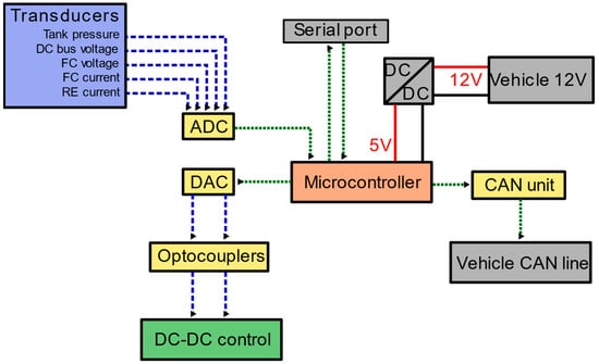
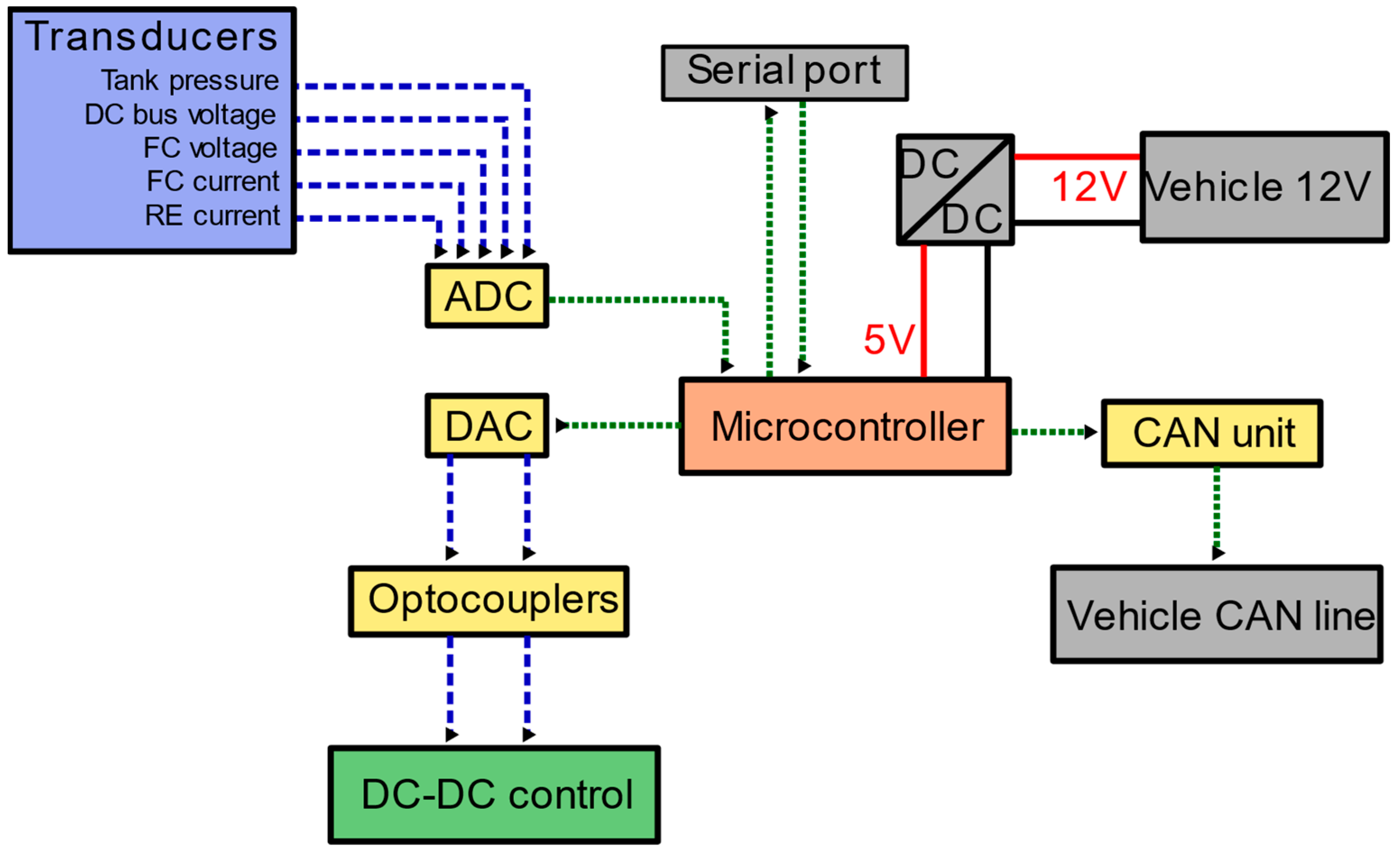
As for the range extender control unit, it was specifically designed for this application and consisted of a microcontroller, digital-to-analogue and analogue-to-digital converters (DAC and ADC), optocouplers, operational amplifiers (op-amps), and a CAN communication unit. A dual-channel DAC was used to generate the control signals to the DC-DC converter with a 12-bit resolution, while the optocouplers, specifically analogue optocouplers, were implemented to guarantee the separation between the grounds of the control and power stages. The op-amps were necessary for handling the signals. An eight-channel ADC was used to collect data from the transducers and convert those signals into high-resolution digital signals to be sent to the microcontroller. Lastly, a CAN communication unit, composed of a CAN controller and a CAN transceiver, was implemented to allow communication between the range extender unit and the on-board vehicle controller. The control unit was powered exploiting the 12V DC bus of the vehicle using an isolated DC-DC converter for generating a 5 V supply. A serial communication port was included to allow for the programming of the microcontroller from a personal computer and for data monitoring.
Figure 5 shows a simplified scheme of the control unit.
Figure 5.
Range extender control unit schematic layout. Please note that FC and RE mean fuel cell and range extender respectively.
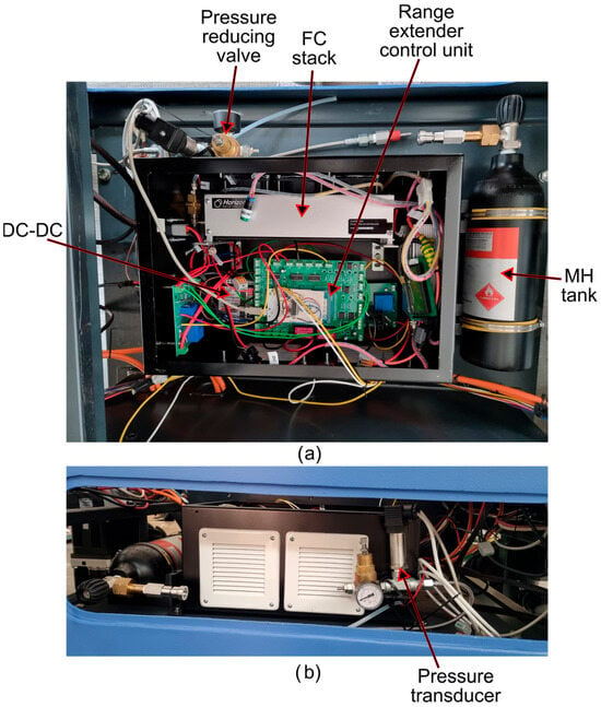
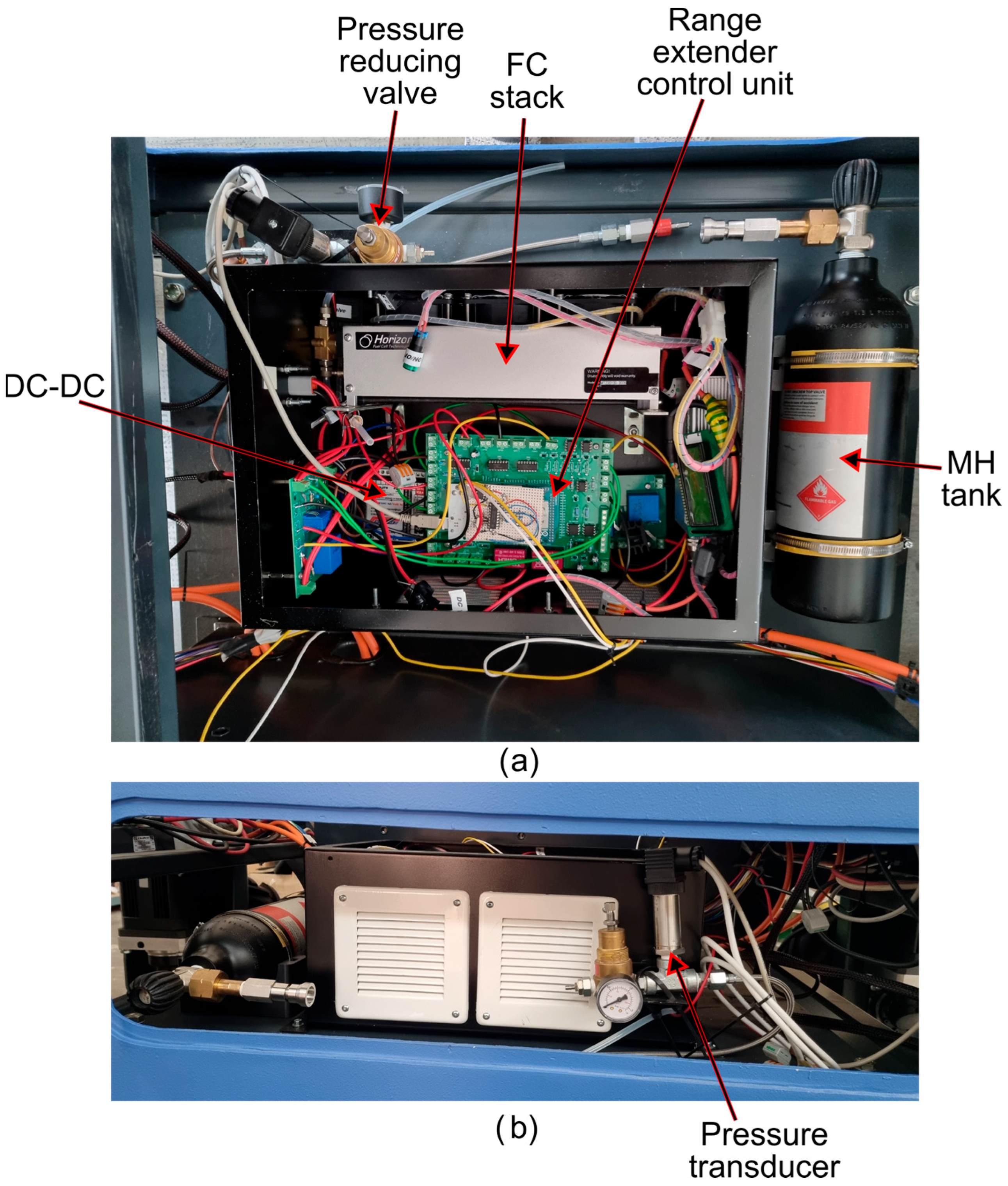
A photo of the range extender unit mounted on the rover’s chassis is shown in Figure 6. The unit mechanical layout comprised an external case, with ventilation grids, containing the electronic components, that was physically connected to the chassis using bolts and nuts. The tank was housed in a specific housing with a hemicylindrical shape and locked using metal clamps.
Figure 6.
Photos of the range extender unit mounted on Smilla H2; (a) top view, (b) side view.
2.3. Powertrain and Vehicle Control Strategy
Considering the whole vehicle, two different control strategy algorithms can be considered. The first one described the energy management of the hybrid propulsion system, thus defining the output of the range extender unit. The second one instead defined the torque command to be applied to the motors.
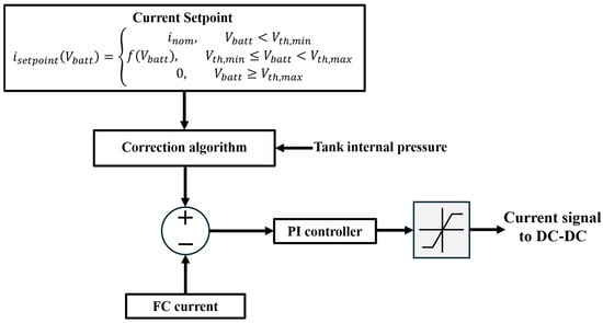
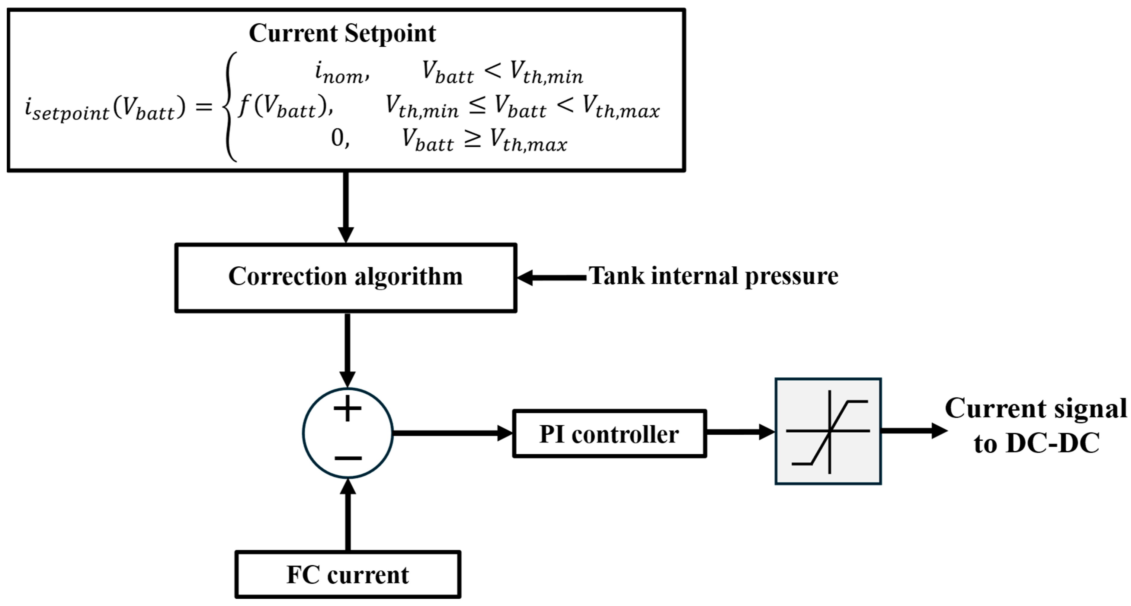
Starting with energy management, the DC-DC control was performed by generating a current reference signal and a voltage reference signal. The first element that was considered when defining the algorithm was the ratio between the rated power of the range extender and the overall motor power. This ratio was significantly low as the fuel cell rated power was 300 W, while the total motor power was 4800 W. Consequently, the energy management strategy was defined deeming that the power output of the fuel cell should not be dependent on the actual motor power, as it could not provide a significant contribution in satisfying peak power requests. This consideration indicated that a fixed-power output strategy was a feasible solution and oriented the authors towards that direction. This approach also allowed for preventing fast fuel cell aging, as a more stable output reduces degradation. To find the value of the power output, the authors considered both endurance extension and fuel cell aging. According to fuel cell aging models available in the literature, it can be noted that power fluctuations and high-power conditions can have a great effect on the expected durability [66,67]. On the other hand, the power output of the fuel cell should be high enough to effectively extend the rover’s endurance. According to all these considerations, the control strategy was defined considering a current setpoint reference value of 5 A, which corresponded to a stack power output around 220 W. A too low output would limit the endurance improvements as the unit would not provide enough power, while a too high power would reduce the expected lifetime of the fuel cell due to high-power conditions. Furthermore, increasing the power output is not necessary since peaks in power demands are handled by the battery pack. In normal conditions, the current control was predominant over the voltage control. This reference value was the current that the stack had to continuously deliver in normal conditions. However, to avoid overcharge of the battery pack, this setpoint was adjusted depending on the actual DC bus voltage, which was monitored using a dedicated voltage transducer as described in Section 2.2. Thus, the voltage control became predominant only in case of an almost fully charged BP. Lastly, the setpoint was reduced when the tank internal pressure reached a predefined lower threshold value to limit hydrogen consumption. Once the current setpoint was defined, a proportional–integrative (PI) controller was implemented to define the reference current signal to be sent to the DC-DC converter.
The control strategy is schematically represented in Figure 7. Please note that Vth,min was set equal to 54.4 V (corresponding to an average cell voltage of the battery pack equal to 3.45 V) and Vth,max equal to 56 V (3.5 V of BP average cell voltage). The function that described the current setpoint when the BP voltage was between those values was a linear function. The proposed approach was selected because of its very low computational effort, which allowed for easy and fast implementation in a real-time controller. Furthermore, for machines that must work several hours straight in harsh environments, robustness is another feature of particular interest. The proposed rule-based strategy with fixed power output can optimize the trade-off between efficiency, robustness and ease of implementation.
Figure 7.
Schematic representation of the fuel range extender energy management.
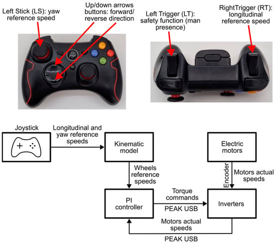
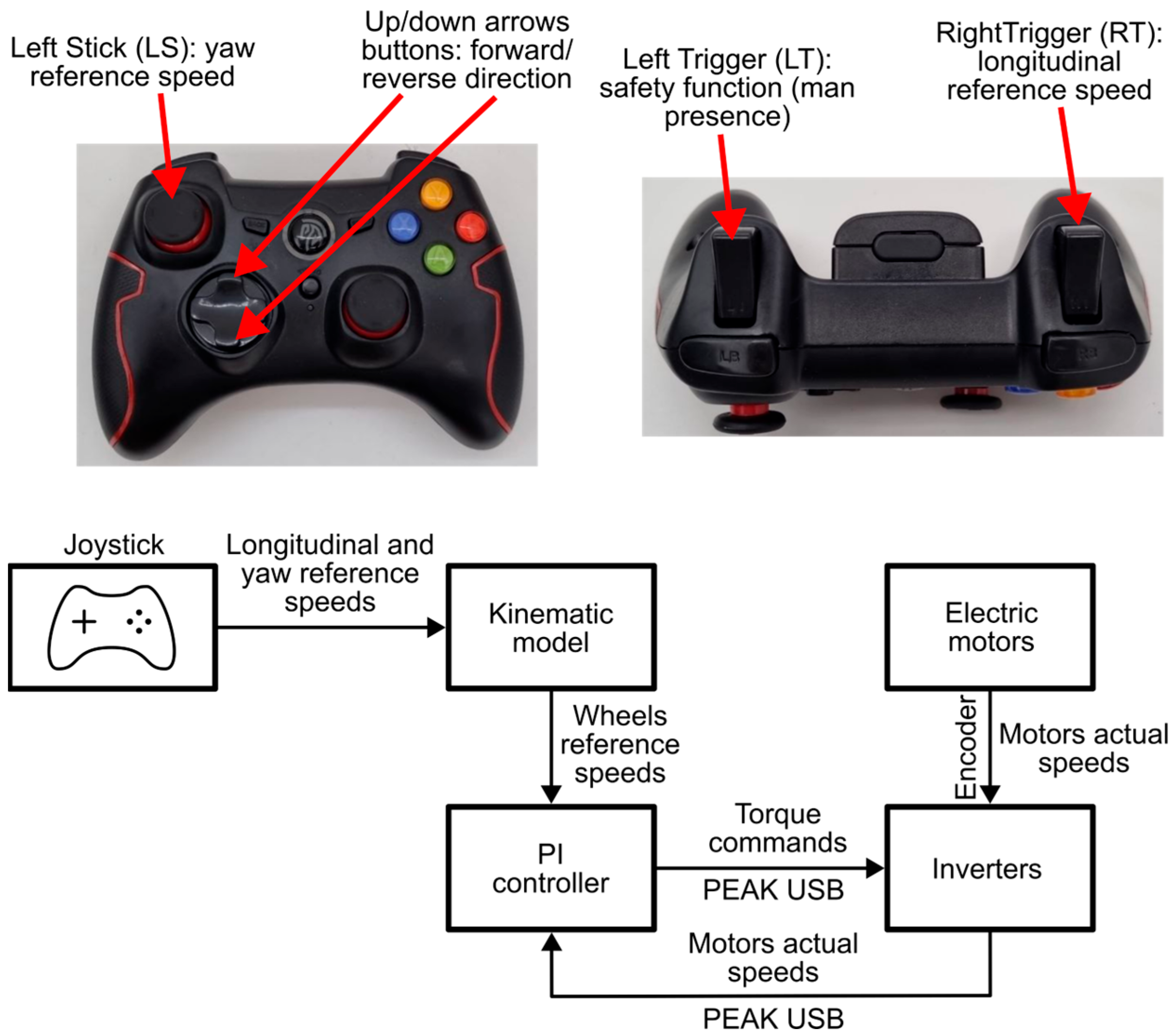
As for vehicle control, the rover was originally designed to operate using an autonomous driving algorithm. However, since the focus of the proposed research was to evaluate the behavior of the range extender unit, the authors opted to manually control the rover and perform different maneuvers in narrow spaces within a warehouse. To achieve this, an Xbox controller was exploited. Through this joystick, the driver had to indicate two main parameters: longitudinal and yaw speeds. This approach was coherent with the autonomous driving algorithm of the rover, which produces in output these two values [50,68]. The control algorithm was developed so that the right trigger button indicated the rover longitudinal speed, while the left stick indicated the yaw speed. In addition, the up and down arrow buttons were used to determine the forward/reverse direction. Lastly, the left trigger was used as a safety button ( human presence). The joystick was a wireless device that was connected to the on-board computer through a USB drive.
Once the longitudinal and yaw speeds were defined, the control algorithm evaluated the reference wheel speeds to obtain those values according to a torque vectoring technique. Next, the algorithm had to determine the torque commands to the motors based on the error between the actual and reference wheel speeds. To achieve this, another PI controller was implemented. In addition, the wheels’ actual speeds had to be known. The inverters adopted on the rover used CAN communication both to provide data and to be controlled. Consequently, a PCAN-USB device, manufactured by PEAK-System (PEAK-System Technik GmbH, Darmstadt, Germany), was used to allow CAN communication between the on-board computer and the inverters. Thus, the overall flow of the vehicle control was the following: through the joystick signals, the algorithm first determined the longitudinal and yaw speeds and evaluated, according to the rover’s geometry, the reference wheel speeds, next the actual motor speeds were collected from the inverters (thus the wheel speeds were known from the transmission ratio of the gear reducers), then it determined, according to the PI controller, the torque commands, and lastly it sent them to the inverters using the CAN protocol. The whole control software was developed as a python code (python 3.13).
A visual representation of the joystick and the vehicle control strategy is shown in Figure 8.
Figure 8.
Vehicle control algorithm.
2.4. Test Scenario
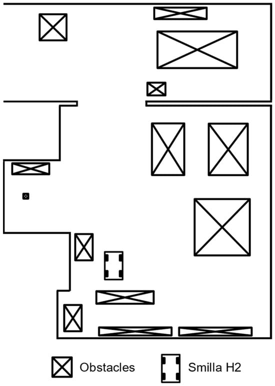
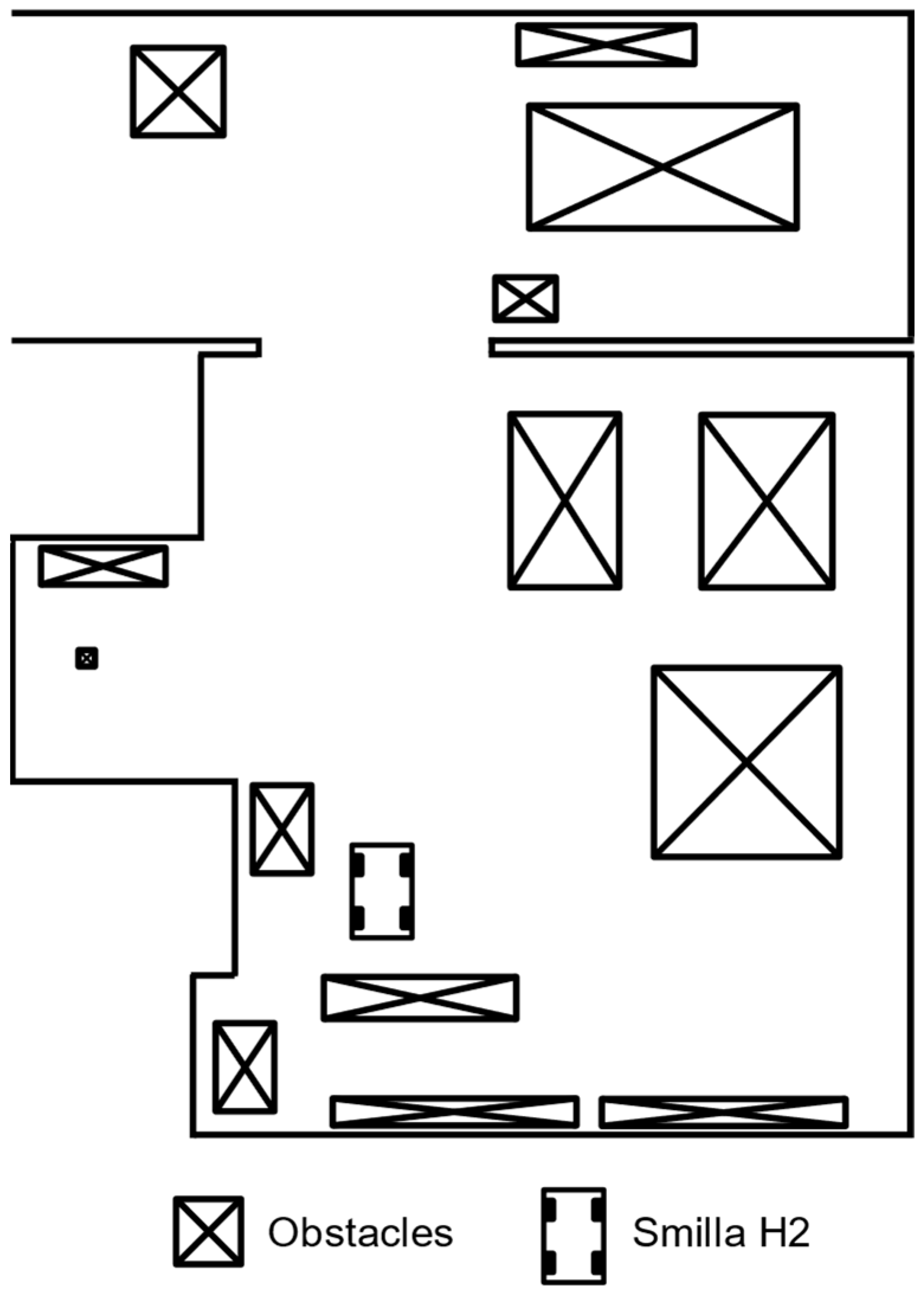
The experimental tests took place inside a warehouse with a polished concrete floor and were performed in collaboration with Ecothea. A floor plan of the testing area is shown in Figure 9.
Figure 9.
Floor plan of the testing area.
The area is characterized by the presence of several obstacles; thus, the rover had to perform maneuvers in very narrow spaces. This capability is a relevant requirement for this kind of vehicle due to the typical orchard configurations. During the experimental tests, the rover performed the following maneuvers:
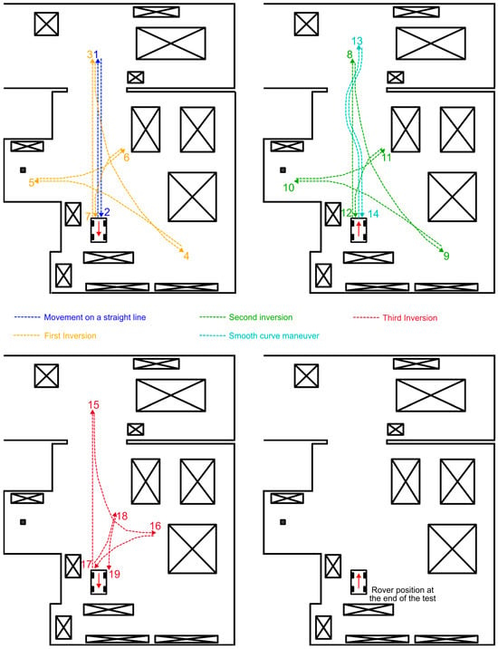
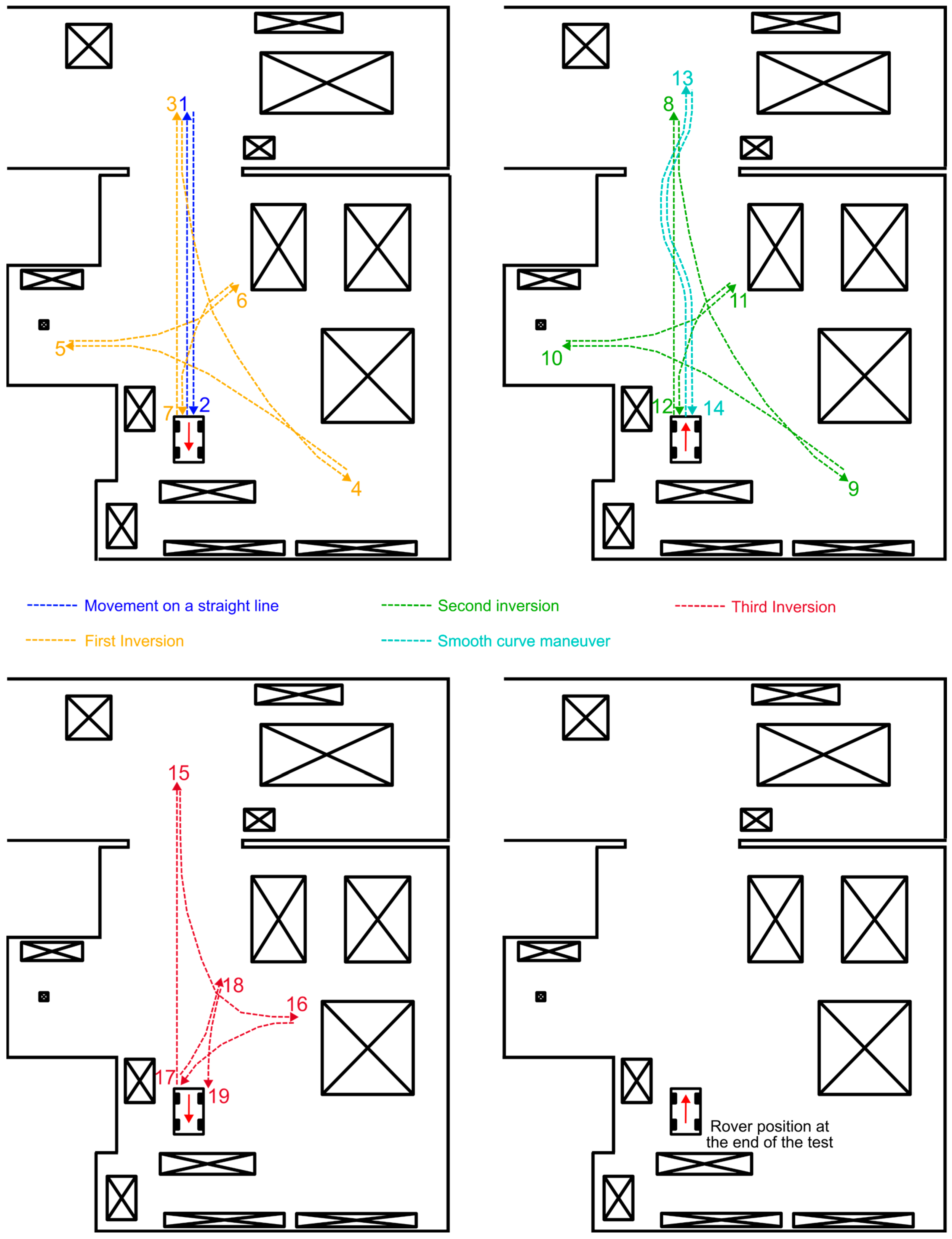
Movement in forward and backward directions on a straight line.
Slightly turn to one side and then to the other side (like an obstacle avoidance maneuver).
Inversion maneuvers.
To collect powertrain data during the experimental tests, a CAN analyzer device was adopted. In detail, a PCAN-GPS, manufactured by PEAK-System (PEAK-System Technik GmbH, Germany), was exploited. This device was connected to the CAN bus network of the vehicle and was programmed to save on an SD card the messages regarding the actual inverter and range extender unit operating conditions. In detail, the monitored parameters were actual motor speeds and currents, the actual fuel cell stack voltage and current, the range extender power output, and the tank internal pressure.
3. Results and Discussion
3.1. Experimental Test Results
As previously mentioned, during the experimental test the rover performed different maneuvers and was manually controlled using a joystick. The trajectories of the performed maneuvers are shown in Figure 10.
Figure 10.
Maneuvers performed during the experimental test. Please note that the numbers indicate the chronological order. The red arrow indicates the rover orientation at the beginning of the next maneuver according to the chronological order.
At the beginning of the test, the battery pack SoC was around 45% and the ambient temperature was equal to 25 °C.
The maneuvers were performed in sequence during a single test session, and their execution took approximately 15 min. At the end, the rover was left turned on for an additional five minutes to evaluate the behavior of the range extender unit when no external load was acting and after a work session. In addition, idle consumptions could be estimated.
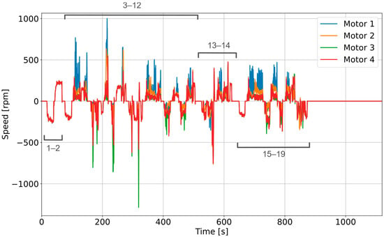
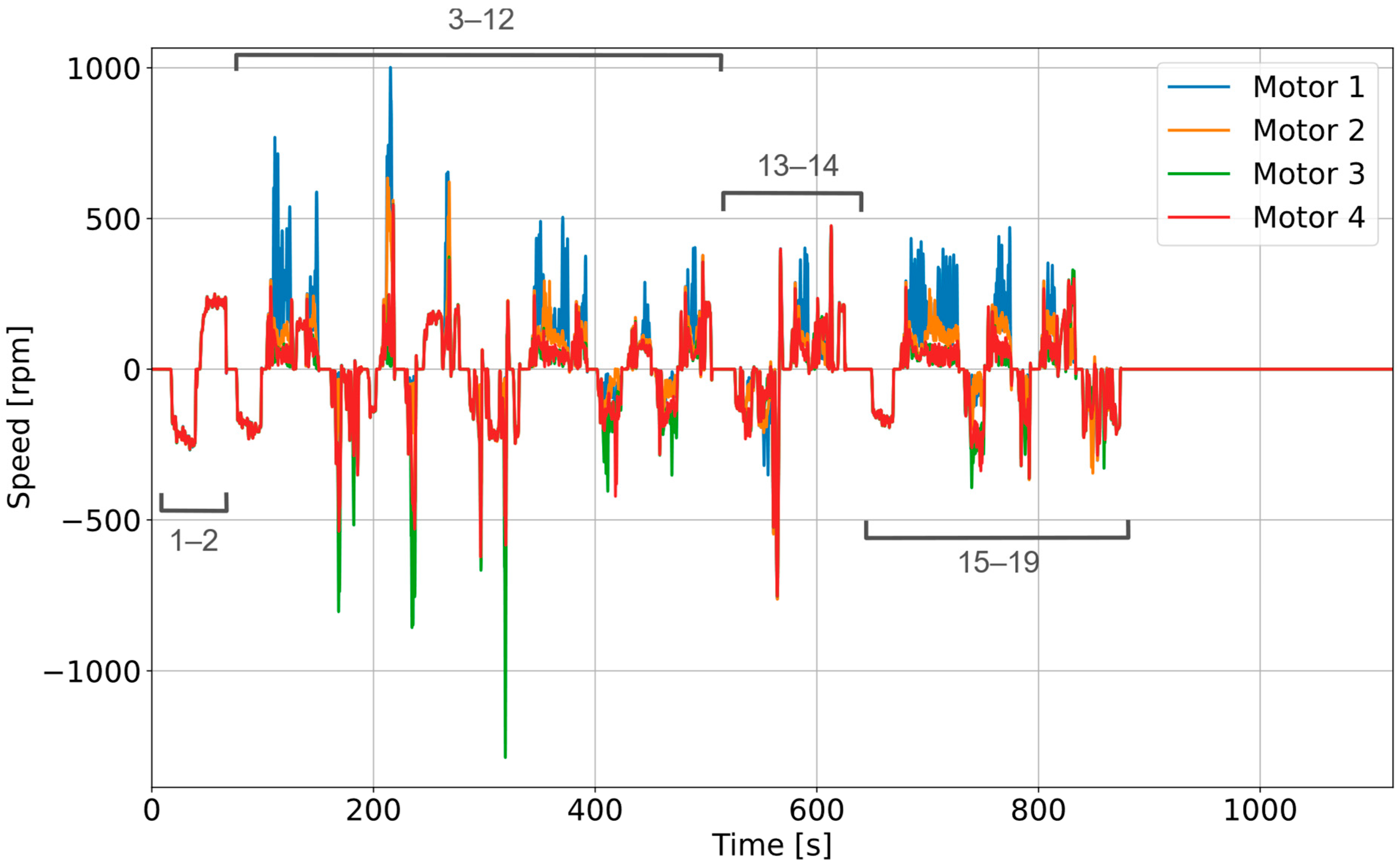
Figure 11 shows the motor speeds during the test. Analyzing the plot, it was observed that the rover was able to complete the maneuvers with sufficiently stable control. Indeed, the only points in which tire slip was significant were when the motor rotational speeds exceeded 800 rpm (in absolute value), which occurred for Motor 1 at 210 s and for Motor 3 at 220 and 310 s. The maximum absolute value of rotational speed recorded during the test was equal to approximately 1300 rpm.
Figure 11.
EM speeds during the experimental test. Please note that the numbers in grey indicate the corresponding maneuvers within the plot in accordance with Figure 10. Motor 1 refers to the front right motor, Motor 2 to the rear right motor, Motor 3 to the rear left and Motor 4 to the front left motor.
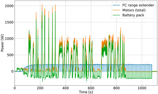
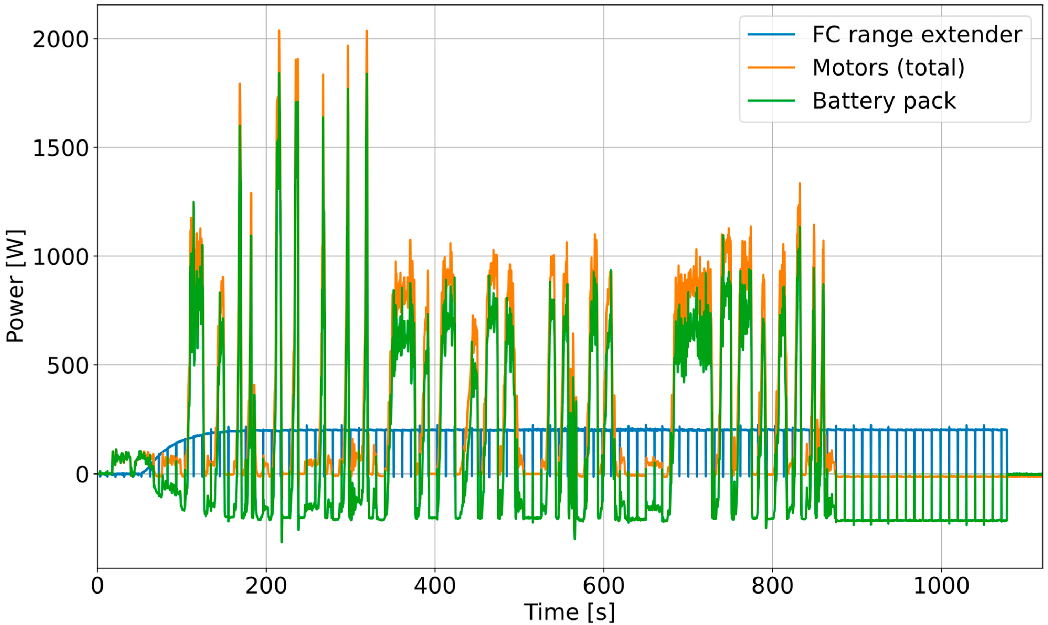
Figure 12 shows the power profiles of the motors, the range extender and the battery pack. As can be noted, the range extender unit followed the prescribed control strategy. After an initial start-up phase, in which the power output gradually increased from 0 to the predefined value of 220 W (approximately 5 A), it remained almost constant and was totally independent from the external load. In addition, the effects of the SCU are clearly visible as the output was brought to zero every 10 s. However, it did not have any impact on the control. Considering the power absorbed by the EMs, the maximum value was observed when performing a turn and was equal to slightly more than 2000 W. The maximum power delivered by the battery pack was equal to 1800 W and corresponded to a discharge current of approximately C/3.
Figure 12.
Total motors, range extender and battery pack power profiles during the experimental test.
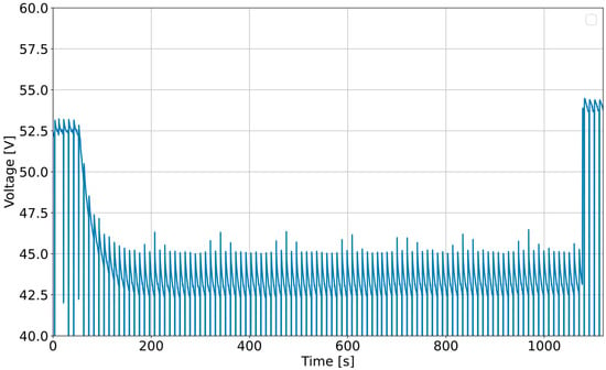
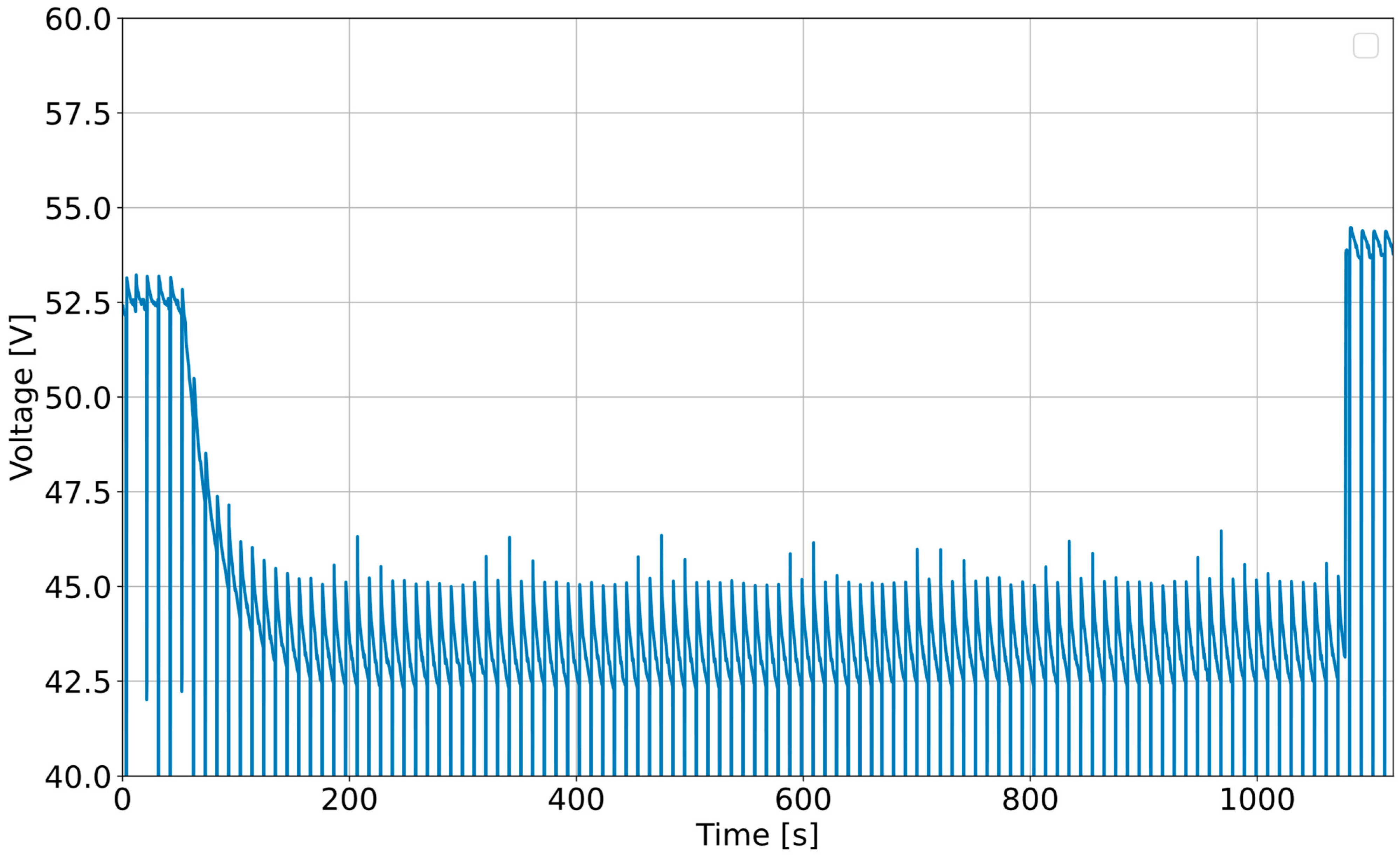
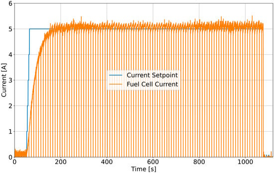
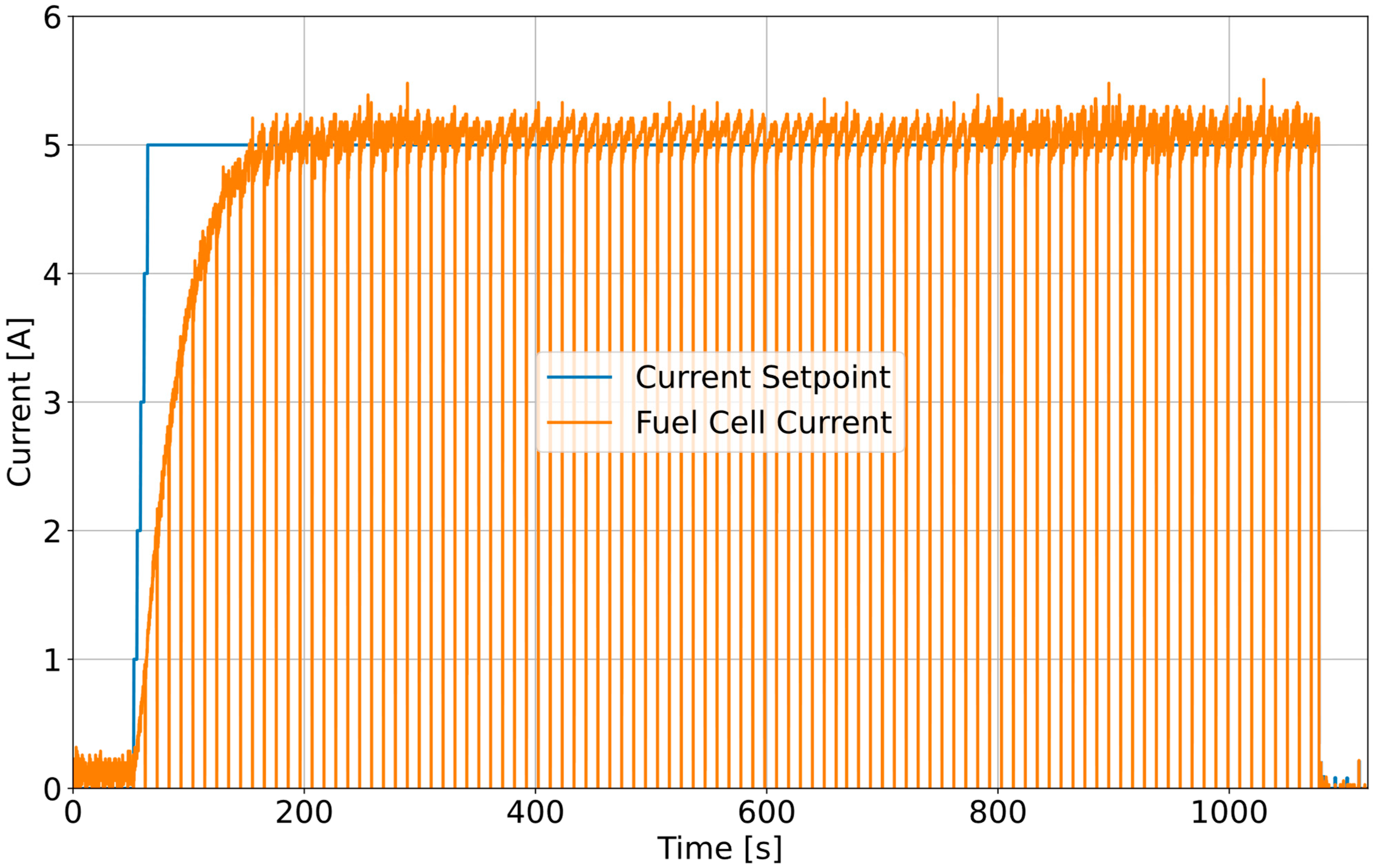
As for the fuel cell stack, its output voltage and current are reported in Figure 13 and Figure 14 respectively. Considering that the average value of the power output at the stack level was around 220 W, while downstream the DC-DC it was around 205 W, an efficiency of the DC-DC and the power circuits of 93–94% was estimated.
Figure 13.
Fuel cell stack output voltage during the test.
Figure 14.
Fuel cell stack current setpoint and actual output during the test.
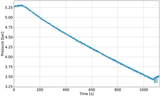
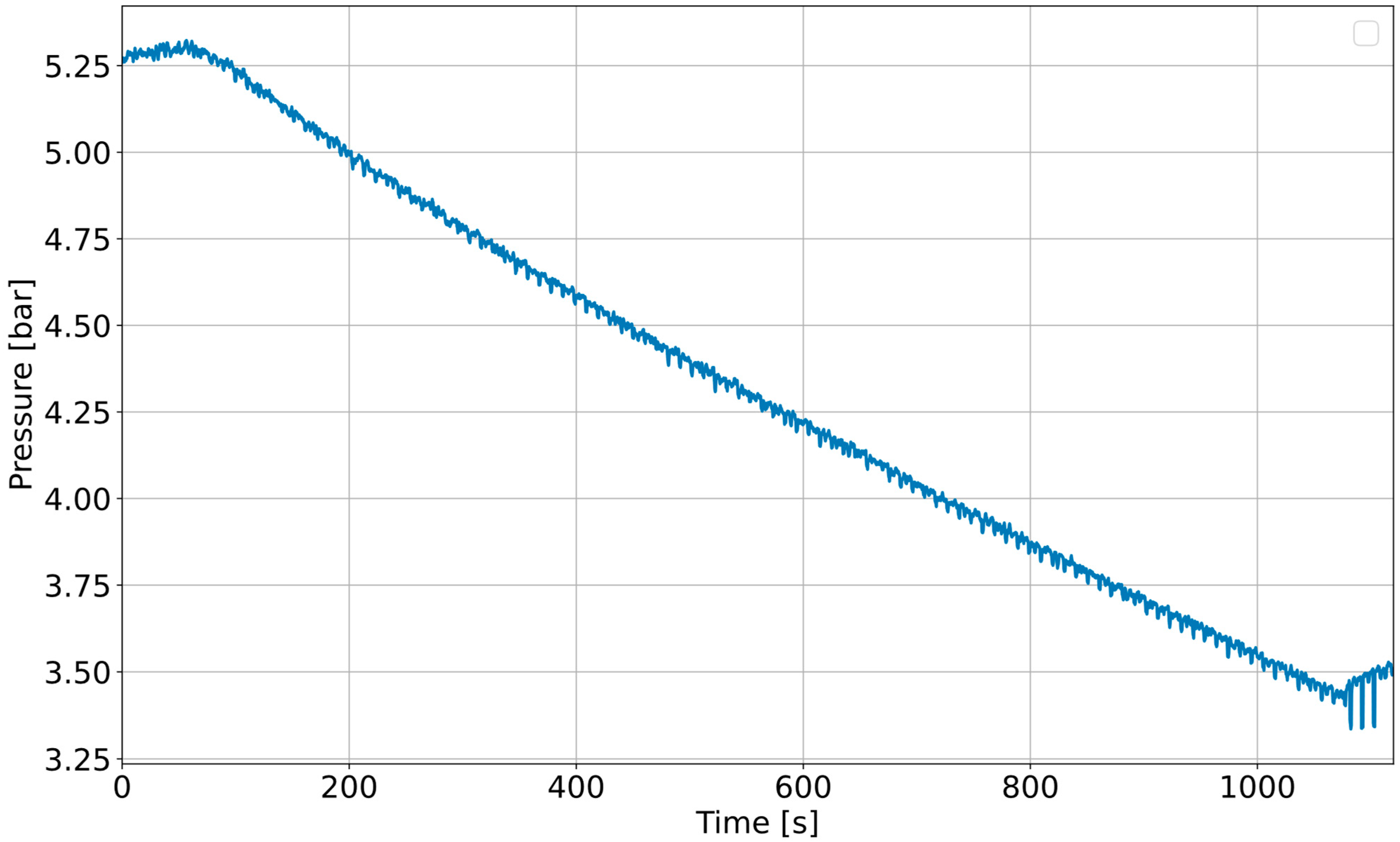
The MH tank internal pressure trend is illustrated in Figure 15. At the beginning of the test, the tank internal pressure was of 5.25 bar and decreased to 3.45 at the end.
Figure 15.
MH tank internal pressure during the test.
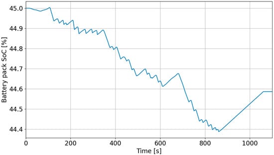
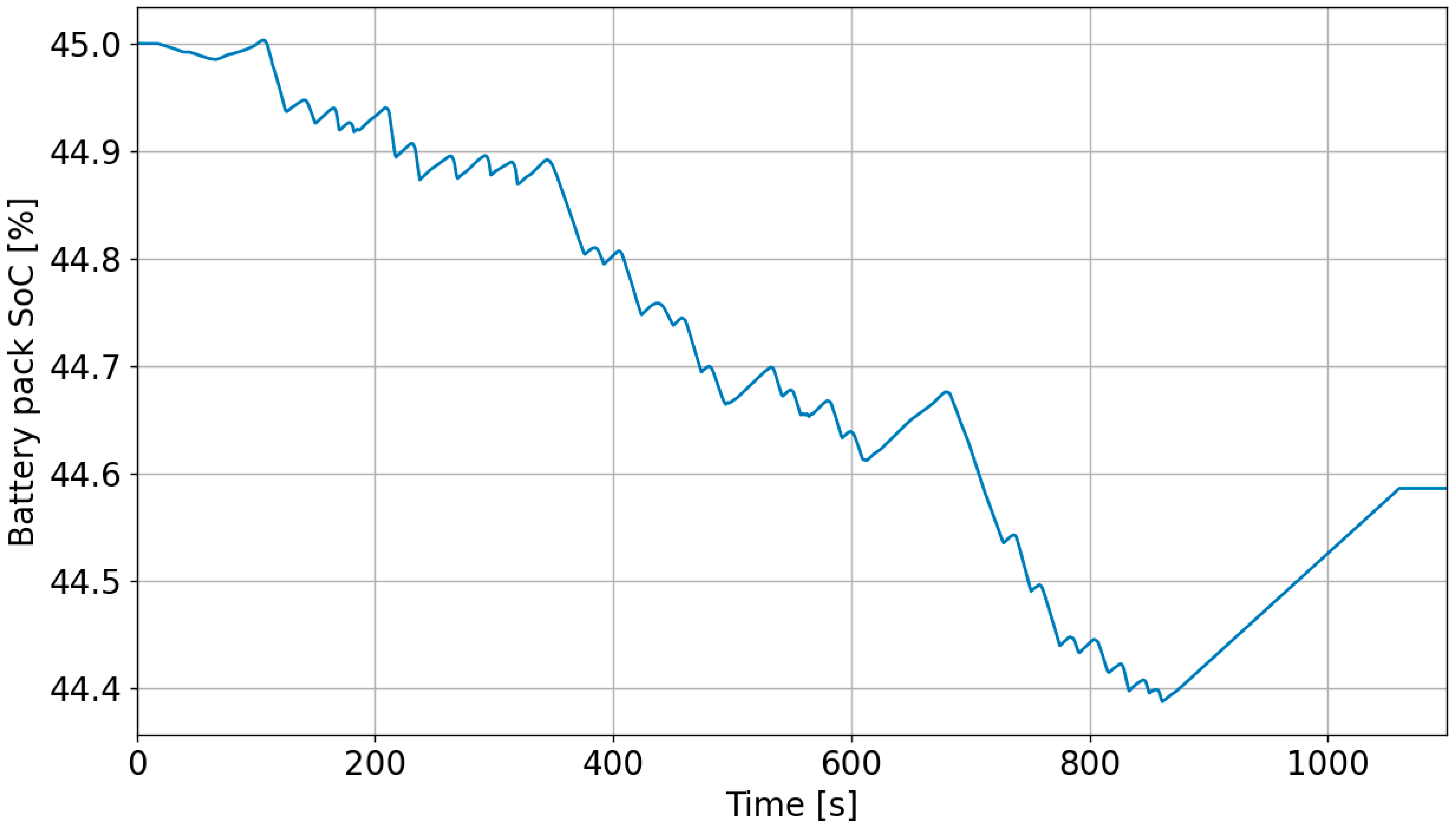
Lastly, Figure 16 shows the battery pack SoC trend during the test. Please note that, at the beginning of the test, the actual SoC was 45%.
Figure 16.
Battery Pack SoC in the test. Please note that, at the beginning of the test, the SoC was equal to 45%.
The main parameters monitored during the experimental test are summarized in Table 5.
Table 5.
Main parameters recorded during the experimental test. * The hydrogen consumption was estimated according to the stack fuel consumption curve provided by the manufacturer, no direct measurement on the hydrogen flow was performed.
3.2. Discussion
The results of the experimental test session highlighted several interesting aspects. First of all, the rover was able to complete different maneuvers in narrow spaces. This requirement is of primary importance when considering operations in orchards and vineyards. During tight turns, wheel slip was noted, along with a peak in the power absorption. This was caused by the adoption of the torque vectoring technique instead of a physical steering system. However, the rover was able to avoid excessive wheel slip and to recover traction to complete the maneuver.
As for the powertrain, the range extender unit behaved as expected and prescribed by the control strategy, maintaining a stable power output after reaching the regime condition. Furthermore, it was not dependent on the external load. Considering the whole experimental test, it was observed that the battery pack consumed energy equal to 23 Wh. Assuming that the cycle is repeated continuously, this would translate into 77 Wh consumed per hour, corresponding to an SoC consumption of 1.43%/h. This would indicate an endurance of 70 h straight. However, if the last part of the test, where the vehicle is not operating but the range extender unit is turned on, is not considered, the estimated endurance decreases to 40 h (2.5%/h). Since the MH tank can store up to 80 g of hydrogen and considering that the hydrogen consumed by FCS-C300 at 220 W of output power is equal to 3.05 × 10⁻³ g/s, after approximately 7 h and 17 min of operation the tank is fully discharged. Please note that hydrogen consumption is only estimated using the consumption curve provided by the manufacturer and no measurement system was used to monitor hydrogen flow. The manufacturer did not declare the error margin on the measurement; thus, no further details can be provided. At this point, the tank can be easily substituted by a fully charged one. In this way, excluding the downtime for the tank swap, the range extender unit can operate non-stop. Otherwise, the range extender unit has to be turned off until the tank is recharged.
To replace the tank, the following steps must be taken: first, the rover must be stopped by pressing the emergency push-button on the side of the chassis; then, the flatbed at the back of the rover must be opened. At this point, once the range extender control unit is turned off, the metal clamps must be loosened, the Swagelok quick connector unplugged and the tank removed. Once the new fully charged tank is inserted, the connector must be plugged in and metal clamps tightened. Then, the range extender unit can be turned on again. Finally, once the flatbed is closed, the rover can return to normal operation. The estimated stop time to perform this operation is 10 min and was estimated by performing the operation a few times and evaluating the mean recorded time. The procedure is very simple and can be easily performed in the field. Furthermore, thanks to its compactness, limited weight, and low internal pressure, the tank can be easily handled and carried. However, the estimated swap time is strictly related to the current disposition of the devices. In the case of future developments with a re-arrangement of the components’ positioning, the swap time may be significantly reduced.
If the range extender unit were not implemented, the expected endurance would have been 16 h (6.2%/h). Consequently, considering the work cycle derived from the experimental test, it can be stated that the range extender unit successfully improved the expected endurance of +150% considering substituting the tank when fully discharged. Otherwise, if the tank is not swapped with a charged one and the vehicle continues its operation until the BP is discharged, the expected endurance is approximately 20 h and 30 min. Consequently, the beneficial effects of the range extender unit are significantly improved if tank swapping is performed. However, it should be noted that with the adopted control strategy the rover is capable of operating for almost an entire workday (supposed of 8 h) with the range extender unit on, as the MH tank is discharged in more than 7 h. Indeed, at the end of the workday the tank can be recharged without requiring a tank swap if 8 h straight is considered as an operational requirement. Thus, summarizing the results, the hybrid powertrain can improve the endurance by +150% compared to the pure battery configuration if the tank is changed whenever it is fully discharged. If the tank cannot be swapped, with the battery pack fully charged the endurance is improved by +30% compared to the pure battery powertrain as the net electrical energy that can be produced by the fuel cell range extender unit corresponds to approximately 1.6 kWh, while the energy content of the BP is 5.4 kWh. If the initial SoC is different and a tank swap is not considered, the endurance improvements with the range extender will be higher. Indeed, in the case of an initial SoC equal to 50%, the net electrical energy produced by the range extender unit would be 60% of the energy stored in the battery pack. In the case of an initial SoC of 25%, it would be 118%.
Lastly, considering the internal pressure of the tank, it was noted that it decreased from 5.25 to 3.45 bar. This reduction is caused by both hydrogen consumption and temperature decrease. In detail, the effect of the temperature is predominant since hydrogen consumption in the plateau region has little effect on the internal pressure. The reduction in the tank temperature is caused by the hydrogen desorption process being endothermic. At the beginning of the test, the tank temperature was approximately 25 °C (298.15 K), while at the end it was around 15 °C (288.15 K). In addition, it was noted that the thermal regime was not reached. Consequently, as can be seen from the plot, the reduction rate was almost equal after 15 min. Nevertheless, once the regime is reached, the pressure will stabilize, ensuring the possibility to operate for enough time. However, to limit this behavior, which is particularly critical in the case of cold temperatures, dedicated measures should be taken.
A possible solution is to thermally couple the PEMFC system and the tank [69,70]. This approach uses forced convention, eventually exploiting the fans mounted on the stack, to transfer the heat produced by the fuel cell to the MH tank. A rough estimation derived by the tank characterization procedure is that the heat required by the tank during discharge is around 1/3 of the heat produced by the stack, thus if the stack and the tank are close to each other, the thermal coupling should not require additional components to be effectively obtained. Considering the current location and orientation of the components, it can be easily achieved by rotating the stack and the position of the ventilation grids by 90°, so that the fans are oriented facing the tank surface. To reduce waste heat, a bent sheet-metal panel can be installed behind the tank to prevent hot air from being dispersed behind it.
Despite the promising results, the proposed analysis has some limitations, mainly related to the experimental test session, that should be acknowledged. First of all, the test location was a warehouse with a polished concrete floor. The behavior of the rover in an orchard field, with very different soil conditions, might be significantly different. In addition, during the test the rover simply performed some maneuvers, however, it was designed to carry payloads and accomplish low-power tasks with specifically designed implements. Consequently, the power required for completing those tasks may be different from the one observed during the experimental test session. To address this issue, in-field tests with attached implements should be performed. To better understand the effects of these limitations on the reliability of the obtained results, a further discussion is presented in Section 3.3.
3.3. Main Limitations of the Proposed Study
A critical aspect of the proposed study is represented by the test location for the experimental testing of the Smilla H2 prototype. Indeed, the test was conducted in an indoor environment with a polished concrete floor, which is significantly different compared to an agricultural field. A major difference is related to the traction capability and to the power consumption on the different terrains. The polished concrete floor is characterized by lower friction and rolling resistance coefficients compared to a typical agricultural terrain, thus the overall power required for traction on an agricultural field is expected to be higher, while the maneuverability is expected to be lower. Moreover, in a real work scenario the motors will be continuously demanding power, while during the test performed the motor behavior is more intermittent. This is not a problem in terms of powertrain control strategy, but it can have an effect on the estimated endurance since the average power will be higher. According to estimations [50], the average power absorption due to the longitudinal movement of the rover considering a work speed of 3 km/h on typical agricultural terrains might be around 300–400 W. Furthermore, if the rover is using attached implements or carrying loads, the overall power consumption can be higher (600–700 W). According to this, the expected increase in rover endurance, compared to the pure battery solution, may be around +50/+60% considering a tank swap, with an expected working time of 10–11 h [58]. However, further tests are required since these are only estimations.
In addition, the effects of autonomous control cannot be determined as the rover was controlled using a joystick. Nevertheless, the traction control algorithm was the same in both cases, thus the traction performance and the rover endurance are not expected to significantly decrease when shifting from the manual control to the autonomous driving algorithm.
Another critical point is related to the MH tank internal pressure in the case of cold environments. The equilibrium pressure of the hydrogen desorption process is strictly related to the metal hydride temperature. Indeed, in the case of low environmental temperatures, the system might not be capable of using all the hydrogen stored in the tank due to excessive pressure reduction. The thermal coupling solution previously described in Section 3.2 can be a solution to mitigate the problem, however, in the case of very low temperatures further actions might be necessary, such as adopting a heat resistor to heat up the tank during the rover start-up phase. These aspects deserve more attention and might be the subject of future research activities.
Lastly, to provide statistical validation and enhance the reliability of the results, further experimental tests are required. Indeed, the test should be repeated a few times and in different conditions. A more extensive and consistent experimental campaign should be carried out to increase the amount of available data. In addition, a long-run test should be performed to evaluate the powertrain behavior over a more realistic test scenario.
4. Conclusions
In the proposed study, a hybrid propulsion system for an agricultural rover was designed and implemented on a prototype. The powertrain features four independent fixed wheels, each one connected to a dedicated 1.2 kW electric motor. The main on-board energy source is represented by a 5.4 kWh battery pack with Li-ion cells, while the fuel cell system, characterized by a nominal power of 300 W, acts as a range extender unit that operates to extend the rover endurance as much as possible. Hydrogen is stored on board using a metal hydride tank capable of storing up to 80 g of hydrogen and with a maximum operating pressure of 30 bar. The range extender unit was designed to avoid significant mechanical modifications to the existing rover layout, which was developed for the pure battery configuration.
Once the powertrain components were defined, both the vehicle and powertrain control strategies were defined. For the proposed analysis, the vehicle was manually controlled using a joystick. The range extender power output was defined using a rule-based algorithm according to which the output was maintained as stable as possible. Indeed, it was totally independent from the external load. The only derating factors were the DC bus voltage, to avoid overvoltage, and the tank internal pressure.
Next, an experimental test session within a warehouse was performed. During this session, the rover performed different maneuvers in narrow spaces. The data were collected by monitoring the CAN bus network of the rover using a dedicated CAN bus analyzer. Analyzing the data, the following results were obtained:
- On a smooth concrete floor with intermittent operation over a 1000 s test, the rover successfully performed the maneuvers, even if wheel slipping was noted during very tight turns.
- On a smooth concrete floor with intermittent operation over a 1000 s test, the powertrain operated according to the control strategy and the range extender unit was capable of improving the rover endurance by +150% compared to the full battery solution; this result was obtained considering tank swapping.
- On a smooth concrete floor with intermittent operation over a 1000 s test, the oscillations on the power output of the range extender unit, excluding the effects of the SCU, were very limited; according to fuel cell aging models available in the literature, this enhances the expected durability of the PEMFC system.
- In a closed environment and with intermittent operation over a 1000 s test, the tank internal pressure decreased as a consequence of its decrease in temperature due to the endothermic behavior of the hydrogen desorption process; this can be critical in very cold environmental conditions and may require additional measures.
Despite some limitations related to the test scenario, the promising results indicated that the adoption of fuel cells as range extender units can effectively improve agricultural rovers’ endurance. Furthermore, the adoption of a metal hydride tank can enhance compactness and introduce the possibility of a tank swap technique to allow continuous operation of the range extender.
Future works will focus on performing experimental tests in fields with attached implements to effectively evaluate the effectiveness of the range extender in real work conditions. Since the test location is the main limitation of the present study, future activities will prioritize this experimental activity. During these tests different terrain conditions might be tested, including loam, sandy, muddy and hard soils. To extend the analysis, different maneuvers and different payloads might also be considered. Lastly, different implements should also be used to characterize different field operations. Moreover, direct hydrogen flow measurement will be implemented to effectively evaluate the actual hydrogen consumption. Indeed, the approximation derived by the use of the consumption curve provided by the manufacturer is acceptable at this early stage of design and should be sufficiently accurate in case of stacks with a low level of degradation. In addition, the development of an optimized control strategy to achieve both endurance and fuel consumption minimization will be analyzed. Lastly, the environmental benefits of introducing autonomous driving rovers in orchards will be investigated according to a life cycle assessment approach.
Author Contributions
Conceptualization, V.M. and F.M.; methodology, V.M., M.S., S.M. and F.M.; software, V.M., M.S., S.M. and F.M.; validation, V.M., M.S., S.M. and F.M.; formal analysis, V.M.; investigation, V.M., M.S. and S.M.; resources, V.M., M.S. and A.S.; data curation, V.M. and F.M.; writing—original draft preparation, V.M.; writing—review and editing, V.M., M.S., S.M., F.M. and A.S.; visualization, V.M.; supervision, F.M.; project administration, F.M. and A.S.; funding acquisition, A.S. All authors have read and agreed to the published version of the manuscript.
Funding
This research received no external funding.
Data Availability Statement
The original contributions presented in the study are included in the article, further inquiries can be directed to the corresponding author.
Conflicts of Interest
The authors declare no conflicts of interest.
Abbreviations
The following abbreviations are used in this manuscript:
| ADC | Analogue-to-Digital converter |
| AUX | Auxiliaries |
| BMS | Battery Management System |
| BP | Battery Pack |
| CAN | Controlled Area Network |
| DAC | Digital-to-Analogue converter |
| DC | Direct Current |
| FC | Fuel Cell |
| LFP | Lithium Iron Phosphate |
| MH | Metal Hydride |
| PCT | Pressure vs. Concentration at given Temperature |
| PEMFC | Proton Exchange Membrane Fuel Cell |
| SCU | Short Circuit Unit |
| VCU | Vehicle Control Unit |
References
- Eom, J.; Hyun, M.; Lee, J.; Lee, H. Increase in Household Energy Consumption Due to Ambient Air Pollution. Nat. Energy 2020, 5, 976–984. [Google Scholar] [CrossRef] [Scilit]
- Taghizadeh-Hesary, F.; Taghizadeh-Hesary, F. The Impacts of Air Pollution on Health and Economy in Southeast Asia. Energies 2020, 13, 1812. [Google Scholar] [CrossRef] [Scilit]
- McDuffie, E.E.; Martin, R.V.; Spadaro, J.V.; Burnett, R.; Smith, S.J.; O’Rourke, P.; Hammer, M.S.; van Donkelaar, A.; Bindle, L.; Shah, V.; et al. Source Sector and Fuel Contributions to Ambient PM2.5 and Attributable Mortality across Multiple Spatial Scales. Nat. Commun. 2021, 12, 3594. [Google Scholar] [CrossRef] [Scilit]
- Stump, Á.; Szabó-Morvai, Á. The Effect of Air Pollution on Fertility in 657 European Regions. J. Environ. Econ. Manag. 2025, 130, 103111. [Google Scholar] [CrossRef] [Scilit]
- Ritchie, H.; Rosado, P.; Roser, M. Breakdown of Carbon Dioxide, Methane, and Nitrous Oxide Emissions by Sector. Our World in Data 2020. Available online: https://archive.ourworldindata.org/20260417-112857/emissions-by-sector.html (accessed on 31 March 2026).
- Calicioglu, O.; Flammini, A.; Bracco, S.; Bellù, L.; Sims, R. The Future Challenges of Food and Agriculture: An Integrated Analysis of Trends and Solutions. Sustainability 2019, 11, 222. [Google Scholar] [CrossRef] [Scilit]
- Yu, Z.; Yao, R.; Wu, H.; Wang, Z. Green Finance and Agricultural Carbon Emissions. Financ. Res. Lett. 2025, 86, 108698. [Google Scholar] [CrossRef] [Scilit]
- Feng, T.; Liu, B.; Hu, C.; Wang, Z.; Liu, T.; Zhou, Z. Research on Sustainable Agricultural Resource Management Considering the Potential of Carbon Emission Reduction. Sustain. Energy Technol. Assess. 2025, 83, 104641. [Google Scholar] [CrossRef] [Scilit]
- Bacenetti, J.; Lovarelli, D.; Facchinetti, D.; Pessina, D. An Environmental Comparison of Techniques to Reduce Pollutants Emissions Related to Agricultural Tractors. Biosyst. Eng. 2018, 171, 30–40. [Google Scholar] [CrossRef] [Scilit]
- Tomić, M.; Savin, L.; Simikić, M.; Kiss, F.; Kešelj, K.; Ivanišević, M.; Ponjičan, O.; Zoranović, M.; Sedlar, A. Effects of Biodiesel on Changes in IC Engine Performances: A Long-Term Experiment with Farm Tractors. Fuel 2021, 292, 120300. [Google Scholar] [CrossRef] [Scilit]
- Owczuk, M.; Matuszewska, A.; Kruczyński, S.; Kamela, W. Evaluation of Using Biogas to Supply the Dual Fuel Diesel Engine of an Agricultural Tractor. Energies 2019, 12, 1071. [Google Scholar] [CrossRef] [Scilit]
- Kuranc, A.; Bawej, S.; Słowik, T.; Šarkan, B.; Dudziak, A.; Zając, G.; Paciolla, F.; Pascuzzi, S.; Łyp-Wrońska, K. Experimental Assessment of Energy-Ecological Parameters of Biogas-Powered Tractor Within Circular Economy. Energies 2024, 18, 7. [Google Scholar] [CrossRef] [Scilit]
- Simikic, M.; Tomic, M.; Savin, L.; Micic, R.; Ivanisevic, I.; Ivanisevic, M. Influence of Biodiesel on the Performances of Farm Tractors: Experimental Testing in Stationary and Non-Stationary Conditions. Renew. Energy 2018, 121, 677–687. [Google Scholar] [CrossRef] [Scilit]
- Mocera, F.; Somà, A.; Martelli, S.; Martini, V. Trends and Future Perspective of Electrification in Agricultural Tractor-Implement Applications. Energies 2023, 16, 6601. [Google Scholar] [CrossRef] [Scilit]
- Bortolini, M.; Cascini, A.; Gamberi, M.; Mora, C.; Regattieri, A. Sustainable Design and Life Cycle Assessment of an Innovative Multi-Functional Haymaking Agricultural Machinery. J. Clean. Prod. 2014, 82, 23–36. [Google Scholar] [CrossRef] [Scilit]
- Xu, L.; Hou, S.; Li, Y.; Lei, S.; Liu, M. Optimization Design and Experimental Verification of the Hydrogen-Powered Self-Propelled Plant Protection Machine. Energies 2025, 18, 4952. [Google Scholar] [CrossRef] [Scilit]
- Moreda, G.P.; Muñoz-García, M.A.; Barreiro, P. High Voltage Electrification of Tractor and Agricultural Machinery—A Review. Energy Convers. Manag. 2016, 115, 117–131. [Google Scholar] [CrossRef] [Scilit]
- Martini, V.; Mocera, F.; Somà, A. Carbon Footprint Enhancement of an Agricultural Telehandler through the Application of a Fuel Cell Powertrain. World Electr. Veh. J. 2024, 15, 91. [Google Scholar] [CrossRef] [Scilit]
- Martelli, S.; Martini, V.; Mocera, F.; Soma’, A. Life Cycle Assessment Comparison of Orchard Tractors Powered by Diesel and Hydrogen Fuel Cell. Energies 2024, 17, 4599. [Google Scholar] [CrossRef] [Scilit]
- Lajunen, A.; Kivekäs, K.; Freyermuth, V.; Vijayagopal, R.; Kim, N. Simulation-Based Assessment of Energy Consumption of Alternative Powertrains in Agricultural Tractors. World Electr. Veh. J. 2024, 15, 86. [Google Scholar] [CrossRef] [Scilit]
- Pascuzzi, S.; Łyp-Wrońska, K.; Gdowska, K.; Paciolla, F. Sustainability Evaluation of Hybrid Agriculture-Tractor Powertrains. Sustainability 2024, 16, 1184. [Google Scholar] [CrossRef] [Scilit]
- Martelli, S.; Mocera, F.; Somà, A. Co-Simulation of a Specialized Tractor for Autonomous Driving in Orchards. In Proceedings of the Conference on Sustainable Mobility, Catania, Italy, 25 September 2022. [Google Scholar]
- Sok, J.; Hoestra, J. Will Farmers Go Electric? How Dutch Environmental Regulation Affects Tractor Purchase Motivations and Preferences. Energy Res. Soc. Sci. 2023, 102, 103180. [Google Scholar] [CrossRef] [Scilit]
- Mocera, F.; Martini, V.; Somà, A. Comparative Analysis of Hybrid Electric Architectures for Specialized Agricultural Tractors. Energies 2022, 15, 1944. [Google Scholar] [CrossRef] [Scilit]
- Pesonen, J.; Prinz, R.; Ovaskainen, H.; Kauranen, P.; Poikela, A.; Kärhä, K. Alternative Powertrains and Fuels in Heavy Non-Road Mobile Machinery and Their Future Expectations—A Review. Curr. For. Rep. 2025, 11, 10. [Google Scholar] [CrossRef] [Scilit]
- Martini, V.; Mocera, F.; Somà, A. Numerical Investigation of a Fuel Cell-Powered Agricultural Tractor. Energies 2022, 15, 8818. [Google Scholar] [CrossRef] [Scilit]
- Martini, V.; Mocera, F.; Somà, A. Comparative Analysis of Hybrid Fuel Cell Powertrain Architectures for Orchard Tractors Using Hardware-in-the-Loop Technique. Energy 2025, 340, 139331. [Google Scholar] [CrossRef] [Scilit]
- Kivekäs, K.; Lajunen, A. Energy Efficiency and Carbon Dioxide Emissions of Agricultural Tractors Using Different Powertrains. Energy Rep. 2025, 14, 2755–2767. [Google Scholar] [CrossRef] [Scilit]
- Ji, M.; Wang, J. Review and Comparison of Various Hydrogen Production Methods Based on Costs and Life Cycle Impact Assessment Indicators. Int. J. Hydrog. Energy 2021, 46, 38612–38635. [Google Scholar] [CrossRef] [Scilit]
- Cho, H.H.; Strezov, V.; Evans, T.J. Environmental Impact Assessment of Hydrogen Production via Steam Methane Reforming Based on Emissions Data. Energy Rep. 2022, 8, 13585–13595. [Google Scholar] [CrossRef] [Scilit]
- Louli, R.; Giurgea, S.; Salhi, I.; Laghrouche, S.; Djerdir, A. A Critical Review of Green Hydrogen Production by Electrolysis: From Technology and Modeling to Performance and Cost. Energies 2025, 19, 59. [Google Scholar] [CrossRef] [Scilit]
- Ishaq, H.; Crawford, C. Towards Less Carbon-Intensive Blue Hydrogen: Integrated Natural Gas Reforming and CO2 Capture Approach. J. Environ. Chem. Eng. 2025, 13, 115043. [Google Scholar] [CrossRef] [Scilit]
- IEA. IEA Global Hydrogen Review; IEA: Paris, France, 2025. [Google Scholar]
- Moon, S.; Lee, Y.-J.; Lee, D.-J. A Cost-Effectiveness Analysis of Fuel Cell Electric Vehicles Considering Infrastructure Costs and Greenhouse Gas Emissions: An Empirical Case Study in Korea. Sustain. Energy Technol. Assess. 2022, 54, 102777. [Google Scholar] [CrossRef] [Scilit]
- Nguyen, H.L.; Han, J.; Nguyen, X.L.; Yu, S.; Goo, Y.-M.; Le, D.D. Review of the Durability of Polymer Electrolyte Membrane Fuel Cell in Long-Term Operation: Main Influencing Parameters and Testing Protocols. Energies 2021, 14, 4048. [Google Scholar] [CrossRef] [Scilit]
- Olabi, A.G.; Abdelkareem, M.A.; Wilberforce, T.; Alami, A.H.; Alkhalidi, A.; Hassan, M.M.; Sayed, E.T. Strength, Weakness, Opportunities, and Threats (SWOT) Analysis of Fuel Cells in Electric Vehicles. Int. J. Hydrog. Energy 2023, 48, 23185–23211. [Google Scholar] [CrossRef] [Scilit]
- Trencher, G.; Wesseling, J. Roadblocks to Fuel-Cell Electric Vehicle Diffusion: Evidence from Germany, Japan and California. Transp. Res. Part D Transp. Environ. 2022, 112, 103458. [Google Scholar] [CrossRef] [Scilit]
- Liu, L.; Yang, F.; Liu, X.; Du, Y.; Li, X.; Li, G.; Chen, D.; Zhu, Z.; Song, Z. A Review of the Current Status and Common Key Technologies for Agricultural Field Robots. Comput. Electron. Agric. 2024, 227, 109630. [Google Scholar] [CrossRef] [Scilit]
- Fountas, S.; Mylonas, N.; Malounas, I.; Rodias, E.; Hellmann Santos, C.; Pekkeriet, E. Agricultural Robotics for Field Operations. Sensors 2020, 20, 2672. [Google Scholar] [CrossRef] [Scilit]
- Martos, V.; Ahmad, A.; Cartujo, P.; Ordoñez, J. Ensuring Agricultural Sustainability through Remote Sensing in the Era of Agriculture 5.0. Appl. Sci. 2021, 11, 5911. [Google Scholar] [CrossRef] [Scilit]
- Linaza, M.T.; Posada, J.; Bund, J.; Eisert, P.; Quartulli, M.; Döllner, J.; Pagani, A.; Olaizola, I.G.; Barriguinha, A.; Moysiadis, T.; et al. Data-Driven Artificial Intelligence Applications for Sustainable Precision Agriculture. Agronomy 2021, 11, 1227. [Google Scholar] [CrossRef] [Scilit]
- MarketsandMarkets Agricultural Robots Market by Robot Type (Unmanned Aerial Vehicles, Milking Robots), Application (Harvest Management, Dairy & Livestock Management), Offering (Hardware, Software), End Use, Farming Environment, Farm Size, and Region—Global Forecast to 2030. Available online: https://www.marketsandmarkets.com/Market-Reports/agricultural-robot-market-173601759.html (accessed on 9 November 2025).
- Fontani, M.; Luglio, S.M.; Gagliardi, L.; Peruzzi, A.; Frasconi, C.; Raffaelli, M.; Fontanelli, M. A Systematic Review of 59 Field Robots for Agricultural Tasks: Applications, Trends, and Future Directions. Agronomy 2025, 15, 2185. [Google Scholar] [CrossRef] [Scilit]
- AgXeed AgBots. Available online: https://www.agxeed.com/solutions/agbots/ (accessed on 9 November 2025).
- Aigen Robotics. AI Generated Agriculture. Available online: https://www.aigen.io/ (accessed on 9 November 2025).
- Mustafa, R.J.; Gomaa, M.R.; Al-Dhaifallah, M.; Rezk, H. Environmental Impacts on the Performance of Solar Photovoltaic Systems. Sustainability 2020, 12, 608. [Google Scholar] [CrossRef] [Scilit]
- Ghobadpour, A.; Cardenas, A.; Monsalve, G.; Mousazadeh, H. Optimal Design of Energy Sources for a Photovoltaic/Fuel Cell Extended-Range Agricultural Mobile Robot. Robotics 2023, 12, 13. [Google Scholar] [CrossRef] [Scilit]
- Gonzalez-de-Soto, M.; Emmi, L.; Benavides, C.; Garcia, I.; Gonzalez-de-Santos, P. Reducing Air Pollution with Hybrid-Powered Robotic Tractors for Precision Agriculture. Biosyst. Eng. 2016, 143, 79–94. [Google Scholar] [CrossRef] [Scilit]
- Ecothea Srl Smilla H2. Available online: https://ecothea.it/attivita-e-progetti/smilla-h2/ (accessed on 5 May 2025).
- Martelli, S.; Martini, V.; Mocera, F.; Soma’, A. Co-Simulation Model of an Autonomous Driving Rover for Agricultural Applications. Robotics 2025, 14, 120. [Google Scholar] [CrossRef] [Scilit]
- Li, Y.; Teliz, E.; Zinola, F.; Díaz, V. Design of a AB5-Metal Hydride Cylindrical Tank for Hydrogen Storage. Int. J. Hydrog. Energy 2021, 46, 33889–33898. [Google Scholar] [CrossRef] [Scilit]
- Scarpati, G.; Frasci, E.; Di Ilio, G.; Jannelli, E. A Comprehensive Review on Metal Hydrides-Based Hydrogen Storage Systems for Mobile Applications. J. Energy Storage 2024, 102, 113934. [Google Scholar] [CrossRef] [Scilit]
- Somà, A. Unmanned Agricultural Rover Having a Fuel Cell Propulsion. Available online: https://patents.google.com/patent/WO2026013619A2/en (accessed on 31 March 2026).
- Das, H.S.; Tan, C.W.; Yatim, A.H.M. Fuel Cell Hybrid Electric Vehicles: A Review on Power Conditioning Units and Topologies. Renew. Sustain. Energy Rev. 2017, 76, 268–291. [Google Scholar] [CrossRef] [Scilit]
- Danebergs, J.; Deledda, S. Can Hydrogen Storage in Metal Hydrides Be Economically Competitive with Compressed and Liquid Hydrogen Storage? A Techno-Economical Perspective for the Maritime Sector. Int. J. Hydrog. Energy 2024, 50, 1040–1054. [Google Scholar] [CrossRef] [Scilit]
- Franco, A.; Giovannini, C. Hydrogen Gas Compression for Efficient Storage: Balancing Energy and Increasing Density. Hydrogen 2024, 5, 293–311. [Google Scholar] [CrossRef] [Scilit]
- Voss, W. A Comprehensible Guide to Controller Area Network; Copperhill Technologies Corporation: Greenfield, MA, USA, 2005. [Google Scholar]
- Martini, V.; Martelli, S.; Mocera, F.; Somà, A. Experimental Characterization and Co-Simulation Analysis of an Agricultural Rover with a Fuel-Cell Range-Extender Unit. Energies 2025, 18, 6432. [Google Scholar] [CrossRef] [Scilit]
- Dudek, M.; Zarzycki, M.; Raźniak, A.; Rosół, M. Applying a 2 KW Polymer Membrane Fuel-Cell Stack to Building Hybrid Power Sources for Unmanned Ground Vehicles. Energies 2023, 16, 7531. [Google Scholar] [CrossRef] [Scilit]
- Zhang, C.; Liu, H.; Zeng, T.; Chen, J.; Lin, P.; Deng, B.; Liu, F.; Zheng, Y. Systematic Study of Short Circuit Activation on the Performance of PEM Fuel Cell. Int. J. Hydrog. Energy 2021, 46, 23489–23497. [Google Scholar] [CrossRef] [Scilit]
- Afzal, M.; Mane, R.; Sharma, P. Heat Transfer Techniques in Metal Hydride Hydrogen Storage: A Review. Int. J. Hydrog. Energy 2017, 42, 30661–30682. [Google Scholar] [CrossRef] [Scilit]
- Suárez, S.H.; Chabane, D.; N’Diaye, A.; Ait-Amirat, Y.; Djerdir, A. Static and Dynamic Characterization of Metal Hydride Tanks for Energy Management Applications. Renew. Energy 2022, 191, 59–70. [Google Scholar] [CrossRef] [Scilit]
- Bellosta von Colbe, J.; Ares, J.-R.; Barale, J.; Baricco, M.; Buckley, C.; Capurso, G.; Gallandat, N.; Grant, D.M.; Guzik, M.N.; Jacob, I.; et al. Application of Hydrides in Hydrogen Storage and Compression: Achievements, Outlook and Perspectives. Int. J. Hydrog. Energy 2019, 44, 7780–7808. [Google Scholar] [CrossRef] [Scilit]
- Klopčič, N.; Grimmer, I.; Winkler, F.; Sartory, M.; Trattner, A. A Review on Metal Hydride Materials for Hydrogen Storage. J. Energy Storage 2023, 72, 108456. [Google Scholar] [CrossRef] [Scilit]
- Chen, H.; Zhao, X.; Zhang, T.; Pei, P. The Reactant Starvation of the Proton Exchange Membrane Fuel Cells for Vehicular Applications: A Review. Energy Convers. Manag. 2019, 182, 282–298. [Google Scholar] [CrossRef] [Scilit]
- Pei, P.; Chang, Q.; Tang, T. A Quick Evaluating Method for Automotive Fuel Cell Lifetime. Int. J. Hydrog. Energy 2008, 33, 3829–3836. [Google Scholar] [CrossRef] [Scilit]
- Jia, C.; Zhou, J.; He, H.; Li, J.; Wei, Z.; Li, K.; Shi, M. A Novel Energy Management Strategy for Hybrid Electric Bus with Fuel Cell Health and Battery Thermal- and Health-Constrained Awareness. Energy 2023, 271, 127105. [Google Scholar] [CrossRef] [Scilit]
- Martelli, S.; Mocera, F.; Somà, A. Autonomous Driving Strategy for a Specialized Four-Wheel Differential-Drive Agricultural Rover. AgriEngineering 2024, 6, 1937–1958. [Google Scholar] [CrossRef] [Scilit]
- Omrani, R.; Nguyen, H.Q.; Shabani, B. Thermal Coupling of an Open-Cathode Proton Exchange Membrane Fuel Cell with Metal Hydride Canisters: An Experimental Study. Int. J. Hydrog. Energy 2020, 45, 28940–28950. [Google Scholar] [CrossRef] [Scilit]
- Cetinkaya, S.A.; Disli, T.; Soyturk, G.; Kizilkan, O.; Colpan, C.O. A Review on Thermal Coupling of Metal Hydride Storage Tanks with Fuel Cells and Electrolyzers. Energies 2023, 16, 341. [Google Scholar] [CrossRef] [Scilit]

Disclaimer/Publisher’s Note: The statements, opinions and data contained in all publications are solely those of the individual author(s) and contributor(s) and not of MDPI and/or the editor(s). MDPI and/or the editor(s) disclaim responsibility for any injury to people or property resulting from any ideas, methods, instructions or products referred to in the content. |
© 2026 by the authors. Licensee MDPI, Basel, Switzerland. This article is an open access article distributed under the terms and conditions of the Creative Commons Attribution (CC BY) license.