


Abstract
Conventional osteosynthesis plates provide reliable fixation for bone fractures, but their design is predominantly functional and rarely addresses the patient’s emotional or symbolic relationship with the implanted device. This study introduces Biofiligree®, a design-led fixation concept inspired by traditional Portuguese filigree, in which osteosynthesis plates are conceived simultaneously as biomedical implants and personalised artefacts that may later be transformed into wearable jewellery after fracture healing and plate removal. A proof-of-concept ulna fixation plate was developed and evaluated using finite-element analysis against an intact ulna and a conventional commercial plate. The Biofiligree® plate produced a maximum displacement of 1.801 mm compared with 1.695 mm for the commercial plate, indicating a more compliant fixation system. Maximum von Mises stress reached approximately 600 MPa in the Biofiligree® plate compared with 409 MPa in the commercial plate, revealing local stress concentrations associated with the open structural geometry. Maximum principal strain in bone was 3615 µε for the Biofiligree® plate versus 1923 µε for the commercial plate, bringing tensile strain closer to the intact-ulna condition. Interfragmentary motion was 0.103 mm for the Biofiligree® configuration and 0.052 mm for the commercial plate, corresponding to interfragmentary strains of 10.3% and 5.2%, respectively, for the initial 1 mm fracture gap. These results provide preliminary evidence of the biomechanical feasibility of the investigated Biofiligree® geometry under the specific numerical conditions modelled, while also identifying the need for geometric optimisation around the fracture zone to reduce local stresses.
1. Introduction
Internal fixation using plates and screws is a well-established approach for stabilising bone fractures and restoring the mechanical conditions required for healing and functional recovery [1,2,3,4]. Contemporary osteosynthesis plates are primarily designed according to anatomical, mechanical and biological requirements. From a biomechanical perspective, fixation requires an appropriate balance between stability and flexibility: excessive interfragmentary motion may compromise healing, whereas excessive rigidity may reduce physiological load transfer and the micromotion associated with secondary callus-mediated healing [5,6]. Plate geometry and stiffness are therefore important design variables in establishing the mechanical environment at the fracture site.
Despite advances in implant materials, geometry and manufacturing, fracture-fixation devices remain predominantly conceived in terms of clinical and biomechanical performance, with comparatively little consideration of the aesthetic, cultural, symbolic or personal meanings that implanted medical objects might acquire. This question intersects with contemporary jewellery practices that explore relationships between objects, identity, embodiment and the boundaries of the body [7,8,9,10], including investigations combining jewellery with biotechnology, prosthetics and body-integrated objects [11,12,13,14]. Kerridge and Stott’s Biojewellery project, for example, used tissue-engineering processes to create jewellery from cultured bone cells, illustrating how design can mediate relationships between biomedical technology, materiality and personal meaning [12,13].
Within this context, Noronha introduced “medically prescribed jewellery”, a speculative framework in which objects associated with medical intervention may simultaneously function as medical devices and personalised artefacts [7,15,16]. Previous investigations explored this proposition through subdermal fixation plates and other medical-jewellery scenarios but remained predominantly conceptual, artistic and speculative [7]. Biofiligree® develops this proposition through a bone-fixation concept inspired by traditional Portuguese filigree, a metalworking tradition strongly associated with Portuguese jewellery and cultural heritage [8,17,18,19,20,21]. Rather than treating filigree solely as surface decoration, the concept explores whether its visual and structural language can inform the architecture of an osteosynthesis plate.
Biofiligree® also proposes a temporal transformation of the medical object: following fracture consolidation and clinically indicated removal, the plate could be transformed into a wearable artefact, thereby acquiring a post-treatment function associated with the patient’s experience. This possibility remains speculative, and no psychological, emotional or therapeutic effects are evaluated in the present study. Previous work has addressed medical jewellery primarily from artistic, cultural and speculative perspectives [7,8,9,10,22]; whether such a design proposition can be translated into an osteosynthesis plate with biomechanically plausible behaviour remains insufficiently investigated.
The present study therefore advances Biofiligree® from a conceptual design proposition towards a numerical biomechanical proof of concept. A specific filigree-inspired plate geometry developed for an ulna fracture was evaluated using finite-element analysis and compared with an intact ulna and a conventional commercial fixation plate in terms of displacement, stress distribution, principal bone strain and interfragmentary deformation. The central research question was: Can the investigated filigree-inspired osteosynthesis plate geometry provide biomechanically feasible fracture stabilisation under the specific conditions modelled? The study aims to evaluate the biomechanical feasibility of this specific geometry and identify aspects requiring geometric optimisation and subsequent experimental validation, rather than to validate the broader Biofiligree® concept, establish clinical efficacy or demonstrate benefits associated with plate personalisation.
2. The Biofiligree® Concept
The relationship between bodily adornment, material culture and the body has deep historical roots, from prehistoric ornaments made of shell, stone and bone to later metal jewellery traditions across different cultures [23,24,25,26,27,28,29]. Contemporary jewellery has extended this relationship beyond conventional adornment, exploring the body itself as a site of modification, integration and technological intervention. Zellweger [10], for example, examined jewellery as a potential prosthetic extension of the body, while Cherry [30] explored tissue engineering as a medium for body adornment. Kerridge’s Biojewellery project [8] similarly brought biotechnology and jewellery together by cultivating bone tissue to produce rings, demonstrating how emerging biomedical technologies can acquire personal, relational and symbolic meanings.
Building on these intersections between jewellery, medicine and the body, Noronha [7,31] explored how jewellery practice might engage directly with medical repair and surgical intervention. This work provided a conceptual basis for considering the medical device not only as a functional object but also as an object capable of acquiring personal and symbolic significance [7]. Biofiligree® shifts this exploration towards the design of an orthopaedic device, where such considerations must be reconciled with the mechanical, material and fracture-healing requirements governing fixation [5,6,32,33,34].
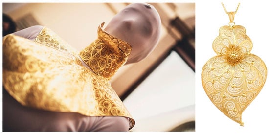
Biofiligree® draws specifically on Portuguese filigree, a longstanding metalworking tradition strongly associated with Portuguese cultural identity [35,36,37]. With historical origins extending back several millennia [38], the craft remains particularly associated with northern Portuguese production centres such as Gondomar and Póvoa de Lanhoso [39]. Its intricate metallic structures and culturally embedded motifs—including the Coração de Viana (Figure 1)—combine material craftsmanship with strong symbolic meaning [38,39,40]. Biofiligree® therefore explores whether this cultural and formal language can be translated into the structural architecture of an orthopaedic fixation plate, connecting jewellery, cultural heritage and biomedical engineering within a single design proposition.
Figure 1.
Typical filigree objects. Cervical filigree collar, by Olga Noronha [7] and Coração de Viana (Heart of Viana) (Author’s Work/Source).
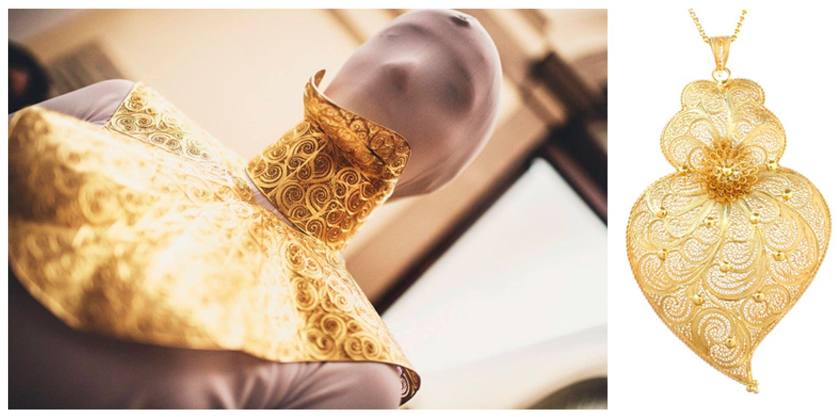
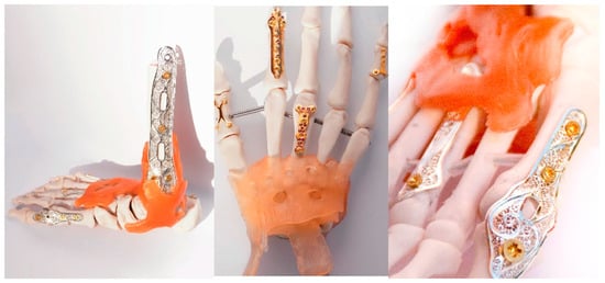
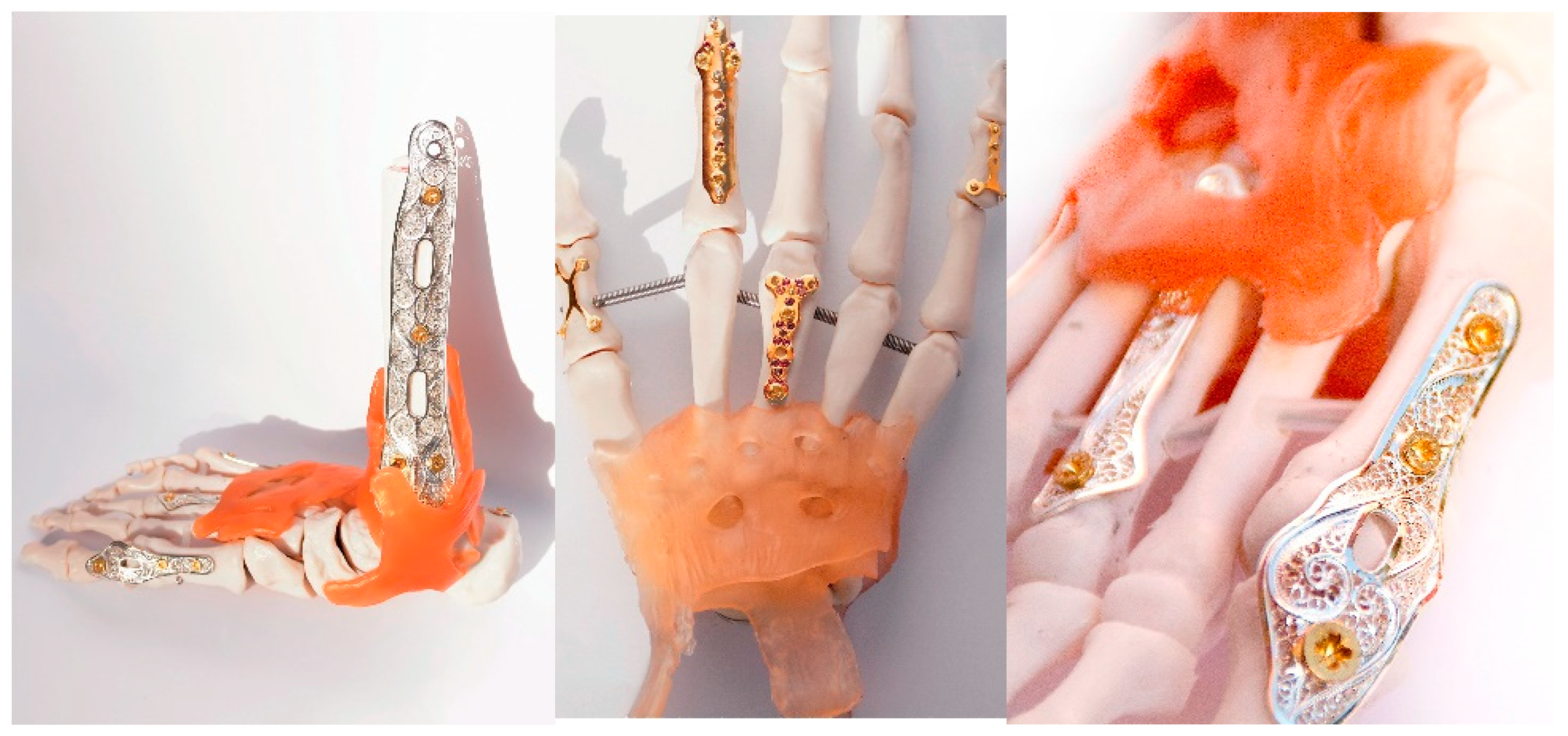
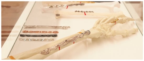
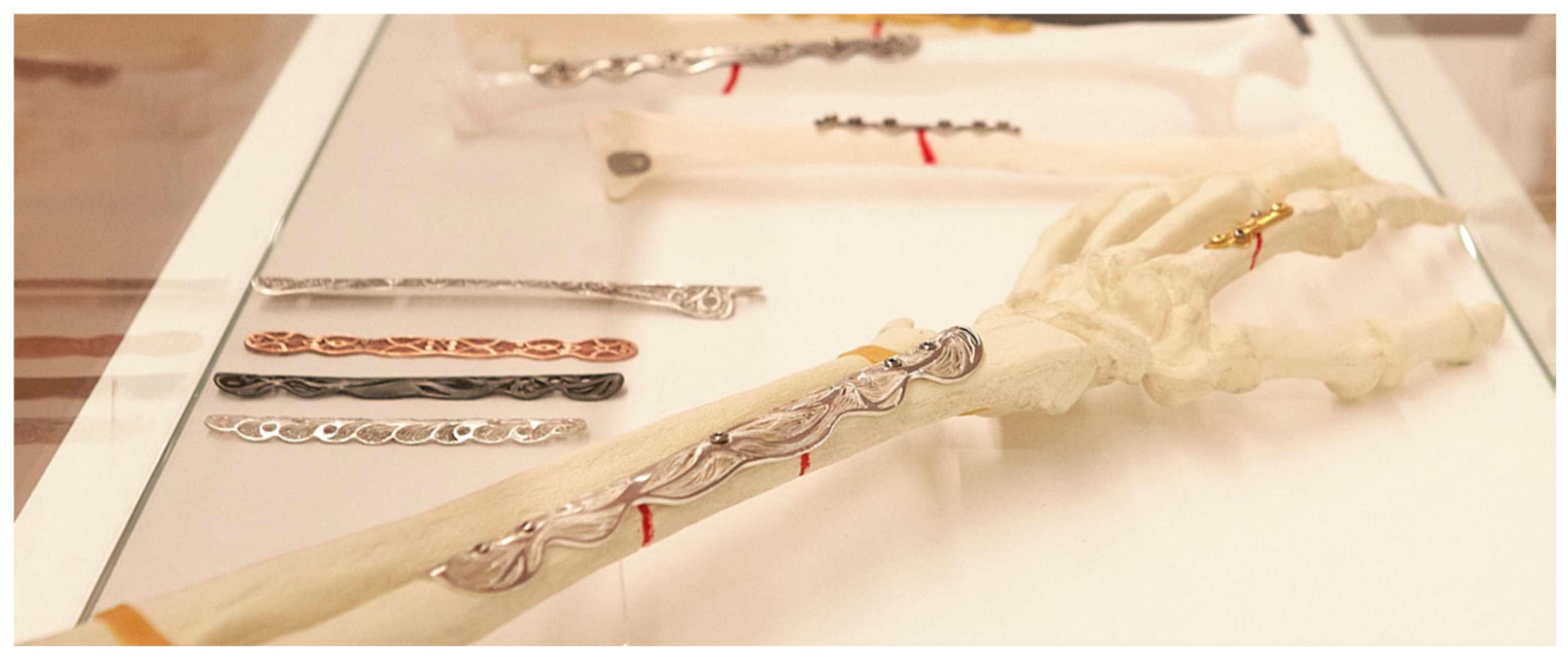
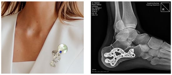
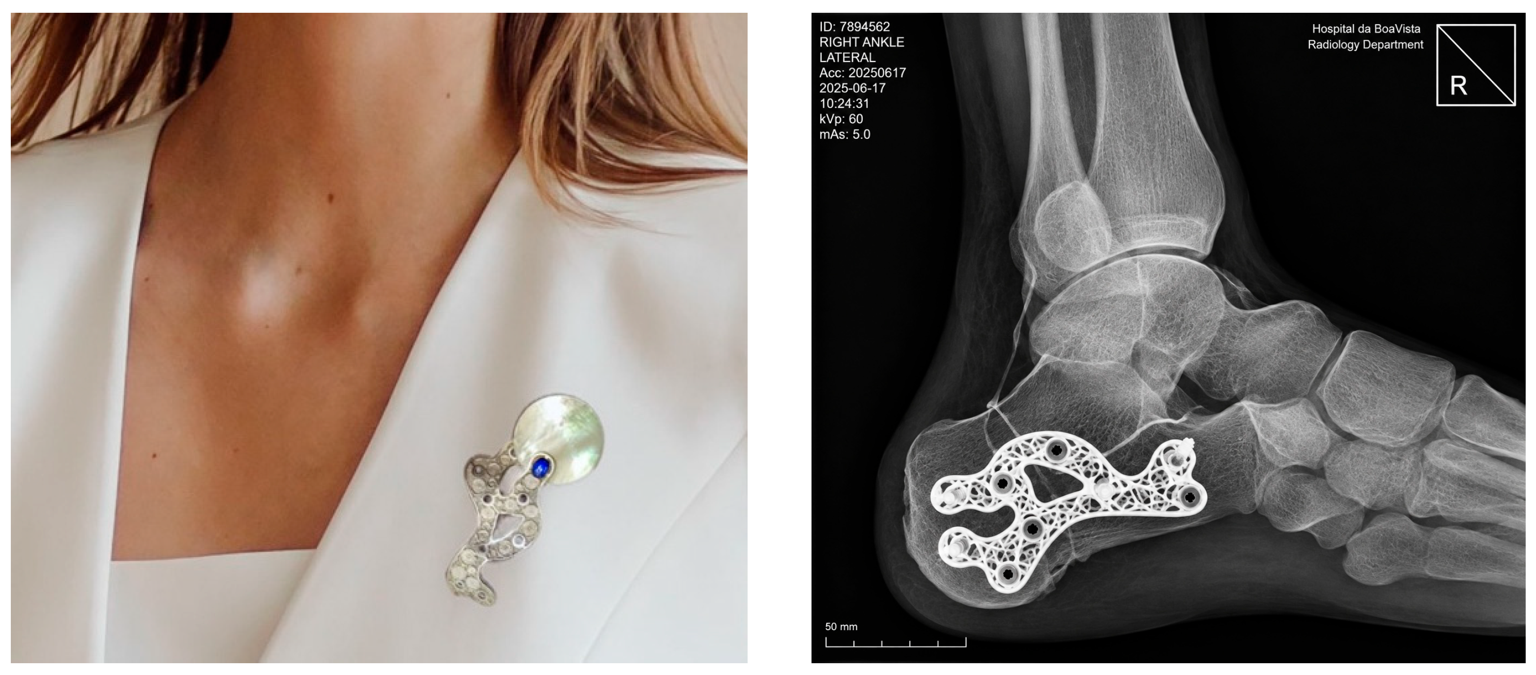
The proposed concept (Figure 2) consists of designing, developing and scientifically testing bone fixation plates using the traditional filigree technique and explore biofiligree bone fixation plates (Figure 3) as reliable and adequate bone fixating biodevices. Finally, once the bone has healed, the fixation plate can be extracted and transformed into wearable jewellery, such as a bracelet, ring or pendant, depending on its original size. Thus, silver and stainless steel filigree bone plates were designed and tested as fixation elements for fracture bone healing. In the initial exploratory phase, the SS and spiral motifs were assessed using basic three-point bending tests (ASTM F382-20: Standard specification and test method for metallic bone plates) [41] to evaluate rigidity and resistance to deformation when modelled as potential bone-plate geometries, in accordance with recognised mechanical testing procedures and minimum performance requirements for osteosynthesis plates [5,42,43,44,45]. As the motifs did not meaningfully alter stiffness or strength, both of which were largely dictated by the underlying skeletal geometry, further motif testing was discontinued. Consequently, for the proof-of-concept scenario, only one typical ulna-fracture plate and a commercial plate were employed. These tests constitute preliminary, design-research evaluations rather than clinical validation and are intended solely to demonstrate conceptual feasibility. The preliminary results of the mechanical tests on these plates answer the main research question: Can a filigree-inspired osteosynthesis plate geometry demonstrate biomechanically feasible behaviour under a defined fracture and loading configuration? Figure 4 shows different types of biojewellery plates manufactured. Figure 5 shows a proposal for a pin through the transformation of a calcaneal osteosynthesis plate into a jewel.
Figure 2.
Illustration showing the concept of the Biofiligree® bone fracture healing concept (Author’s Work/Source).
Figure 3.
Examples of bone fixation plates concerning the Biofiligree® concept. (Author’s Work/Source: Authors).
Figure 4.
Biofiligree® ulna plates (Author’s Work/Source).
Figure 5.
Proposal for a pin through the transformation of a calcaneal osteosynthesis plate (X-Ray simulation) into a Biofiligree® jewel. (Author’s Work/Source: Authors).
An important design principle of the Biofiligree® concept concerns the interface between the open metallic architecture and the underlying bone. The filigree regions are not intended to remain in direct contact with the bone surface where tissue formation could extend through the structural openings and subsequently compromise implant removal. The concept therefore incorporates a biopolymer interlayer between the metallic plate and the bone, physically separating the open filigree architecture from the underlying osseous surface. Direct metal–bone interaction is restricted primarily to structurally necessary regions, including solid plate areas associated with the fracture region and the screw-fixation sites. In particular, the plate region spanning the fracture is designed without open filigree features that could interfere with callus formation or provide pathways for newly formed bone to penetrate the plate architecture. This metal–polymer interface has been explored in previous design studies associated with the concept, although tissue response and implant removal have not been experimentally evaluated.
The proposed concept can also be applied in interphalangeal fixation, through the arthrodesis procedure, which is defined by cancelling the mobility of a joint with fixation plates and screws. Joint destruction with consequent loss of cartilage is generally caused by the presence of degenerative arthrosis induced by some type of trauma. Arthrodesis is considerably more frequent in the foot and ankle because they are load-bearing joints and therefore more prone to wear or fracture. The plates are designed to be lighter in weight, although not a crucial design variable, with the main surface constructed in fine, detailed filigree with surgical locking screws.
3. Materials and Methods
3.1. Study Design
A proof-of-concept study was conducted to investigate whether the Biofiligree® design approach could be translated into an osteosynthesis plate with mechanically plausible behaviour for fracture fixation. The study focused on an ulna fracture configuration and combined physical plate development with computational finite-element (FE) analysis.
The proof-of-concept configuration was developed in consultation with orthopaedic surgeons and biomedical-engineering researchers involved in the project. Their expertise informed the selection of the ulna as the anatomical model, the fracture configuration, the fixation arrangement and the mechanical parameters considered relevant to fracture stability and callus-mediated healing.
Three conditions were considered for numerical comparison: (i) an intact ulna; (ii) an ulna with a complete fracture stabilised using a conventional commercial plate; and (iii) the same fracture configuration stabilised using the Biofiligree® plate. The analysis was intended to evaluate the biomechanical behaviour of the specific Biofiligree® plate geometry under the investigated ulna fracture and static loading conditions, rather than to validate the Biofiligree® concept as a whole or to establish clinical efficacy, safety, or the benefits of personalised plate design.
3.2. Biofiligree® Plate Design and Fabrication
The Biofiligree® ulna plate was developed by combining the structural requirements of an osteosynthesis plate with the visual and geometric principles established through the Biofiligree® design concept described in Section 2. The plate was digitally modelled according to the anatomical curvature of the ulna and manufactured from 316L stainless steel. The fabrication workflow comprised: (i) digital modelling of the plate and its anatomical curvature; (ii) CNC laser cutting; (iii) manual finishing, motif placement and refinement, and surface polishing using jewellery-making techniques; and (iv) dimensional verification of plate thickness, curvature and screw-hole positioning.
For the ulna proof of concept, both the Biofiligree® and commercial plates had overall dimensions of 75 mm × 10 mm and a thickness of 1.5 mm. Fixation was represented using 2.0 mm diameter unicortical screws.
The FE model represented the structural skeleton of the Biofiligree® plate corresponding to the geometry intended for implantation and fracture fixation. Traditional filigree motifs were not included in the numerical model because these elements are not intended to be present during the implantation phase. Rather, the implanted structural skeleton provides the geometric framework for subsequent transformation of the retrieved plate into a jewellery artefact. Following fracture consolidation and plate removal, when clinically indicated, traditional filigree elements may be added to this skeleton using jewellery-making techniques. Accordingly, the FE analysis evaluates exclusively the mechanical behaviour of the load-bearing plate geometry present during fixation.
3.3. Ulna Fracture and Fixation Model
A synthetic composite ulna (Sawbones®, Pacific Research Laboratories, Inc., Vashon, WA, USA) was used as the anatomical reference for the proof-of-concept configuration. Synthetic composite bones provide reproducible geometry and material characteristics and are commonly used in biomechanical investigations and surgical training [46,47].
A complete fracture was defined in the middle segment of the ulna. The initial numerical model incorporated a 1 mm fracture gap, preventing contact between the opposing fracture surfaces. A subsequent condition incorporated hypothetical callus formation within the fracture region to examine the mechanical environment associated with an early stage of secondary fracture healing.
The same anatomical geometry and fracture configuration were used for the Biofiligree® and commercial fixation conditions to enable direct comparison of their mechanical responses.
3.4. Finite-Element Model
Three-dimensional FE models of the intact ulna and the two fixation configurations were developed to compare their mechanical behaviour under equivalent loading conditions. A mesh-convergence assessment was performed to evaluate the sensitivity of the principal numerical outcomes to spatial discretization. Six progressively refined meshes were generated while maintaining identical geometry, material properties, contact definitions, loading and boundary conditions. Convergence was assessed using maximum displacement (Table 1). The percentage variation between successive refinement levels was calculated, and the solution was considered sufficiently converged when further mesh refinement produced changes below 5%. The final mesh comprised 574,422 elements, approximately 80% of which had an aspect ratio below 3, indicating adequate element quality. This final discretization was subsequently used for the reported analyses.
Table 1.
Mesh convergence data. (Author’s Work/Source: Authors).
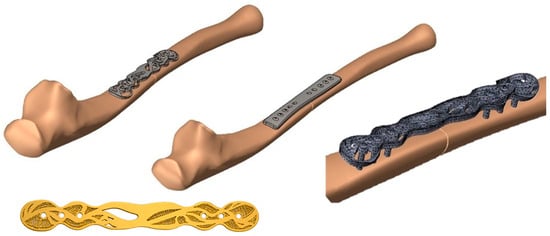
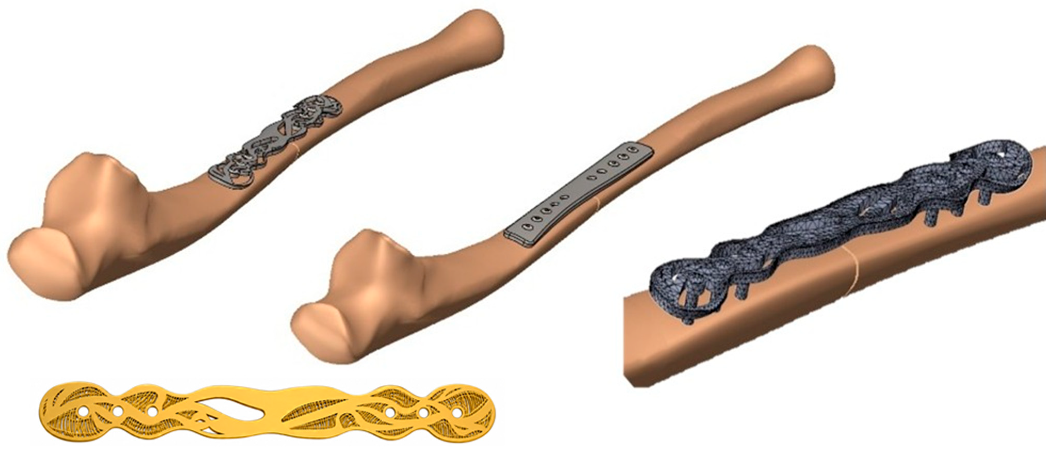
Cortical and cancellous bone were represented separately and considered sharing the interface nodes. The plates and fixation screws were positioned according to the corresponding fixation configurations. Figure 6 illustrates the digital ulna models with the commercial and Biofiligree® plates and provides a detailed view of the FE discretisation of the plate and screws.
Figure 6.
Digital ulna models (CAD) fitted with the commercial and BioFiligree® plates, including a detailed view of the FE mesh of the BioFiligree® structural plate skeleton and fixation screws, and the final BioFiligree® artefact (shown in gold) obtained after plate removal and the subsequent addition of traditional filigree elements. The decorative filigree elements were added only after plate removal and were therefore not included in the FE analysis [48]. (Author’s Work/Source: Authors).
3.5. Material Properties
All materials were assumed to exhibit homogeneous, isotropic and linear-elastic behaviour. The mechanical properties assigned to cortical bone, cancellous bone, the fixation plates, screws and bone callus are summarised in Table 2.
Table 2.
Mechanical properties used in numerical simulations. (Author’s Work/Source: Authors).
The callus was represented using two material states intended to approximate early stages of healing. An elastic modulus of 0.001 GPa was assigned to the initial stage, corresponding to approximately the first week, and 0.002 GPa to the subsequent stage, corresponding approximately two weeks to three. A Poisson’s ratio of 0.40 was used for both callus states.
3.6. Contact Conditions
Contact interactions were defined between the principal components of the fixation model. A friction coefficient of 0.30 was assigned to the bone–plate interface, while a coefficient of 0.10 was assigned to the screw–plate interface. Cortical and cancellous bone were bonded, and the bone–callus interface was represented using a bonded (glued) condition.
These contact definitions were maintained consistently between the commercial and Biofiligree® fixation models to enable comparison under equivalent numerical conditions.
3.7. Loading and Boundary Conditions
Boundary conditions were defined to reproduce a simplified loading configuration of the ulna while maintaining identical conditions for the intact, commercial-plate and Biofiligree®-plate models. The proximal ulna was constrained at the trochlear-notch region to represent its articulation with the humerus, while the distal region at the ulnar head was constrained to prevent rigid-body motion. A resultant force of 282 N was applied at the ulnar tuberosity at an angle of 45° relative to the longitudinal axis of the ulna. The magnitude of the force was estimated using a simplified static moment-equilibrium condition representing a 5 kg load acting at the hand, with an approximate hand-load moment arm of 300 mm and a muscle moment arm of 52 mm, resulting in an estimated muscular force of approximately 283 N. A value of 282 N was adopted for the numerical simulations. This magnitude is consistent with experimentally reported biceps-force ranges and their dependence on muscle length and fatigue [52], while the adopted loading configuration was informed by previous computational modelling of upper-limb fixation [53]. The loading condition was intended to provide a reproducible comparative scenario rather than reproduce the complete spectrum of in vivo upper-limb loading. Identical load magnitude, direction, application site and boundary conditions were maintained for all three configurations.
3.8. Mechanical Outcome Measures
The mechanical response of the three configurations was evaluated using the following numerical outcome measures:
- -
- Maximum displacement;
- -
- Strain energy density;
- -
- Von Mises stress;
- -
- Maximum and minimum principal stresses in bone;
- -
- Maximum and minimum principal strains in bone; and
- -
- Interfragmentary deformation within the fracture region.
Displacement and stress distributions were used to characterise global fixation behaviour and identify regions of local stress concentration. Principal bone strains were examined to assess differences in load transfer between the intact, commercial-plate and Biofiligree® configurations.
Interfragmentary motion (IFM) was defined as the maximum relative displacement between corresponding points on the opposing fracture surfaces, evaluated at the location exhibiting the greatest relative movement. Interfragmentary strain (IFS) was calculated as IFS (%) = IFM/g0 × 100, where g0 is the initial fracture gap. The initial gap was 1.0 mm in both plated configurations.
Principal bone strains were examined to assess differences in local bone deformation and load transfer between the intact, commercial-plate and Biofiligree® configurations and are reported in microstrain (µε). These local material strains were considered separately from interfragmentary motion (IFM), defined as the relative displacement across the fracture gap and expressed in millimetres, and interfragmentary strain (IFS), defined as the interfragmentary motion relative to the initial fracture-gap width and expressed as a percentage. Principal bone strain and IFS therefore represent distinct mechanical quantities and were not directly equated.
4. Results and Discussion
The numerical simulations compared the mechanical response of three configurations: the intact ulna, the fractured ulna fixed with the commercial plate, and the fractured ulna fixed with the Biofiligree® plate. The comparison focused on displacement, strain energy density (SED), von Mises stress, principal stress and principal strain in the bone, together with deformation across the fracture region. The results should be interpreted as a comparative numerical assessment under the specific material, contact, boundary and static loading conditions defined in the FE model, rather than as experimentally validated predictions of in vivo behavior.
Mechanical stability is an important consideration in fracture fixation because both excessive and insufficient construct stiffness can modify the mechanical environment at the fracture site [54,55]. The present analysis therefore focuses primarily on the relative differences between the commercial and Biofiligree® configurations when subjected to identical numerical conditions. The principal results are summarised in Table 3.
Table 3.
Numerical results obtained for the intact ulna and for the different plated conditions. (Author’s Work/Source: Authors).
The values reported in Table 2 represent the maximum or minimum values extracted from the predefined regions specified in the table note. Because local extrema can be influenced by geometry, contact conditions and mesh discretisation, particularly for stress, these values are interpreted together with their spatial distributions rather than as isolated indicators of structural performance.
4.1. Global Mechanical Response and Construct Compliance
Maximum displacement differed between the intact and plated configurations. The intact ulna exhibited a maximum displacement of 0.743 mm, whereas the commercial and Biofiligree® fixation configurations produced maximum displacements of 1.695 and 1.801 mm, respectively. The greater displacement obtained with the Biofiligree® configuration indicates a more compliant construct under the simulated loading condition.
This difference is relatively modest in absolute terms—the Biofiligree® configuration exhibited approximately 6.3% greater maximum displacement than the commercial configuration—but demonstrates that modification of the structural plate architecture can alter the global mechanical response of the fixation system. The result should not, however, be interpreted as evidence that greater displacement is inherently beneficial. In fracture fixation, construct compliance must remain compatible with adequate mechanical stability, and the appropriate level depends on fracture configuration, anatomical location, fixation strategy and healing mechanism [54,55,56,57,58,59].
The SED results provide an additional indication of differences in mechanical response. The commercial fixation exhibited the highest value (71.7 × 10³ J/m3), followed by the Biofiligree® configuration (65.3 × 10³ J/m3), whereas the intact ulna exhibited 37.3 × 10³ J/m3. The fracture region showed a substantially lower value (8.2 × 10³ J/m3), reflecting the local loss of structural continuity. These differences further demonstrate that the two fixation architectures modify load transfer and energy storage within the bone–plate system differently.
Taken together, the displacement and SED results indicate that the Biofiligree® structural skeleton produces a mechanically distinct and somewhat more compliant fixation response than the commercial plate under the conditions investigated. This constitutes a relative numerical comparison and does not establish superiority of either fixation strategy. The commercial plate exhibited lower IFM than the Biofiligree® plate (0.052 versus 0.103 mm), consistent with a stiffer fracture-fixation response. Correspondingly, the Biofiligree® configuration produced greater interfragmentary deformation under the investigated loading condition. These differences are interpreted as comparative mechanical observations and should not be considered direct indicators of fracture-healing outcome.
4.2. Plate Stress Distribution and Structural Implications
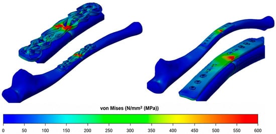
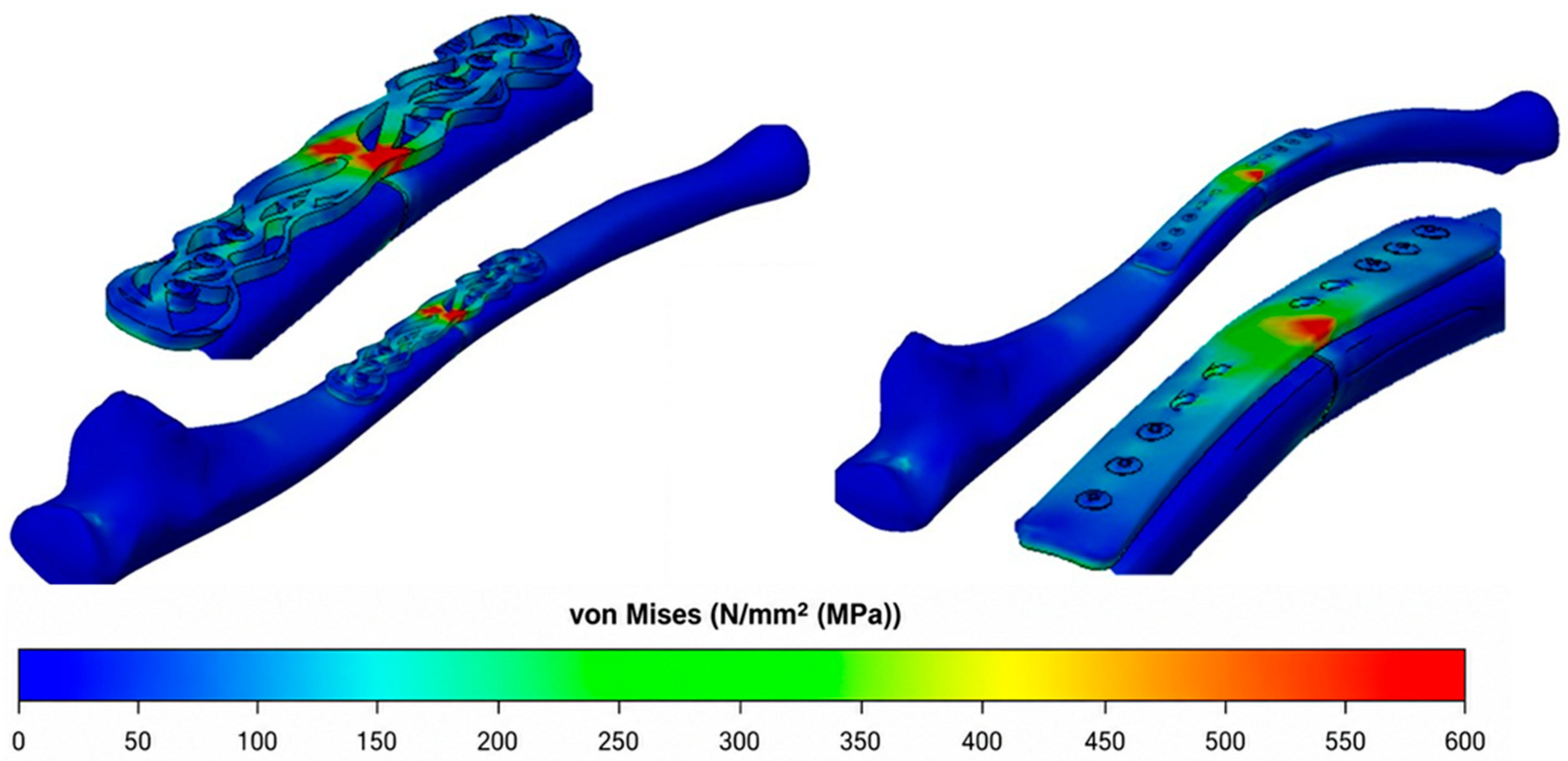
The von Mises stress distribution revealed a more important difference between the two plate architectures. The commercial plate exhibited a comparatively more uniform stress distribution, with a maximum value of 409 MPa, whereas the Biofiligree® plate developed a local maximum of approximately 600 MPa within a geometrically discontinuous region of the structural plate skeleton (Figure 7).
Figure 7.
Equivalent von Mises stress distribution in the commercial and Biofiligree® plates, showing differences in stress distribution and the local stress concentration identified in the Biofiligree® structural skeleton [48]. (Author’s Work/Source: Authors).
The local concentration should be attributed to the open architecture and geometric discontinuities of the load-bearing skeleton, including changes in section and load-transfer pathways, rather than to traditional filigree motifs. As clarified in the design and modelling sections, the FE model represents the structural skeleton implanted during fracture fixation. Traditional filigree motifs are added only after plate removal and therefore neither contribute to the implanted mechanical response nor form part of the present numerical model.
The magnitude of the approximately 600 MPa peak requires particular consideration in relation to the mechanical properties of 316L stainless steel. The yield strength of 316L varies according to material condition, processing history and manufacturing route; consequently, a single yield value cannot be assumed to represent every potential implementation of the proposed plate. Nevertheless, the predicted peak is sufficiently high to indicate that local yielding may occur for some 316L conditions. The present geometry should therefore not be interpreted as demonstrating structural safety. Rather, this local maximum identifies a mechanically critical region requiring geometric optimization.
This interpretation is further constrained by the constitutive model adopted in the simulations. The metallic components were represented as homogeneous, isotropic and linearly elastic. Consequently, the FE analysis cannot reproduce plastic deformation or the associated redistribution of stress that could occur if the local stress exceeded the yield strength of the selected material condition. An elastoplastic analysis would be necessary to characterise post-yield behaviour once the definitive 316L condition and manufacturing process have been established. Within the present comparative numerical proof of concept, the approximately 600 MPa value should therefore be regarded primarily as a critical design indicator, rather than as a prediction of failure or evidence of acceptable structural performance.
The principal stresses calculated in the bone also demonstrate differences in load transfer. The commercial configuration produced the highest maximum principal stress (+49 MPa), compared with +27 MPa for the Biofiligree® configuration and +30 MPa for the intact ulna. Minimum principal stresses were similar for the two plated configurations (−35 and −36 MPa for the commercial and Biofiligree® plates, respectively). These findings indicate that changes in plate architecture can substantially modify the distribution of tensile and compressive stresses in the underlying bone. However, lower or more intact-like stress values should be regarded as mechanical observations rather than direct indicators of improved biological or clinical performance.
The geometry of the structural plate skeleton therefore emerges as a central design variable. The dimensions and continuity of load-bearing regions, transitions between solid and open areas and geometry surrounding the fracture region influence both global construct compliance and local stress concentration. Subsequent design iterations should therefore seek to reduce abrupt geometric discontinuities and improve load transfer through critical regions while preserving the intended degree of construct compliance. This represents an engineering optimisation problem in which flexibility and mechanical resistance must be considered simultaneously.
The significance of the local stress concentration must also be considered in relation to cyclic loading. The Biofiligree® plate is conceived as a temporary fixation device during fracture consolidation rather than as a permanent load-bearing implant. During recovery, functional loading is progressively managed according to clinical assessment, and patients are advised to avoid activities that could impose excessive loading on the fixation construct. These conditions may reduce the magnitude and duration of the most demanding loading events experienced by the plate.
Nevertheless, repeated physiological loading remains unavoidable throughout the implantation period. The present static FE analysis cannot therefore establish fatigue resistance or predict implant service life. Given the local stress concentration identified in the Biofiligree® geometry, subsequent development should prioritise geometric optimisation followed by nonlinear numerical modelling, experimental mechanical validation, and cyclic/fatigue testing under physiologically representative loading conditions.
4.3. Principal Strain and Fracture-Region Mechanics
The mechanical environment within the fracture region was further examined through the principal bone strain distributions. Principal bone strain and interfragmentary strain are distinct mechanical parameters that describe different aspects of the fracture-region mechanical environment. Principal bone strain represents local deformation within the bone material and is reported in microstrain (µε), whereas interfragmentary strain represents relative deformation across the fracture gap and is expressed as a percentage. Both parameters are relevant to fracture mechanobiology because they contribute to the local mechanical conditions experienced during secondary healing [43,55,56,57,58]. However, fracture healing is a dynamic biological process influenced by vascularisation, cellular activity, tissue differentiation, loading history, and patient-specific factors. FE-derived strain values should therefore be interpreted as mechanical indicators rather than direct predictors of tissue formation or clinical healing.
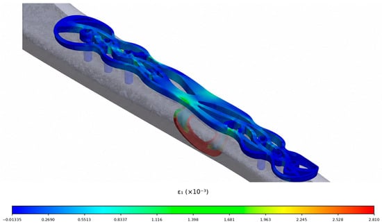
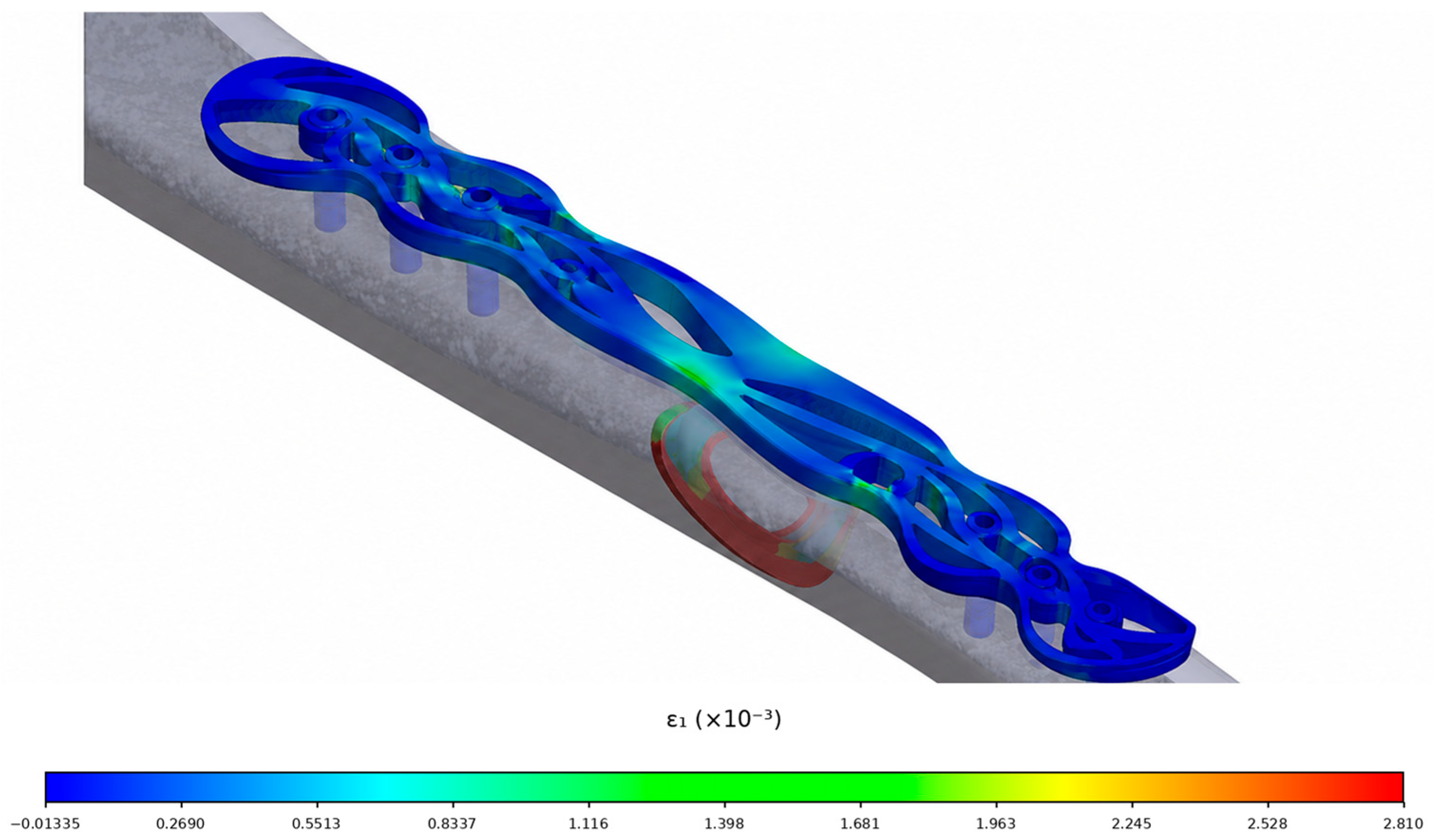
The Biofiligree® configuration generated a maximum principal bone strain of 3615 µε, compared with 1923 µε for the commercial fixation and 3895 µε for the intact ulna (Table 2; Figure 8). Relative to the intact condition, the maximum principal bone strain differed by approximately −7% for the Biofiligree® configuration and −51% for the commercial configuration. The Biofiligree® model therefore reproduced the intact maximum principal bone strain magnitude more closely under the specific numerical conditions investigated.
Figure 8.
Maximum principal bone strain (µε) field in the fracture region for the investigated fixation configurations. The distributions are presented as comparative numerical indicators of the local mechanical environment and should not be interpreted as interfragmentary strain or as direct predictors of fracture healing [48]. (Author’s Work/Source: Authors).
For minimum principal bone strain, the intact ulna exhibited −7746 µε, compared with −2686 µε for the Biofiligree® configuration and −9679 µε for the commercial plate. These differences demonstrate that neither fixation system reproduced the complete intact strain state and that the relative behaviour depends on whether tensile or compressive principal strain is considered. This observation reinforces the importance of evaluating the complete strain field rather than interpreting a single maximum value as evidence of mechanical or biological superiority.
Earlier mechanostat-based frameworks have related ranges of mechanical strain to adaptive bone responses [57,60], while more recent experimental and computational studies demonstrate that mechanobiological responses also depend on loading frequency, spatial location, strain direction, cellular environment, fluid flow and molecular signalling [61,62,63,64,65]. Accordingly, the strain values obtained in the present model should not be assigned directly to a specific healing outcome. Their principal relevance here is comparative: they demonstrate how modification of plate architecture alters the mechanical strain field generated in the bone under otherwise equivalent numerical conditions.
4.4. Interfragmentary Strain and Mechanobiological Interpretation
Interfragmentary strain (IFS) provides a complementary measure of fracture-region mechanics and was determined from the relative deformation across the fracture gap, expressed as a percentage of the initial gap width. Interfragmentary strain was 10.3% for the Biofiligree® configuration and 5.2% for the commercial plate under the simulated loading condition. The higher IFS obtained with the Biofiligree® configuration is consistent with its greater construct compliance. However, these values should be interpreted as comparative mechanical indicators under the investigated loading condition rather than as direct predictors of tissue differentiation or fracture-healing outcome. According to established interfragmentary-strain concepts, values within these ranges may be mechanically compatible with tissue differentiation during secondary fracture healing [42,56].
It is important to distinguish IFS, expressed as a percentage of the initial fracture gap, from the principal bone strain values reported in microstrain (µε) in Section 4.3. These quantities describe different aspects of the mechanical response and should not be directly equated or converted into one another. IFS characterises relative deformation across the fracture interface, whereas principal bone strain describes local deformation within the bone material represented in the FE model.
The Biofiligree® configuration therefore produced greater global displacement and a different fracture-region strain distribution than the commercial fixation. These results are consistent with its more compliant structural response. Greater compliance may permit increased interfragmentary deformation, but this cannot automatically be interpreted as a more favourable healing environment. Excessive deformation can compromise fixation stability, while insufficient deformation may alter the mechanical conditions associated with secondary healing [54,55,56,57,58,59]. The relevant engineering objective is therefore not to maximise micromotion but to achieve an appropriate balance between construct stability, interfragmentary mechanics, and structural resistance.
The present results indicate that the investigated Biofiligree® geometry achieved interfragmentary deformation within mechanically plausible ranges under the simulated loading condition, while simultaneously developing a substantial local stress concentration in the plate. This combination highlights the central mechanical trade-off identified by the study: increased construct compliance must be balanced against local structural demand.
Consequently, the current Biofiligree® geometry should be regarded as a starting point for further optimisation rather than a mechanically validated final implant design. Subsequent iterations should specifically address the geometry around the fracture region and other areas of stress concentration, with the objective of reducing peak stresses while maintaining appropriate construct compliance. Such designs should then be evaluated through nonlinear FE analysis, experimental testing of the complete bone–plate construct, and cyclic/fatigue loading before conclusions regarding physical or clinical performance can be drawn.
Overall, the simulations demonstrate that the specific Biofiligree® structural plate geometry investigated produces a mechanically distinct response from the conventional plate under identical numerical conditions. The results provide preliminary numerical evidence of biomechanical feasibility under the specific fracture, geometry, loading, and modelling conditions investigated and identify specific design parameters requiring further optimisation. They do not constitute experimental validation of the FE model, demonstrate clinical efficacy or improved fracture healing, or establish the performance of Biofiligree® geometries in other fracture configurations or anatomical locations.
5. Limitations
This study has several limitations that should be considered when interpreting the findings. First, the present work is a comparative numerical proof-of-concept investigation, and the FE model has not been experimentally validated. Consequently, the absolute mechanical predictions remain dependent on the simplifying assumptions adopted for material properties, contact conditions, boundary conditions and loading. Although identical modelling conditions were applied to the commercial and Biofiligree® configurations to enable direct numerical comparison, subsequent mechanical testing of the Sawbones®–plate assemblies and comparison of experimentally measured stiffness and displacement with the FE predictions will be required to validate the model. The present study therefore does not constitute experimental or clinical validation, and no human or animal testing was performed.
Second, only one anatomical site, one fracture configuration, and one Biofiligree® plate geometry was examined; the findings therefore cannot be generalised to other fracture patterns, anatomical regions or plate architectures. Third, the bone materials were modelled as homogeneous, isotropic and linearly elastic, whereas biological bone exhibits heterogeneous, anisotropic, and time-dependent behaviour. The callus was similarly represented using simplified material properties and bonded interfaces. Fourth, the FE analysis considered a single static loading condition representing a simplified muscular loading scenario and therefore does not reproduce the variable and cyclic physiological loads experienced during daily activity. Consequently, the present analysis cannot predict fatigue behaviour or implant service life. This limitation is particularly relevant because the Biofiligree® plate exhibited local stress concentrations approaching 600 MPa, indicating that geometric optimisation is required before physical implantation could be considered. Future validation should therefore include cyclic mechanical testing and fatigue-oriented numerical analyses under physiologically representative loading conditions. Nevertheless, the Biofiligree® plate is conceived as a temporary fixation device during fracture consolidation rather than as a permanent load-bearing implant. Its intended implantation period is therefore relatively limited, and during fracture recovery, functional loading is progressively managed according to clinical assessment, with patients advised to avoid activities that could subject the fixation construct to excessive loading. These considerations may reduce the magnitude and duration of the most demanding loading conditions experienced by the plate, although they do not eliminate cyclic loading or the need for dedicated fatigue evaluation. Fifth, the broader Biofiligree® concept incorporates a biopolymer interlayer intended to separate the open metallic architecture from the underlying bone and thereby limit direct interaction between newly formed tissue and the plate openings. However, this component was not represented in the present FE model because the numerical comparison was designed to isolate the influence of plate geometry under equivalent modelling conditions. Its effects on load transfer, tissue interaction, soft-tissue adhesion or ingrowth, and subsequent implant removal therefore remain to be established experimentally.
Accordingly, the findings demonstrate only the biomechanical feasibility of the investigated plate geometry under the specific numerical conditions modelled and should not be extrapolated to other Biofiligree® geometries, fracture types, anatomical locations, loading conditions or clinical outcomes.
Finally, the proposed emotional, symbolic, and psychotherapeutic benefits of transforming a fixation plate into a post-treatment jewellery artefact were not evaluated in the present study and remain conceptual hypotheses requiring dedicated patient-centred research. Accordingly, the findings should be interpreted as preliminary numerical evidence of biomechanical plausibility within the specific computational conditions investigated, rather than as experimentally validated evidence of biomechanical performance, clinical safety, effectiveness, improved fracture healing, or therapeutic benefit.
6. Conclusions
This study investigated the biomechanical feasibility of a specific Biofiligree® osteosynthesis plate geometry for an ulna fracture configuration under static loading conditions. The concept integrates a filigree-inspired design language with the structural requirements of fracture fixation while providing the geometric framework for potential post-removal transformation into a personalised jewellery artefact.
Under the conditions investigated, finite-element analysis demonstrated that the Biofiligree® plate produced a more compliant mechanical response than the conventional commercial plate in comparison with intact ulna. Maximum principal strain in the bone was closer to that obtained for the intact ulna, while interfragmentary deformation remained within mechanically plausible ranges across most of the fracture interface. These findings indicate that the investigated geometry can provide fracture stabilisation while permitting greater deformation than the conventional fixation configuration.
This increased compliance was, however, accompanied by local stress concentrations approaching 600 MPa in the Biofiligree® plate. The current geometry therefore requires further structural optimisation, particularly in regions of stress concentration, to improve the balance between construct compliance and mechanical resistance. Moreover, because the analysis considered a single static loading condition, the results do not establish fatigue resistance, implant service life or structural safety under repeated physiological loading.
The findings should consequently be interpreted as preliminary numerical evidence of the biomechanical feasibility of the specific Biofiligree® plate geometry and fracture configuration investigated, rather than as validation of the Biofiligree® concept as a whole or evidence of clinical efficacy, improved fracture healing, or applicability to other anatomical locations and fracture configurations. The potential emotional and symbolic value associated with post-removal transformation of the plate into a jewellery artefact likewise remains a conceptual proposition and was not evaluated in the present study.
Further development should prioritise geometric optimisation, cyclic and fatigue testing, experimental biomechanical validation, evaluation of the proposed biopolymer interface and tissue–implant interactions and assessment of manufacturing and material requirements. Subject to such validation, the present findings provide a basis for continued investigation of how design, cultural references and biomedical engineering may be integrated in the development of alternative approaches to osteosynthesis devices.
7. Ethical Considerations
This study involved no human or animal subjects, no patient data and no clinical procedures. All experimental work was carried out exclusively on synthetic Sawbones® models and non-implantable prototypes. Accordingly, formal ethical approval was not required under institutional and international guidelines [66,67]. Nonetheless, ethical considerations were integral to the project. Orthopaedic medical collaborators were consulted throughout to ensure responsible representation of surgical contexts and the work is explicitly framed as a speculative, design-led proof of concept rather than a clinically deployable device. This approach aligns with ethical norms in speculative biomedical design [68] and with broader discussions in bioethics regarding the cultural and symbolic dimensions of bodily interventions [69].
Author Contributions
Conceptualization, O.N. and J.A.S.; methodology, O.N., A.R. and J.A.S.; software, R.C.; validation, J.A.S., A.R., O.B.S. and J.C.N.; formal analysis, O.N., A.R. and J.A.S.; investigation, O.N., R.C., A.R. and J.A.S.; resources, J.A.S.; data curation, A.R., J.A.S., O.B.S. and J.C.N.; writing—original draft preparation, O.N.; writing—review and editing, J.A.S., O.B.S. and J.C.N.; visualization, R.C. and A.R.; supervision, O.N.; project administration, J.A.S.; funding acquisition, J.A.S. All authors have read and agreed to the published version of the manuscript.
Funding
This work was supported by the Fundação para a Ciência e a Tecnologia under Grant 2023.15616.PEX.
Data Availability Statement
Data are contained within the article.
Conflicts of Interest
The authors declare no conflict of interest.
References
- Zhang, H.; Xu, S.; Ding, X.; Xiong, M.; Duan, P. Design of internal fixation implants for fracture: A review. J. Orthop. Transl. 2025, 50, 306–332. [Google Scholar] [CrossRef] [Scilit] [PubMed]
- Mehboob, A.; Barsoum, I.; Al-Rub, R.K.A. Review on lower limb bone fracture fixation: Biomechanics, design, and advancements in additive manufacturing for implants. Mater. Des. 2025, 260, 115001. [Google Scholar] [CrossRef] [Scilit]
- Cook, B.; Patel, N.H.; Nayar, S.K.; Patel, N. Plate versus intramedullary nail fixation for distal fibula fractures: A systematic review and meta-analysis of randomised controlled trials. Cureus 2025, 17, e90130. [Google Scholar] [CrossRef] [Scilit] [PubMed]
- Rüedi, T.P.; Murphy, W.M.; Colton, C.L.; Fackelman, G.E.; Harder, Y. AO Principles of Fracture Management; Thieme: Stuttgart, Germany, 2000; Volume 864. [Google Scholar]
- Talaia, P.M.; Ramos, A.; Abe, I.; Schiller, M.W.; Lopes, P.; Nogueira, R.N.; Pinto, J.L.; Claramunt, R.; Simões, J.A. Plated and intact femur strains in fracture fixation using fiber Bragg gratings and strain gauges. Exp. Mech. 2007, 47, 355–363. [Google Scholar] [CrossRef] [Scilit]
- Lacroix, D.; Prendergast, P.J.; Li, G.; Marsh, D. Biomechanical model to simulate tissue differentiation and bone regeneration: Application to fracture healing. Med. Biol. Eng. Comput. 2002, 40, 14–21. [Google Scholar] [CrossRef] [Scilit] [PubMed]
- Noronha, O. ‘Becoming The Body’: An Investigation into the Possibilities and Affordances of “Medical Jewellery”. Doctoral Dissertation, Goldsmiths, University of London, London, UK, August 2018. [Google Scholar]
- Kerridge, T. Biojewellery: Jewellery, Biomaterials and the Body 2014. Available online: https://www.materialbeliefs.co.uk/biojewellery/images/exhibit/biojewellery-booklet.pdf (accessed on 6 August 2026).
- Thompson, I.; Stott, N.; Kerridge, T. Biojewellery: Designing rings with bioengineered bone and tissue. In Oral & Maxillofacial Surgery; King’s College London: London, UK, 2006. [Google Scholar]
- Zellweger, C. Jewellery as Prostheses [Project]. Sheffield Hallam University. 2002. Available online: https://www.shu.ac.uk/art-design-media-research-centre/archive/jewellery-as-prostheses (accessed on 6 August 2026).
- Porter, V.; Saif, L.; Savage-Smith, E. Medieval Islamic amulets, talismans, and magic. In A Companion to Islamic Art and Architecture; John Wiley and Sons: Hoboken, NJ, USA, 2017; pp. 521–557. [Google Scholar]
- den Besten, L. On Jewellery: A Compendium of International Contemporary Art Jewellery; Arnoldsche: Stuttgart, Germany, 2011. [Google Scholar]
- Skinner, D. Contemporary Thinking for Contemporary Jewelry. In Contemporary Jewelry in Perspective; Art Jewelry Forum: San Francisco, CA, USA, 2016; pp. 187–227. [Google Scholar]
- Scarpitti, C. The Contemporary Jewelry Perspective. Meanings and evolutions of a necessary practice. J. Jewel. Res. 2021, 4, 59–76. [Google Scholar]
- Sofaer, J.R. The Body as Material Culture: A Theoretical Osteoarchaeology; Cambridge University Press: Cambridge, UK, 2006; Volume 4. [Google Scholar]
- Csordas, T.J. (Ed.) Embodiment and Experience: The Existential Ground of Culture and Self; Cambridge University Press: Cambridge, UK, 1994; Volume 2. [Google Scholar]
- Douglas, M. Natural Symbols; Routledge: Oxford, UK, 2002. [Google Scholar]
- Turner, T.S. The social skin. HAU J. Ethnogr. Theory 2012, 2, 486–504. [Google Scholar] [CrossRef] [Scilit]
- Miller, D. The Comfort of Things; Polity: Cambridge, UK, 2008. [Google Scholar]
- Untracht, O. Jewelry Concepts & Technology; Doubleday: New York, NY, USA, 2011. [Google Scholar]
- Woodward, S. Why Women Wear What They Wear; Berg: Oakland, CA, USA, 2007. [Google Scholar]
- Noronha, O. To What Extent Can Jewellery, Science and Technology Come Together in Relation to the Human Body? Master Thesis, Goldsmiths, University of London, London, UK, 2012. [Google Scholar]
- Evans, J. A History of Jewellery; Victoria & Albert Museum: London, UK, 2025. [Google Scholar]
- Standish, C.D.; Dhuime, B.; Hawkesworth, C.J.; Pike, A.W. A non-local source of Irish Chalcolithic and Early Bronze Age gold. In Proceedings of the Prehistoric Society; Cambridge University Press: Cambridge, UK, 2015; Volume 81, pp. 149–177. [Google Scholar]
- Olsen, K.; Bohr, J. Hidden beauty in twisted viking neck rings. arXiv 2010, arXiv:1008.4306. [Google Scholar]
- Kayani, S.A. Mineralogical and thermal analyses of a bangle shard from Harrappa, an Indus Valley Settlement in Pakistan. arXiv 2012, arXiv:1202.3004. [Google Scholar]
- Cifarelli, M. Adornment, identity, and authenticity: Ancient jewelry in and out of context. Am. J. Archaeol. Online Mus. Rev. 2010, 114, 1–9. [Google Scholar]
- Ogden, A. Advances in the palaeopathology of teeth and jaws. In Advances in Human Palaeopathology; John Wiley and Sons: Hoboken, NJ, USA, 2007; pp. 283–307. [Google Scholar]
- Chaya, A.; Yoshizawa, S.; Verdelis, K.; Myers, N.; Costello, B.J.; Chou, D.T.; Pal, S.; Maiti, S.; Kumta, P.M.; Sfeir, C. In vivo study of magnesium plate and screw degradation and bone fracture healing. Acta Biomater. 2015, 18, 262–269. [Google Scholar] [CrossRef] [Scilit] [PubMed]
- Cherry, N. Grow Your Own—Angiogenetic Body Adornment. SCAN J. Media Arts Cult. 2006, 3. Available online: https://scan.net.au/scan/journal/display.php?journal_id=86 (accessed on 6 August 2026).
- Ferrara, N. (Ed.) Angiogenesis: From Basic Science to Clinical Applications; CRC Press: Boca Raton, FL, USA, 2006. [Google Scholar]
- Brunner, C.F.; Weber, B.G. Special Techniques in Internal Fixation; Springer: Berlin/Heidelberg, Germany, 2013. [Google Scholar]
- Prendergast, P.J. Mechanics applied to skeletal ontogeny and phylogeny. Meccanica 2002, 37, 317–334. [Google Scholar] [CrossRef] [Scilit]
- Huiskes, R.; Driel, W.V.; Prendergast, P.J.; Søballe, K. A biomechanical regulatory model for periprosthetic fibrous-tissue differentiation. J. Mater. Sci. Mater. Med. 1997, 8, 785–788. [Google Scholar] [CrossRef] [Scilit] [PubMed]
- Miranda, C. Estudo de Padrões de Filigrana Para Aplicações em Joalharia Biomédica. Master Thesis, Escola Superior de Artes e Design, Matosinhos, Portugal, 2023. [Google Scholar]
- Rodrigues, R. The Social Life of Filigree Objects. Doctoral Dissertation, University of Birmingham, Birmingham, UK, 2022. [Google Scholar]
- Ratten, V.; Braga, V. Internationalization through digital empowerment for women filigree jewelry artisan entrepreneurs in Portugal. Thunderbird Int. Bus. Rev. 2024, 66, 419–427. [Google Scholar] [CrossRef] [Scilit]
- Soares, T. The History of Filigree—A Symbol of Portuguese Love Mar d’Estórias. 16 January 2024. Available online: https://www.mardestorias.com/en/the-history-of-filigree-a-symbol-of-portuguese-love/ (accessed on 6 August 2026).
- House of Filigree. The Ancient Art of Filigree. Available online: https://houseoffiligree.com/en/pages/conhecer-a-filigrana (accessed on 6 August 2026).
- Marques, J.M. Filigrana/Filigree—Twisted Strands of the Portuguese Soul Portico. 23 November 2021. Available online: https://www.portico-magazine.com/articles/filigrana-filigree-twisted-strands-of-the-portuguese-soul (accessed on 6 August 2026).
- ASTM F382-20; Standard Specification and Test Method for Metallic Bone Plates. ASTM International: West Conshohocken, PA, USA, 2020.
- Perren, S.M. Evolution of the internal fixation of long bone fractures: The scientific basis of biological internal fixation: Choosing a new balance between stability and biology. J. Bone Jt. Surg. Br. Vol. 2002, 84, 1093–1110. [Google Scholar] [CrossRef] [Scilit] [PubMed]
- Brunette, D.M.; Tengvall, P.; Textor, M.; Thomsen, P. Titanium in Medicine: Material Science, Surface Science, Engineering, Biological Responses and Medical Applications; Springer: Berlin/Heidelberg, Germany, 2001; p. 232. [Google Scholar]
- Friis, E. Mechanical Testing of Orthopaedic Implants; Woodhead Publishing: Sawston, UK, 2017. [Google Scholar]
- Gautier, E. Biomechanics of osteosynthesis by screwed plates. In Biomechanics and Biomaterials in Orthopedics; Springer: London, UK, 2016; pp. 341–372. [Google Scholar]
- Heiner, A.D. Structural properties of fourth-generation composite femurs and tibias. J. Biomech. 2008, 41, 3282–3284. [Google Scholar] [CrossRef] [Scilit] [PubMed]
- Gardner, M.P.; Chong, A.C.; Pollock, A.G.; Wooley, P.H. Mechanical evaluation of large-size fourth-generation composite femur and tibia models. Ann. Biomed. Eng. 2010, 38, 613–620. [Google Scholar] [CrossRef] [Scilit] [PubMed]
- Noronha, O.; Miranda, C.; Coelho, R.; Ramos, A.; Simões, J.; Noronha, J.C. A new concept of bone biofiligree fixation plate for cubital fractures. In Congress of the Portuguese Society of Biomechanics; Springer Nature: Cham, Switzerland, 2023; pp. 131–141. [Google Scholar]
- Rho, J.Y. An ultrasonic method for measuring the elastic properties of human tibial cortical and cancellous bone. Ultrasonics 1996, 34, 777–783. [Google Scholar] [CrossRef] [Scilit] [PubMed]
- Kurgan, N.; Varol, R. Mechanical properties of P/M 316L stainless steel materials. Powder Technol. 2010, 201, 242–247. [Google Scholar] [CrossRef] [Scilit]
- Reichel, H.; Lebek, S.; Alter, C.; Hein, W. Biomechanical and densitometric bone properties after callus distraction in sheep. Clin. Orthop. Relat. Res. 1998, 357, 237–246. [Google Scholar] [CrossRef] [Scilit] [PubMed]
- Yamazaki, T.; Matsuura, Y.; Suzuki, T.; Ohtori, S. Evaluation of fixation after plating of distal radius fractures—A validation study. Comput. Methods Biomech. Biomed. Eng. 2021, 24, 1687–1692. [Google Scholar] [CrossRef] [Scilit] [PubMed]
- Carr, J.C.; Ye, X.; Tharp, H.M. Biceps brachii muscle length affects force steadiness with and without fatigue. J. Sci. Sport Exerc. 2021, 3, 364–373. [Google Scholar] [CrossRef] [Scilit]
- Augat, P.; Margevicius, K.; Simon, J.; Wolf, S.; Suger, G.; Claes, L. Local tissue properties in bone healing: Influence of size and stability of the osteotomy gap. J. Orthop. Res. 1998, 16, 475–481. [Google Scholar] [CrossRef] [Scilit] [PubMed]
- Epari, D.R.; Kassi, J.P.; Schell, H.; Duda, G.N. Timely fracture-healing requires optimization of axial fixation stability. J. Bone Jt. Surg. 2007, 89, 1575–1585. [Google Scholar] [CrossRef] [Scilit] [PubMed]
- Claes, L.E.; Heigele, C.A. Magnitudes of local stress and strain along bony surfaces predict the course and type of fracture healing. J. Biomech. 1999, 32, 255–266. [Google Scholar] [CrossRef] [Scilit] [PubMed]
- Turner, C.H. Three rules for bone adaptation to mechanical stimuli. Bone 1998, 23, 399–407. [Google Scholar] [CrossRef] [Scilit] [PubMed]
- Kibar, B.; Kurtulmuş, T. Treatment of adult isolated ulnar diaphyseal fractures: A comparison of new-generation locked intramedullary nail and plate fixation. Jt. Dis. Relat. Surg. 2019, 30, 246–251. [Google Scholar] [CrossRef] [Scilit] [PubMed]
- Masood, Q.M.; Qulaghassi, M.; Grewal, U.; Bawale, R.; Kammela, M.; Singh, B. Proximal ulna fractures in adults: A review of diagnosis and management. J. Clin. Orthop. Trauma 2021, 20, 101481, Erratum in J. Clin. Orthop. Trauma 2021, 20, 101540. [Google Scholar] [CrossRef] [Scilit] [PubMed]
- Frost, H.M. Skeletal structural adaptations to mechanical usage (SATMU): 1. Redefining Wolff’s law: The bone modeling problem. Anat. Rec. 1990, 226, 403–413. [Google Scholar] [CrossRef] [Scilit] [PubMed]
- Marques, F.C.; Boaretti, D.; Walle, M.; Scheuren, A.C.; Schulte, F.A.; Müller, R. Mechanostat parameters estimated from time-lapsed in vivo micro-computed tomography data of mechanically driven bone adaptation are logarithmically dependent on loading frequency. Front. Bioeng. Biotechnol. 2023, 11, 1140673. [Google Scholar] [CrossRef] [Scilit] [PubMed]
- Atria, P.J.; Castillo, A.B. Skeletal adaptation to mechanical cues during homeostasis and repair: The niche, cells, and molecular signaling. Front. Physiol. 2023, 14, 1233920. [Google Scholar] [CrossRef] [Scilit] [PubMed]
- Miller, C.J.; Pickering, E.; Martelli, S.; Dall’Ara, E.; Delisser, P.; Pivonka, P. Cortical bone adaptation response is region specific, but not peak load dependent: Insights from μ CT image analysis and mechanostat simulations of the mouse tibia loading model. Biomech. Model. Mechanobiol. 2024, 23, 287–304. [Google Scholar] [CrossRef] [Scilit] [PubMed]
- Morgan, G.T.; Low, L.; Ramasamy, A.; Masouros, S.D. A novel strain-based bone-fracture healing algorithm is able to predict a range of healing outcomes. Front. Bioeng. Biotechnol. 2024, 12, 1477405. [Google Scholar] [CrossRef] [Scilit] [PubMed]
- Gläser, N.; Schröder, M.; Barcik, J.; Haffner-Luntzer, M.; Wehrle, E. Extended view on the mechanobiology of fracture healing: Interplay between mechanics and inflammation. Front. Bioeng. Biotechnol. 2025, 13, 1652897. [Google Scholar] [CrossRef] [Scilit] [PubMed]
- ALLEA. The European Code of Conduct for Research Integrity; Revised Edition; ALLEA—All European Academies: Berlin, Germany, 2017. [Google Scholar]
- World Medical Association. World Medical Association Declaration of Helsinki: Ethical principles for medical research involving human subjects. JAMA 2013, 310, 2191–2194. [Google Scholar] [PubMed]
- Dunne, A.; Raby, F. Speculative Everything, with a New Preface by the Authors: Design, Fiction, and Social Dreaming; MIT Press: Cambridge, MA, USA, 2024. [Google Scholar]
- Shildrick, M. Visceral Prostheses: Somatechnics and Posthuman Embodiment; Bloomsbury Academic: London, UK, 2022; p. 273. [Google Scholar]

Disclaimer/Publisher’s Note: The statements, opinions and data contained in all publications are solely those of the individual author(s) and contributor(s) and not of MDPI and/or the editor(s). MDPI and/or the editor(s) disclaim responsibility for any injury to people or property resulting from any ideas, methods, instructions or products referred to in the content. |
© 2026 by the authors. Licensee MDPI, Basel, Switzerland. This article is an open access article distributed under the terms and conditions of the Creative Commons Attribution (CC BY) license.