


Abstract
Particle accelerators have become indispensable tools in fundamental charged-particle and
beam-physics research, medical diagnostics and therapy, security screening, and many
other applications. A small number of large, GeV-scale machines, often called “Big Science,”
drive scientific discovery, while thousands of small accelerators serve everyday needs,
primarily as X-ray sources when an electron beam is used. When an electron beam in
the keV–MeV range strikes a high-Z (high-atomic-number) target material, it produces
bremsstrahlung photons, whose interaction with matter is governed by the photoelectric
effect, Compton scattering, and pair production, each dominant in a distinct energy regime
that also depends on the atomic number of the absorbing material. A small accelerator
can generate such significant effects if the energy and material parameters are properly
matched, and these interactions can be exploited to generate material-specific signatures.
Ion beams, on the other hand, deposit energy in materials and are used for gamma and
neutron production, microstructure analysis, and many other applications. Here we review
the operating principles of several small accelerators and their potential applications,
offering a unified perspective on their role in contemporary science and technology.
1. Introduction
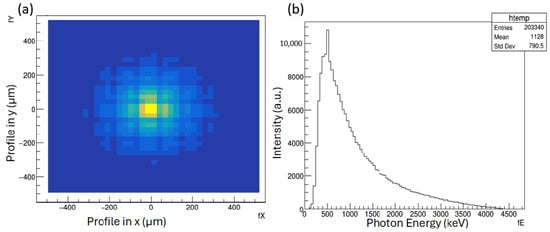
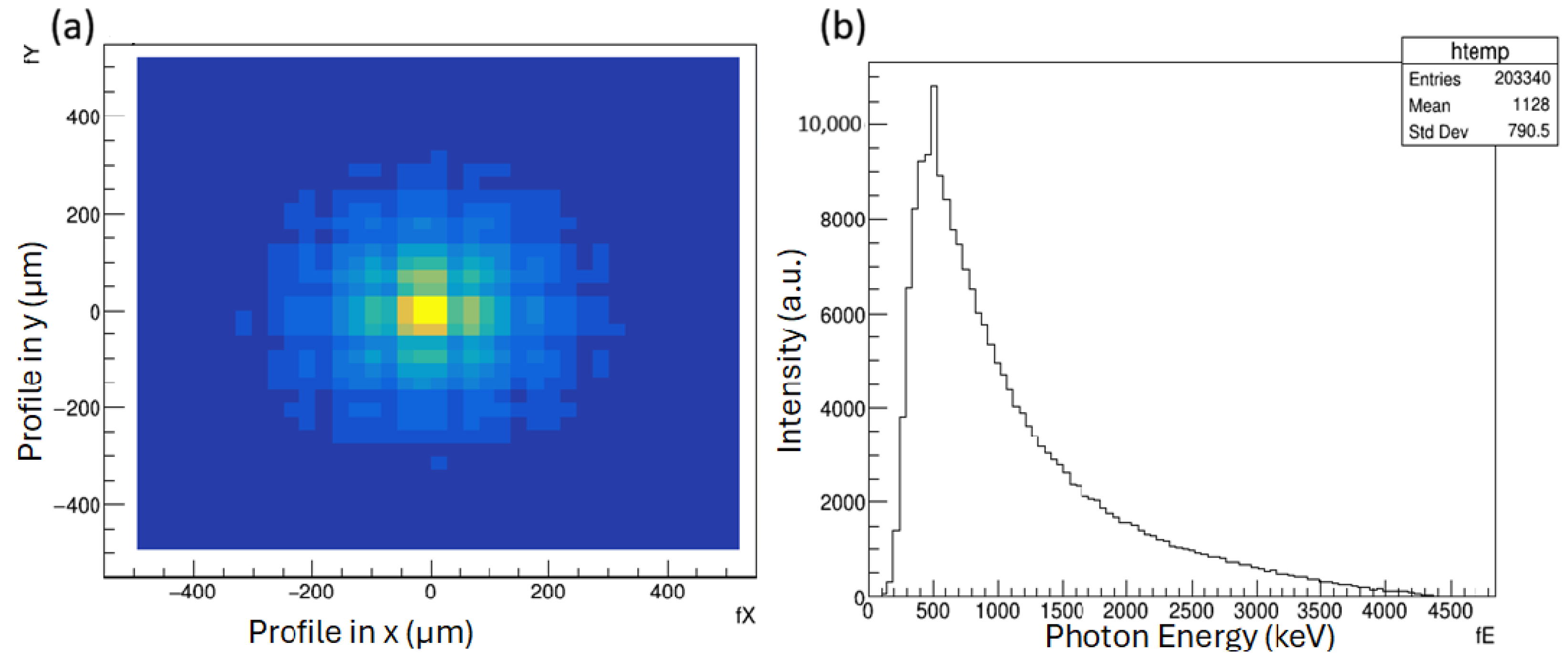
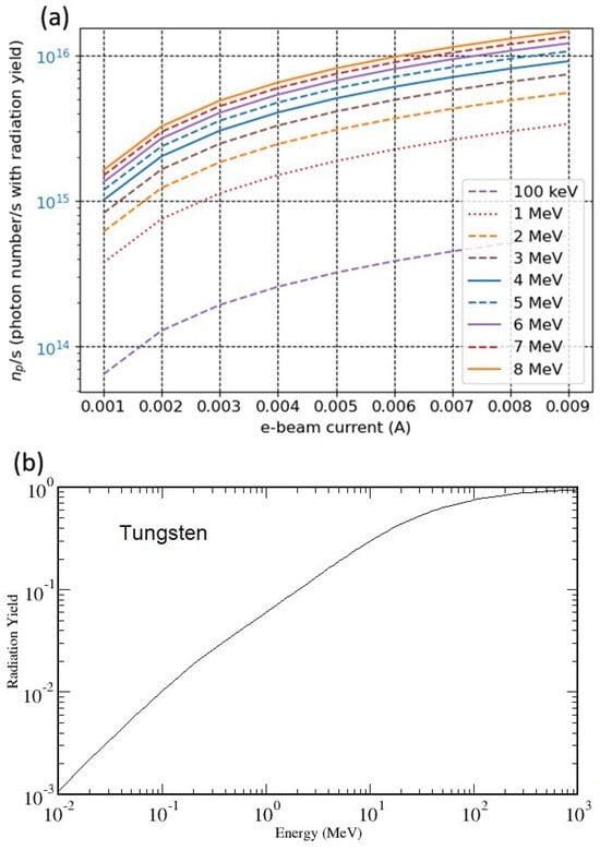
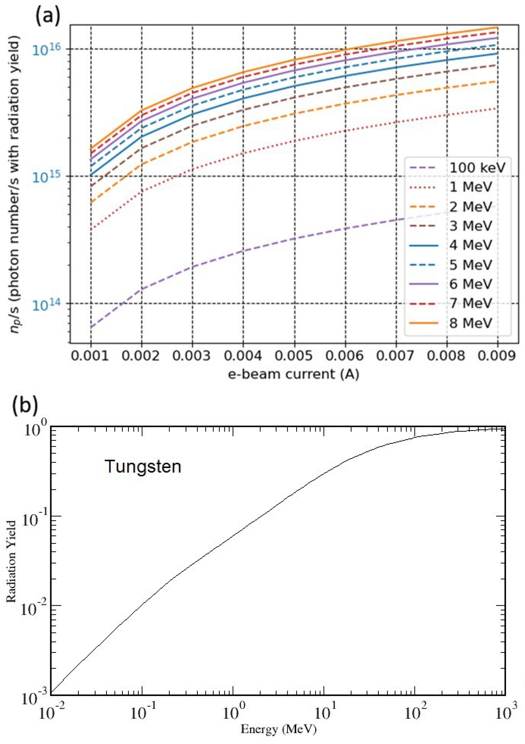
Over the past few decades, large accelerator facilities, known as “Big Science Machines,” have been built worldwide. Table 1 lists a selection. They are predominantly user-based national facilities supporting fundamental and applied research (from probing the building blocks of matter to enabling new particle discoveries), with GeV-scale beam energies, RF-cavity-based operation, and micro- to milliampere-level current; the beam is pulse-compressed to achieve high peak current at the target. However, small accelerators in the keV-to-MeV range are widely used for X-ray, -ray, and neutron production, from healthcare to space applications. Their acceleration techniques vary widely, from RF and induction methods to electrostatic schemes such as pyroelectric crystal accelerators, in which the crystal’s temperature-induced surface charge generates the accelerating field. Consequently, their configurations differ considerably. Their underlying applications mechanism, however, is often the same: a keV–MeV electron beam striking a target (such as tungsten or tantalum) generates bremsstrahlung photons. Figure 1 shows photon production from an electron beam, and Figure 2 shows that the beam power controls the photon flux [1]. By tuning the beam energy, a single electron accelerator can access the three principal photon–matter interaction regimes: photoelectric absorption, Compton scattering, and pair production.
Table 1.
Major particle accelerators ranked by length. Ring entries give circumference.
Figure 1.
A 5 MeV electron beam is incident on a 2 mm thick tungsten target in a Geant4 [2] simulation to generate radiation. (a) shows the radiation spectrum, and (b) shows the photon energy profile. The energy profile indicates that pair production occurs [3], with the energy balance given by , where and are the kinetic energies of the positron and electron, respectively; is the electron rest mass; and c is the speed of light. Above the pair-production threshold MeV, a peak appears at 511 keV, corresponding to positron–electron annihilation radiation.
Figure 2.
(a) The radiated photon number is calculated by multiplying the number of electrons (in the beam current) that are hitting the target by the radiation yield of the material (tungsten) for a given electron beam energy. In this case, Tungsten was used, and as shown in (b), the radiation yield was obtained from the database ESTAR (Electron Stopping Power and Range Tables, maintained by the National Institute of Standards and Technology (NIST), providing tabulated collision and radiative stopping powers and CSDA ranges for electrons in materials) [4].
Nowadays, a small accelerator is broadly defined as a compact electron or proton accelerator delivering few-keV to tens-of-MeV beams, distinguished from large-scale “Big Science" machines not by a single criterion such as transportability but by a combination of factors: reduced footprint, lower infrastructure demands, reduced shielding requirements, and suitability for installation and operation in applied environments such as hospitals, industrial facilities, security checkpoints, and laboratories [5,6,7,8]. Within this broader category, portable (hand-held) and transportable (vehicle- or satellite-based) systems—collectively referred to here as deployable—constitute an important sub-set for field applications. This definition encompasses a wide range of systems, from gram-scale pyroelectric crystal devices and hand-carriable electrostatic units to room-sized RF linacs, Rhodotrons, and conduction-cooled SRF modules.
At present, developments in MeV-range laser-wakefield accelerators (LWFAs) remain too far from practical application to fall within the scope of this review, while GeV-scale LWFAs are treated separately as a distinct “Big Science” direction [9,10,11,12].
The characteristic accelerating field of an LWFA follows from the cold (nonrelativistic) wavebreaking limit [9]:
where , , c, and e are the plasma frequency, the electron mass, the speed of light, and the electron charge, respectively. For a typical plasma density of , this gives —roughly three to four orders of magnitude larger than the accelerating gradient available in conventional RF accelerators. The LWFA [10,11] is a recent development with great potential to further advance “Big Science”.
In this article, we briefly review the accelerating mechanisms of traditional, small accelerators and show how they can be adapted to specific designs and applications. Several promising applications are highlighted in the subsequent sections.
2. Accelerating Mechanisms
In this section, we briefly review the accelerating mechanisms of ten compact accelerator types covered in this work: RF linacs, betatrons, Rhodotrons, permanent-magnet and DWA systems, pyroelectric and electrostatic accelerators, compact SRF modules, RFQs, and compact proton cyclotrons. Each system is discussed in terms of its underlying acceleration mechanism, key operating parameters, and characteristic applications, with a summary of distinguishing features presented in Table 2.
Table 2.
Key parameters of compact accelerator types reviewed in this work.
2.1. Basic Principle of Acceleration
Let us review the almost 100-year-old acceleration technique. All accelerators convert electromagnetic energy into the kinetic energy of charged particles. A moving charged particle experiences the Lorentz force (F) with particle charge (q), electric field (E), magnetic field (B) and velocity (v),
By the work–energy theorem, the change in kinetic energy, , equals the work done along the particle’s path,
where is an infinitesimal displacement along the path and the dot product retains only the force component along the motion, summed over the full path. The magnetic force is perpendicular to the velocity () and hence to , so it does no work and only steers and focuses the beam. Only the electric field accelerates the particle, giving kinetic energy
where V is the accelerating voltage traversed by the particle. In the simplest case, this voltage appears across a gap between two electrodes, and a particle crossing the gap gains energy ; for a uniform field across a gap of width d, , and . Accelerator types differ only in how this gap and its field are produced: a static high voltage in electrostatic machines or oscillating fields in resonant cavities in RF machines.
In an RF cavity the same picture applies, but the field oscillates in time. The axial field varies as , so a particle gains energy only if it crosses the gap while the field points in the accelerating direction. The energy gain per gap is then
where is the peak gap voltage and is the field’s phase when the particle arrives. The factor accounts for the field oscillating while the particle crosses the gap, so it does not see the full peak voltage; this is the transit-time factor. Because the field reverses every half-cycle, the particle must arrive at each gap in step with the RF. This synchronization is also the source of the RF machine’s chief advantage: instead of relying on a single large static voltage, which is capped by electrical breakdown, RF machines apply a moderate voltage repeatedly, at successive gaps along a linac or once per turn in a circular machine, so the beam accumulates energy gap by gap. These devices can be linear (linac), circular, or electrostatic; they have been well characterized over the years.
2.2. RF-Cavity-Based Linacs
The RF linac is among the most popular devices for both short and long systems, because the breakdown threshold is higher for pulsed RF fields than for static electrostatic electrodes, and thus has higher accelerator gradient (V/m). The maximum surface field sustainable in a room-temperature copper cavity is set by the Kilpatrick criterion, an empirical relation from vacuum-breakdown experiments over a wide range of frequencies and geometries [13]. In the form standardized by Boyd [14] and used in linac design [15], the breakdown field and the RF frequency f are related by
where is the Kilpatrick surface field in MV/m and f is the frequency in MHz. Solving Equation (6) gives MV/m at the L-band (1.3 GHz), ≈46 MV/m at the S-band (2.856 GHz), ≈63 MV/m at the C-band (5.712 GHz), and ≈88 MV/m at the X-band (11.424 GHz). The peak surface field exceeds the mean axial gradient by a factor , with for electron linacs and 4–5 for proton drift-tube structures [15].
Modern surface preparation techniques—such as electropolishing and high-pressure water rinsing—have been shown to raise the effective breakdown threshold well above the original Kilpatrick prediction, by a factor of two to three for CW operation and five to six for short RF pulses, provided that operation is sustained under ultra-high-vacuum (UHV) and clean-electrode conditions, limiting field emission and contaminant-driven breakdown [16,17]. This higher achievable threshold underlies the bravery factors used in practical structure design. Structures are therefore designed with a bravery factor of –2 for CW machines and up to ≈5 for pulsed high-gradient linacs. Because the RF wall power per unit length scales as , where the prime denotes a per-unit-length quantity and r is the shunt impedance per unit length, a figure of merit quantifying the accelerating gradient achieved per unit of dissipated wall power [15], the breakdown ceiling of Equation (6) bounds the accelerating gradient and the energy gain per unit length. Through beam loading, i.e., the partial cancellation of the accelerating field by the beam-induced voltage, the maximum beam current and average beam power are also limited whenever the available RF power from the source (klystron or solid-state amplifier) or the input coupler bandwidth becomes the binding constraint [15].
An RF accelerator’s performance depends on cavity parameters such as the cell length ( for -mode structures, and for an Alvarez drift-tube linac operating in the mode, where is the particle velocity relative to the speed of light and is the RF wavelength). Here, - and 0-mode structures are distinguished by the phase change experienced by a synchronous particle as it travels from one accelerating gap to the next: radians for -mode structures and zero for 0-mode (Alvarez-type) structures. The Alvarez drift-tube linac (DTL) is an early type of linear accelerator originally used to accelerate protons and ions at low-to-medium energies. It consists of a single, long resonant cavity containing a series of metal “drift tubes” of increasing length, each shielding the particle from the electric field while it is decelerating so that the particle is accelerated only when crossing the gaps between tubes; the tube lengths grow along the structure to keep the particle synchronized with the RF field as it gains speed. Newer compact structures are now generally preferred, as they operate more efficiently at low energies. The Alvarez DTL is mentioned here only as historical background for compact proton linac development, not as a structure used in current deployable systems. The gap field is defined as , where is the field-amplitude distribution and , t, and are the angular frequency, time, and RF phase. The synchronous particle’s energy gain per gap is [18,19]
where q is the charge, is the average axial field, is the gap voltage, T is the transit-time factor, and is the synchronous phase; further details appear in standard texts and USPAS notes [20]. SLAC, Fermilab, and LANSCE are large-scale examples. Many compact S-, C-, and X-band accelerators reach much higher gradients in far shorter lengths [21,22], with some being used for radiotherapy and security with dose rates of order R/min at 1 m [23,24]. Meter-long S-band (2.856 GHz) or C-band (5.712 GHz) structures reach 20–50 MV/m, producing 1–10 MeV electron beams [6,8]; modern X-band (∼12 GHz) units exceed 100 MV/m [21,22], shrinking the structure further. Mobile cargo inspection and portable industrial radiography now rely largely on this technology [6]. Compact electron accelerators also serve diagnostic and scientific uses: non-destructive profile measurements [25] of high-energy charged-particle beams; space experiments and instrument calibration for electron and proton flux studies in the Van Allen belts [26]; and calibration of beam-loss monitors.
2.3. Betatrons
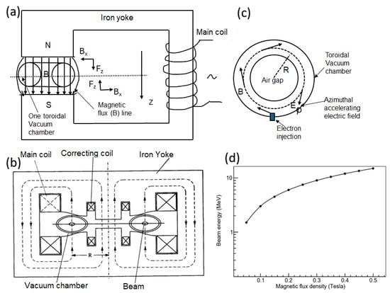
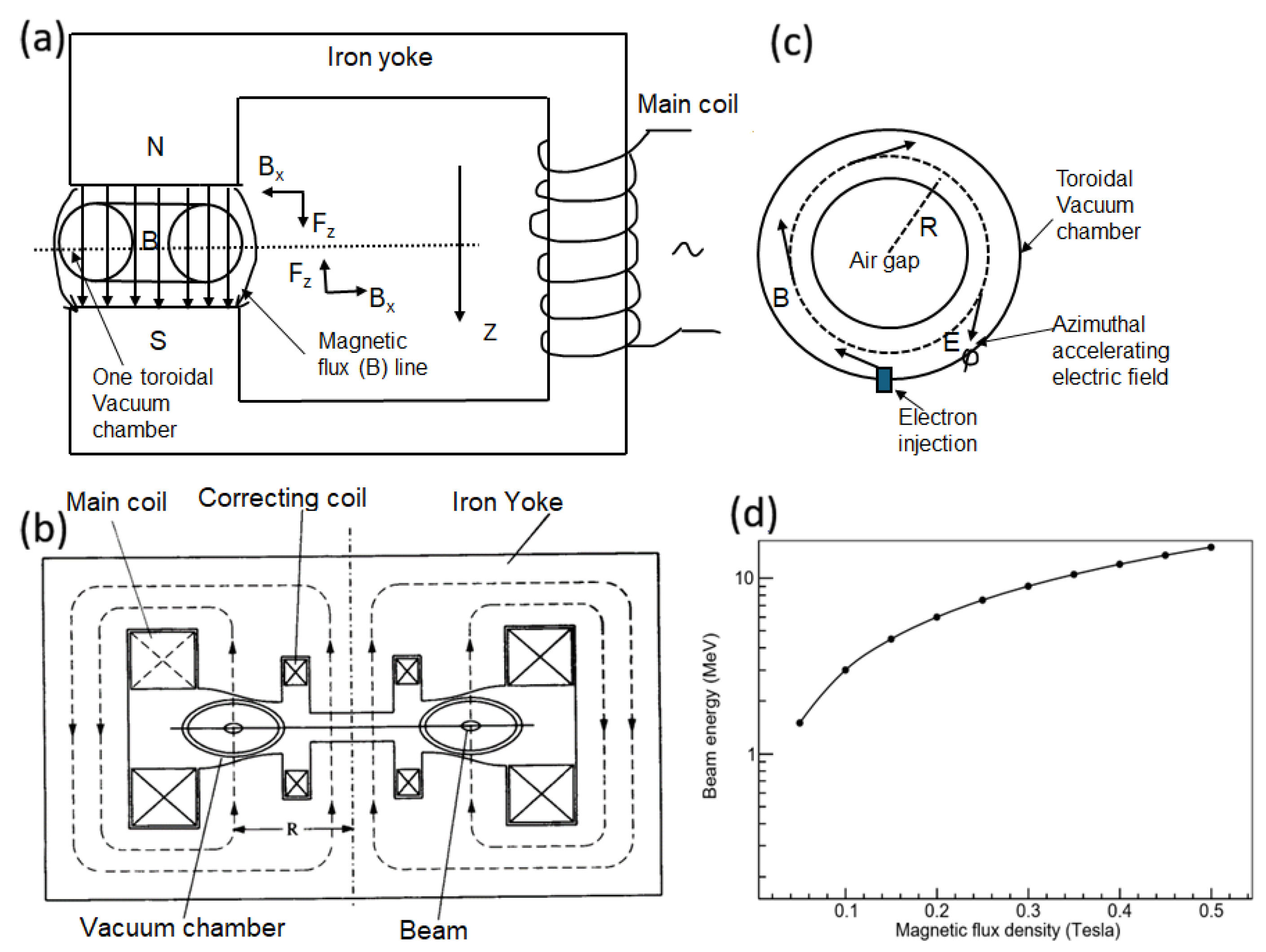
Betatrons are well suited to radiographic imaging, material studies, and industrial inspection. A betatron [27,28,29,30,31,32] is an induction accelerator that uses a time-varying magnetic flux to accelerate electrons on a circular orbit. Electrons are injected from an internal thermionic gun at tens of keV into the ring (orbit radii of a few centimeters to about half a meter) for recirculation and acceleration. Figure 3a shows a coil, driven by a 50–60 Hz sinusoidal voltage, embedded in a ferromagnetic core to generate magnetic flux . The changing flux () produces an azimuthal electric field that accelerates electrons orbiting in a toroidal vacuum chamber, while the vertical flux density B confines them to a circular orbit.
Figure 3.
(a) A coil embedded in a ferromagnetic core to generate magnetic flux; (b) a nominal betatron configuration; (c) a toroidal vacuum chamber with orbit radius R; (d) applied flux density vs. beam energy for a 5 cm orbit, using the conservative envelope ; the actual energy lies below this curve (see text).
The accelerating field follows from Faraday’s law in integral form,
Stable acceleration at constant radius requires the betatron (Widerøe) condition, , where is the average flux density within the orbit and is the field at the orbit. The electron momentum is then
where R is the orbital radius; for relativistic electrons, the beam energy is ≈pc. For a 5 cm orbit with T, Equation (9) gives MeV (kinetic energy MeV). Figure 3d plots against beam energy using the conservative envelope , four times Equation (9); the achievable energy lies well below it.
The betatron needs only a single pulse modulator: the circuit is a single primary winding, with the circulating electrons as multiturn secondary windings. The average accelerating gradient is therefore not a primary concern, and low voltages with long pulse lengths are used. The magnet is driven by a bipolar sinusoidal waveform that cycles the core between and . The toroidal tube’s wall resistance must be high enough to keep the inductive return current small. For lower-energy operation, the coil, core, and beam-tube dimensions are reduced, lowering mass and footprint. The vacuum chamber has traditionally been made of glass, quartz, or ceramic by specialist glass blowing. Recent supply-chain disruptions for such tubes have prompted manufacturers to explore alternative materials or to replace the betatron with a C-band linac, though some suppliers have since restored production. Betatron X-rays are widely used in industrial non-destructive testing (NDT): inspecting large forgings, castings, pressure vessels, and thick welds, as well as cargo security screening. Because small betatrons are portable, variable-energy units may also be used in field applications such as soil composition and density measurements in agriculture to detect fertilizer compositions and concentration.
2.4. Rhodotron
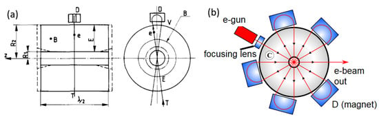
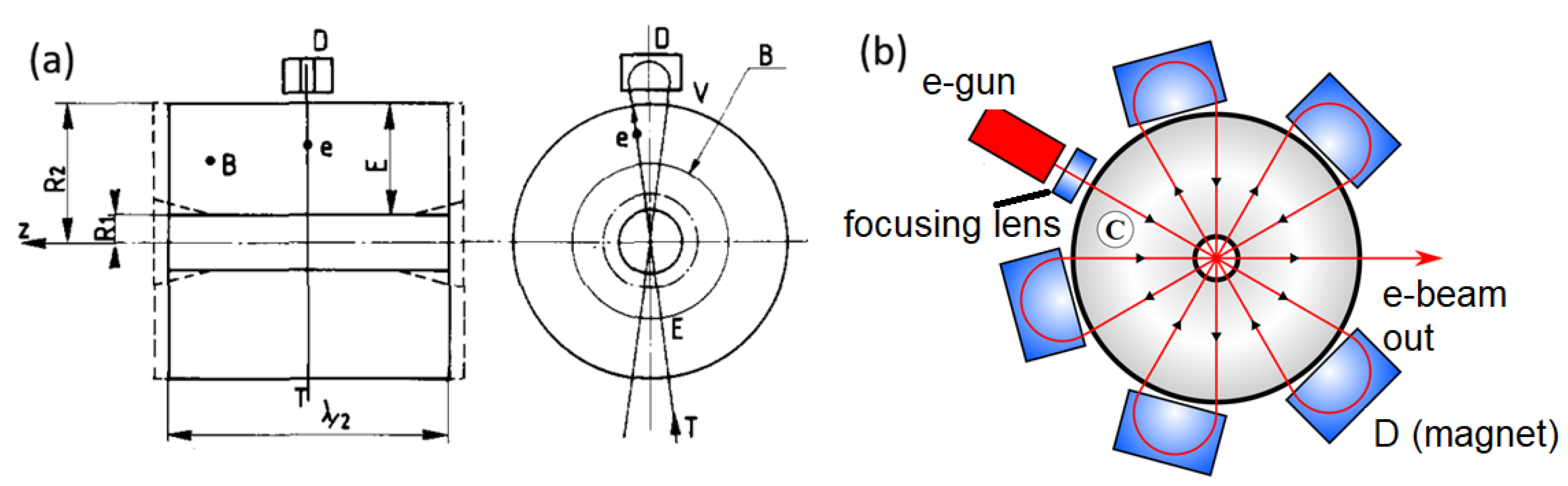
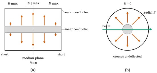
The Rhodotron [33,34] is a recirculating coaxial-cavity electron accelerator in which the beam traverses a single RF cavity many times, following a rosette-shaped trajectory in the median plane to reach 1–10 MeV [33]. The cavity operates in a coaxial (TEM) mode with a radial electric field. As shown by Pottier [33], in a resonator formed from a half-wavelength () coaxial line shorted at both ends, the magnetic field vanishes in the median plane, where the field is purely radial, so the beam crosses along a diameter without deflection. In this plane the radial field is [15]
where a and b are the inner and outer conductor radii, is the peak voltage between them, and and are the RF angular frequency and phase. An electron crossing the full diameter is accelerated twice: once moving inward toward the inner conductor and again moving outward on the opposite side, with the second acceleration being possible because the field reverses while the electron passes the central region [33]. Combining this field with the standard RF-gap energy gain [18,19], the energy gain per crossing is
where q is the electron charge, T is the effective transit-time factor over the radial path, and is the synchronous phase; the factor of two accounts for the two accelerating gaps per crossing. After n crossings, the beam energy is . Because wall losses are incurred once while the energy gain scales with n, the effective shunt impedance rises as [33], the origin of the Rhodotron’s high power efficiency.
Between crossings, external bending magnets turn the beam around and return it for the next pass. The return geometry is fixed: each orbit spans one RF wavelength in path length, so the beam, already relativistic after the first crossing (), always re-enters in phase. The bending radius is therefore the same for every magnet. Since the beam gains energy at each crossing, the magnets cannot share a common field; to hold fixed while bending a higher-momentum beam through the required angle, the magnet for the n-th return must satisfy the rigidity condition
where is the beam momentum after n crossings. The field therefore increases from pass to pass, scaling with momentum (and, for relativistic electrons, with energy), so the final pass demands the strongest field.
Figure 4 shows the Rhodotron concept.
Figure 4.
(a) The Rhodotron concept [33], where B, , D, and E denote the magnetic field (zero in the median plane), the electron trajectory, the deflecting magnetic field, and the electric field, respectively; (b) an artistic view [34] of the Rhodotron [33].
The copper-plated steel cavity resonates at ∼107.5 MHz and provides about 1 MeV per crossing. Typically, 7–12 passes yield 5–10 MeV beams at powers of up to ∼700 kW [6].
Both panels of Figure 5 show the same cavity cut two ways. Its coaxial geometry (a central conductor within an outer conductor) gives a cable-like appearance in (a), but it is a closed resonant chamber shorted at both ends, not a signal-carrying cable: Pottier’s “ coaxial line” refers to a short, wide coaxial section closed at both ends to form a resonator.
Figure 5.
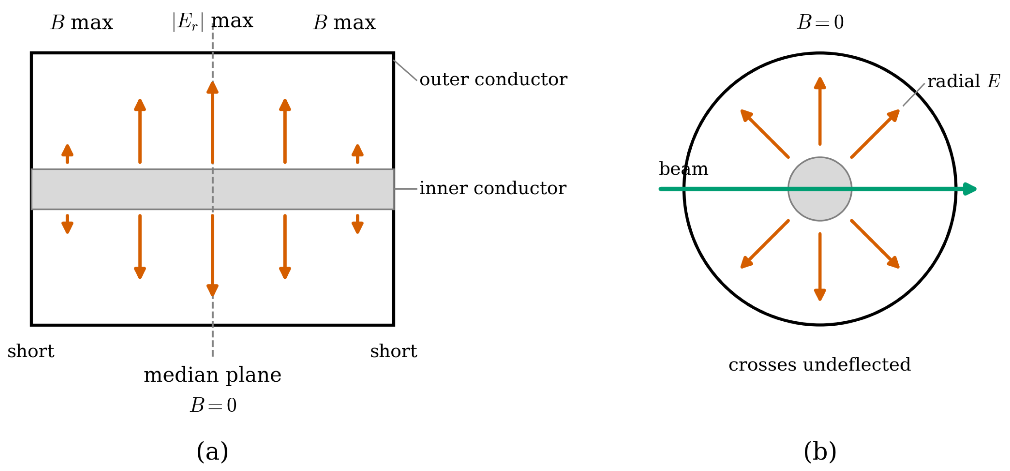
Two cross-sections of the same coaxial resonant cavity of the Rhodotron, derived from a half-wavelength () coaxial line short-circuited at both ends. (a) Axial section (a cut through the coaxial axis), showing the inner conductor, the outer conductor (cavity wall), and the shorting plates at each end. The radial electric field forms a standing wave that is maximal at the median plane and vanishes at the shorted ends, while the azimuthal magnetic field B is zero at the median plane and maximal at the ends; arrow lengths indicate the field magnitude. (b) Transverse section at the median plane (a cut perpendicular to the axis), obtained by slicing (a) along the dashed line. Here the field is purely radial and , so the electron beam can cross the cavity along a diameter without being deflected.
Although high-power versions occupy a room-sized footprint, the Rhodotron was developed mainly for industrial use [35] such as medical-device sterilization, food irradiation, and X-ray inspection [8].
2.5. Permanent-Magnet and Dielectric-Wall Accelerators (DWAs)
2.5.1. Permanent-Magnet Accelerators
Permanent-magnet quadrupoles (PMQs) are used as focusing elements in compact proton linacs, cyclotron-to-gantry transport lines, and laser–plasma accelerator beamlines, where their high field gradients (>100 T/m in millimeter-bore devices), zero power consumption, and small footprint make them attractive alternatives to electromagnetic quadrupoles [36]. In a compact proton therapy linac, for example, a FODO lattice of PMQs provides the transverse focusing required to transport a low-emittance beam from the RFQ through the main linac to the patient [37]. Conventional accelerators use electromagnets to focus and bend the beam. These require substantial space around the beam line and electrical power, with resistive losses dissipated as heat. Replacing them with rare-earth permanent magnets—neodymium–iron–boron (NdFeB) or samarium–cobalt (SmCo)—removes the power supplies and cooling systems, reducing footprint and operating cost. In a Halbach array, the magnetization direction rotates spatially through the assembly [36], concentrating flux within the bore to produce strong transverse focusing fields while nearly canceling the external fringe field. This makes them well suited to compact quadrupole focusing channels in proton linacs and cyclotrons [38].
The key parameter is the remanent field , the flux density retained when the external magnetizing field is removed (where the hysteresis loop crosses the B-axis). At room temperature, reaches ∼1.2–1.45 T for NdFeB and ∼0.9–1.1 T for SmCo. For an ideal Halbach quadrupole of bore radius and outer radius , the field gradient G scales as [36]
Because G rises as the bore shrinks, high gradients are readily reached in millimeter-bore devices, enabling the strong focusing of low-emittance proton beams at therapy energies (70–250 MeV) [37].
Two challenges arise. First, NdFeB has a remanence temperature coefficient of about K−1, so a 10 K rise lowers by ∼1.2%, shifting the beam-optics tune and possibly requiring active thermal stabilization. SmCo, with a smaller coefficient (∼ K−1), is preferred in thermally demanding environments. Second, radiation hardness under prolonged beam exposure is a concern: NdFeB shows measurable demagnetization at fast-neutron fluences above ∼ n/cm2 and substantial loss by ∼ n/cm2 [38], whereas SmCo and certain ceramic ferrites tolerate radiation considerably better and are favored in high-radiation sections. Permanent-magnet systems are therefore useful where the power budget for focusing is limited, though the magnet mass remains considerable.
2.5.2. Dielectric-Wall Accelerators (DWAs)
A dielectric-wall accelerator (DWA) is a compact linear accelerator whose accelerating structure is a stack of alternating high-gradient insulator (HGI) and conducting layers [39]. The finely laminated HGI suppresses vacuum surface flashover by interrupting the secondary-electron avalanche that would otherwise develop along the insulator wall, letting the structure sustain fields above the practical limit of conventional copper RF structures [39].
Acceleration is driven by fast high-voltage pulses (rise time ∼1–10 ns); the resulting flat-top longitudinal field travels along the structure at the bunch velocity, maintaining synchronism and continuous energy transfer. The kinetic energy gain per unit length is
where q is the particle charge and is the synchronous phase, the bunch’s timing offset relative to the field crest. For a velocity-matched flat-top pulse, the bunch ideally rides at and samples the full gradient, ; timing errors reduce the gain by .
High gradient with a compact footprint makes the DWA attractive for proton therapy: in principle the full 70–250 MeV therapeutic range could be reached in a structure ∼2–3 m long. The DWA, while targeting proton therapy energies, is included here as an emerging compact proton acceleration concept under active development.
2.6. Pyroelectric and Electrostatic Accelerators
The pyroelectric scheme is an electrostatic method whose high voltage comes from the crystal’s surface charge rather than an external supply. When a pyroelectric crystal (e.g., LiNbO3 or LiTaO3) is heated or cooled, its spontaneous polarization changes, leaving uncompensated charge on the surface. This produces a strong local field that accelerates charged particles: electrons onto a target for bremsstrahlung X-rays or deuterons to energies high enough to drive D–D fusion and neutron production. These energies are at the keV scale (tens to a few hundred keV), the low end of the keV–MeV range. Pyroelectric and compact electrostatic accelerators offer unique capabilities where size, mass, and power are severely constrained.
2.6.1. Pyroelectric Crystal Accelerators
Pyroelectric materials such as lithium niobate (LiNbO3) and lithium tantalate (LiTaO3) possess a spontaneous polarization that varies strongly with temperature. Heating or cooling therefore changes the bound surface-charge density and, if unscreened, produces a large transient field. For a temperature excursion , the change in surface-charge density is
where the pyroelectric coefficient . At room temperature for LiNbO3 and for LiTaO3 [40]. In vacuum, under ideal unscreened open-circuit conditions, the potential across a crystal of thickness d and polar-axis permittivity follows from zero net free charge, , giving
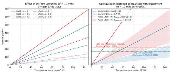
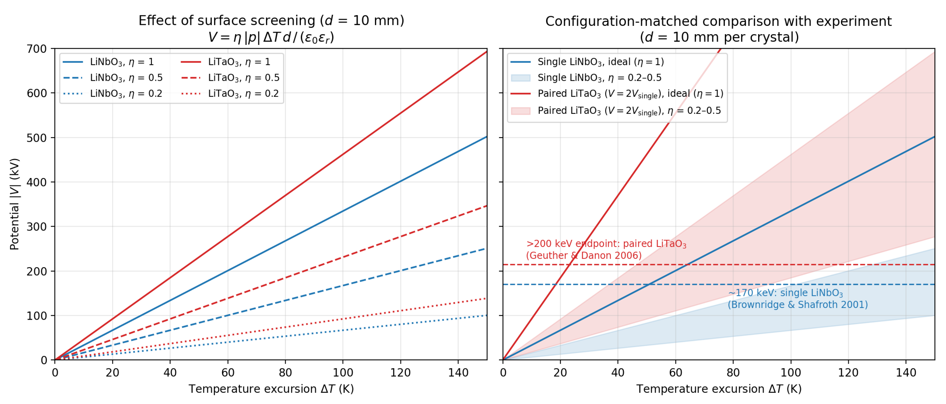
with for LiNbO3. This yields 10–100 kV across millimeter-scale crystals for swings of –100 K, though surface screening by free charges partially reduces the achievable voltage in practice [40,41]. Figure 6 shows the potential from Equation (16) versus for both crystals. The left panel shows how surface screening, modeled by an efficiency , suppresses the ideal open-circuit potential; the right panel compares the model with demonstrated single- and paired-crystal endpoint energies [42,43]. For a representative K cycle, the benchmarks imply –, consistent with substantial but incomplete screening.
Figure 6.
Pyroelectric open-circuit potential versus temperature excursion , computed from the open-circuit relation for crystals of thickness mm along the polar axis, using room-temperature material constants [40]: C m−2 K−1 and for LiNbO3, and C m−2 K−1 and for LiTaO3. The factor represents the fraction of pyroelectric surface charge unscreened by free carriers. (Left): Single-crystal potential for both materials in the ideal unscreened limit (, solid) and under moderate (, dashed) and heavy (, dotted) screening. Despite its larger pyroelectric coefficient, LiTaO3 exceeds LiNbO3 by only a factor of ∼1.4 in voltage per kelvin owing to its higher permittivity. (Right): Configuration-matched comparison with experiment. The single-LiNbO3 curve (blue) is compared with the ∼170 keV electron energies observed from a single crystal [42] and the paired-LiTaO3 curve (red), for which the ideally phased potential is , with the >200 keV bremsstrahlung endpoint demonstrated using two opposing crystals [43]; shaded bands span –. For a representative K cycle, the benchmarks imply screening efficiency of (single crystal) and (paired), with the latter reflecting the difficulty of phasing the two thermal cycles. Endpoint energies equal only when emission coincides with the peak potential; the temperature dependence of p and and the dynamics of charge screening are neglected, so all curves are order-of-magnitude estimates.
A sharp tungsten tip on the crystal face locally enhances the field enough to drive electron field emission; the electrons are then accelerated across the crystal potential. Single-crystal systems produce electron beams up to ∼170 keV at nA–A currents, enough to generate bremsstrahlung X-rays and excite characteristic fluorescence [42]. Two opposing crystals cycled out of phase can nearly double the potential under ideal phasing, and X-ray endpoints above 200 keV have been demonstrated [43].
The complete system (crystal, resistive heater or Peltier element, tip, and target) fits within 10–100 cm3 at a mass of a few tens of grams, drawing only milliwatts to watts of thermal drive power depending on the cycling rate. This compactness has motivated pyroelectric X-ray fluorescence (XRF) sources for planetary surface science, where radioisotope sources and high-voltage supplies are impractical; such generators have been studied for lunar and asteroid landers that characterize regolith composition in situ [44].
The principal limitations are interrelated. The average current is low because the duty cycle is set by the thermal cycling rate (∼0.01–0.1 Hz passive, up to ∼1 Hz with active Peltier control). The electron spectrum is broad chiefly because the potential is not constant: it ramps as the crystal heats or cools, so electrons are emitted across a range of instantaneous potentials, with inelastic collisions in residual gas broadening it further. Finally, performance is sensitive to residual pressure: above ∼ Torr, the emitted electrons ionize gas molecules, and the resulting positive ions back-bombard the tip, partially neutralizing the surface field and suppressing further emission [42].
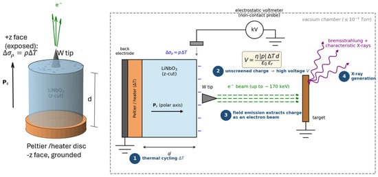
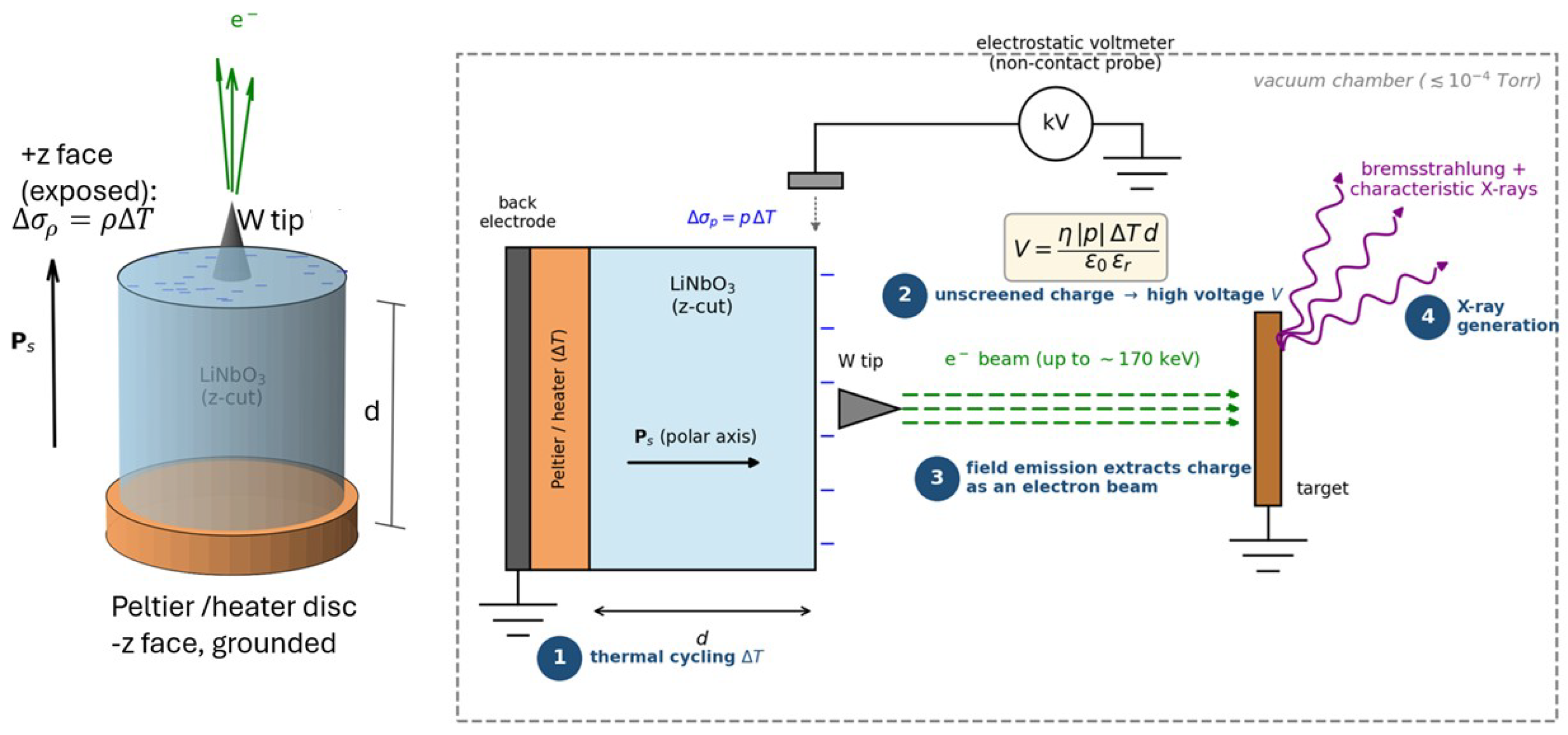
Figure 7 shows the device concept: the pyroelectric crystal element and a representative configuration in which the extracted electron beam generates X-rays.
Figure 7.
Conceptual layout of a pyroelectric crystal X-ray generator (heating phase shown; not to scale). (Left): The crystal element in 3D, a cylindrical z-cut LiNbO3 crystal of thickness d with its spontaneous polarization along the cylinder axis. The face is thermally anchored to a grounded Peltier/heater disc that drives the temperature excursion , while the exposed face carries the uncompensated surface charge ; a sharp tungsten tip at the face center provides the local field enhancement for electron emission. (Right): System schematic of the operating sequence: (1) thermal cycling, (2) generation of the high voltage [Equation (16) with screening efficiency ], monitored by a non-contact electrostatic voltmeter, (3) extraction of the surface charge as an electron beam by tip field emission, and (4) X-ray production (bremsstrahlung and characteristic lines) at a grounded target. The polarity shown corresponds to heating () and reverses on cooling; operation requires residual pressures below ∼ Torr to avoid ion back-bombardment of the tip [42].
2.6.2. Electrostatic Accelerators: From Large Facilities to Compact Designs
Electrostatic accelerators use a static high-voltage terminal to accelerate ions or electrons directly. The Cockcroft–Walton (CW) voltage multiplier [45] supplied the voltage for the first artificial nuclear disintegration in 1932 and later served as the injector in many facilities, such as Los Alamos (LAMPF/LANSCE). Van de Graaff and Pelletron machines, which use mechanical (belt or chain) charging, reach higher voltages: large tandems at national laboratories (e.g., Sandia, LANL, and LLNL) operate up to ∼25 MV and some laboratory phase tandems at 0.5–5 MV [46].
The largest machines are not portable, but their principles carry over to compact accelerators. Electrostatic machines deliver stable, high-resolution DC beams at MeV energies, and lower-voltage single-ended designs can be made compact and transportable. With modern high-voltage supplies and solid-state electronics, these principles can be adapted to small, hand-carriable units. Their operating physics is presented below.
In a Cockcroft–Walton (CW) multiplier, a cascade of n diode–capacitor stages rectifies an AC input of peak voltage into a high DC output. The ideal no-load output is . Under load, the mean output is lowered by a regulation drop, and a ripple is superimposed on it [47]:
where I is the load current, f is the AC frequency, C is the stage capacitance, and is the peak-to-peak ripple. Both the drop and the ripple grow rapidly with the number of stages n. Raising f into the MHz range allows C—and hence the physical stage size—to be reduced sharply, which is what makes high-frequency CW stacks small enough to be portable. Such stacks serve both as injector stages for larger accelerators and as standalone ion sources for neutron generators. Two reactions are commonly exploited: the D–D reaction 2HHe, driven at 80–300 keV deuteron energies to produce 2.45 MeV neutrons, and the D–T reaction 3HHe, driven at 80–200 keV to produce 14.1 MeV neutrons.
Van de Graaff and Pelletron accelerators transport charge mechanically—on a moving belt or chain—to a high-voltage terminal, reaching 1–20 MV in large research machines and 0.5–5 MV in compact tandems [46]. In a tandem, negative ions injected at ground potential are accelerated toward the positive terminal, stripped to a charge state by a thin foil or gas, and re-accelerated back to ground, giving a kinetic energy
where is the terminal voltage and the small injection energy is neglected [46]. A tandem thus delivers at least twice the energy of a single-ended machine at the same terminal voltage—and more for multiply stripped ions—without enlarging the pressure vessel. Compact tandems fit within a single laboratory room and are used for accelerator mass spectrometry (AMS), ion-beam analysis (IBA), and materials modification with MeV-range light ions [48].
The practical voltage limit is set by electrical breakdown of the insulating medium—typically SF6 at 4–6 atm or solid insulators in miniaturized devices. The intrinsic dielectric strength of SF6 is kV/cm at 1 atm in a uniform field [49]; approaching it requires surface conditioning, field-grading electrodes, and corona control. The strength rises with pressure roughly as , with – depending on electrode geometry and gap length [49].
The Van de Graaff and Pelletron machines are used to accelerate ions and protons, not electrons, and the mechanical charging mechanism makes them impractical for electron acceleration to useful energies in compact configurations.
2.7. Compact Superconducting RF (SRF) Modules
Superconducting radiofrequency (SRF) technology underpins the world’s highest-performance large-scale accelerators, but its reliance on liquid-helium bath cryogenics—liquefaction plants, pressurized distribution lines, and gas-recovery systems—has historically confined it to major facilities. Two recent advances remove this barrier: mature Nb3Sn cavity coatings and cryocooler conduction cooling.
2.7.1. Nb3Sn Cavities and Cryocooler Conduction Cooling
Niobium–tin (Nb3Sn) [50] is a Type-II superconductor with a critical temperature K, about double the K of bulk niobium. This higher lets Nb3Sn-coated cavities operate at 4.2 K with intrinsic quality factors – at low to moderate gradients—performance that niobium cavities reach only at 2 K. At 4.2 K the RF wall losses fall within the reach of commercial closed-cycle pulse-tube cryocoolers (e.g., the Cryomech PT420, rated at ∼2 W at 4.2 K), eliminating liquid helium altogether [50].
In conduction cooling, high-purity (5N) aluminum links couple the cavity to the cold head of one or more 4 K cryocoolers, which extract the RF dissipation and hold the cavity superconducting without any circulating cryogen. The approach was first demonstrated at Fermilab on a single-cell 650 MHz Nb3Sn-coated niobium cavity [51]. Because a cryocooler’s cooling capacity increases with temperature, operating the cavity warmer—at ∼7.2 K rather than ∼4.4 K, where more cooling is available—raised the cw accelerating gradient to 6.6 MV/m, all within a simple vacuum vessel free of liquid helium [51].
2.7.2. Modular 10 MeV Class Electron Accelerators
Building on this demonstration, Fermilab designed a full accelerator module around a five-cell 650 MHz Nb3Sn-coated niobium cavity conductively coupled to eight 4 K pulse-tube cryocoolers: six Cryomech PT420 (2.0 W at 4.2 K) cooling the cavity body and two PT425 (2.5 W at 4.2 K) over the RF couplers [52]. The cryomodule is about 1.95 m long end to end and targets a 10 MeV, 100 mA beam—1 MW of average power—fed by two fundamental power couplers rated for 500 kW cw each, with a design RF-to-beam efficiency above 90% that has yet to be demonstrated at full power. The intended application is high-volume industrial wastewater treatment, processing up to 12 million gallons per day [52]. Because each module carries its own cavity, cryocoolers, couplers, and vacuum vessel, the system scales to higher energy or power by adding self-contained modules, without the centralized helium plant that bath-cooled SRF requires [52].
This cw, high-average-power operation rests on the low surface resistance of Nb3Sn, conventionally split into a temperature-dependent BCS term and a residual term [50],
scales as and falls as , with a superconducting gap meV (the weak-coupling value of ; strong coupling gives somewhat more). With a residual term of ∼10 n, practical Nb3Sn cavities reach –20 n at 4.2 K and 650 MHz—about an order of magnitude below niobium at the same temperature and frequency (∼200 n), and roughly a factor of 50 lower at 1.3 GHz [50].
By removing liquid-helium infrastructure, conduction cooling lowers the cost, footprint, and operational complexity of small-to-medium SRF accelerators and enables turn-key deployment outside the laboratory. Candidate applications for 10 MeV class cw SRF electron accelerators include wastewater and sewage-sludge treatment, flue-gas desulfurization, polymer cross-linking, sterilization, and food processing, as well as high-power X-ray and photoneutron sources for cargo inspection [51,52].
2.8. RFQ Accelerators
The radio-frequency quadrupole (RFQ) is the standard first-stage accelerator for protons and light ions, simultaneously providing bunching, focusing, and acceleration from the ion source energy (∼10–100 keV) to the injection energy of the downstream linac (∼1–10 MeV) within a compact structure of 1–3 m [53,54]. An RFQ consists of four electrodes (vanes or rods) arranged around the beam axis with a time-varying RF potential applied between adjacent electrodes. Unlike conventional linac structures, the RFQ achieves focusing and acceleration using a single RF field, through electrode surfaces modulated periodically along z. The electric potential near the axis is commonly approximated as [15,53]
where is the electric potential near the beam axis, r and are the radial and azimuthal coordinates measured from the beam axis, z is the longitudinal coordinate along the beam direction, is the peak RF voltage applied between adjacent electrodes, is the average aperture radius, A is the acceleration efficiency parameter, , is the synchronous particle velocity relative to c, is the RF wavelength, and is the modified Bessel function of order zero, which describes the radial dependence of the accelerating field component. The first term produces the transverse quadrupole focusing gradient, while the second term, generated by the longitudinal modulation of the electrode radius, provides the axial electric field responsible for bunching and acceleration.
The degree of modulation is characterized by the modulation parameter
where a is the minimum aperture radius at a given cell and is the unmodulated radius; m typically increases smoothly from unity (, pure focusing, no acceleration) in the initial radial-matching section to – in the main accelerating section, allowing the RFQ to adiabatically capture a continuous or weakly bunched beam from the ion source and compress it into RF buckets before it is significantly accelerated [53]. This adiabatic bunching is what allows the RFQ to achieve high capture efficiency, typically >90%, compared with conventional bunchers.
Unlike the Alvarez DTL, where each cell is a discrete drift tube, the RFQ is a single continuous resonant structure (not a series of separate cavities) divided into many short longitudinal segments called “cells,” each corresponding to one period of the electrode modulation. The energy gain per cell follows from the longitudinal field component, similar to Equation (7), giving the synchronous energy gain,
where q is the ion charge state, is the average axial accelerating field, T is the transit-time factor, is the synchronous phase, and L is the cell length, defined as the longitudinal distance corresponding to one period of the electrode modulation; for a synchronous particle, this length is related to the local particle velocity by , so that successive cells lengthen progressively along the RFQ as the beam is accelerated [15]. In the initial bunching section, is set close to (minimal acceleration, maximal bunching), then ramped toward more efficient values ( to ) through the accelerating section to balance longitudinal capture with acceleration efficiency.
Because the transverse focusing gradient scales with [Equation (21)], the RFQ provides strong, continuous transverse focusing along its full length even at the low velocities where space-charge defocusing is the most severe—a key advantage over drift-tube structures, which require external quadrupole focusing at these energies. This makes the RFQ particularly well suited as the first accelerating structure in compact proton and light-ion linacs.
Although protons and light ions are the most common species accelerated by RFQs, the underlying electric-focusing mechanism [Equation (21)] is not proton-specific: it depends only on the ion’s charge-to-mass ratio and velocity, not its identity. Consequently, RFQs are also widely used to accelerate H− ions, commonly chosen for synchrotron and storage-ring injection because charge-exchange (stripping) injection allows for higher circulating currents than direct proton injection, as well as deuterons for neutron-generator applications and heavier ions (e.g., He, C, and other species up to uranium) as the first accelerating stage in heavy-ion linac injectors. In each case, the RFQ design parameters—operating frequency, peak voltage , and vane modulation profile—must be re-optimized for the species-dependent charge-to-mass ratio, but the basic operating principle of simultaneous bunching, focusing, and acceleration remains unchanged.
Recent developments toward high-gradient RFQs suitable for compact proton therapy injectors and portable neutron generators are noted. Several realizations illustrate the RFQ’s role in compact accelerator systems. The BEAR RFQ [55] was flown aboard a sounding-rocket experiment to demonstrate compact ion acceleration in a launch environment. AccSys Technology developed an early transportable RFQ for on-site isotope production. Compact RFQ designs also serve as injectors for proton therapy linacs, where footprint and reliability are paramount. A more recent example is the 750 MHz compact RFQ used in several applications, including the transportable MACHINA system for in situ PIXE (particle-induced X-ray emission) analysis. Portable RFQ-based neutron generators represent a further application area, although much of this work remains unpublished.
2.9. Compact Proton Cyclotrons
Compact proton cyclotrons, including isochronous and superconducting designs (e.g., IBA Cyclone 230, Varian ProBeam, and Mevion S250), have achieved sufficient reduction in footprint and mass to be installed in single-room hospital-based proton therapy centers. These cyclotrons exemplify the broader trend toward increasingly compact, and in some cases transportable, accelerator systems.
In a cyclotron, protons circulate in a static magnetic field B and cross an RF-driven accelerating gap once or twice per revolution at the non-relativistic cyclotron frequency , gaining energy per turn
where q is the proton charge, n is the number of gap crossings per revolution, is the peak gap voltage, and is the RF phase at crossing; typically – turns are needed to reach therapy energies. Since falls with energy as the relativistic mass increases ( is the proton rest mass), isochronous cyclotrons shape the field to rise with radius, i.e., , where is a Lorentz factor, keeping the orbital frequency constant; the resulting radial defocusing is compensated by an azimuthally varying (hill–valley) field pattern that restores vertical focusing, the AVF (Azimuthally Varying Field) principle introduced by Thomas [56]. The maximum energy for given extraction radius and field with the velocity of light, c, is then
so that the higher fields achievable with superconducting magnets allow for the same extraction energy at a smaller radius—the key reason compact superconducting cyclotrons such as the Mevion S250 achieve reduced size and mass relative to conventional isochronous designs.
Table 2 summarizes the key parameters of the compact accelerator types reviewed in this work.
2.10. Future Directions
- (a)
- High-temperature superconducting (HTS) cavities. Building on the Nb3Sn conduction-cooling results discussed in Section 2.7, the next step is cavities operating at 10–20 K, within the reach of single-stage 4 K cryocoolers or two-stage 10 K coolers, which would further reduce cryogenic infrastructure and cost. REBCO-coated conductor cavities are an active research direction toward this goal.
- (b)
- Compact superconducting cyclotrons for proton therapy. Current superconducting cyclotrons (e.g., Mevion S250 and IBA Proteus ONE) have reduced the proton therapy gantry to single-room installations. The next generation targets further mass reduction through higher-field superconducting coils and fixed-beam geometries with beam-steering nozzles, potentially enabling vehicle-transportable proton therapy units for forward medical deployment.
- (c)
- AI-assisted beam control and tuning. The compact accelerators reviewed here—particularly RF linacs and SRF modules—require precise phase and amplitude control of multiple RF cavities. Machine learning-based tuning algorithms, Bayesian optimization, and neural network-based fault prediction are being actively developed for large facilities and are directly transferable to compact systems, where automated turn-key operation is essential for non-expert users in medical and industrial settings.
- (d)
- Dielectric laser accelerators (DLAs) and chip-scale systems. Beyond the DWA concept discussed in Section 2.5, photonic-structure accelerators driven by near-infrared laser pulses have demonstrated GeV/m-scale accelerating gradients and sub-MeV energy gains over sub-millimeter distances in silicon and fused-silica structures, with MeV-scale, multi-stage on-chip devices as a near-term research goal. While not yet practical, they represent the logical endpoint of the miniaturization trend illustrated by the pyroelectric systems of Section 2.6.
- (e)
- Expanded space and planetary applications. The pyroelectric XRF instruments represent only the lowest-energy end of a broader opportunity. Radiation-hardened compact RF linacs and electrostatic accelerators are under study for in situ planetary surface analysis and additional space-instrument calibration applications.
- (f)
- New applications exploiting all three interaction regimes simultaneously. As detailed in Section 3.2, a single compact linac operating at 3–15 MeV can access all three photon–matter interaction regimes by tuning beam energy. More broadly, multi-energy compact accelerator systems that rapidly switch between regimes represent a growing application space in medical imaging, materials characterization, and nuclear security and are expected to drive further miniaturization and cost reduction over the coming decade.
- (g)
- MeV-range laser-wakefield acceleration (LWFA). As discussed in the Introduction, compact and transportable MeV-range LWFA systems are an active development area that increasingly overlaps with the energy range of the compact accelerators reviewed here, though such systems are not yet close to practical deployment.
Here, only some of the critical future directions are addressed.
3. Beam–Matter Interactions and Applications
Having established the operating principles of small accelerators in Section 2, we now turn to how these beams interact with matter.
3.1. Proton–Matter Interaction
As a proton beam travels through matter, it loses energy by colliding with electrons in the material. This energy loss is described by the Bethe–Bloch formula, which depends on the proton’s speed () and a material property called the mean excitation energy (I). A key result of this formula is that slower protons lose energy faster.
Because of this, protons lose most of their energy near the very end of their path, creating a sharp spike in dose called the Bragg peak, followed by a rapid drop to zero.
The Bragg peak is very useful in proton therapy. By adjusting the proton energy, doctors can place the Bragg peak exactly at the depth of a tumor. This delivers a high dose to the tumor while sparing the healthy tissue in front of it, and almost no dose passes beyond it. Beyond describing where the dose is deposited, it is useful to consider how this energy is transferred to the target. As with electron beams, most of the deposited energy goes into the atomic electron cloud, causing excitation and ionization of target atoms and, in molecular materials, the breaking of chemical bonds. A smaller but important fraction of interactions involve the target nuclei directly, ranging from nuclear excitation and fragmentation to nuclear reactions; the latter become energetically accessible above roughly 3 MeV proton energy and contribute an additional, non-negligible dose component at therapy-relevant energies. Electron beams, by contrast, deposit dose more gradually along their path and do not show this sharp peak. This difference is important when comparing the accelerator types reviewed in this work.
At the proton energies used in therapy (70–250 MeV), some dose also comes from nuclear interactions, in addition to the main energy loss from electron collisions.
3.2. Electron–Matter Interaction
When an electron beam strikes a target, it produces X-ray and gamma-ray photons through two processes: (1) bremsstrahlung, where electrons are deflected by the target’s Coulomb field and continuously lose energy as radiation until they stop within the material; (2) characteristic emission, where incident electrons eject inner-shell electrons from target atoms, with the resulting vacancy being filled by an outer-shell electron that releases the energy difference as a characteristic X-ray photon. The ejected inner-shell electron is a secondary electron that deposits its remaining kinetic energy locally through further ionization. These photons then travel through matter and interact with it in three ways: the photoelectric effect, Compton scattering, and pair production.
All three interactions share the same transport properties. Photons penetrate materials rather than being blocked at the surface; how deeply depends on their energy and on the density and composition of the material. Inside the material the transmitted intensity follows the Beer–Lambert law,
where is the linear attenuation coefficient and x is the thickness. Once the photons exit and travel through air, their intensity falls as from geometric spreading. The emission is also not uniform in direction: it is forward-peaked, and the cone narrows as beam energy increases.
A single accelerator, by tuning its beam energy, can access three distinct photon–matter interaction regimes (the photoelectric effect, Compton scattering, and pair production), each unlocking a different set of applications. Which process dominates depends on photon energy, conveniently expressed through the dimensionless parameter
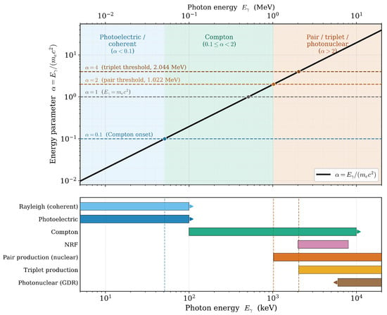
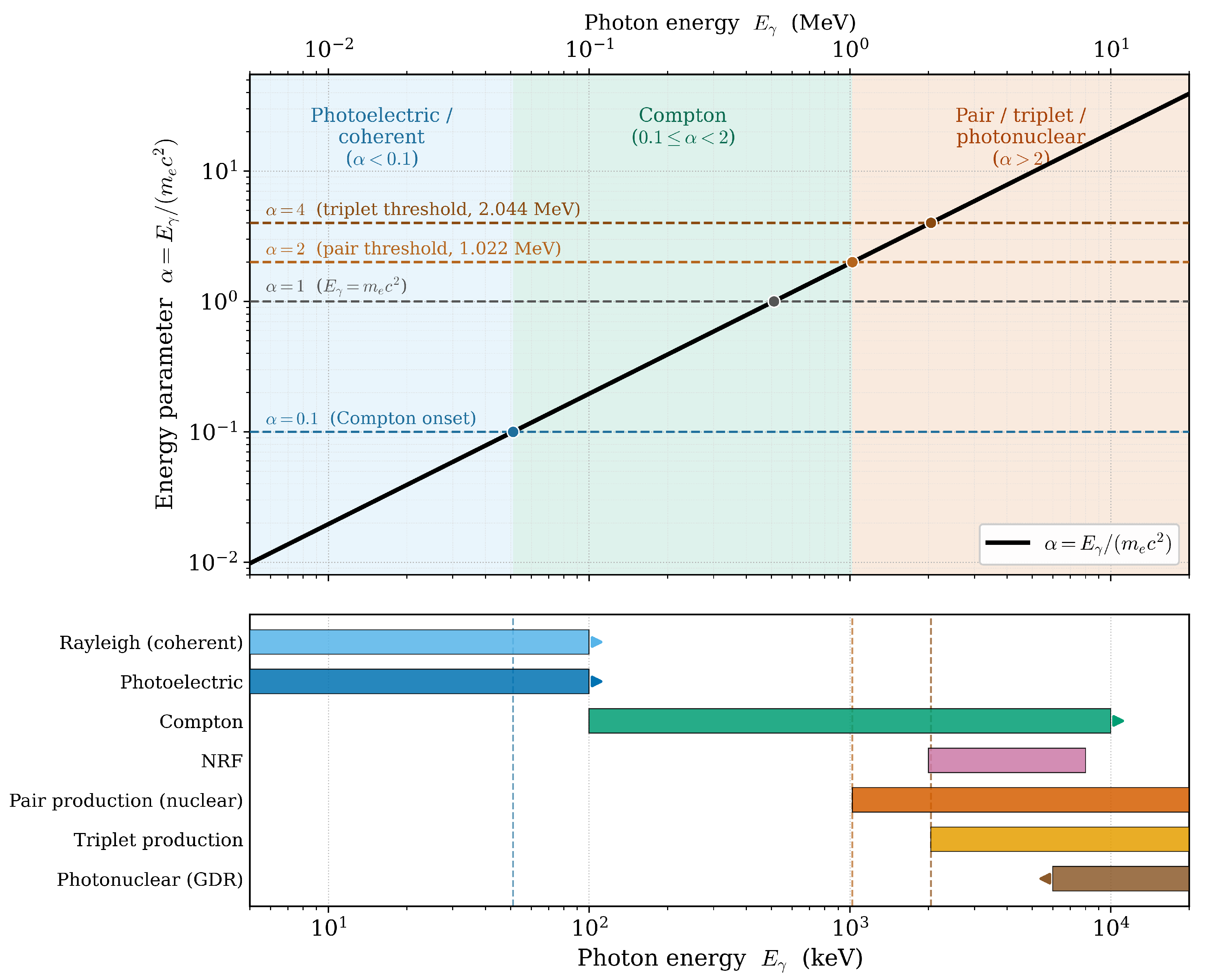
where is the photon energy and is the electron rest-mass energy. Three regimes emerge naturally, as illustrated in Figure 8.
Figure 8.
Dimensionless energy parameter versus photon energy on logarithmic axes. (Top) Because keV, the principal interaction thresholds map onto integer values of : where the photon energy equals the electron rest energy (), at the pair-production threshold ( MeV), and at the triplet-production threshold ( MeV). Dashed lines mark these crossings; the upper axis gives in MeV. Shaded bands delineate the photoelectric/coherent (), Compton (), and pair-production-and-above () regimes for photon–matter interactions. (Bottom) Photon energy ranges over which each process of Table 3 is significant or dominant; arrows denote ranges extending beyond the plotted window. The bands extended to ∼20 MeV span the full set of processes accessible with e-beams up to that energy.
3.2.1. Low Energy: Photoelectric Effect
This regime applies when , i.e., . The photon is completely absorbed by an inner-shell electron, which is then ejected from the atom. The cross-section scales approximately as [57]
so the process is the strongest for heavy materials (high Z) and drops sharply with photon energy. This strong Z-dependence makes the photoelectric effect the basis for several applications: in medical radiography and mammography (20–50 keV), the high contrast between bone (high-Z calcium) and soft tissue exploits this regime directly; in X-ray photoelectron spectroscopy (XPS), the ejected photoelectrons carry element-specific binding-energy information for surface chemical analysis. Compact accelerators at low beam energies, such as pyroelectric crystal accelerators and low-voltage electrostatic machines, naturally access this regime.
3.2.2. Intermediate Energy: Compton Scattering
This regime applies when , i.e., . Here photons scatter off outer electrons and lose only part of their energy, continuing in a new direction. This takes over once photon energies exceed the inner-shell binding energies of the target. For common structural metals, these K-edge energies are small, i.e., for iron, for chromium, and for nickel, so Compton scattering already dominates above roughly . Unlike the photoelectric effect, the Compton cross-section depends on electron density rather than atomic number, so heavy and light materials behave more similarly.
The total Compton cross-section is given by the Klein–Nishina formula [58]:
where is the classical electron radius and . The formalism provides two cross-sections: the total (cm2 or barns), used for attenuation, dose, and shielding calculations, and the differential (cm2 sr−1), used for scattered-photon spectra, angular distributions, and detector response. The differential form is [59,60]
where E and are the incident and scattered photon energies (the formula is also written in terms of wavelength ratios, since ). The scattered energy follows the Compton formula:
where is the scattering angle. For ,
Thomson scattering [61] is the classical low-energy limit, valid when . There the Klein–Nishina formula reduces to the Thomson cross-section [62]
with differential form
Because the Thomson cross-section scales as , the proton cross-section is suppressed by relative to the electron value and is negligible [62].
The near material independence and the well-defined angular and energy distributions of scattered photons make Compton scattering the basis for several applications: in radiation therapy, MV-range clinical linacs (4–25 MeV) operate squarely in this regime, where the near-material-independent cross-section gives relatively uniform dose in soft tissue regardless of bone or soft-tissue interfaces; in industrial non-destructive testing (NDT), Compton backscatter imaging with betatrons or C-band linacs at 1–10 MeV reveals internal voids, corrosion, and density variations in pipelines, aircraft panels, and thick-walled structures from single-sided access; in cargo and baggage screening, dual-energy Compton imaging at 3–9 MeV distinguishes organic materials (low electron density) from metals (high electron density) without opening containers; and in inverse-Compton X-ray sources, a laser photon backscattered off a relativistic electron beam gains energy by ∼, producing tunable, quasi-monochromatic X-ray or gamma-ray beams for nuclear resonance fluorescence (NRF) and medical imaging research. Compact accelerators (particularly RF linacs, betatrons, and Rhodotrons) are the primary photon sources in all of these applications.
3.2.3. High Energy: Pair Production
This regime applies when , i.e., . Above the threshold , a photon passing close to an atomic nucleus can convert into an electron–positron pair. The probability grows with energy and scales as , so it matters more for heavier materials, and at sufficiently high energies, pair production overtakes Compton scattering. The positron quickly annihilates with a nearby electron, releasing two back-to-back 511 keV gamma rays, a distinctive signature exploited in several applications. In positron emission tomography (PET), these coincident gamma rays are detected to produce three-dimensional images of metabolic activity. In high-energy physics experiments such as CMS [63] and ATLAS [64], pair production initiates electromagnetic showers used to measure gamma-ray and electron energies. In gamma-ray astronomy, satellite instruments such as Fermi-LAT convert incoming gamma rays into electron–positron pairs to determine their direction and energy. In nuclear security, compact linacs and betatrons above ∼6 MeV produce bremsstrahlung photons energetic enough to induce photofission in fissile materials such as uranium-235 and plutonium-239, identifying them inside cargo containers. All three interactions can also be exploited within a single application. A compelling example is cargo security screening, where a single compact linac at 3–15 MeV sequentially accesses all three regimes by tuning the beam energy: the photoelectric effect at low energies provides high-Z contrast for detecting lead shielding; Compton scattering at intermediate energies reveals density variations and organic versus metallic content; and pair production at higher energies induces photofission signatures that identify fissile nuclear materials (as noted above). Similarly, in radiation therapy all three processes contribute to dose deposition depending on tissue depth and beam energy, and the treatment planner must account for each regime to achieve the desired dose distribution. A recent proposal [65] suggests exploiting all three processes together to identify materials accurately and reduce false alarms, with application to airport baggage inspection. Table 3 summarizes applications of the three processes and beyond.
Table 3.
Photon–matter interaction processes accessible with electron beams up to ∼20 MeV and their applications.
A 5–20 MeV electron accelerator can produce X-rays and gamma rays from a high-Z converter (such as tungsten) and neutrons from a photoneutron converter (such as beryllium or heavy water). This enables several complementary interrogation techniques in one system. At 3–6 MeV it produces penetrating X-rays that image cargo contents, revealing dense materials and any concealing lead shielding; X-rays alone, however, cannot identify the specific material. At 6–10 MeV the X-rays can induce photofission in uranium-235 or plutonium-239, releasing distinctive neutron and gamma-ray signatures that distinguish nuclear materials from benign heavy metals such as steel or lead. At 10–15 MeV or more, X-rays on a converter (beryllium or heavy water) release neutrons that penetrate cargo and interact with nuclear materials in two ways: triggering fission in uranium or plutonium, and, when absorbed by other elements, prompting characteristic gamma-ray patterns that serve as elemental fingerprints. Combining X-ray and neutron scanning from one machine reduces false alarms and improves detection reliability. Operators adjust the beam energy to the task: lower for primary screening, higher for dense materials or suspected nuclear items. Rapid pulsing lets detectors separate prompt from delayed signals, aiding identification of specific nuclear materials.
Table 3 shows interaction processes and their applications. A single compact accelerator can sequentially access all three regimes by tuning beam energy, and this energy-tuning capability is the defining practical advantage of compact accelerators over fixed-energy radioisotope sources.
4. Conclusions
Particle accelerators have become indispensable tools across fundamental research, medical diagnostics, security screening, and many other applications. Large-scale accelerators, though few in number and often referred to as “Big Science,” remain central to scientific discovery and the development of advanced instrumentation. In contrast, thousands of small-scale accelerators serve as essential tools in daily applications, yet many of their capabilities remain underutilized.
This review has presented the operating principles of a broad range of compact accelerators—from betatrons, Rhodotrons, and RF linacs to permanent-magnet systems, dielectric-wall accelerators, pyroelectric crystals, electrostatic machines, and conduction-cooled SRF modules—and discussed how each can be tailored to many physics parameters and meet specific application requirements. When a beam in the keV–MeV energy range strikes a target, it produces bremsstrahlung photons whose interactions with matter are governed by three well-established mechanisms: the photoelectric effect, Compton scattering, and pair production, each dominant in a distinct energy regime accessible by tuning the beam energy. Compact accelerators are well suited to operate across all three regimes, and are utilized also for science discoveries. Beyond these principal processes, additional interactions including Rayleigh scattering and photonuclear reactions further extend their utility.
Taken together, the accelerator types reviewed here span a wide range of size, cost, and capability, offering practical solutions for applications in medicine, industry, security, environmental remediation, and space science. As technology continues to mature, particularly in superconducting RF, permanent-magnet focusing, and high-gradient structures, pyroelectric crystal accelerators are poised to play an increasingly central role in contemporary science and technology.
Funding
This research received no external funding. This work was prepared as part of official LLNL activities. This work was performed under the auspices of the U.S. Department of Energy by Lawrence Livermore National Laboratory under Contract DE-AC52-07NA27344. Release Number of this document: LLNL-JRNL-2020953.
Data Availability Statement
The information presented in this manuscript is primarily derived from the published literature, textbooks, and the author’s expertise and experience.
Acknowledgments
The author would like to thank B.E. Yoxall for supporting a portion of the time dedicated to concept development. The author is grateful to D.P. Grote for carefully reading the manuscript and providing helpful feedback.
Conflicts of Interest
The author declares no conflicts of interest.
References
- Roy, P.K.; Horsley, M.A.; Heppermann, S.G.; Harvey, Z.R.; Upadhyayula, S. Review of MeV Energy Scale Accelerators, Their Capabilities, and Common Applications. In Proceedings of the 15th International Particle Accelerator Conference (IPAC’24), Nashville, TN, USA, 19–24 May 2024; pp. 2002–2005. [Google Scholar]
- Agostinelli, S.; Allison, J.; Amako, K.A.; Apostolakis, J.; Araujo, H.; Arce, P.; Asai, M.; Axen, D.; Banerjee, S.; Barr, G.J.; et al. GEANT4—A Simulation Toolkit. Nucl. Instrum. Methods Phys. Res. Sect. A 2003, 506, 250–303. [Google Scholar] [CrossRef] [Scilit]
- Krane, K.S. Introductory Nuclear Physics; John Wiley & Sons: New York, NY, USA, 1987. [Google Scholar]
- National Institute of Standards and Technology (NIST). ESTAR: Stopping Power and Range Tables for Electrons. Available online: https://physics.nist.gov/PhysRefData/Star/Text/ESTAR.html (accessed on 25 May 2024).
- U.S. Department of Energy (DOE). Accelerators for America’s Future; Office of Science, U.S. Department of Energy: Washington, DC, USA, 2010.
- Hamm, R.W.; Hamm, M.E. (Eds.) Industrial Accelerators and Their Applications; World Scientific: Singapore, 2012. [Google Scholar]
- Lewellen, J.W.; Buechler, C.E.; Carlsten, B.E.; Dale, G.E.; Holloway, M.A.; Patrick, D.E.; Storms, S.A.; Nguyen, D.C. Space-Borne Electron Accelerator Design. Front. Astron. Space Sci. 2019, 6, 78. [Google Scholar] [CrossRef] [Scilit]
- International Atomic Energy Agency (IAEA). Compact Accelerators for Industrial and Societal Applications; Radiation Technology Series No. 4; IAEA: Vienna, Austria, 2017. [Google Scholar]
- Esarey, E.; Schroeder, C.B.; Leemans, W.P. Physics of Laser-Driven Plasma-Based Electron Accelerators. Rev. Mod. Phys. 2009, 81, 1229–1285. [Google Scholar] [CrossRef] [Scilit]
- Geddes, C.G.R.; Toth, C.; van Tilborg, J.; Esarey, E.; Schroeder, C.B.; Bruhwiler, D.; Nieter, C.; Cary, J.; Leemans, W.P. High-Quality Electron Beams from a Laser Wakefield Accelerator Using Plasma-Channel Guiding. Nature 2004, 431, 538–541. [Google Scholar] [CrossRef] [Scilit]
- Leemans, W.P.; Nagler, B.; Gonsalves, A.J.; Tóth, C.; Nakamura, K.; Geddes, C.G.R.; Esarey, E.; Schroeder, C.B.; Hooker, S.M. GeV Electron Beams from a Centimetre-Scale Accelerator. Nat. Phys. 2006, 2, 696–699. [Google Scholar] [CrossRef] [Scilit]
- Morel, E.; Kononenko, O.; Wheeler, J.; Ayeb, A.; Rousseau, P.; Lozano, M.; Tafzi, A.; Martelli, L.; André, Y.B.; Palacios, S.R.; et al. A transportable laser-plasma accelerator in the MeV range. Sci. Rep. 2025, 15, 29008. [Google Scholar] [CrossRef] [Scilit]
- Kilpatrick, W.D. Criterion for Vacuum Sparking Designed to Include Both RF and DC. Rev. Sci. Instrum. 1957, 28, 824–826. [Google Scholar] [CrossRef] [Scilit]
- Boyd, T.J. Kilpatrick’s Criterion; Report AT-1:82-28; Los Alamos National Laboratory, Group AT-1: Los Alamos, NM, USA, 1982.
- Wangler, T.P. RF Linear Accelerators, 2nd ed.; Wiley-VCH: Weinheim, Germany, 2008; p. 160. [Google Scholar]
- Jameson, R.A. RF Breakdown Limits. In High-Brightness Accelerators; Schempp, A., Shepard, K., Eds.; NATO ASI Series B, Vol. 137; Plenum Press: New York, NY, USA, 1988; p. 497. [Google Scholar]
- Loew, G.A.; Wang, J.W. Some Problems on RF Breakdown in Room Temperature Electron Linear Accelerators; Tech. Rep. SLAC/AP-051; Stanford Linear Accelerator Center: Stanford, CA, USA, 1986. [Google Scholar]
- Weiss, M. Introduction to RF Linear Accelerators; CERN: Geneva, Switzerland, 1994; Available online: https://cds.cern.ch/record/261732/files/p913.pdf (accessed on 25 June 2026).
- Takeda, H.; Billen, J. PARMILA; Internal Report LA-UR-98-4478; Los Alamos National Laboratory: Los Alamos, NM, USA, 2005.
- Batygin, Y.; Kurennoy, S.; Gorelov, D.; Yakovlev, V.; Fronk, T. Proton and Ion Linear Accelerators. In Proceedings of the U.S. Particle Accelerator School (USPAS), Stony Brook, NY, USA, 7 June 2021; Available online: https://uspas.fnal.gov/materials/21onlineSBU/onlineSBU-PILA.shtml (accessed on 25 June 2026).
- Simakov, E.I.; Dolgashev, V.A.; Tantawi, S.G. Advances in High Gradient Normal Conducting Accelerator Structures. Nucl. Instrum. Methods Phys. Res. Sect. A 2018, 907, 221–230. [Google Scholar] [CrossRef] [Scilit]
- Nanni, E.A.; Dolgashev, V.A.; Haase, A.; Neilson, J.; Tantawi, S.; Schaub, S.C.; Temkin, R.J.; Spataro, B. Prototyping High-Gradient mm-Wave Accelerating Structures. In Proceedings of the 8th International Particle Accelerator Conference (IPAC’17), Copenhagen, Denmark, 14–19 May 2017; pp. 2902–2904. [Google Scholar]
- Kutsaev, S.V.; Agustsson, R.; Arodzero, A.; Berry, R.; Bezhanov, A.; Boucher, S.; Chimalpopoca, O.; Diego, A.; Faillace, L.; Gavryushkin, D.; et al. Compact X-Band Electron Linac for Radiotherapy and Security Applications. Radiat. Phys. Chem. 2021, 185, 109494. [Google Scholar] [CrossRef] [Scilit]
- Dolgashev, V.; Romero, A.; Krasnykh, A.; Kuzikov, S.; Kostin, R.; Borchard, P. High Efficiency Traveling Wave Linac with Tunable Energy. In Proceedings of the 31st International Linear Accelerator Conference (LINAC’22), Liverpool, UK, 28 August–2 September 2022; pp. 727–730. [Google Scholar]
- Roy, P.K.; Yu, S.S.; Henestroza, E.; Eylon, S.; Shuman, D.B.; Ludvig, J.; Bieniosek, F.M.; Waldron, W.L.; Greenway, W.G.; Vanecek, D.L.; et al. Electron-Beam Diagnostic for Space-Charge Measurement of an Ion Beam. Rev. Sci. Instrum. 2005, 76, 023301. [Google Scholar] [CrossRef] [Scilit]
- Van Allen, J.A.; Ludwig, G.H.; Ray, E.C.; McIlwain, C.E. Observation of High Intensity Radiation by Satellites 1958 Alpha and Gamma. J. Jet Propuls. 1958, 28, 588–592. [Google Scholar] [CrossRef] [Scilit]
- Kerst, D.W. The Acceleration of Electrons by Magnetic Induction. Phys. Rev. 1941, 60, 47–53. [Google Scholar] [CrossRef] [Scilit]
- Kerst, D.W. Historical Development of the Betatron. Nature 1946, 157, 90–95. [Google Scholar] [CrossRef] [Scilit]
- Encyclopædia Britannica, Inc. betatron. In Encyclopædia Britannica; Encyclopædia Britannica, Inc.: Chicago, IL, USA; Available online: https://www.britannica.com/technology/betatron (accessed on 25 June 2026).
- Humphries, S., Jr. Principles of Charged Particle Acceleration; John Wiley & Sons: New York, NY, USA, 1986. [Google Scholar]
- Wiedemann, H. Particle Accelerator Physics, 4th ed.; Springer: Cham, Switzerland, 2015; pp. 60–63. [Google Scholar]
- Conte, M.; Mackay, W.W. An Introduction to the Physics of Particle Accelerators, 2nd ed.; World Scientific: Hackensack, NJ, USA, 2008; pp. 13–14. [Google Scholar]
- Pottier, J. A New Type of RF Electron Accelerator: The Rhodotron. Nucl. Instrum. Methods Phys. Res. Sect. B 1989, 40–41, 943–945. [Google Scholar] [CrossRef] [Scilit]
- Rhodotron. In Wikipedia. Available online: https://de.wikipedia.org/wiki/Rhodotron (accessed on 25 June 2026).
- Lancker, M.V.; Herer, A.; Clel, M.R.; Jongen, Y.; Abs, M. The IBA Rhodotron: An industrial high-voltage high-powered electron beam accelerator for polymers radiation processing. Nucl. Instrum. Methods Phys. Res. Sect. B 1999, 151, 242–246. [Google Scholar] [CrossRef] [Scilit]
- Halbach, K. Design of Permanent Multipole Magnets with Oriented Rare Earth Cobalt Material. Nucl. Instrum. Methods 1980, 169, 1–10. [Google Scholar] [CrossRef] [Scilit]
- Benedetti, S.; Grudiev, A.; Latina, A. High Gradient Linac for Proton Therapy. Phys. Rev. Accel. Beams 2017, 20, 040101. [Google Scholar] [CrossRef] [Scilit]
- Couprie, M.E.; Loulergue, A.; Labat, M.; Lehe, R.; Malka, V. Towards a Free Electron Laser Based on Laser Plasma Accelerators. J. Phys. B At. Mol. Opt. Phys. 2014, 47, 234001. [Google Scholar] [CrossRef] [Scilit]
- Caporaso, G.J.; Sampayan, S.; Chen, Y.-J.; Harris, J.; Hawkins, S.; Holmes, C.; Krogh, M.; Nelson, S.; Nunnally, W.; Paul, A.; et al. Compact Accelerator Concept for Proton Therapy. Nucl. Instrum. Methods Phys. Res. Sect. B 2007, 261, 777–781. [Google Scholar] [CrossRef] [Scilit]
- Batra, A.K.; Aggarwal, M.D. Pyroelectric Materials: Infrared Detectors, Particle Accelerators, and Energy Harvesters; SPIE Press: Bellingham, WA, USA, 2013. [Google Scholar]
- Brownridge, J.D. Pyroelectric X-ray Generator. Nature 1992, 358, 287–288. [Google Scholar] [CrossRef] [Scilit]
- Brownridge, J.D.; Shafroth, S.M. Self-Focused Electron Beams Produced by Pyroelectric Crystals on Heating or Cooling in Dilute Gases. Appl. Phys. Lett. 2001, 78, 1158–1160. [Google Scholar] [CrossRef] [Scilit]
- Geuther, J.; Danon, Y.; Saglime, F. Nuclear Reactions Induced by a Pyroelectric Accelerator. Phys. Rev. Lett. 2006, 96, 054803. [Google Scholar] [CrossRef] [Scilit]
- Kusano, H.; Oyama, Y.; Naito, M.; Nagaoka, H.; Kuno, H.; Shibamura, E.; Hasebe, N.; Amano, Y.; Kim, K.J.; Matias Lopes, J.A. Development of an X-ray Generator Using a Pyroelectric Crystal for X-ray Fluorescence Analysis on Planetary Landing Missions. Proc. SPIE 2014, 9213, 921316. [Google Scholar] [CrossRef] [Scilit]
- Cockcroft, J.D.; Walton, E.T.S. Experiments with High Velocity Positive Ions. (I) Further Developments in the Method of Obtaining High Velocity Positive Ions. Proc. R. Soc. Lond. A 1932, 136, 619–630. [Google Scholar] [CrossRef] [Scilit]
- Bromley, D.A. The Development of Electrostatic Accelerators. Nucl. Instrum. Methods 1974, 122, 1–34. [Google Scholar] [CrossRef] [Scilit]
- Kuffel, E.; Zaengl, W.S.; Kuffel, J. High Voltage Engineering: Fundamentals, 2nd ed.; Butterworth-Heinemann: Oxford, UK, 2000; Chapter 2. [Google Scholar]
- Kutschera, W. Progress in Isotope Analysis at Ultra-Trace Level by AMS. Int. J. Mass Spectrom. 2005, 242, 145–160. [Google Scholar] [CrossRef] [Scilit]
- Christophorou, L.G.; Olthoff, J.K.; Van Brunt, R.J. Sulfur Hexafluoride and the Electric Power Industry. IEEE Electr. Insul. Mag. 1997, 13, 20–24. [Google Scholar] [CrossRef] [Scilit]
- Posen, S.; Lee, J.; Seidman, D.N.; Romanenko, A.; Tennis, B.; Melnychuk, O.S.; Sergatskov, D.A. Advances in Nb3Sn Superconducting Radiofrequency Cavities Towards First Practical Accelerator Applications. Supercond. Sci. Technol. 2021, 34, 025007. [Google Scholar] [CrossRef] [Scilit]
- Dhuley, R.C.; Posen, S.; Geelhoed, M.I.; Prokofiev, O.; Thangaraj, J.C.T. First Demonstration of a Cryocooler Conduction Cooled Superconducting Radiofrequency Cavity Operating at Practical CW Accelerating Gradients. Supercond. Sci. Technol. 2020, 33, 06LT01. [Google Scholar] [CrossRef] [Scilit]
- Dhuley, R.C.; Gonin, I.; Kazakov, S.; Khabiboulline, T.; Sukhanov, A.; Yakovlev, V.; Saini, A.; Solyak, N.; Sauers, A.; Thangaraj, J.C.T.; et al. Design of a 10 MeV, 1000 kW Average Power Electron-Beam Accelerator for Wastewater Treatment Applications. Phys. Rev. Accel. Beams 2022, 25, 041601. [Google Scholar] [CrossRef] [Scilit]
- Kapchinskij, I.M.; Teplyakov, V.A. Linear Ion Accelerator with Spatially Homogeneous Strong Focusing. Prib. Tekh. Eksp. 1970, 2, 19–22. (In Russian) [Google Scholar]
- Stokes, R.H.; Wangler, T.P.; Crandall, K.R. The Radio-Frequency Quadrupole—A New Linear Accelerator. IEEE Trans. Nucl. Sci. 1981, 28, 1999–2005. [Google Scholar] [CrossRef] [Scilit]
- O’Shea, P.G.; Butler, T.A.; Lynch, M.T.; McKenna, K.F.; Pongratz, M.B.; Zaugg, T.J. A linear accelerator in space: The Beam Experiment Aboard a Rocket. In Proceedings of the 1990 Linear Accelerator Conference, Albuquerque, NM, USA, 10–14 September 1990. [Google Scholar]
- Thomas, L.H. The Paths of Ions in the Cyclotron I. Orbits in the Magnetic Field. Phys. Rev. 1938, 54, 580–588. [Google Scholar] [CrossRef] [Scilit]
- Pratt, R.H.; Ron, A.; Tseng, H.K. Atomic Photoelectric Effect Above 10 keV. Rev. Mod. Phys. 1973, 45, 273–325. [Google Scholar] [CrossRef] [Scilit]
- Nelms, A.T. Graphs of the Compton Energy-Angle Relationship and the Klein-Nishina Formula from 10 keV to 500 MeV; NBS Circular 542; National Bureau of Standards, U.S. Department of Commerce: Washington, DC, USA, 1953.
- Klein, O.; Nishina, Y. Über die Streuung von Strahlung durch freie Elektronen nach der neuen relativistischen Quantendynamik von Dirac. Z. Phys. 1929, 52, 853–868. [Google Scholar] [CrossRef] [Scilit]
- Evans, R.D. The Atomic Nucleus; McGraw-Hill: New York, NY, USA, 1955; pp. 674–676. [Google Scholar]
- Thomson Scattering. In Wikipedia. Available online: https://en.wikipedia.org/wiki/Thomson_scattering (accessed on 25 June 2026).
- Jackson, J.D. Classical Electrodynamics, 3rd ed.; John Wiley & Sons: New York, NY, USA, 1998; Chapter 14; p. 695. [Google Scholar]
- CMS Collaboration. The CMS Experiment at the CERN LHC. J. Instrum. 2008, 3, S08004. [Google Scholar] [CrossRef] [Scilit]
- ATLAS Collaboration. The ATLAS Experiment at the CERN Large Hadron Collider. J. Instrum. 2008, 3, S08003. [Google Scholar] [CrossRef] [Scilit]
- Roy, P.K. X-Ray Image-Based Non-Invasive Detection of Concealed Objects; Unpublished LDRD Proposal No. LLNL-PROP-2016458; Lawrence Livermore National Laboratory: Livermore, CA, USA, 2026. [Google Scholar]

Disclaimer/Publisher’s Note: The statements, opinions and data contained in all publications are solely those of the individual author(s) and contributor(s) and not of MDPI and/or the editor(s). MDPI and/or the editor(s) disclaim responsibility for any injury to people or property resulting from any ideas, methods, instructions or products referred to in the content. |
© 2026 by the author. Licensee MDPI, Basel, Switzerland. This article is an open access article distributed under the terms and conditions of the Creative Commons Attribution (CC BY) license.