


Abstract
Nonlinear kickers (NLKs) enable off-axis injection in ultralow-emittance storage rings by providing a strong kick to the injected beam while remaining nearly transparent to the stored beam. In hybrid schemes, a conventional four-kicker bump defines the injected trajectory, and the NLK reduces the first-turn action under constrained beam offset and optics conditions. Effective operation additionally requires stable and reproducible first-turn injection trajectories. We develop a compact action–angle framework that expresses NLK dynamics in terms of Courant–Snyder invariants and yields an analytical bound on achievable action reduction. This formulation provides direct design rules for NLK placement, phase advance, injected-beam offset, and kicker field profile. Within this framework, we identify the 8-wire NLK as a practical baseline and extend its design by relaxing the square-geometry constraint, enabling inward shifting of the off-axis field peak while preserving on-axis field and gradient cancellation. Application to the NSLS-II lattice shows how aperture, pulsed-power, and mechanical constraints combine to determine a coupled design solution. Multi-turn tracking confirms that candidate NLK locations maintain sufficient stay-clear (aperture-clearance) margin, while the optimized wire geometry reduces the required current and Lorentz force load. The results establish a unified approach for NLK-assisted injection design and provide a practical pathway for upgrades in diffraction-limited storage rings.
1. Introduction
Off-axis injection is a central challenge in ultralow-emittance storage rings, where the dynamic aperture is often comparable to or smaller than the injected-beam oscillation amplitude [1,2,3,4]. Conventional four-kicker bump schemes rely on sufficient acceptance to capture the injected beam, but in diffraction-limited lattices the reduced aperture makes residual oscillations a primary limitation.
On-axis swap-out injection has therefore emerged as the baseline solution for future facilities [5,6,7,8,9]. However, swap-out demands substantial supporting infrastructure, including a high-current full-energy injector, a high-power beam dump, and in some cases an accumulator ring. These systems significantly increase cost and operational complexity.
Nonlinear kickers (NLKs) provide an alternative by delivering a strong transverse kick to the injected beam while remaining nearly transparent to the stored beam. This property has motivated their adoption in several facilities and their consideration for next-generation light sources [10,11,12,13,14,15]. In an idealized implementation, NLKs could be used as a standalone injection system, with the injected trajectory, septum conditions, and kicker field optimized simultaneously. In practice, however, most applications correspond to retrofit scenarios in which NLKs are added to an existing four-bump injection system [16].
In this hybrid configuration, the injected trajectory is largely fixed by the upstream bump and septum geometry, while the NLK acts to reduce the injected-beam action on the first turn. Effective NLK operation additionally requires stable and reproducible injection trajectories, since the achievable action reduction depends sensitively on the injected-beam offset and phase-space coordinates at the NLK location. The resulting performance is therefore constrained by the available beam offset, lattice optics, kicker-field profile, and trajectory control, defining a coupled design problem that differs qualitatively from both conventional bump injection and fully NLK-based schemes.
While previous studies have demonstrated the feasibility of NLK-assisted injection and explored specific implementations, a compact framework that directly links beam dynamics, lattice design, and hardware constraints remains lacking. In particular, the interplay between phase advance, injected-beam offset, and nonlinear field profile has not been expressed in a form that yields simple and general design rules.
In this work, we develop an action–angle formulation that expresses NLK-induced dynamics in terms of Courant–Snyder invariants. The resulting framework yields an analytical bound on action reduction and provides quantitative design rules for NLK placement, optics selection, and field configuration within a hybrid injection scheme.
We apply the method to the NSLS-II lattice as a representative retrofit case. Candidate NLK locations, field configurations, and engineering constraints are evaluated within a unified beam-dynamics and hardware-design framework. Although the numerical optimization is specific to NSLS-II, the underlying methodology is applicable to both retrofit upgrades and future diffraction-limited storage rings.
MAX IV demonstrates that transparent off-axis injection can be achieved using a multipole injection kicker that replaces conventional bump-based injection [9]. In contrast, the present work focuses on a hybrid approach in which the existing four-kicker bump is retained and the NLK provides first-turn action reduction. This strategy preserves the established injection configuration while minimizing operational impact.
2. Injection Design Boundary
A useful starting point is to define the injection regime that an NLK is intended to improve. In a conventional four-bump scheme, the injected beam arrives at the septum with a finite offset chosen to clear the stored beam and downstream aperture. When dynamic aperture is sufficiently large, this approach provides acceptable capture. In ultralow-emittance rings, however, the reduced acceptance makes the residual first-turn oscillation a dominant limitation.
At the opposite extreme, a fully NLK-based injection scheme treats the injected trajectory, septum conditions, and kicker field as a single coupled optimization problem. In this limit, the injected offset at the NLK can be chosen to maximize action reduction and field efficiency. Most upgrade scenarios do not offer this flexibility. Instead, the injected beam reaching the NLK is already constrained by the existing four-bump optics, septum geometry, aperture limits, and operational requirements.
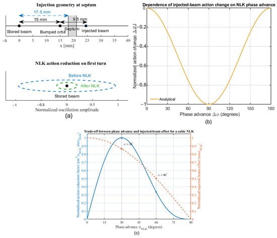
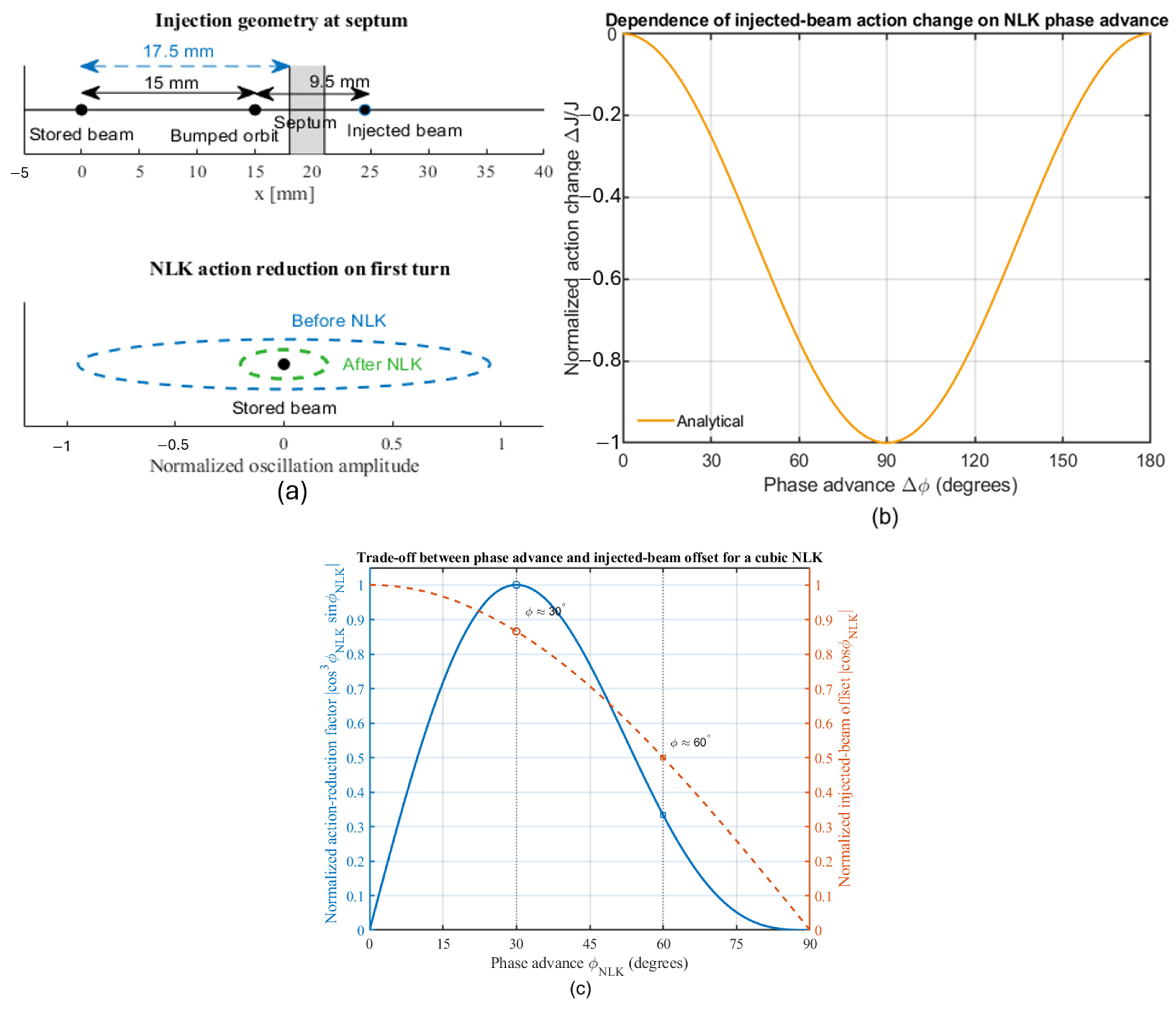
These considerations define three regimes: conventional four-bump injection, hybrid four-bump-plus-NLK injection, and fully NLK-based injection. The hybrid regime is the most relevant for NSLS-II (see Figure 1a) and similar facilities. In this case, the injected-beam offset at the NLK is intermediate—smaller than in an NLK-only design but larger than the final matched trajectory—and is bounded by septum clearance, dynamic aperture, physical aperture, and available orbit control.
Figure 1.
(a) Injection geometry and NLK action. Top: the four-kicker bump displaces the stored beam by ~15 mm, allowing the injected beam to clear the septum and resulting in an injected-beam offset of ~9.5 mm [17]. Bottom: the injected beam initially oscillates with large amplitude (blue, dashed ellipse) and is reduced by the NLK to a smaller amplitude (green, dashed ellipse), while the stored beam remains near the on-axis region. The oscillation amplitudes are normalized to the initial injected-beam oscillation amplitude immediately downstream of the septum. (b) Phase dependence of the ideal normalized action reduction. In the linear-response limit with freely adjustable kick amplitude, the minimum action change is , reaching at . Equivalently, the residual action satisfies . (c) Trade-off between phase advance and injected-beam offset for a cubic NLK. The blue curve shows the normalized action-reduction factor and the orange dashed curve shows the normalized injected-beam offset. Because the kick scales as with , the effective action-reduction term scales as , which peaks near . The ideal optimum is therefore not realizable for a pure cubic device.
In a hybrid injection system, the initial injected-beam action is largely set by the separation required at the pulsed septum. This separation is constrained by the septum knife thickness and by the minimum clearances between the knife edge, the bumped stored beam, and the injected beam. These hardware constraints determine the injected trajectory entering the storage ring and therefore set the action that must initially be accepted. The NLK then acts to reduce this septum-defined action as early as possible on the first turn, motivating placement close to the injection point.
Within this constrained regime, key design variables become inherently coupled. The preferred NLK location is determined not only by phase advance but also by whether a usable injected-beam offset can be realized within aperture limits. The optimal phase advance is therefore not a single value, as both the achievable offset and the kick efficiency depend on the NLK field profile. Similarly, the choice of hardware is governed not only by peak field strength, but by how effectively the available offset range is converted into action reduction while remaining technically feasible.
Formulating the problem in this way establishes a direct connection between lattice dynamics and device implementation and clarifies why the NSLS-II case is representative of a broader class of retrofit scenarios in diffraction-limited storage rings. However, a quantitative understanding of these trade-offs—and the limits they impose on achievable action reduction—requires a quantitative description that directly connects beam dynamics and hardware design variables.
The injected trajectory defined by the four-kicker bump (Figure 1a) therefore sets the initial condition for NLK action and establishes the practical design boundary for hybrid injection. Based on this boundary, the following section develops an action–angle framework that expresses the resulting dynamics in terms of Courant–Snyder invariants. This formulation leads to simple analytical bounds and provides the basis for the optics design rules derived in Section 3.
3. Action–Angle Framework and Optics Design Rules
3.1. Thin-Kick Action Reduction
A compact action–angle formulation provides a clear description of NLK-driven injection dynamics. In linear optics, the horizontal motion of the injected centroid can be written in Courant–Snyder normalized form
where and are the Twiss parameters, is the betatron phase, and the action measures the oscillation amplitude. The injected centroid executes betatron oscillations because it enters the storage ring with a finite phase-space mismatch relative to the stored-beam closed orbit. Equation (1) describes the centroid motion; finite-emittance effects are considered later in Section 3.4.
An NLK is modeled as a thin, position-dependent kick at
with action change
A positive kick K corresponds to a positive horizontal angular deflection. The injected-beam offset and angle are defined relative to the stored-beam reference orbit, and follows the Courant–Snyder phase convention of Equation (1).
Using the Courant–Snyder invariant, the resulting action change can be expressed as
where denotes the upstream action, and is the injected-beam offset at the NLK. In the moderate-kick limit, the leading-order behavior reduces to
Equation (5) provides the central design relation used throughout the remainder of this section. It shows that action reduction is governed by three coupled factors: (i) the lattice optics through β and phase advance, (ii) the injected-beam offset determined by the upstream injection system, and (iii) the NLK field profile through the sampled kick . The design rules developed in Section 3.2, Section 3.3, Section 3.4 and Section 3.5 follow directly from these three dependencies.
3.2. Maximum Achievable Reduction of Injected Action
Consider an injected particle with upstream Courant–Snyder action arriving at the NLK with phase advance . The injection reference point is taken to be the septum exit, which defines for the injection trajectory discussed in this work. The phase origin is chosen at the same location, where the injected centroid is approximated as a predominant position-offset state in normalized phase space, corresponding to 0. The phase at the NLK is therefore given by the horizontal betatron phase advance from the injection point, . The local injected-beam offset at the NLK is
where
At , the injected-beam offset becomes For m, this corresponds to
where denotes expressed in . Thus, for example, μm yields mm.
Using the thin-lens approximation and taking , the downstream action is with
where . The first term can reduce the action, while the second is a positive-definite contribution that limits the achievable reduction.
If were freely adjustable, minimizing gives
leading to
Substituting yields
This result assumes independent control of the kick amplitude and therefore represents an idealized upper bound. The reduction improves monotonically with and reaches at (Figure 1b). At , the bound gives , corresponding to a factor-of-four reduction in action.
In a cubic NLK, however, the kick depends on the following offset:
The beneficial term then scales as
which peaks at . Thus, maximizes the ideal bound, whereas maximizes the effectiveness of a fixed cubic device. For a physically realizable cubic NLK with finite strength , the formal 90° limit is not realizable in practice because implies .
A phase near 60° provides a practical compromise between achievable kick strength and effective action reduction (Figure 1c). The practical importance of the phase condition is illustrated by Table 1. A favorable phase advance is necessary but not sufficient: the injected offset must also be large enough for the cubic NLK to sample a meaningful field. The ID2 upstream point has , but mm is too small to generate an efficient kick, so the NLK operates in the weak-field tail, and the achievable action reduction is limited. By contrast, the downstream ID1 and ID2 candidates combine a usable offset with a more practical phase advance and therefore provide substantially better performance.
Table 1.
Candidate NLK locations in terms of injected-beam offset, horizontal beta function, optimal kick, phase advance, and action-reduction estimate. The injected-beam offsets are based on the measured and simulated first-turn injection trajectories discussed in Section 6. The phase advance denotes the horizontal betatron phase advance from the injection reference point (septum exit) to the candidate NLK location. Efficient reduction requires both a usable injected offset and favorable phase. The column gives the ideal kick-based action-reduction estimate; practical NLK efficiency also requires sufficient injected offset to sample the nonlinear field. The listed values of were obtained from single-particle (centroid) tracking by scanning the NLK kick amplitude and identifying the value that minimizes the downstream action. They therefore represent numerically optimized kicks for the local trajectory and optics, rather than direct evaluations of Equation (8). For ID2 downstream, the three values correspond to the following: (i) centroid action reduction obtained from single-particle tracking with an optimized kick, (ii) ideal dipole-kick tracking, in which all particles receive the same correction, and (iii) realistic 8-wire tracking using the position-dependent NLK field. The progression illustrates the effect of finite-beam-size dilution and nonlinear field sampling.
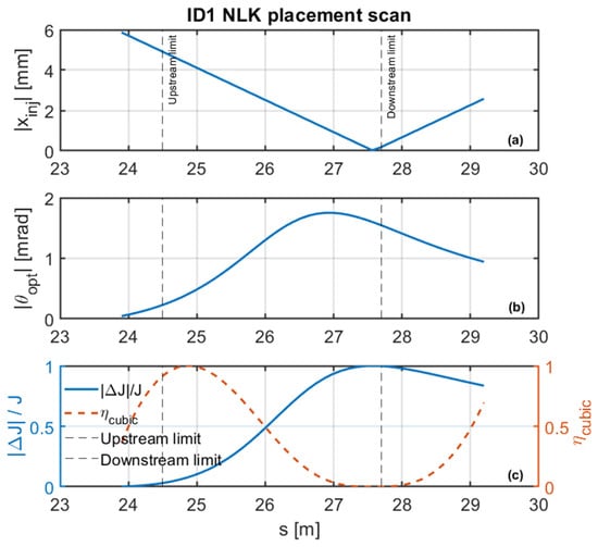
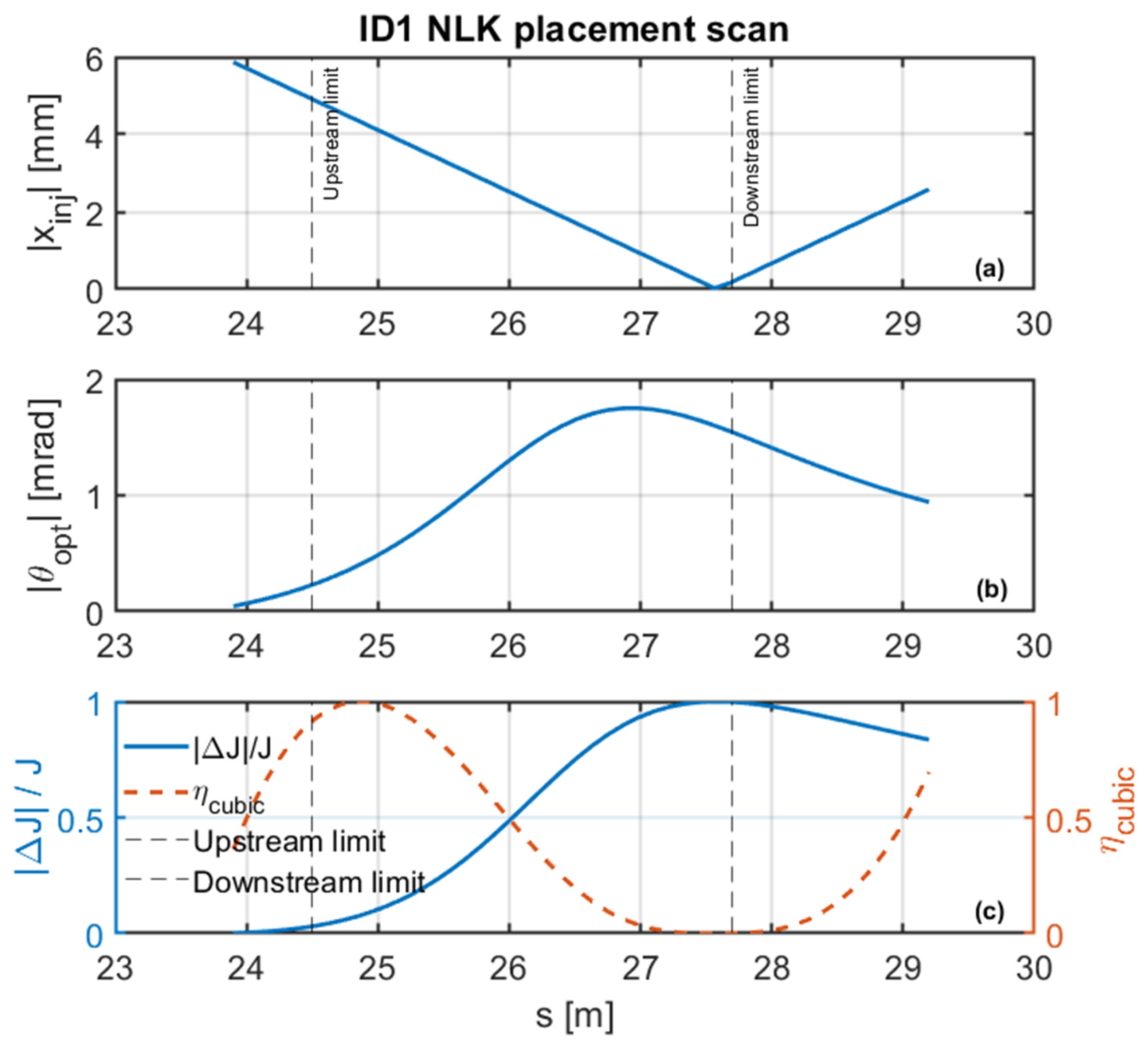
Figure 2 illustrates the continuous placement scan for candidate NLK locations within the available ID1 installation region. The upper panel shows the injected-beam offset, the middle panel shows the corresponding optimal kick angle, and the lower panel compares the ideal action-reduction bound of Equation (9) with the normalized practical cubic-NLK efficiency. As the NLK location approaches the formal phase-advance region, the ideal action reduction improves, and approaches unity. At the same time, however, the injected-beam offset collapses toward zero, causing the practical cubic-NLK efficiency to deteriorate rapidly because the device operates increasingly in the weak-field tail of the nonlinear profile. Conversely, locations with large injected-beam offsets provide stronger field sampling but suffer from weak phase leverage and therefore limited action reduction. The practical operating region therefore emerges from a coupled compromise between the phase advance and usable injected-beam offset rather than from optimization of either quantity independently.
Figure 2.
Continuous scan of candidate NLK placement within the available ID1 installation region. The dashed lines indicate the upstream and downstream boundaries of the available installation region in ID1. The injected-beam offset (a), optimal kick (b), and normalized action-reduction metrics (c) show that the formal 90° phase-advance optimum is not practical when the injected offset becomes too small. The usable operating region is therefore determined by the combined phase–offset condition.
In particular, the ID2 upstream location demonstrates that a phase advance close to does not guarantee efficiency if the injected offset is too small to sample the nonlinear field effectively. In practice, finite kick strength, limited field quality over offset, and lattice nonlinearities further reduce performance. For the configurations examined here, a single NLK typically achieves , depending on phase advance, injected-beam offset, and field profile.
3.3. Horizontal Beta Function: Leverage Versus Aperture
The horizontal beta function introduces a fundamental trade-off. The required kick strength scales approximately as
so larger reduces the required current. At the same time, the beam size scales as , reducing the available aperture margin.
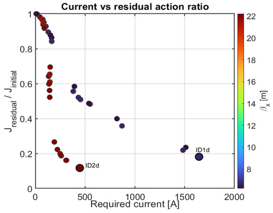
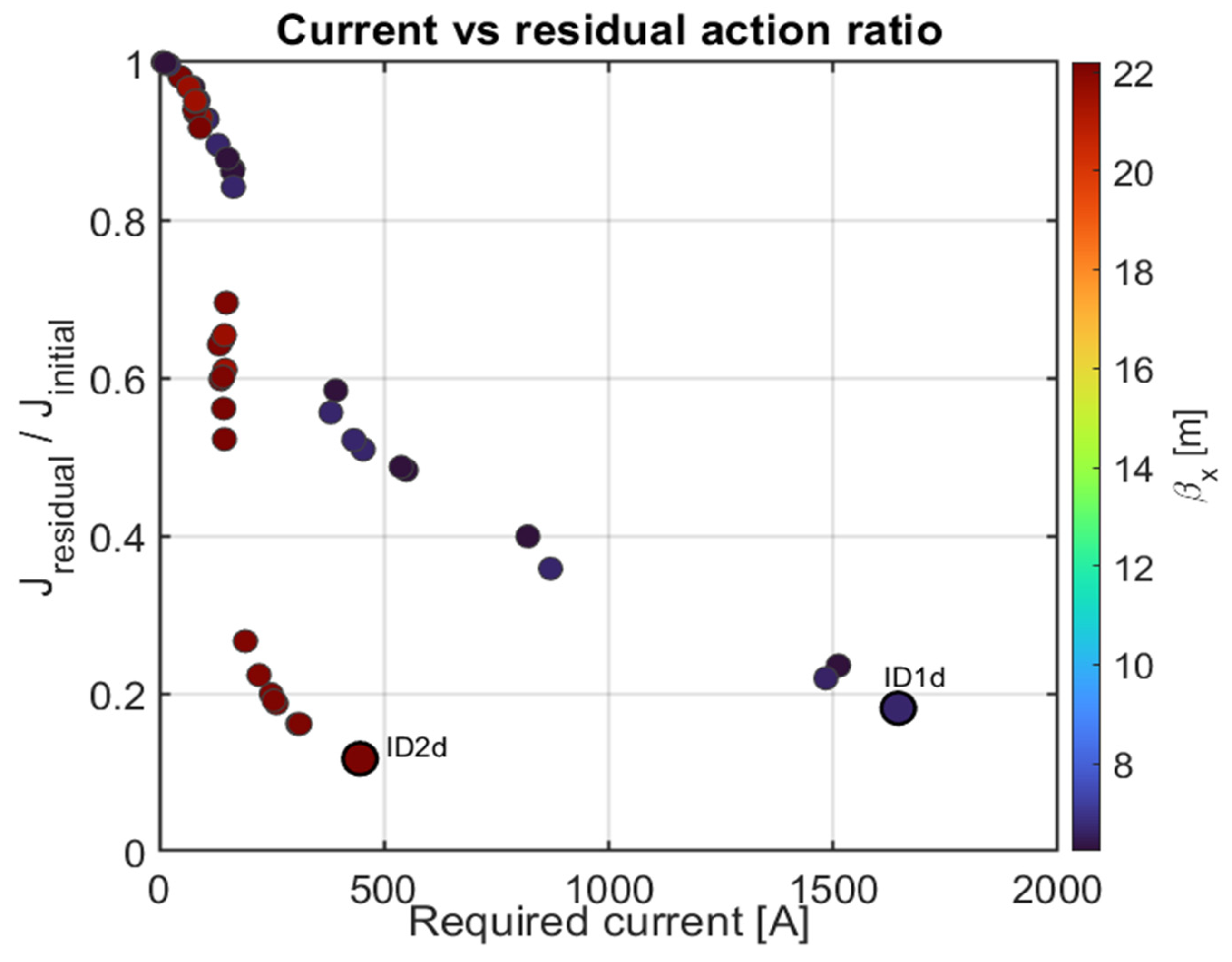
The optimal location therefore balances reduced kick strength and sufficient aperture, rather than maximizing alone. Figure 3 illustrates this trade-off using a Pareto comparison of required current and residual action. From the optics-and-current perspective, the ID2 downstream location provides the strongest compromise, achieving both low current and low residual action. As discussed in Section 7, the final prototype selection must also account for aperture, integration, and operational constraints.
Figure 3.
Pareto comparison of candidate NLK locations in terms of required current and residual action ratio . Lower values on both axes correspond to improved performance. Color indicates the local horizontal beta function at each candidate location. Only Pareto-front candidate locations are labelled for clarity. From the optics-and-current perspective, the ID2 downstream location provides the strongest performance compromise between reduced current and effective action reduction. Final prototype selection must also account for aperture, integration, and operational constraints. The color scale further shows that the lowest-current, lowest-residual-action region coincides with locations of larger horizontal . The calculation assumes a 0.5 m active magnetic length, used to convert the required kick into the corresponding current estimate.
This optics preference must still be filtered through the physical-aperture constraint. In particular, a high- location is not automatically usable if the local stay-clear aperture cannot accommodate the required NLK chamber gap. This aperture constraint is evaluated explicitly in the NSLS-II prototype selection discussed in Section 7.
3.4. Finite Injected-Beam Size and Nonlinear-Kick Dilution
The action–angle analysis above describes the centroid response and therefore represents the ideal limit in which the injected beam samples a single NLK kick. For a real injected bunch, the finite horizontal beam size causes particles at different transverse positions to sample different parts of the nonlinear field. Here, dilution refers to the reduction in correction efficiency caused by the finite transverse beam size sampling different kick amplitudes. Filamentation refers to the subsequent phase-space decoherence of the corrected distribution under nonlinear transport. If the centroid is located at and the NLK strength is chosen so that , an individual particle with receives a residual kick
Thus, even when the centroid kick is optimized, nonlinear field variation adds angular spread across the bunch and dilutes the action reduction relative to an ideal dipole kick, for which all particles receive the same correction.
Table 2 quantifies this finite-beam-size dilution at ID2 downstream. The ideal centroid-matched dipole kick reduces the mean horizontal action by 87%, consistent with the 88% analytical limit, whereas the realistic 8-wire field gives a 74% reduction because the finite injected distribution samples different kick strengths.
Table 2.
Finite-beam-size dilution of NLK action reduction for the 4-bump scheme at ID2 downstream. The no-NLK injected-beam action is . Analytical modeling and ideal-dipole tracking give 88% and 87% reductions, respectively, whereas the realistic 8-wire x-dependent kick gives a 74% reduction because of nonlinear kick variation and filamentation.
The finite-beam-size response depends on the injected-beam phase-space distribution, injected-beam offset, and the local curvature of the NLK field, so the centroid-based action bound does not by itself determine the full distribution response.
3.5. First-Turn Placement and Aperture-Protection Strategy
Because the injected-beam action is largely set by the septum-limited injection geometry, the first NLK should be placed early on the first turn. Early correction minimizes nonlinear phase distortion and centroid decoherence before compensation and reduces the chance that the large injected excursion encounters downstream aperture restrictions.
The NLK chamber introduces a fixed vertical aperture, so an upstream scraper is used to bound the injected-beam phase space before it reaches the device. The required setting is determined by the optical transport from the scraper to the NLK and is summarized in Table 3.
Table 3.
Scraper half-gap settings required for NLK protection and corresponding equivalent IVU half-gaps based on normalized vertical acceptance. Equivalent IVU values are obtained by matching at the scraper and IVU locations. The calculations use = 26.2 m at the scraper, = 3.5 m and 7.1 m at the ID1 NLK and ID2 NLK, respectively, and = 6.9 m at the reference IVU location. Momentum-acceptance tracking with these scraper settings shows no reduction relative to the baseline over the scanned interval , indicating that the scraper does not define the limiting off-momentum aperture. The scraper settings include a 0.9 safety factor applied to the NLK aperture constraint.
For a 6.0 mm full NLK gap, the selected scraper half-gaps are 7.4 mm for ID1 and 5.2 mm for ID2. For the relaxed 7.0 mm ID2 gap, the required setting is 6.0 mm. These settings provide a practical protection boundary for commissioning and operation.
To screen stored-beam impact, the scraper settings were converted to equivalent IVU half-gaps using normalized vertical acceptance. The ID2 6 mm gap case is slightly tighter than a typical 3 mm IVU half-gap, whereas the ID2 7 mm gap case is comparable.
Momentum-acceptance tracking with the scraper apertures included gives the same accepted range as the baseline lattice over the scanned interval, and . Thus, within the evaluated aperture model, the scraper does not define the limiting off-momentum aperture and is not expected to introduce a dominant Touschek-lifetime limitation.
Low dispersion at the NLK location is also preferred. Because the injected beam arrives with finite offset, nonzero dispersion introduces momentum-dependent position shifts, leading to variation in the experienced kick and broadening of the downstream action distribution. While operation in flatter regions of the NLK field can partially mitigate this effect, minimizing dispersion provides the most robust solution.
4. Device Concepts and Practical Design Selection
The optics rules developed in Section 3 define the required beam conditions at the NLK. The remaining question is which magnet concept can realize these conditions while preserving stored-beam transparency and remaining technically feasible. This is not purely a field-shaping problem: a viable NLK must simultaneously satisfy beam-dynamics, pulsed-power, mechanical, and vacuum constraints.
Several candidate concepts were examined, including the 8-wire configuration, the double-dipole-kicker (DDK) concept [18], and multi-wire extensions. All are designed to produce negligible field and gradient near the stored-beam orbit while providing a strong off-axis kick at the injected-beam position. Their differences lie in how efficiently they generate usable field, how close the peak can be brought toward the axis, and how much implementation complexity is introduced.
The 8-wire concept is adopted as the reference family because it combines strong geometric symmetry with practical implementability. Its symmetry provides a broad near-axis region of low field and low gradient, improving stored-beam transparency and reducing sensitivity to small alignment or excitation errors. In the first stage of this study, a geometrically symmetric 8-wire configuration was used to establish the basic field scaling and design rules. In the later optimization, this constraint was relaxed by allowing the horizontal and vertical wire coordinates to vary independently. This expanded design space improves the ability to shift the off-axis field peak inward while retaining the on-axis cancellation conditions required for stored-beam transparency.
The goal of this section is therefore not only to compare field profiles, but to establish a practical design logic. The symmetric 8-wire configuration is first used as the reference model for understanding field scaling. The relaxed-symmetry 8-wire geometry is then introduced as the optimized implementation. Alternative geometries, including the DDK and 12-wire concepts, are briefly compared in terms of peak placement, efficiency, robustness, and implementation complexity.
4.1. Eight-Wire NLK Reference Scaling and Relaxed-Symmetry Optimization
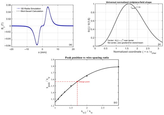
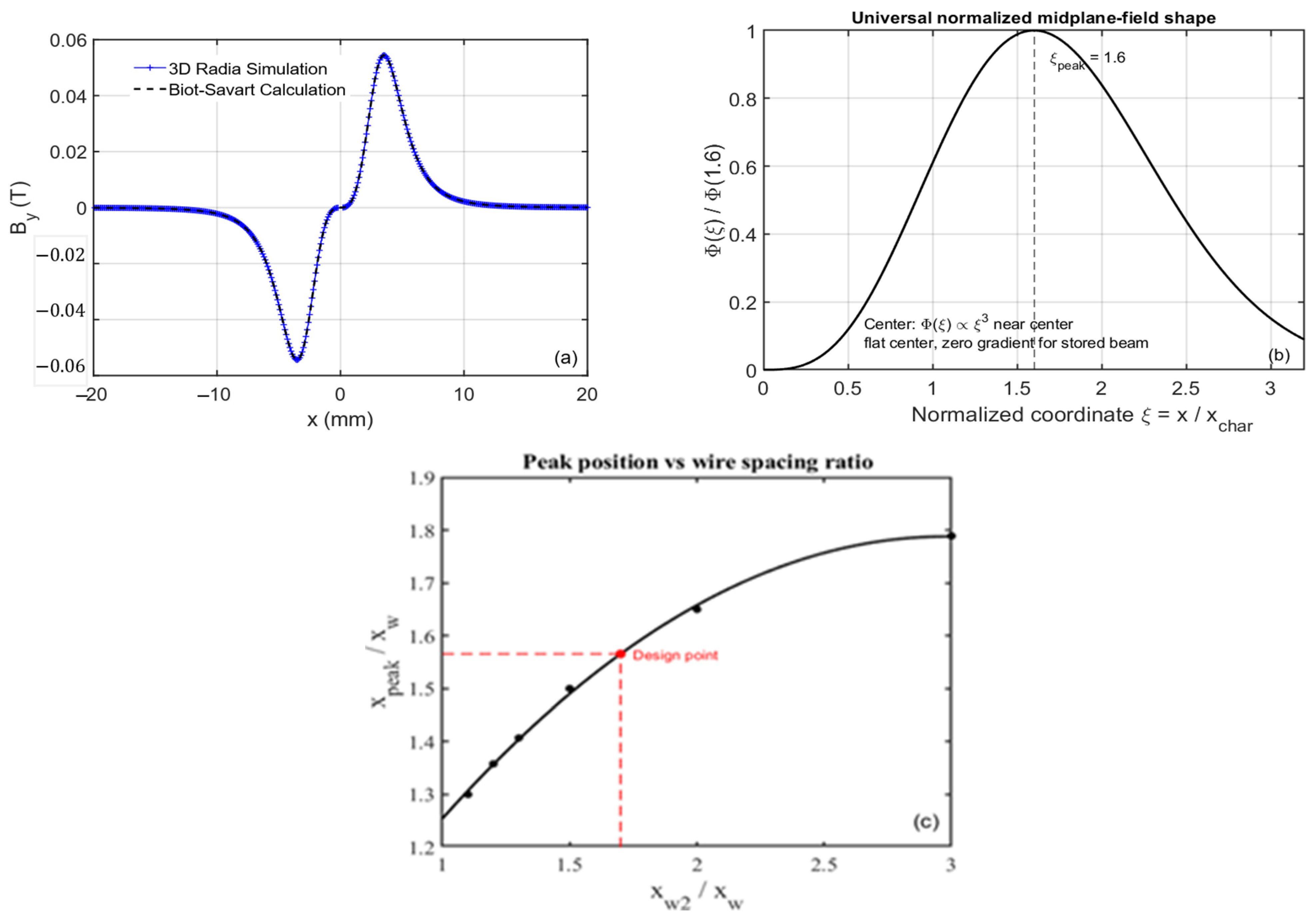
The 8-wire NLK is modeled using the line-current approximation [19,20], with validation against a full 3D Radia model [21]. The analytical field model is based on superposition of two four-wire quartets. The underlying four-wire building block and its closed-form midplane field expression are summarized in Appendix A and form the basis of the normalized eight-wire scaling relations developed below. As shown in Figure 4a, the simplified Biot–Savart description captures the midplane magnetic-field behavior of the physical NLK structure with good accuracy. This agreement justifies using the analytical model for rapid geometry scans and field optimization.
Figure 4.
Eight-wire NLK field scaling and geometry optimization. (a) Mid-plane magnetic field generated by a reference eight-wire NLK geometry, comparing the Biot–Savart model (black dashed) with a full 3D Radia simulation (blue) [21]. The agreement validates the analytical description for field analysis and optimization. (b) Universal scaling of the symmetric 8-wire reference geometry. The normalized midplane field , with , shows a peak near ≈ 1.6 and cubic near-axis behavior, , which ensures a flat center and zero gradient for the stored beam. The same shape function defines the normalized kicker efficiency through Equation (18), with maximum efficiency obtained when the injected beam samples the off-axis peak region. (c) Dependence of the normalized peak position on the outer-to-inner wire spacing ratio for the symmetric reference family. The peak shifts outward as the spacing ratio increases due to the growing contribution of the outer quartet. The black circles represent numerical field-calculation results for different wire-spacing ratios. The solid curve is a second-order polynomial fit to the scan data, , and the red point marks the selected reference geometry , for which .
To evaluate the sensitivity of the design to the available chamber aperture, the 8 mm, 7 mm, and 6 mm full-vertical-gap cases are treated as a parametric geometry scan. Unless otherwise noted, the selected baseline prototype configuration discussed in later sections corresponds to the 6 mm full-gap design. For the symmetric 8-wire reference geometry, the midplane field can be written in the universal normalized form
where is the characteristic transverse scale set by the wire geometry, and is a dimensionless shape function. For the strictly symmetric reference case, . The corresponding kick at the injected-beam position is
For fixed hardware length and beam rigidity, the normalized field profile directly determines the kicker efficiency. In the symmetric reference geometry, the off-axis field peak occurs near
while near the axis the symmetry enforces
where (Figure 4b). This cubic near-axis behavior produces a flat center and zero linear gradient, which are essential for stored-beam transparency.
More generally, the normalized peak position depends on the geometric ratio between the outer and inner wire spacings. Using a two-quartet superposition model, can be expressed as a function of , as shown in Figure 4c. The peak shifts outward with increasing spacing ratio, reflecting the increasing contribution of the outer quartet to the field profile. In the symmetric reference design, a ratio gives . This point is adopted as the baseline geometry because it balances field efficiency, usable injected-beam offset, and mechanical spacing constraints.
This reference scaling leads to a simple design rule: the injected beam should sample the strongest practical portion of the nonlinear field while the stored beam remains in the near-axis transparent region. For a given injected-beam offset and characteristic scale , the relative kicker efficiency is quantified by
The preferred operating point is close to the off-axis field peak, subject to aperture, mechanical clearance, and current limitations.
The square condition used in the symmetric quartet is a sufficient but not necessary condition for stored-beam transparency. For a rectangular quartet, left-right symmetry cancels the on-axis field, , but the on-axis gradient scales as
This expression follows by differentiating the midplane field of a rectangular four-wire quartet,
Because the field is antisymmetric about the origin, . The first derivative at the origin is
showing that the square condition cancels the linear term, leaving the cubic term as the leading near-axis contribution. While this automatically preserves stored-beam transparency, it also constrains the off-axis field-peak location. In the full 8-wire geometry, the residual gradient from a relaxed inner quartet can be compensated by the outer quartet. Since the prototype uses a single pulsed-power supply, the relative current polarity and magnitude of the two quartets are fixed. The resulting geometric cancellation condition, representing cancellation of the linear on-axis gradient for the combined inner and outer quartets, is
The relaxed-symmetry optimization therefore allows and , while still enforcing zero on-axis field and zero on-axis gradient with a single current pulse. Thus, the square-geometry constraint is replaced by an explicit cancellation constraint. This additional freedom is useful because the vertical coordinates are constrained by the chamber gap and stay-clear requirement, whereas the horizontal coordinates can be adjusted more freely to shift the off-axis peak inward and improve kick efficiency.
To capture these constraints, the optimization was extended beyond the symmetric reference geometry by relaxing the square-geometry conditions and . In the relaxed-symmetry design, the inner and outer wire coordinates are treated as independent variables, while preserving the required on-axis cancellation conditions, and . To quantify the residual error in the single-supply gradient-cancellation condition, we define
where is a normalized residual used to quantify the deviation from perfect on-axis gradient cancellation. The scan also enforces minimum wire-to-wire spacing and chamber-clearance constraints. The optimization objective is to minimize , since bringing the off-axis field maximum closer to the injected beam increases the effective kick efficiency and reduces the required pulsed current for a given deflection.
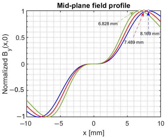
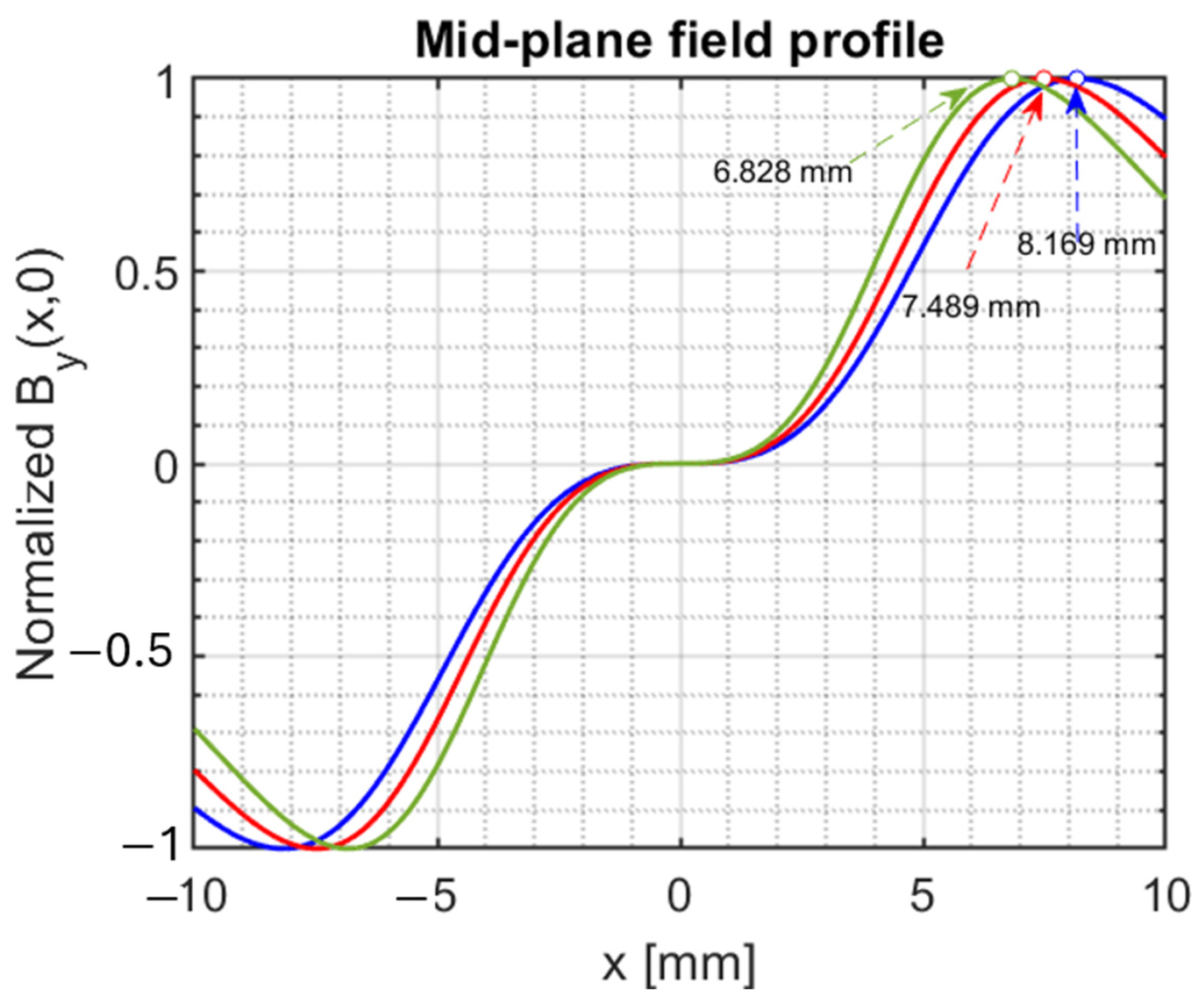
Relaxing the square-geometry constraint provides a modest but useful improvement in field placement. The symmetric reference geometry with is already close to an efficient 8-wire configuration. The relaxed-symmetry scan should therefore be viewed as an engineering refinement of the standard 8-wire concept, rather than a fundamentally new field configuration. Its primary benefit is to decouple the aperture-driven vertical coordinate from the horizontal field-shaping coordinate while preserving the single-supply on-axis cancellation condition. This additional freedom shifts inward, improving the field sampled at the injected-beam offset and reducing the required current. The achievable shift, however, remains limited by gradient-cancellation, wire-spacing, and chamber-clearance constraints. For the 8 mm vertical-gap baseline, corresponding to conductor-center spacing after including chamber and clearance constraints, the optimized solution gives (blue in Figure 5). Reducing the vertical aperture to 7 mm and 6 mm, corresponding to conductor spacings of and allows the conductors to move closer to the beam and shifts the field peak inward to approximately (red) and (green), respectively. Relative to the 8 mm gap baseline, these correspond to reductions of approximately 8% and 16% in . While this inward shift improves kick efficiency, it also reduces aperture and alignment margin. The final wire geometry must therefore be selected together with the injected-beam stay-clear analysis and mechanical tolerance requirements. All optimized configurations satisfy the single-supply gradient-cancellation condition with normalized residuals , confirming that the inward peak shift is obtained without compromising stored-beam transparency.
Figure 5.
Relaxed-symmetry 8-wire optimization with independent wire coordinates. Blue, red, and green correspond to the 8 mm, 7 mm, and 6 mm vertical-gap cases, respectively. Relaxing the square-geometry constraint shifts the off-axis field peak inward from 8.17 mm to 7.49 mm and 6.83 mm for reduced-gap configurations, improving kick efficiency while preserving on-axis field and gradient cancellation.
The relaxed-symmetry 8-wire family is therefore adopted as the practical optimization path. It preserves the key advantage of the 8-wire concept—stored-beam transparency from on-axis field and gradient cancellation—while providing additional freedom to improve the off-axis kick efficiency.
For completeness, Appendix A summarizes a generalized two-quartet analytical model that was explored early in this design study for independently powered inner and outer quartets. Although a dual-supply architecture is not adopted because strong mutual-inductive coupling complicates fast-pulsed implementation, the derivation remains useful for interpreting how superposition reshapes the off-axis field, broadens the near-axis flat region, and shifts the peak position.
4.2. Double-Dipole-Kicker Regime
The DDK regime is useful as a comparison because it can place the off-axis field peak closer to the beam axis. This is advantageous when the usable injected-beam offset is limited and efficiency must be maintained at smaller displacement. Like the 8-wire case, the DDK can be described by a normalized shape function, but with different symmetry and scaling.
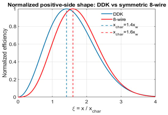
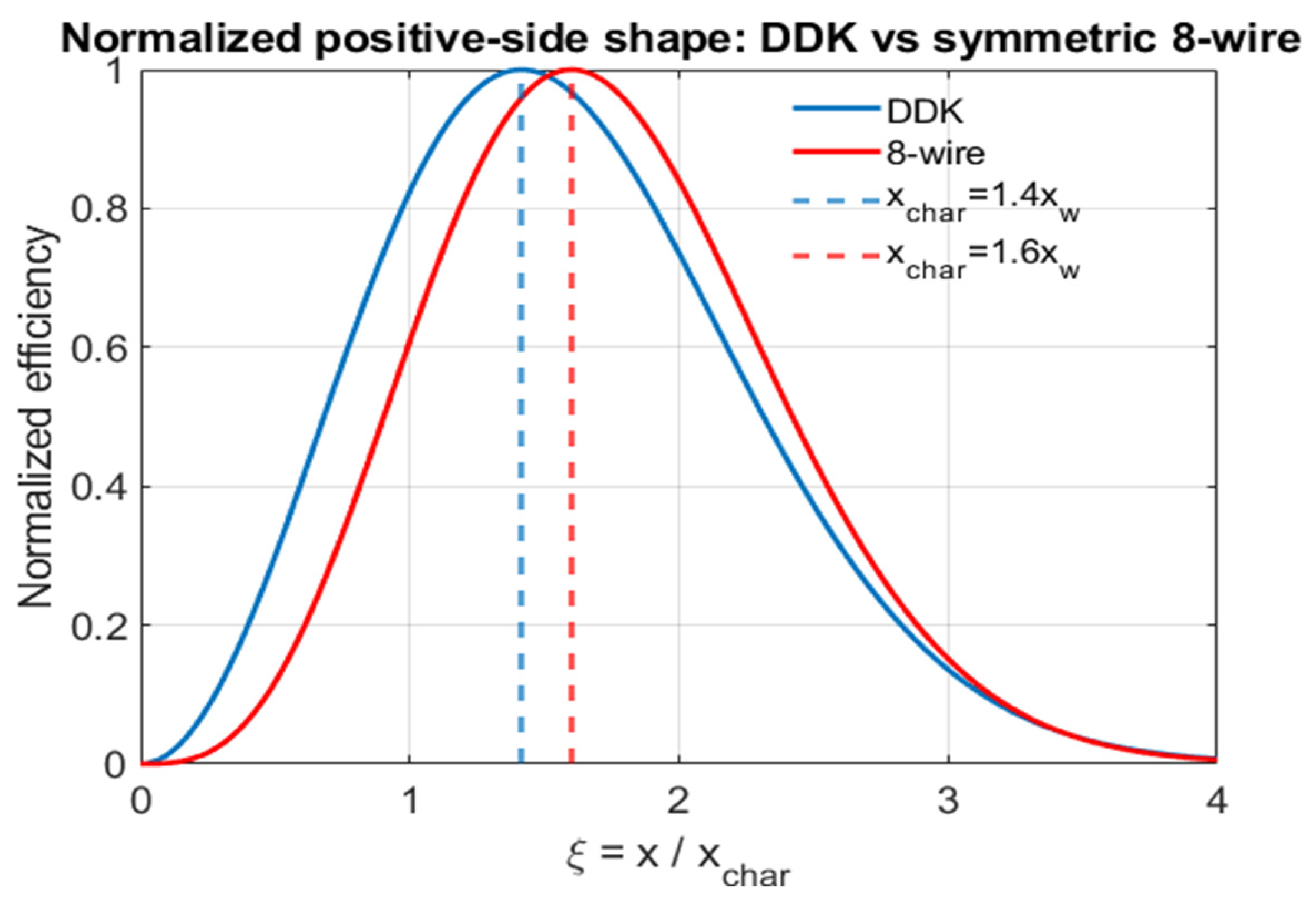
For comparable characteristic scale, the DDK field rises more rapidly away from the axis and reaches its peak closer to the stored-beam orbit,
compared with for the symmetric 8-wire reference geometry (Figure 6). Thus, the DDK naturally provides inward peak placement.
Figure 6.
Normalized field comparison between the DDK and symmetric 8-wire reference configurations with . The DDK rises more rapidly and peaks closer to the axis, near , whereas the symmetric 8-wire reference geometry exhibits a broader near-axis flat region and peaks near . The comparison highlights the trade-off between inward peak placement and stored-beam transparency. The relaxed-symmetry 8-wire optimization retains the robustness of the 8-wire family while partially recovering the inward peak-placement advantage.
This advantage comes with increased complexity. The DDK generally requires two independently controlled currents, and , to enforce on-axis cancellation and tune the field shape. While this provides flexibility, it complicates the pulsed-power implementation and increases sensitivity to current balance and timing mismatch. The DDK also has lower geometric symmetry than the 8-wire family, reducing the natural robustness of the near-axis transparent region. For this reason, the DDK is best viewed as an alternative when small injected-beam offset is the dominant constraint, rather than as the baseline solution for the NSLS-II prototype.
A 12-wire configuration can be viewed as an extension of the 8-wire geometry with an added 4-wire trim layer. As demonstrated at Sirius [22,23], this additional layer provides more field-shaping freedom and can be used for error compensation and fine optimization. For the present application, however, the added flexibility comes at the cost of increased geometric complexity, more demanding support structures, and more complicated excitation schemes. Because the relaxed-symmetry 8-wire geometry already provides sufficient peak-placement flexibility while preserving the robustness and simplicity of the 8-wire family, the incremental benefit of the 12-wire variant is limited for the NSLS-II prototype. The relaxed-symmetry 8-wire family therefore provides the most favorable balance between field quality, kick efficiency, mechanical robustness, and implementability.
5. Scaling Laws Connecting Optics to Hardware
The connection between beam dynamics and hardware is most clearly expressed through a small set of scaling relations that link injected-beam offset, wire geometry, magnet length, and chamber design directly to current, force, and thermal load.
5.1. Wire Geometry and Kicker Efficiency
For a fixed NLK location, the wire geometry sets the characteristic field scale and therefore the kicker efficiency. In the symmetric reference scaling, the chamber gap and wire diameter determine a single characteristic wire position. In the relaxed-symmetry design, the chamber gap primarily constrains the minimum vertical coordinate, while the horizontal coordinate remains available for field-shape optimization. This distinction is important because reducing the characteristic distance between the conductors increases the field strength at the injected beam position and lowers the required current. As an illustrative scaling example at ID2 downstream, an effective wire-position scale of 4.5 mm instead of 5.0 mm increases the field sampled at mm, reducing the current required for a 0.48 mrad kick from ∼600 A to ∼400 A.
Within the parameter range considered in this study, current reduction arises from the expanded feasible geometry and improved field scale, rather than from a direct prescription of the horizontal wire coordinate alone. The final geometry must still preserve mechanical robustness, aperture margin, and acceptable Lorentz force.
5.2. Scaling Relations for Current, Force, and Chamber Geometry
The required current is determined by the kick at the injected-beam position, making the injected offset a key design parameter rather than a passive outcome. A larger usable offset improves efficiency because the beam samples a stronger portion of the nonlinear field, although this advantage is limited by aperture constraints and by the need to avoid excessive field variation across the beam.
For a fixed integrated kick, increasing the magnet length reduces the required current approximately in inverse proportion to length. If the geometry is scaled consistently, the required voltage changes more weakly, so the pulsed-power demand does not scale directly with length. However, a longer magnet also has higher inductance and increased stored-beam-induced heating, making the choice a balance between electrical, thermal, and mechanical considerations.
For the prototype parameters considered here, the resulting current and inductance levels remain compatible with existing fast pulsed-power technologies. For the parameter range considered here, peak currents of a few hundred amperes and effective inductances at the microhenry level correspond to drive voltages in the kilovolt range for sub-microsecond rise times [24,25].
Electromagnetic force scales as and inversely with wire spacing, making current reduction particularly beneficial. For a fixed kick, any design choice that lowers the required current produces a disproportionately large reduction in force. For the NSLS-II candidate locations considered here, this scaling favors higher- locations combined with sufficient magnet length because the resulting reduction in current provides a substantial improvement in force margin.
The vacuum chamber and magnet geometry are tightly coupled. The chamber gap, required clearance, and wire diameter together determine the minimum feasible wire position, which sets the characteristic field scale and therefore the peak location and normalized efficiency sampled by the beam. The resulting design chain is direct: chamber gap → wire position → field scale → required current → force and pulsed-power burden.
5.3. Coating Thickness: RF Heating vs Field Attenuation Trade-Off
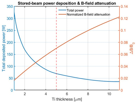
The conductive coating on the ceramic chamber introduces a coupled trade-off between stored-beam power deposition and magnetic field transmission. Increasing the coating thickness reduces resistive losses and lowers the deposited power but also increases attenuation of the NLK field.
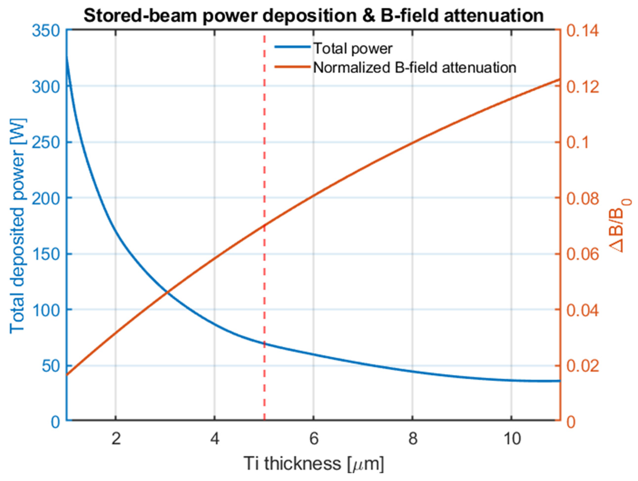
Figure 7 shows that power decreases rapidly with thickness at small values [26,27,28], while field attenuation increases more gradually. Beyond a few microns, the power reduction saturates, whereas attenuation continues to grow. This leads to a practical operating region in which a few-micron coating provides substantial thermal benefit with acceptable field loss. In the present design, a thickness of about 5 μm represents a reasonable compromise.
Figure 7.
Trade-off between stored-beam power deposition and magnetic-field attenuation as a function of titanium coating thickness. The calculation assumes a stored-beam current of 500 mA and the nominal NSLS-II fill pattern with 1200 filled buckets and a 120-bucket ion-clearing gap. The deposited power (left axis) decreases rapidly with increasing thickness, while the normalized field attenuation (right axis) increases more gradually. The vertical red dashed line indicates a representative design point near 5 μm, providing a balance between reduced RF heating and acceptable field attenuation.
Unlike a conventional dipole injection kicker, the NLK relies primarily on spatial transparency: the stored beam traverses the on-axis region where both the field and its first derivative are designed to vanish. Consequently, stored-beam perturbation is determined mainly by residual field and alignment errors rather than by precise pulse timing. Practical operation nevertheless requires synchronization of the pulse with the injected bunch train so that the injected beam samples the intended kick profile. For the approximately 5 μm titanium coating considered here, the expected effect on the pulsed field is primarily attenuation rather than substantial temporal distortion on the sub-microsecond timescale relevant to the present design.
6. Validation in the NSLS-II Case Study
The NSLS-II results serve as validation of the design framework rather than its primary motivation. The key requirement for NLK implementation is that the injected-beam first-turn trajectory be predictable and controllable with sufficient accuracy to define the beam offset at candidate NLK locations.
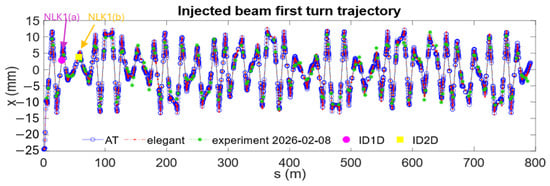
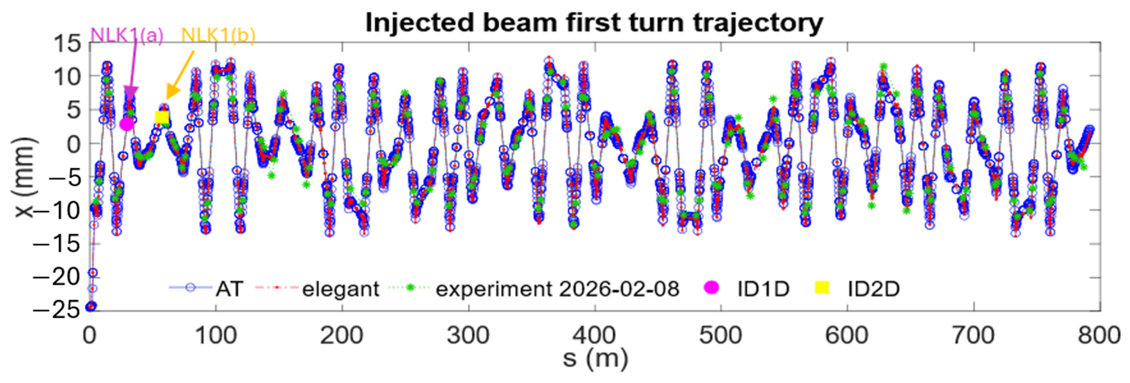
Figure 8 compares injected-beam first-turn trajectories obtained from AT [29], elegant, and beam-based measurements. The close agreement in both shape and amplitude demonstrates that the first-turn orbit is reliably reproduced across simulation and experiment. In particular, the measured and simulated beam positions at the candidate NLK locations agree to within about 0.6 mm and lie well within the available steering range, confirming that the predicted offsets used in the NLK design are robust.
Figure 8.
Comparison of injected-beam first-turn trajectories from AT (blue), elegant (red), and beam-based measurements (green). The agreement in both shape and amplitude demonstrates that the first-turn trajectory is consistently reproduced. The candidate NLK locations (ID1 downstream and ID2 downstream) are indicated, showing consistent beam offsets at these positions and validating the use of tracking-based predictions for NLK placement.
Kicker scans and beam-based studies further show that the injected beam can be reliably steered over the required offset range at these locations. Table 4 summarizes the measured offsets and the achievable tuning range, demonstrating that the available control authority is adequate to position the beam near the desired operating point of the NLK field profile, including the region close to the off-axis peak.
Table 4.
Measured and simulated beam positions at selected candidate NLK locations. Mean positions, rms beam sizes, and horizontal tuning range are obtained from measurements; simulated values are from first-turn trajectory tracking. The x range column denotes the demonstrated horizontal steering range obtained from first-turn kicker scans.
These results show that NLK implementation is not fundamentally limited by injection-trajectory reproducibility or control. The measured agreement and available tuning range demonstrate that the machine provides sufficient stability and steering flexibility to realize the predicted operating conditions.
7. Prototype Design Implications for NSLS-II
Applying the framework developed above to NSLS-II leads to a coupled design solution rather than a set of independent choices [24,25,30]. From beam-dynamics considerations, locations with higher are preferred because they increase kick efficiency, reduce the required current, and improve the mechanical-force margin. However, NLK placement is also constrained by the available physical aperture, particularly in the vertical plane, where the injected-beam stay-clear envelope must remain compatible with the finite chamber gap. Since sufficient vertical clearance is not uniformly available around the NSLS-II ring, the location choice cannot be made from optics considerations alone.
Unless otherwise noted, the stay-clear analysis and prototype parameters presented in this section correspond to the selected 6 mm full-gap baseline configuration. The 7 mm and 8 mm gap cases discussed earlier are retained as reference points for evaluating aperture, protection, and field-efficiency trade-offs.
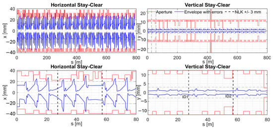
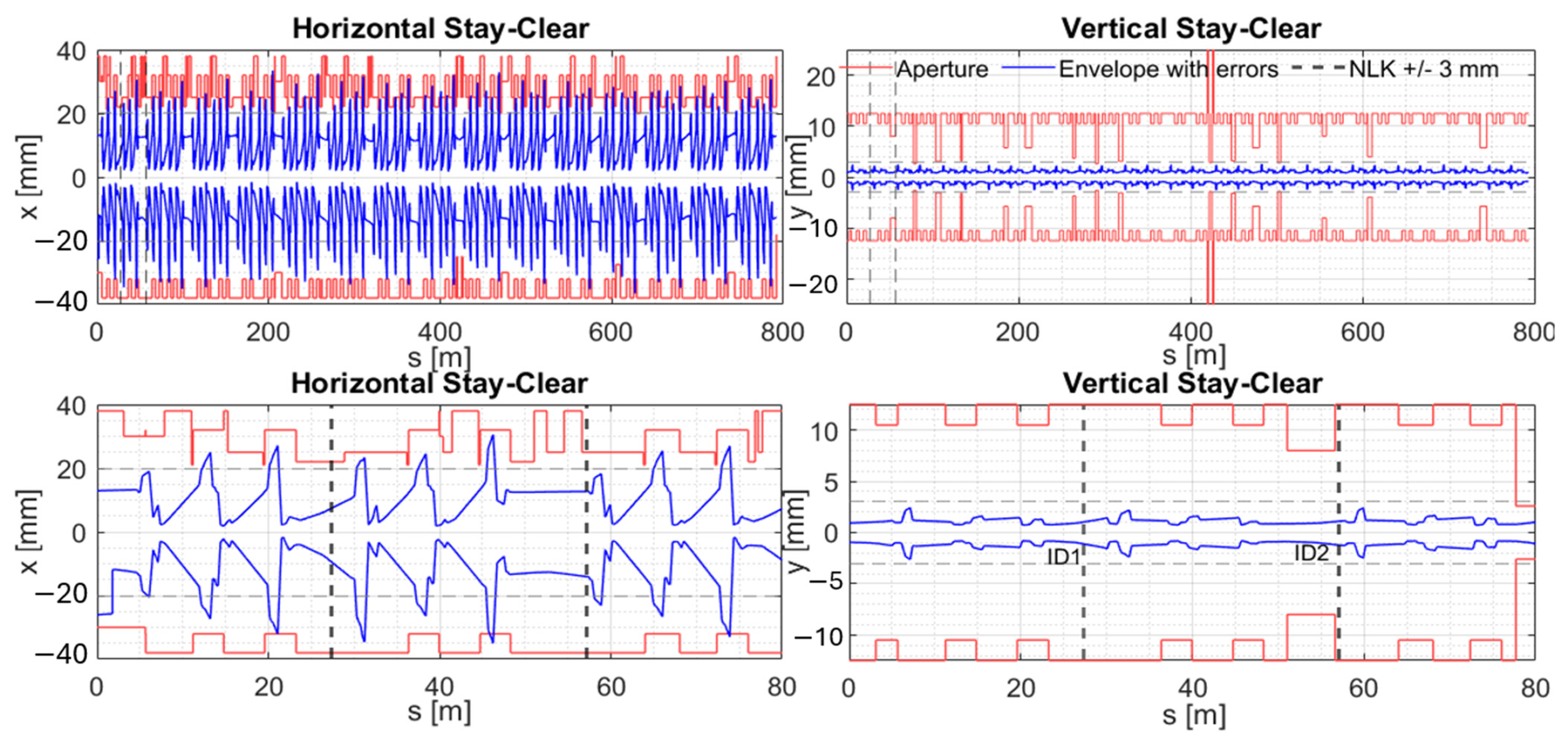
The aperture feasibility of candidate NLK locations was evaluated using multi-turn tracking of the injected beam. The simulated injected distribution used the booster extracted-beam parameters () , , , ), matched at the storage-ring injection point with () ) m, and was tracked for 40 turns. Here, and denote rms geometric emittance. Forty turns were chosen because the objective of this study is to evaluate the maximum injected-beam envelope during the early-turn injection transient. Any aperture limitation would occur within this period, whereas radiation damping acts on a much longer timescale and is therefore not relevant to this stay-clear assessment. Conservative injection errors were applied once as initial-condition offsets, using , , and , and subsequently propagated through multi-turn tracking without additional stochastic kicks. Here, denotes the intrinsic energy spread, while represents the injection energy offset. The stay-clear was defined using the 99.9% contour of the tracked distribution and compared with the element-by-element ring aperture, including the 6 mm full vertical NLK gap.
Under these assumptions, both ID1 and ID2 retain positive horizontal and vertical aperture margins, confirming that the NLK gap does not impose a limiting constraint within the evaluated ID-straight aperture model. Therefore, neither location is limited by the ring aperture nor by the NLK gap for the assumed injected-beam distribution and injection-error conditions. The vertical plane remains the more restrictive aperture constraint, but the available margin is sufficient at both candidate locations. This separates aperture feasibility from the final location choice: once both locations satisfy the stay-clear requirement, the comparison between ID1 and ID2 becomes primarily a trade-off between NLK performance margin and project-level integration constraints. The NLK-protection scraper settings were also checked with momentum-acceptance tracking. The accepted momentum range remains unchanged over the scanned interval [−4%, +4%], which is comparable to the RF acceptance of the NSLS-II storage ring. Within this operationally relevant range, the scraper does not become the limiting off-momentum aperture.
From the NLK performance perspective, ID2 remains favorable. Its larger beta function reduces the required kick strength and pulsed current, which in turn lowers the Lorentz-force load on the conductors and improves the pulsed-power margin. The larger injected-beam excursion and beam size at ID2 are accommodated within the available aperture in the tracking study. In addition, the injected-beam phase space can be further controlled through booster emittance-exchange optimization and transfer-line matching. Thus, if beam-dynamics performance and hardware margin are weighted most strongly, ID2 provides the more favorable NLK location. ID1, by contrast, may be preferred if installation constraints, integration risk, accessibility, or operational robustness dominate the final project decision. The final location selection should therefore be viewed as a system-level optimization rather than as a purely optics-driven or aperture-driven choice.
Figure 9 shows the injected-beam stay-clear envelope compared with the physical aperture for the candidate locations. The envelope remains within both the ring aperture and the 6 mm full vertical NLK gap at ID1 and ID2, confirming positive margin in both planes.
Figure 9.
Injected-beam stay-clear envelope from multi-turn tracking compared with the physical aperture at candidate NLK locations. Upper panels show the full ring, and lower panels show the local ID-region zoom. The NLK gap is indicated by dashed lines. Both ID1 and ID2 maintain positive aperture margin in both planes.
The principal parameters of the selected prototype configuration are summarized in Table 5, providing a compact reference for the final beam-dynamics, geometry, and pulsed-power design values.
Within the relaxed-symmetry 8-wire family, the prototype design balances mechanical robustness, field efficiency, and aperture compatibility. The initial symmetric configuration provides the reference scaling, but the optimized design treats the horizontal and vertical wire coordinates as independent variables. This additional freedom shifts the off-axis field peak inward, improving kick efficiency and reducing the required pulsed current. The improvement is strongest for smaller vertical gaps; however, reducing the gap also reduces aperture, alignment, and commissioning margin. The prototype design therefore requires a joint optimization of wire geometry, chamber aperture, and injected-beam stay-clear. Among the scanned configurations, the smaller-gap solutions provide better field efficiency, while the final choice must preserve positive aperture margin, sufficient wire spacing, acceptable Lorentz force, and manageable thermal load.
8. Conclusions
This work presents a quantitative design framework for nonlinear-kicker-assisted injection in ultralow-emittance storage rings under realistic machine constraints. For retrofit systems, the conventional four-kicker bump defines the injected trajectory, while one or more NLKs reduce the first-turn action. The action–angle formalism yields compact design rules: use the phase–offset compromise as the primary placement guide, account for the offset dependence of realistic cubic-like fields, favor sufficiently large horizontal , while accounting for finite-beam-size dilution and maintaining low dispersion, and place the first NLK as early as possible on the first turn.
Within this optics framework, candidate field configurations are evaluated, and the 8-wire NLK family emerges as the most practical solution. The symmetric geometry provides a useful analytical reference, while the relaxed-symmetry design enables independent optimization of horizontal and vertical wire positions. This additional freedom shifts the off-axis field peak inward, improving kick efficiency and reducing the required current while preserving stored-beam transparency through on-axis field and gradient cancellation.
The NSLS-II case study demonstrates that beam dynamics, aperture constraints, and hardware limitations form a coupled design problem. Multi-turn tracking confirms that the optimized NLK configuration maintains a positive stay-clear margin at candidate locations, showing that aperture is not the primary limiting factor under the assumed injected-beam and protection conditions and enabling selection based on performance and integration considerations. The resulting design reduces the required current and Lorentz-force load relative to less efficient geometries and locations, while maintaining pulsed-power requirements within existing technological capabilities.
More broadly, the present work shows that NLK-assisted injection can be treated as a coupled optics-and-hardware optimization problem rather than as a standalone kicker-design problem. The resulting framework provides a practical and reusable methodology for designing hybrid NLK injection systems in both retrofit upgrades and future diffraction-limited storage rings.
Author Contributions
Conceptualization, investigation, and formal analysis, X.Y.; writing—original draft preparation, X.Y.; Radia simulations, P.N. All authors contributed to manuscript review and editing. All authors have read and agreed to the published version of the manuscript.
Funding
This work was supported by Brookhaven National Laboratory Directed Research and Development Program. This manuscript has been authored by Brookhaven Science Associates under Contract No. DE-SC0012704 with the U.S. Department of Energy and Brookhaven National Laboratory LDRD 27721. The United States Government retains and the publisher, by accepting the article for publication, acknowledges that the United States Government retains a non-exclusive, paid-up, irrevocable, worldwide license to publish or reproduce the published form of this manuscript, or allow others to do so, for United States Government purposes.
Data Availability Statement
The datasets generated and analyzed during the current study are available from the corresponding author upon reasonable request.
Acknowledgments
The authors are grateful to V. Smaluk, M. Song, R. Todd, P. Palecek, T. Chiesa, and H. Dave for valuable discussions and technical assistance, and to A. Kahn for providing the power-deposition analysis code. Special thanks are extended to T. Shaftan for exceptionally valuable discussions, guidance, and continued support throughout the NLK injection project.
Conflicts of Interest
The authors declare no competing financial and non-financial interests in relation to the work described in this paper.
Appendix A
The following derivation is retained as an analytical reference to a generalized two-quartet, independently powered 8-wire concept. This architecture is not adopted as the baseline hardware in the present paper because it requires two high-current pulsed channels and introduces strong mutual-inductive coupling between the inner and outer quartets. It is included here because the mathematics remains useful for understanding how quartet superposition modifies the near-axis behavior and off-axis peak position.
Appendix A.1. Algebraic Simplification of the Four-Wire Field
Consider four wires located at
each carrying current along . Here, . Because each top–bottom pair has the same and the same , their contributions to are identical.
Contribution from the pair at , :
Contribution from the pair at , :
Summing all four wires:
Define
Then
For the numerator,
So
For the denominator,
Thus Equation (A2) becomes
Including the overall factor from Equation (A2),
which is the four-wire mid-plane field used as the building block of the generalized superposition model.
Appendix A.2. Critical Broad-Flat-Center Condition for the Generalized Two-Quartet Model
For a rectangular quartet, the linear coefficient is proportional to . For a square quartet, , this term vanishes and the leading field is cubic, as shown in Appendix A. Therefore, any additional broad-flat-center condition in a dual-supply two-quartet model corresponds to cancellation of higher-order terms, not to the basic on-axis field or gradient cancellation used in the single-supply design. Because the dual-supply architecture is not adopted here, the exact higher-order balance is not used in the prototype optimization.
References
- Einfeld, D.; Plesko, M.; Schaper, J. First multi-bend achromat lattice consideration. J. Synchrotron Radiat. 2014, 21, 856–861. [Google Scholar] [CrossRef] [Scilit] [PubMed]
- Borland, M.; Lindberg, R.; Berenc, T.; Sajaev, V.; Sun, Y. Lower emittance lattice for the Advanced Photon Source Upgrade using reverse bending magnets. In Proceedings of the North American Particle Accelerator Conference (NAPAC’16), Chicago, IL, USA, 9–14 October 2016; JACoW: Geneva, Switzerland, 2017; pp. 877–880. [Google Scholar]
- Raimondi, P.; Liuzzo, S. Toward a Diffraction-Limited Light Source. Phys. Rev. Accel. Beams 2023, 26, 021601. [Google Scholar] [CrossRef] [Scilit]
- Eriksson, M.; van der Veen, J.F.; Quitmann, C. Diffraction-limited storage rings—A window to the science of tomorrow. J. Synchrotron Radiat. 2014, 21, 837–842. [Google Scholar] [CrossRef] [Scilit] [PubMed]
- Sun, C.; Amstutz, P.; Hellert, T.; Leemann, S.C.; Steier, C.; Swenson, C.; Venturini, M. Optimizations of nonlinear kicker injection for synchrotron light sources. Phys. Rev. Accel. Beams 2020, 23, 010702. [Google Scholar] [CrossRef] [Scilit]
- Bartolini, R.; Abraham, C.; Apollonio, M.; Bailey, C.P.; Cox, M.P.; Day, A.; Fielder, R.T.; Hammond, N.P.; Heron, M.T.; Holdsworth, R.; et al. Double-double bend achromat cell upgrade at the Diamond Light Source: From design to commissioning. Phys. Rev. Accel. Beams 2018, 21, 050701. [Google Scholar] [CrossRef] [Scilit]
- Biasci, J.; Bouteille, J.; Carmignani, N.; Chavanne, J.; Coulon, D.; Dabin, Y.; Ewald, F.; Farvacque, L.; Goirand, L.; Hahn, M.; et al. A low emittance lattice for the ESRF. Synchrotron Radiat. News 2014, 27, 8–12. [Google Scholar] [CrossRef] [Scilit]
- Liu, L.; Resende, X.; Rodrigues, A.; de Sá, F. Injection Dynamics for Sirius Using a Nonlinear Kicker. In Proceedings of IPAC 2016; JACoW: Busan, Republic of Korea, 2016; pp. 3406–3408. [Google Scholar] [CrossRef] [Scilit]
- Leeman, S.C. Pulsed sextupole injection for Sweden’s new light source MAX IV. Phys. Rev. Spec. Top. Accel. Beams 2012, 15, 050705. [Google Scholar] [CrossRef] [Scilit]
- Danilov, V.; Nagaitsev, S. Nonlinear accelerator lattices with one and two analytic invariants. Phys. Rev. Spec. Top. Accel. Beams 2010, 13, 084002. [Google Scholar] [CrossRef] [Scilit]
- Kuske, P. Proposal for a transparent off-axis injection scheme for BESSY II. In Proceedings of the Workshop on Injection and Injection System (TWIIS), Berlin, Germany, 27–30 August 2017. [Google Scholar]
- Song, W.; Shang, L.; Shang, F.; Liu, W.; Sun, Z. A novel kind of nonlinear kicker for the Hefei Advanced Light Facility. Nucl. Instrum. Methods Phys. Res. A 2021, 990, 164986. [Google Scholar] [CrossRef] [Scilit]
- Steier, C.; Bohon, J.; Borra, S.; Chow, K.; Espino-Devine, C.; DiMasi, E.; Ganetis, G.; Hellert, T.; Johansson, M.; Joseph, J.; et al. Status of the ALS-U project to create a soft x-ray diffraction limited light source. J. Phys. Conf. Ser. 2025, 3010, 012046. [Google Scholar] [CrossRef] [Scilit]
- Song, W.B.; Liu, W.; Lu, Y.; Shang, F.L.; Shang, L.; Sun, Z.B. A New Nonlinear Kicker Design and Measurement. In Proceedings of the 10th International Particle Accelerator Conference (IPAC’19), Melbourne, Australia, 19–24 May 2019; Paper WEPMP017; JACoW: Geneva, Switzerland, 2019. [Google Scholar]
- Song, M.; Shaftan, T. Design study of a low emittance complex bend achromat lattice. Phys. Rev. Accel. Beams 2024, 27, 061601. [Google Scholar] [CrossRef] [Scilit]
- Takaki, H.; Nakamura, N.; Kobayashi, Y.; Harada, K.; Miyajima, T.; Ueda, A.; Nagahashi, S.; Shimada, M.; Obina, T.; Honda, T. Beam injection with a pulsed sextupole magnet in an electron storage ring. Phys. Rev. Spec. Top. Accel. Beams 2010, 13, 020705. [Google Scholar] [CrossRef] [Scilit]
- Wang, G.; Blum, E.; Cheng, W.; Choi, J.; Li, Y.; Seletskiy, S.; Shaftan, T.; Tian, Y.; Yang, L.; Yu, L.-H. NSLS-II Storage Ring Injection Optimization. In Proceedings of the 6th International Particle Accelerator Conference (IPAC15), Richmond, VA, USA, 3–8 May 2015. [Google Scholar]
- Benedetti, G.; Carlá, M.; Pont, M. A Double Dipole Kicker for Off and On-Axis Injection for ALBA-II. In Proceedings of the 13th International Particle Accelerator Conference (IPAC’22), Bangkok, Thailand, 12–17 June 2022; pp. 2701–2704. [Google Scholar]
- Wiedemann, H. Particle Accelerator Physics, 4th ed.; Springer: Cham, Switzerland, 2015. [Google Scholar]
- Jackson, J.D. Classical Electrodynamics, 3rd ed.; Wiley: New York, NY, USA, 1999. [Google Scholar]
- Chubar, O.; Elleaume, P.; Chavanne, J. A three-dimensional magnetostatics computer code for insertion devices. J. Synchrotron Radiat. 1998, 5, 481–484. [Google Scholar] [CrossRef] [Scilit] [PubMed]
- Quentino, J.V.; Alves, M.B.; de Sá, F.H. Emittance Exchange at SIRIUS Booster for Storage Ring Injection Improvement. In Proceedings of the 13th International Particle Accelerator Conference (IPAC’22), Bangkok, Thailand, 12–17 June 2022; pp. 2722–2724. [Google Scholar] [CrossRef]
- Resende, X.R.; Alves, M.B.; Liu, L.; Oliveira, A.C.S.; Quentino, J.V.; de Sá, F.H. SIRIUS Injection Optimization. In Proceedings of the 13th International Particle Accelerator Conference (IPAC’22), Bangkok, Thailand, 12–17 June 2022; pp. 2672–2674. [Google Scholar] [CrossRef]
- Pinjari, N.; Bindu, S. Compact Solid-State Marx Generator for Repetitive Applications. Eng. Technol. Appl. Sci. Res. 2020, 10, 6224–6230. [Google Scholar] [CrossRef] [Scilit]
- Alesini, D.; Guiducci, S.; Marcellini, F.; Raimondi, P. Design, test, and operation of new tapered stripline injection kickers for DAΦNE. Phys. Rev. Spec. Top. Accel. Beams 2010, 13, 111002. [Google Scholar]
- Khan, A.; Bassi, G.; Kosciuk, B.; Todd, R.; Smaluk, V.; Bacha, B.; Palecek, P.; Hetzel, C. Simulation and measurement of beam-induced heating of ceramic vacuum chambers. Phys. Rev. Spec. Top. Accel. Beams 2024, 27, 084501. [Google Scholar] [CrossRef] [Scilit]
- Vallgren, C.Y.; Arduini, G.; Bauche, J.; Calatroni, S.; Chiggiato, P.; Cornelis, K.; Pinto, P.C.; Henrist, B.; Métral, E.; Neupert, H.; et al. Amorphous Carbon Coatings for the Mitigation of Electron Cloud in the CERN SPS. Phys. Rev. Spec. Top. Accel. Beams 2011, 14, 071001. [Google Scholar] [CrossRef] [Scilit]
- Yao, M.L.; Suetsugu, Y.; Shibata, K.; Hisamatsu, H.; Ishibashi, T.; Terui, S.; Nishidono, T.; Chiba, H.; Sawahata, T.; Ishii, K. Secondary electron yields from thermal sprayed metal surfaces. In Proceedings of the 15th Annual Meeting of Particle Accelerator Society of Japan, Nagaoka, Japan, 7–10 August 2018; pp. 649–653. [Google Scholar]
- Terebilo, A. Accelerator Toolbox for MATLAB. SLAC-PUB-8732. 2001. Available online: https://s3.cern.ch/inspire-prod-files-3/3c93fc12dd6e5efef9ab4a47505f4431 (accessed on 20 February 2026).
- Yang, X.; Dave, H.; Li, Y.; N’Gotta, P.; Shaftan, T.; Smaluk, V.; Song, M.; Todd, R.; Wang, G. A compact top-off injection with cascaded nonlinear kickers for diffraction limited storage rings. In Proceedings of the North American Particle Accelerator Conference (NAPAC2025), Sacramento, CA, USA, 10–15 August 2025. [Google Scholar]

Disclaimer/Publisher’s Note: The statements, opinions and data contained in all publications are solely those of the individual author(s) and contributor(s) and not of MDPI and/or the editor(s). MDPI and/or the editor(s) disclaim responsibility for any injury to people or property resulting from any ideas, methods, instructions or products referred to in the content. |
© 2026 by the authors. Licensee MDPI, Basel, Switzerland. This article is an open access article distributed under the terms and conditions of the Creative Commons Attribution (CC BY) license.