


Abstract
Integrating the “programmable” characteristics of smart materials with 3D printing technology enables the integration of structural design and manufacturing, showing broad application prospects in flexible electronics, aerospace, biomedicine, and other fields. Magnetically controlled smart fluids are characterized by flexible solid–liquid conversion, high driving efficiency, and high safety. By harnessing the distinctive characteristics of this material, manufacturing and actuation approaches for intelligent structures can be further diversified. Inspired by the sol–gel transformation mechanism of protoplasm, this paper proposes a composite 3D printing method for magnetic and non-magnetic materials. A magnetically controllable binary suspension system with strong thixotropic properties was constructed, and its microscopic self-assembly structure was characterized. The yield behavior, linear viscoelastic properties, and thixotropic recovery performance of the magnetic thixotropic fluid (MTF) were investigated through steady and dynamic rheological measurements, and the optimal rheological parameters for printing were determined. A 3D printing platform with coordinated control of a magnetic field and a motion system was built to further study and optimize the printing process. The supporting characteristics of the MTF on a silicone film and the deformation of the printed composite structure under a gradient magnetic field were studied. The composite 3D printing and its application in soft robotics may provide new insights for space exploration, biomedicine, military reconnaissance, and many other fields.
1. Introduction
3D printing, also known as additive manufacturing, constructs objects layer by layer using materials such as metals [1], plastics [2] and ceramics [3] based on digital models. This technology enables the rapid and precise production of highly customized parts while reducing costs [4], making it widely applicable across industries including medical applications [5], mechanical engineering [6], electronics [7], and so on. However, a core challenge lies in achieving in situ phase transitions of the printing materials. To address this, various printing methods and hardware have been developed based on the specific phase transition mechanisms of different materials. For instance, thermoplastic materials, hot-melt materials, thixotropic materials, and photocurable materials are commonly used in fused deposition modeling (FDM) [8], selective laser sintering (SLS) [9], direct inkjet writing (DIW) [10], and stereo lithography appearance (SLA) [11], respectively.
Soft robots are a class of robots made from soft, elastic materials, offering excellent flexibility and adaptability that enable safe interaction with humans and the surrounding environment [12]. They are widely used in medical rehabilitation [13], surgical assistance [14], environment exploration [15], and disaster rescue [16]. Advances in 3D printing technology have significantly enhanced the fabrication of soft robots [17]. For instance, DIW, known for its simplicity and compatibility with various materials, has become an ideal method for soft robot manufacturing [18]. However, a key challenge remains: traditional 3D printing materials often lack the low modulus, high flexibility, and reversible phase transition required for soft robotics. Consequently, developing new printing materials to better meet these functional demands has become a prominent area of research.
4D printing builds upon 3D printing by introducing smart materials that respond to external stimuli, thereby adding the dimension of time [19]. Marco et al. [20] categorize 4D printing transformations into two types: unidirectional and bidirectional. In unidirectional 4D printing, the shape change remains even after the stimulus is removed, while bidirectional 4D printing allows for reversible transformations between two shapes under the influence of two alternating stimuli. Current 4D printing technologies primarily focus on the response of cured materials to external stimuli, often overlooking the regulation of liquid–solid reversible phase transitions. Magnetically controlled smart fluids can achieve controlled gel–sol transitions under the influence of a magnetic field [21]. By combining this characteristic with the DIW printing approach, we have creatively realized 3D printing of soft material composites based on sol–gel transition in additive manufacturing. Unlike traditional 3D printing, our new approach enables post-printing adjustment of the material’s rheological state, allowing the printed structure—either as a whole or in selected parts—to flexibly switch between solid and liquid phases, thus constituting a unique form of 4D printing.
Soft-bodied robots fabricated using 3D/4D printing with polymer-based smart materials are often limited by their high Young’s modulus, which makes it difficult to achieve highly flexible bionic locomotion. The most biomimetic form of soft-body motion is fluid flow. For instance, NASA proposed a conceptual design of a smart-fluid-driven soft robot for planetary exploration, while an amoeboid soft robot based on magnetically controlled smart fluids has also been developed [22]. This robot encapsulates a magnetically controlled smart fluid inside a polymer film; by modulating the internal magnetic field distribution, it drives the flow of the smart fluid, enabling the robot to adapt to complex exoplanet environments.
Existing technologies face challenges in achieving precise and integrated fabrication of single-cell-like robotic structures, and magnetically controlled phase-change reversible 3D printing technology offers an innovative solution to this problem [23,24,25,26]. On the one hand, the cured magnetically controlled smart fluid can provide effective support for printing elastic thin-film structures during the composite printing process; on the other hand, the molded smart fluid can serve as the driving medium of the soft structure. By regulating both the flow direction and the solid–liquid transition of the smart fluid, a design mode for soft-body intelligent structures that integrates manufacturing and actuation can be realized.
Ferrofluids (FFs) and magnetorheological fluids (MRFs) are two typical magnetically controlled smart fluids whose rheological properties change significantly under an external magnetic field. In FFs, the magnetic dipole force of nanoparticles is comparable to thermal Brownian force, and its viscosity increases gradually under a magnetic field while retaining a degree of fluidity [27]. Thus, FFs cannot be cured during printing. In contrast, the magnetic interaction between micron-sized particles in MRFs is much stronger than thermal Brownian motion. When a magnetic field is applied, these particles rapidly form chain or network structures, resulting in considerable yield stress [28]. The viscosity of MRFs increases instantaneously by several orders of magnitude. However, due to its lack of thixotropy, MRFs under a magnetic field cannot be extruded smoothly through a printing nozzle.
To overcome the limitations of FFs and MRFs in 3D printing, this paper proposes a novel magnetically controlled smart material composed of a bentonite/nano-magnetic particle binary suspension system, referred to as magnetic thixotropic fluid (MTF). Owing to its excellent shear-thinning and thixotropic behavior, along with effective magneto-rheological control, MTF is suitable for phase-change reversible 3D printing. Through an in-depth investigation into its rheological properties and microscopic mechanisms, we propose a magnetically controlled sol–gel transition-based composite 3D printing strategy and construct a dedicated 3D printing platform integrated with a customized extrusion module. By comparing printed filament cross-sections, grid patterns, and cylindrical structures under different conditions, we have optimized the 3D printing process based on the magnetically controlled thixotropy of the material. Using a multi-material printing strategy, we fabricated a deformable smart structure. This composite structure demonstrates precisely controllable deformation patterns in a gradient magnetic field environment. The composite DIW 3D printing technology presented in this paper holds significant application potential in areas such as flexible wearables, military reconnaissance, and biomedicine.
2. Preparation and Microstructural Characterization of MTF
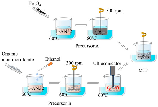
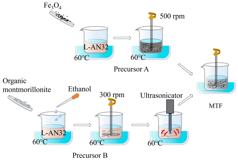
MTF consists of three main components: a carrier liquid, magnetic nanoparticles, and organic montmorillonite. The process for preparing MTF is illustrated in Figure 1. The Fe3O4 magnetic nanoparticles were added to the L-AN32 machine oil at 60 °C and stirred continuously at 500 rpm for 1 h, resulting in a solid phase volume fraction of 16% for precursor A. For precursor B, organic montmorillonite and a small amount of 95% ethanol were added to the L-AN32 machine oil. This mixture was stirred at 300 rpm for 1 h, followed by ultrasonication for 30 min. Under the combined effects of polar activation and physical shear, the organic montmorillonite was decomposed into monolayers, forming a three-dimensional lattice structure within the carrier liquid. The Fe3O4 suspension (precursor A) and organic montmorillonite suspension (precursor B) were mixed in a 1:1 volume ratio. This mixture was stirred continuously for 30 min. The “house of cards” structure formed by organic montmorillonite effectively resists the sedimentation of magnetic nanoparticles, resulting in MTF with excellent stability. The raw materials used in the preparation of MTF are listed in Table 1. Two different MTF samples with varying proportions were prepared, and their specific components are shown in Table 2.
Figure 1.
The preparation process of magnetic thixotropic fluid.
Table 1.
The raw materials for magnetic thixotropic fluid.
Table 2.
Specific proportions of components in magnetic thixotropic fluids.
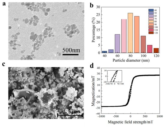
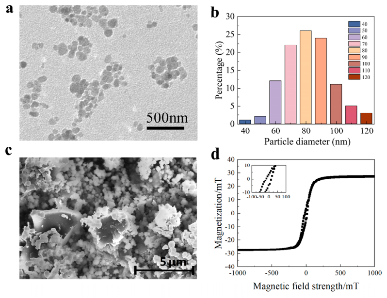
Transmission electron microscopy (JEM2010, JEOL, Tokyo, Japan) was used to observe the Fe3O4 particles, with a representative TEM image shown in Figure 2a. Based on the TEM images, the particle size distribution was analyzed, as depicted in Figure 2b. The average particle size of the Fe3O4 particles is 82 nm, with 96% of the particles falling within the range of 60 nm to 100 nm, indicating a relatively uniform size distribution. A scanning electron microscope (FEI Quanta200, FEI, Hillsboro, OR, USA) was employed to examine the microstructure of the MTF, as shown in Figure 2c. SEM imaging indicates that both Fe3O4 particles and exfoliated montmorillonite are well dispersed in the carrier liquid, maintaining distinct boundaries. This uniform dispersion without agglomeration is critical to the material’s favorable thixotropy, supporting its good fluidity and reversible phase transition characteristics. A vibrating sample magnetometer (EZ8, MicroSense, Lowell, MA, USA) was used to measure the magnetization of the MTF, with the results displayed in Figure 2d. The results indicate that MTF exhibits superparamagnetism, with a saturation magnetization of approximately 28.6 mT, demonstrating the MTF’s strong magnetic response performance.
Figure 2.
(a) TEM images of Fe3O4 particles. (b) Histogram of Fe3O4 particle size distribution. (c) SEM images of magnetic controlled thixotropic materials. (d) Two types of MTF hysteresis loop test results.
3. Printing Device and Process
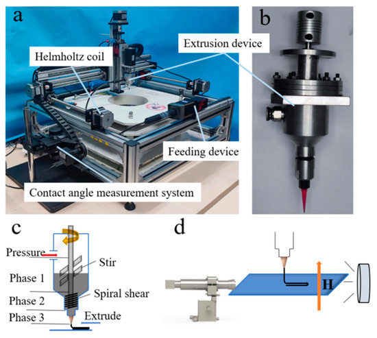
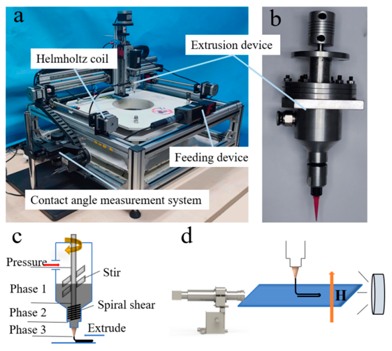
The successful 3D printing of MTF depends primarily on two key processes: precise extrusion and rapid solidification under a magnetic field. To achieve these goals, we developed a direct-write magnetic control 3D printing device, as shown in Figure 3a. The control system manages the entire process of the device, with a PLC (programmable logic controller) regulating the drive module, extrusion module, magnetic field module and recording module. The PLC is connected to a LabVIEW platform and can be controlled via custom software. Precise extrusion relies on the extrusion head, as illustrated in Figure 3b. The extrusion head simultaneously controls both the extruded amount and the rheological state of the material, using homogenization stirring and screw extrusion. In Figure 3c, the rotor generates a strong radial shear stress, breaking down the structures formed by magnetic nanoparticles and organic montmorillonite through intense shear forces. This process ensures uniformity in MTF and induces significant shear thinning, enabling the smooth extrusion of the MTF. A magnetic field application device provides a uniform magnetic field environment using Helmholtz coils. Additionally, an observation and recording device is integrated to monitor the printed structure’s shape through a contact angle measurement system, as shown in Figure 3d. This system recorded and analyzed the shape parameters of the MTF under various magnetic field conditions, providing insights into the material’s behavior and the forces acting on the printed lines. The analysis helped to determine the optimal MTF samples and magnetic field strengths suitable for high-quality printing. The detailed analysis panel is given in Section 5.
Figure 3.
Direct-write magnetic control 3D printing device. (a) Photograph of the 3D printing device. (b) Photograph of the extrusion head. (c) Schematic diagram of three-stage extrusion head’s structure. (d) Schematic diagram of the contact angle measurement system.
4. Rheological Behaviors of MTF
4.1. Shear-Thinning Property
The rheological properties of MTFs were tested using a rotational rheometer (Anton Paar MCR302, Anton Paar, Graz, Austria) equipped with an MRD170 magnetic field generator module. The measurements were conducted with a conical rotor of 20 mm diameter and a test gap of 0.084 mm.
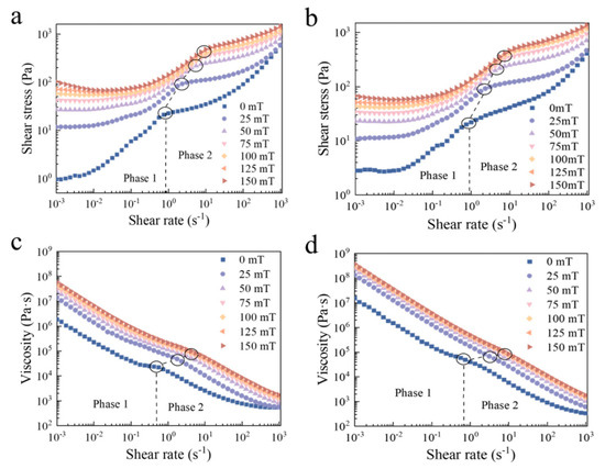
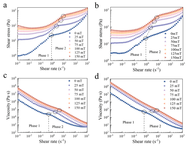
From the flow curves of the two MTF samples, shown in Figure 4a,b, two distinct stages of shear thinning are observed. In the first stage, under relatively low shear rates, the “house of cards” structure formed by montmorillonite laminates gradually breaks down (phase 1). As the system approaches the transition between the first and second stage, most of the “house of cards” structure is fully destroyed, while the Fe3O4 particle agglomerates remain intact, generating viscous effects in response to the flow field. As the shear rate increases, the agglomerate structure also disintegrates, leading to a second phase of pronounced shear thinning [29]. Upon the application of a magnetic field, the transition point between these two phases shifts to higher shear rates, indicating that the magnetic field induces the alignment of Fe3O4 particles along the field direction, forming a more solid and stable structure. This alignment enhances the resistance of the MTFs to the shear forces. The viscosity curves of both MTF samples, as depicted in Figure 4c,d, also display two distinct shear-thinning phases. Due to the higher concentration of Bentone SD-2 in sample 2 (composition detailed in Table 2), its viscosity is higher than that of sample 1. In both samples, as shown in Figure 4a–d, the shear stress and viscosity increase with the magnetic field strength. Once the magnetic field strength reaches 75 mT, further increases in field strength lead to minimal changes in both shear stress and viscosity. This indicates that the MTFs approach saturation magnetization at 75 mT, and the magnetic particle alignment reaches its most stable configuration.
Figure 4.
Shear-thinning characteristics of two types of MTF samples. (a) Relationship between shear rate and shear stress of sample 1. (b) Relationship between shear rate and shear stress of sample 2. (c) Relationship between shear rate and viscosity of sample 1. (d) Relationship between shear rate and viscosity of sample 2.
4.2. Nonlinear Viscoelastic Property
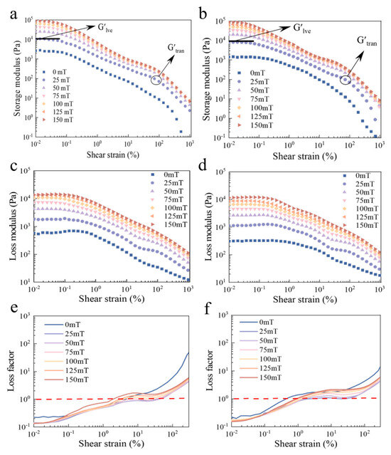
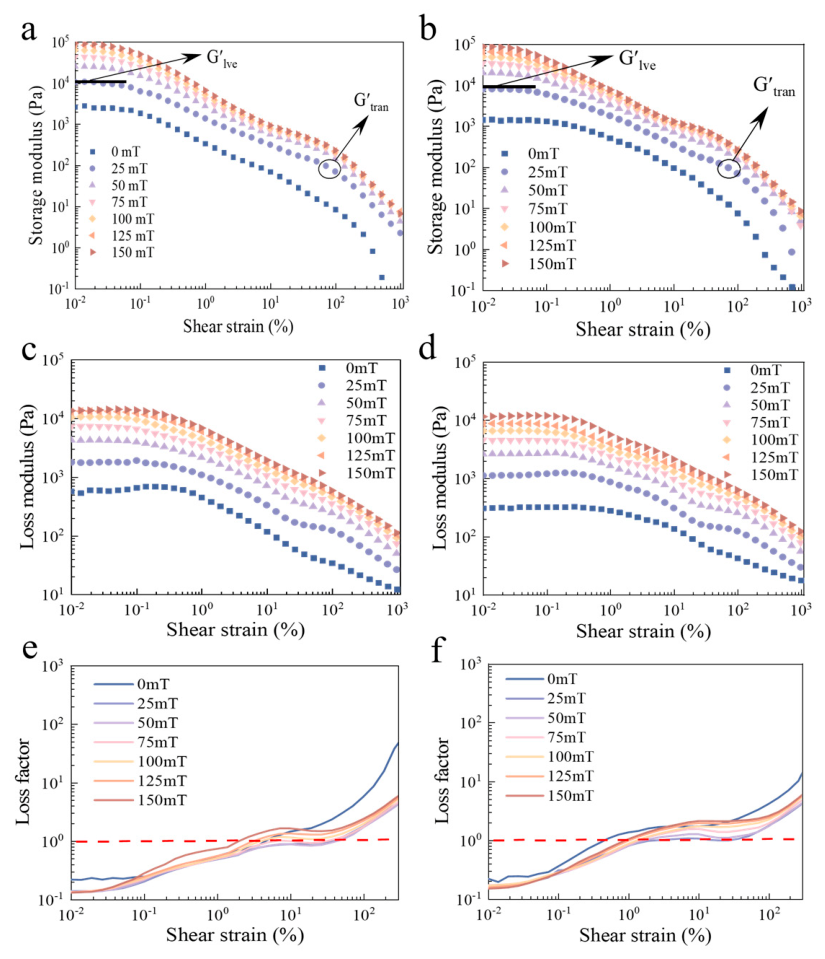
To quantitatively assess the strength of the microstructures in MTFs, amplitude sweep tests were performed on both MTF samples. The plots of storage modulus (G′) and loss modulus (G″) versus shear strain for the two MTFs are shown in Figure 5.
Figure 5.
Nonlinear viscoelastic properties of two MTF samples. (a) Relationship between shear strain and storage modulus of sample 1. (b) Relationship between shear strain and storage modulus of sample 2. (c) Relationship between shear strain and loss modulus of sample 1. (d) Relationship between shear strain and loss modulus of sample 2. (e) Relationship between shear strain and loss factor of sample 1. (f) Relationship between shear strain and loss factor of sample 2.
From Figure 5a,b, it is evident that within the shear strain range of 0.01% to 0.1%, the MTFs remain in the linear viscoelastic zone (LVE), where the storage modulus (G′) is not affected by the shear strain change. As the shear strain increases from 0.1% to 10%, a sharp decline in G′ is observed, signaling the material’s yield point. Between 10% and 100% shear strain, the decrease in G′ slows and eventually reaches a plateau. Beyond 100% shear strain, the storage modulus drops sharply again, a phenomenon referred to as secondary yielding [19]. In the absence of a magnetic field, the secondary yielding effect is minimal, but as the magnetic field strength increases, the effect becomes more pronounced. The first yielding corresponds to the breakdown of the “house of cards” structure formed by montmorillonite laminates, while the second yielding reflects the collapse of the structure formed by magnetic nanoparticles. The strong magnetic dipole interactions and dense packing of magnetic nanoparticles enable the structure to withstand larger shear strain, and the second yielding occurs at higher shear strain under increased magnetic field strength. The energy storage moduli associated with the first and second yielding are denoted as G′lve and G′tran, respectively. The magnitude of G′tran represents the structural integrity of the MTF during the printing process. Notably, under a magnetic field of 25 mT, the G′tran for sample 1 is 121 Pa, which is higher than that of sample 2, at 88 Pa, indicating that sample 1 possesses superior self-supporting strength.
As the shear strain increases, the loss factor (tan θ) rises, indicating a transition from an elastic to a viscous state. Figure 5c,d show that the loss modulus (G″) increases with magnetic field strength, suggesting a more pronounced viscous response as the magnetic field intensifies. In Figure 5e,f, the overall range of tan θ for sample 2 is smaller than that of sample 1. For example, under a magnetic field of 25 mT, the loss factor of sample 1 increases from 0.484 to 1.77 as the shear strain varies from 1% to 100%, while for sample 2, it increases from 0.792 to 1.74. The larger variation in the loss factor of sample 1 compared to sample 2 indicates that sol–gel transition becomes more difficult as the volume fraction of Bentone increases.
4.3. Thixotropic Recovery Characteristic
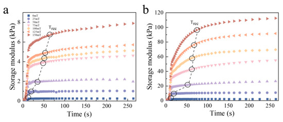
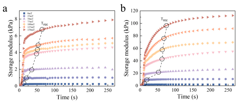
The thixotropic recovery process plays an important role in the formation of uniform filaments when the material flows out of the print nozzle. Within the MTF, magnetic nanoparticles and organic montmorillonite gradually form anisotropic microstructures of different scales under the influence of a magnetic field. Over time, these internal structures evolve toward equilibrium, contributing to the MTFs’ strong thixotropic recovery properties at the macroscopic level. Before conducting the thixotropic recovery test, a shear rate of 1000 s−1 was applied for at least 5 min to ensure that the internal structures in the samples were fully destroyed. The magnetic response of MTFs is highly rapid, as the magnetic nanoparticles quicky align to form anisotropic structures. As a result, the thixotropic recovery curve of MTFs can be divided into two distinct stages, as shown in Figure 6a,b. In the initial stage, the Fe3O4 rapidly forms columnar structures under the magnetic field, leading to a sharp increase in storage modulus G′ on the thixotropic recovery curve. In the subsequent, longer time range, Bentone forms a “house of cards” structure between the columnar structures created by Fe3O4. During this phase, the Fe3O4/Bentone binary dispersion system undergoes further relaxation due to both magnetic and non-magnetic interactions, eventually reaching equilibrium. This gradual relaxation corresponds to the slower rise in G′ over time on the thixotropic recovery curve. In the early phase of recovery, the sample 2 curve shows a more gradual upward trend compared to sample 1. This is attributed to the higher volume fraction of bentonite in sample 2, which generates greater resistance to the formation of the Fe3O4 anisotropic structures. Since the thixotropic recovery speed directly impacts the selection of the extrusion head’s movement speed during the printing process, a quantitative parameter is needed to evaluate recovery performance. The critical recovery time, Trec, is defined as the time required for the energy storage modulus to reach 85% of its stabilized value. The critical recovery time of sample 2 is longer than that of sample 1 at various magnetic field strengths. Under a magnetic field of 150 mT, the Trec of sample 1 is 62.7 s, while that of sample 2 is 73.8 s. The critical recovery time for both MTF samples increases with the magnetic field strength, indicating that the composite microstructures formed through the interaction of magnetic and non-magnetic components become more stable and efficient as the magnetic field intensifies. These composite structures, being more complex and anisotropic, require longer relaxation time under a stronger magnetic field.
Figure 6.
Thixotropic recovery characteristics of two MTF samples. (a) Relationship between recovery time and storage modulus for sample 1. (b) Relationship between recovery time and storage modulus for sample 2.
5. Printability and Forming Quality Assessment of MTF
5.1. Modulation of the Cross-Sectional Shape of MTF Filaments
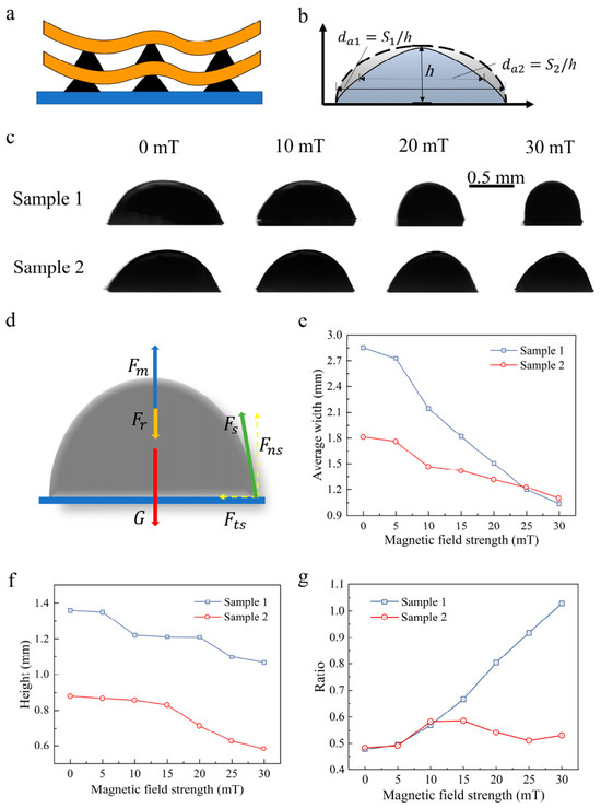
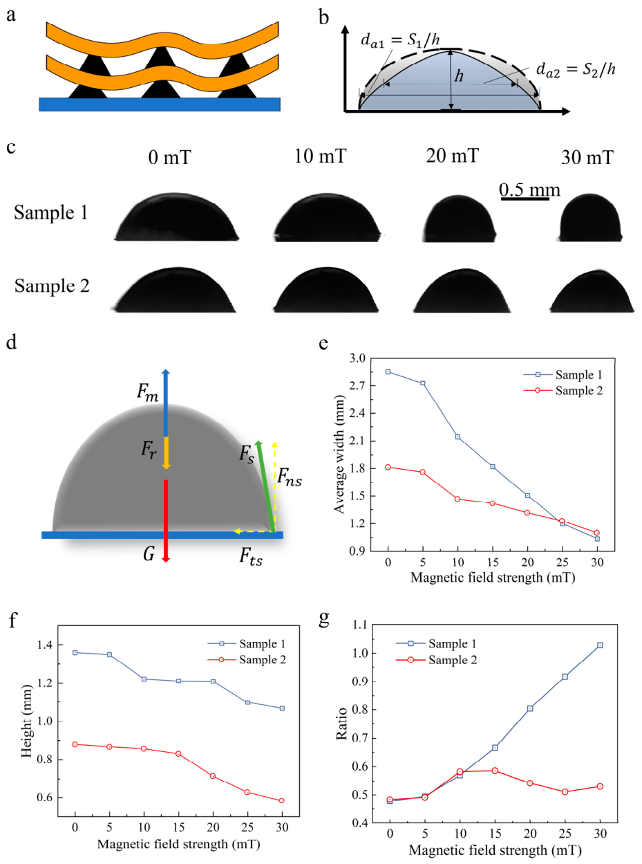
Extruding continuous filaments through the nozzle is fundamental for successful printing of gel-like materials [30]. A custom-built 3D printing platform was used to optimize the printing parameters, including extrusion pressure and printing speed, under a magnetic field ranging from 0 to 30 mT. This range was chosen because the viscosity rises steeply within it, reaching over 65% of its saturation value at 30 mT and increasing by approximately an order of magnitude compared to the zero-field state, whereas higher fields would require excessively bulky coils incompatible with the printing head. Based on the shear-thinning behavior of MTFs, the optimal printing head speed was determined to be 5 mm/s, with a material flow rate of 15 mL/s. To further investigate the effect of magnetic field on the MTF printing quality, the cross-sectional shape of the extruded filaments was analyzed using a contact angle measurement system. Cross-section shape is critical in direct ink writing (DIW) printing, as the printed filament must support its own weight and the weight of subsequent layers. The strength and shape of the filament’s cross-section determine whether complex structures can be successfully fabricated. When filaments from upper layers cross those from lower layers, the upper filament may experience shape collapse and bulging due to the internal flow of uncured material. This is more pronounced when the cross-sectional shape of the lower layer is triangular, as shown in Figure 7a. For a given filament height, a larger average width da indicates a fuller cross-sectional shape, as shown in Figure 7b. The ratio of height to average width R describes the three-dimensionality of the cross-section, providing a useful metric for evaluating the performance of the printed filament. In Figure 7c, the cross-sectional shapes of sample 1 and 2 filaments change significantly under varying magnetic field strengths. As the magnetic field strength increased from 0 to 30 mT, the height of sample 1 remained relatively constant, while the width decreased significantly, transitioning the filament’s shape from a bow-like structure to a combination of rectangular and bow shapes. In contrast, both the height and width of sample 2 decreased, with a more pronounced change in width, leading to a larger centroid angle of the bow arc. During filament magnetization, internal material flow occurred under the joint action of magnetic lifting force Fm, surface tension Fs and gravity G, as shown in Figure 7d. This internal flow generated viscous resistance Fr, which initially increased with shear rate but eventually reached equilibrium. The final cross-sectional shape of the MTF filament is thus determined by both the external magnetic field strength and the material’s internal rheological properties.
Figure 7.
Schematic of filament shape collapse and bulging. (a) Schematic of filament shape collapse and bulging. (b) Definition of cross-sectional parameters. (c) Cross-sectional shape evolution of samples 1 and 2 under varying magnetic fields. (d) Force analysis and internal flow mechanism within a magnetized filament. (e) Average width of MTF filaments as a function of magnetic field strength. (f) Height of MTF filaments as a function of magnetic field strength. (g) Aspect ratio of MTF filaments as a function of magnetic field strength.
As shown in Figure 7e,f, the average width and height of both MTF samples decreased as the magnetic field strength increased, indicating a reduction in the cross-sectional area of the printed filament. This suggested that higher-resolution printing can be achieved by increasing the magnetic field strength. The reduction in extrusion volume was attributed to the strong magnetorheological effect at the nozzle under the magnetic field, which significantly increased the MTFs’ viscosity. In Figure 7g, the ratio R of sample 1 increased sharply with increasing magnetic field strength, whereas the ratio R of sample 2 increased more gradually. Specifically, as the magnetic field increased from 0 to 30 mT, the ratio R of sample 1 rose from 0.43 to 1.2, while that of sample 2 increased from 0.41 to 0.55. These results indicated that sample 1 exhibits a more three-dimensional cross-sectional shape. The extruded MTF’s shape changed dynamically under the influence of the magnetic lifting force and gravity. The speed and duration of these changes were related to the MTF’s thixotropic properties. When the columnar and network structures formed inside the extruded MTF, the material developed a high yield stress, which was reflected in a high internal viscous resistance. Consequently, the height of the cross-section was no longer elevated. Due to the higher organic montmorillonite content in sample 2, it reached internal mechanical equilibrium more quickly, leading to a faster stabilization of the printed filament’s shape. The normal flow within the filament under the magnetic field was concentrated in the upper portion due to the lower shear rate exerted by the moving print head at the filament’s base. This caused a decrease in cross-section saturation as the magnetic field increased. Based on the results of the above study, the magnetic field had a more pronounced effect on the shape regulation of sample 1. Therefore, a magnetic field strength of 30 mT was selected, and sample 1 was chosen for the further printing-related experiments.
5.2. Optimization of Printing Speed Based on Curing Kinetics
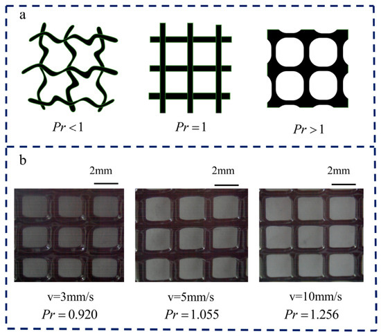
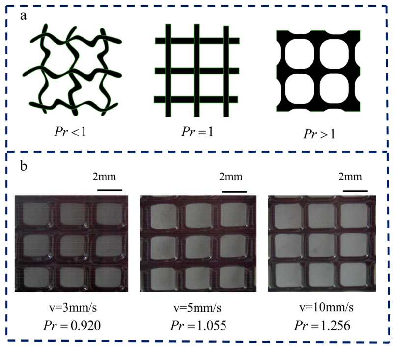
The curing of the printed material under a magnetic field is a thixotropic process. For successful stacking of multiple layers, selecting the appropriate printing speed based on the curing rate of MTFs under the magnetic field is crucial. Following the investigation of the magnetic field effect on the MTF cross-sectional shape, a grid pattern with double-layer, crossing filaments was selected to examine the MTFs’ thixotropic recovery properties during the printing process, as shown in Figure 8.
Figure 8.
Investigation of MTF curing status at different printing speeds. (a) Schematic diagram of shapes corresponding to different printing curing parameters. (b) Comparison diagram of cross-pattern structure printed with different printing speeds.
The raster pore shapes vary with different printing speeds. By quantitatively analyzing these pore shapes, the degree of thixotropic recovery of the MTF at different printing speeds can be assessed. A square pore shape indicates that the sample’s thixotropic recovery is well matched to the chosen printing speed. If the pores are close to a circular shape, it suggests that the printed filaments have fused together, implying insufficient thixotropic recovery during extrusion. Conversely, an irregular pore shape indicates that the filaments recovered too quickly, preventing continuous curing during extrusion flow.
To qualitatively assess the thixotropic recovery behavior of the MTF during printing, the curing parameter Pr was introduced for comparison, calculated using the following formula [31]:
where L is the internal perimeter of the pore, and A is the pore area.
When Pr < 1, it represents undercuring, hindering proper formation of the designed structure. When Pr = 1, the optimal curing state is achieved, resulting in a standard square pore shape. Conversely, when Pr > 1, it indicates overcuring, as illustrated in Figure 8a. The statistics analysis of the Pr value for sample 1 under different printing speeds is shown in Figure 8b At a printing speed of 5 mm/s, the optimal printing result is obtained, with Pr close to 1, indicating near-ideal curing. At a slower printing speed of 3 mm/s, the Pr value drops to approximately 0.92, signaling undercuring. In contrast, at a higher printing speed of 10 mm/s, the printing time interval between different layers is insufficient, leading to inadequate thixotropic recovery of the MTF within the grid pattern. As a result, the filaments converge in the pattern due to insufficient recovery time, with the Pr value increasing to 1.256, indicating overcuring.
5.3. Self-Supporting Capability
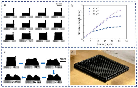
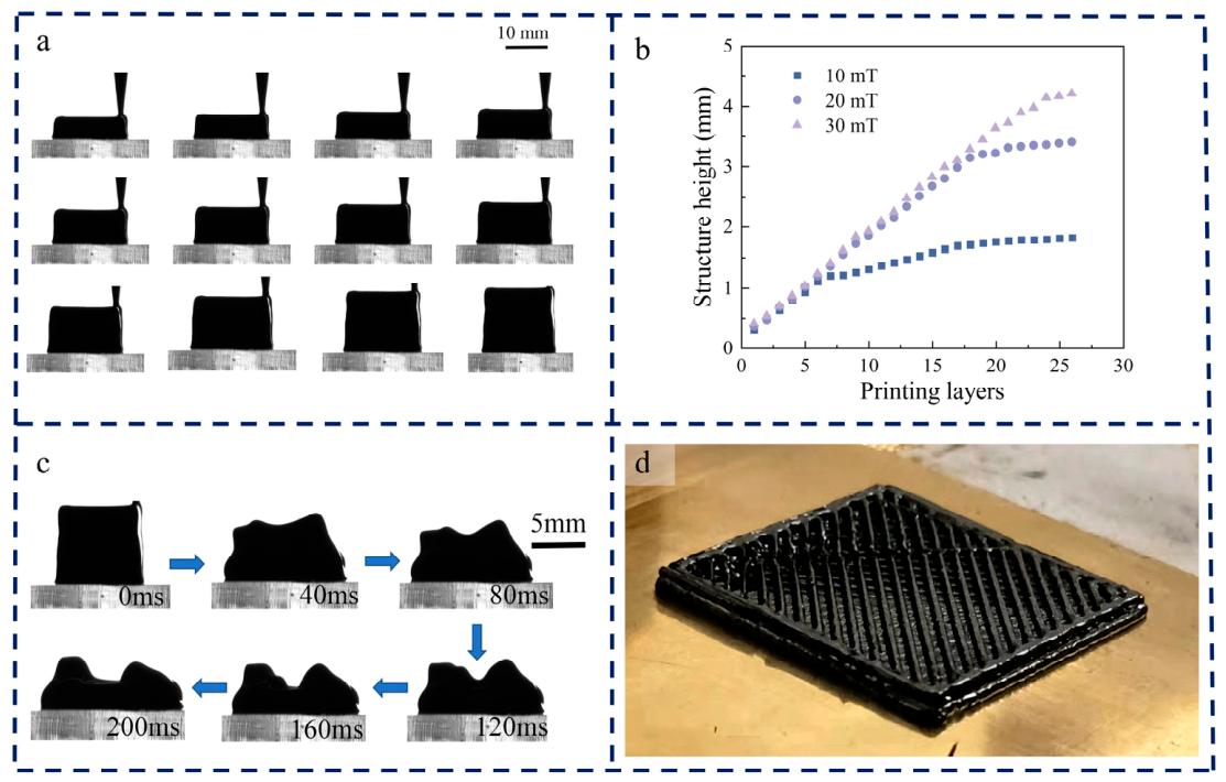
The self-supporting characteristics of MTFs are critical for determining both their maximum printable height and their capacity to provide structural support during composite printing processes. Based on the study of the thixotropic recovery properties of MTFs, we investigated the self-supporting properties of MTFs by printing a square cylinder structure. A 10 × 10 mm square base was selected for layer-by-layer stacking, with a single-layer printing height of 0.4 mm, as illustrated in Figure 9a. During the printing process, the structure is subject to gravity and shear forces due to the movement of the print head. These forces limit the print height, preventing infinite growth. As the number of printed layers increases, the shear stress within the printed structure caused by the gravity component gradually increases. When the local shear stress exceeds the material’s yield strength, internal flow occurs within the structure, leading to variations in thickness at different heights and causing the sides of the printed structure to transition from rectangular to trapezoidal shape. In Figure 9b, the relationship between the number of stacked layers and the resulting print height initially exhibits a linear increase under various magnetic field strengths. However, as the number of layers continues to rise, the rate of height increase slows, and the print height eventually stabilizes. This occurs because the material in the lower layers exceeds its yield stress, causing the upper layers to flow downward, resulting in uneven thicknesses across the structure. With increasing magnetic field strength, the anisotropic microstructures formed within the MTF become more complex and robust, enhancing the material’s yield stress. Consequently, the maximum achievable print height increases with the increased strength of the magnetic field.
Figure 9.
Research on the self-supporting characteristics of MTFs under different magnetic field intensities. (a) MTF square columnar structure printing process. (b) The relationship between the number of printing layers and the structural height under varying magnetic field conditions. (c) Collapse process of MTF square tube structure after removing the magnetic field. (d) Square structure with a straight-line 50% infill was printed.
The magnetically induced microstructure of the MTF can be thermodynamically decomposed, giving it reversible rheological properties, enabling a gel–sol transition similar to that of protoplasm in the printed structure. After the magnetic field is removed, the thermodynamic breakdown of the magnetic columnar structure weakens the connection between the hydrogen bonds in the bentonite laminates. This significantly reduces the material’s yield stress, preventing it from maintaining its self-supporting state. Due to the thixotropic nature of MTF, the collapse of the structure occurs gradually, with the side profile folding inward continuously. Using a high-speed camera to capture the side profile of the square cylinder at 40 ms intervals (Figure 9c), it was observed that the printed square cylinder collapsed after the magnetic field was withdrawn, with the most pronounced collapse occurring in the middle of the cylinder wall, where the structure was weakest. To investigate the ability of MTF to print arbitrary complex shapes, a three-dimensional model of a square structure with a straight-line 50% infill was printed, as shown in Figure 9d. The printed structure consists of five layers, with the infill lines oriented at 45° relative to the square edges. The printing interval between adjacent layers was set to 1 min. According to rheological data, this time allows the MTF sufficient thixotropic recovery, resulting in a high storage modulus before the next layer is printed, ensuring high molding precision. The final printed structure exhibited uniform width from top to bottom. The overall shape accuracy of the square was high, with clear boundaries at the right-angle corners. Moreover, the 45° straight infill lines were clearly distinguishable from one another, with no merging or blurring between adjacent lines, demonstrating the good printability of the MTF.
6. Fabrication and Actuation of Magnetically Deformable Smart Structures
6.1. Integrated Multi-Material Printing Process for Core–Shell Structures
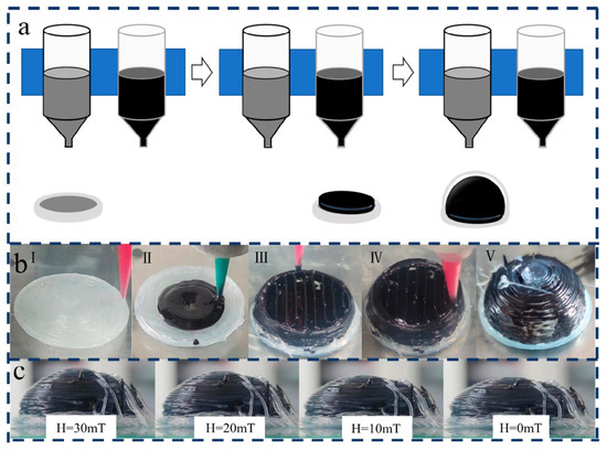
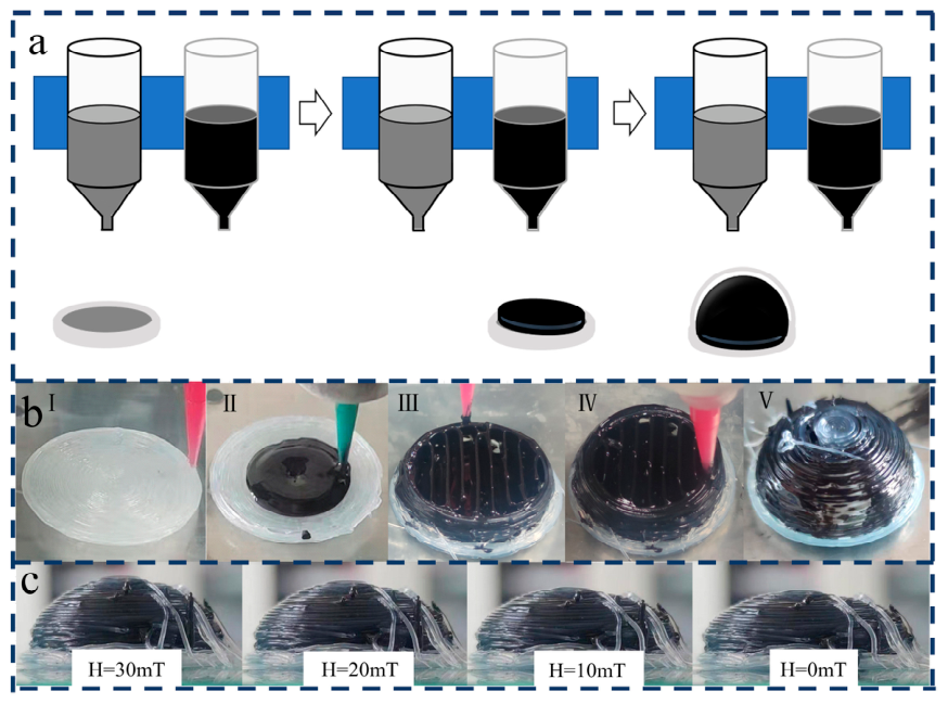
Due to the relatively low structural strength of silicone, creating large-span hollow dome shell structures through silicone 3D printing alone is not feasible. However, MTF can serve as a vital support during the silicone 3D printing process, leveraging its unique magnetorheological properties. Achieving integrated 3D printing of a core–shell soft structure requires careful coordination of MTF and silicone printing paths, precise control of the extrusion mechanism, and magnetic field application. Figure 10a illustrates the three sequential steps of the composite printing process. First, the bottom silicone layer is printed as the base. Second, MTF is deposited onto the silicone base, while simultaneously the silicone outer wall is printed around the MTF core. Finally, the silicone top layer is printed, completing the fabrication of the core–shell structure. A key challenge is the irregular interface between the silicone structure and MTF, which makes it difficult to achieve a standard MTF structure on the silicone base layer. To address this, we proposed a novel printing approach: First, a controlled amount of non-magnetized MTF is deposited onto the silicone base layer using a print head without applying a magnetic field. Due to MTF’s excellent fluidity, it easily fills the gaps between silicone filaments, forming a smooth surface. Subsequently, a moderate magnetic field is applied to facilitate layer-by-layer printing of the MTF structure on this prepared surface. To optimize support, we fine-tune the filling ratio and MTF placement method within the core–shell structure. Experimental analysis revealed that a vertical stripe pattern with a 25% filling ratio, as depicted in Figure 10b, yields the best results. Using this approach, we successfully fabricated a core–shell structure with a 10 mm diameter and a 0.6 mm membrane thickness, combining MTF and silicone. This innovative structure serves as a prototype for smart fluid-driven soft robots. After the silicone was fully cured, the magnetic field strength gradually reduced, inducing the MTF inside to undergo a gel-to-sol phase transition. Consequently, the MTF core structure lost its self-supporting capability and collapsed to varying degrees depending on the magnetic field strength. Without the support of the MTF, the silicone shell structure deformed elastically under gravity, maintaining constant contact with the MTF. As the MTF core structure collapsed further with the decreasing magnetic field, the overall height of the core–shell composite structure gradually reduced, as depicted in Figure 10c. In the presence of a gradient magnetic field, MTF within the elastic shell undergoes both gel–sol transitions and localized flow. By pre-programming an electromagnet array, continuous deformation of the printed structure becomes feasible. When the electromagnet generates a gradient magnetic field in a specified direction, the MTF flows within the cavity of the composite structure, causing localized deformations. Once the MTF transitions from sol to gel, the deformation stops. When the magnetic field is removed, the MTF returns to its sol state.
Figure 10.
Integrated 3D printing process for core–shell soft structure. (a) Schematic diagram of the integrated printing process for the MTF–silicone core–shell structure. (b) Optimized internal filling pattern (vertical stripes with 25% fill ratio) for the core structure. (c) Magnetic field-dependent overall height reduction in the core–shell structure.
6.2. Simulated and Experimental Deformation Under Gradient Magnetic Fields
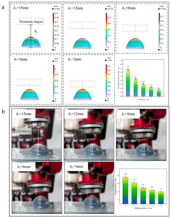
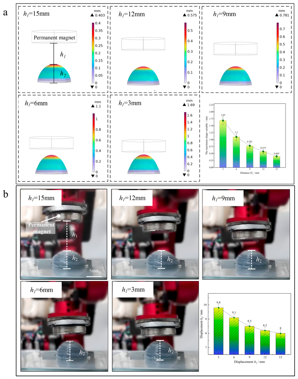
By varying the strength of the magnetic field, it is possible to achieve controllable adjustments in shape and deformation characteristics of the deformable smart structure. The deformation characteristics of the deformable smart structure at different distances h1 from the magnetic source were obtained using the finite element software COMSOL Multiphysics 6.1, as shown in Figure 11a.
Figure 11.
(a) Simulation obtained the deformation amplitude of amoeba-like soft robots with a permanent magnet at different distances. (b) Experimentally obtained deformation amplitude of amoeba-like soft robots with a permanent magnet at different distances.
By manipulating the permanent magnet to generate a gradient magnetic field in a specified direction, the MTF experiences directed flow within the cavity of the composite material structure, inducing localized deformations. It can obtain the deformation amplitude of amoeba-like soft robots as it increases with the increase in magnetic field. At h1 = 3 mm, the maximum deformation amplitude is 1.69 mm, and the maximum deformation rate at z-direction is (1.69/10) ×100% = 16.9% (hemispherical structure with a radius of 10 mm), which shows that the deformable smart structure based on MTF has good deformation ability under gradient magnetic field. 3D composite printing fabricates the deformable smart structure based on MTF (hemispherical structure with a radius of 10 mm) for further experiments, as shown in Figure 11b. Three independent samples of the optimal structure were fabricated, and all deformation data presented are mean values. The experimental results are consistent with the simulation results, with the deformation amplitude increasing as the distance h1 decreases.
The experimental results are consistent with the simulation results, and the deformation amplitude increases with the distance h1 reduction. However, when the distance h1 = 15 mm, h2 = 8 mm, which means that the height of the deformable smart structure is lower than when 3D composite printing is used. Due to the support of the magnetically controlled thixotropic fluid, the silicone shell structure experiences elastic deformation due to gravity, maintaining constant contact with the fluid, and the maximum deformation rate at z-direction is (1.8/8)×100% = 22.5%. By designing compressible and stretchable structures, the deformable smart structure can adapt to narrow spaces of different sizes and shapes, achieving precise navigation, reducing damage, improving therapeutic outcomes, and lowering risks. It is worth noting that the current deformation performance, while sufficient for concept validation, can be substantially improved in future work by introducing a magnetic yoke around the permanent magnet. Such a design would create a closed magnetic flux path, significantly enhancing field uniformity and gradient strength, which in turn would yield larger deformation amplitudes and more precise controllability—key factors for real-world applications in constrained environments.
7. Conclusions
This study focuses on soft robotics applications, preparing a novel magnetically controlled thixotropic fluid capable of reversible thixotropic sol–gel transition under a magnetic field. Based on the rheological characteristics of the ink, a specialized 3D printing platform equipped with an extrusion device was designed. Using this platform, we systematically studied the printing process of the material, optimized parameters to improve its printability, and achieved reversible 3D printing of complex deformable structures with phase transitions.
(1) The yield characteristics, linear viscoelastic properties, and thixotropic recovery characteristics of the magnetically controlled thixotropic fluid were tested. The experimental results showed that the magnetically controlled fluid exhibited secondary yield characteristics and double shear-thinning properties.
(2) At a magnetic field strength of 30 mT, the cross-sectional shape of MTF No. 2 achieved maximum height and fullness. Through research on printing recovery, it was found that at a printing speed of 5 mm/s, the recovery effect was good under the magnetic field, with a maximum printing height of 25 layers.
(3) In this paper, we achieved printing of hollow structures, completed composite printing of MTF and silicone materials, fabricated soft robots, and demonstrated controllable deformation of the composite structure under gradient magnetic fields.
Despite these achievements, several limitations remain. The current printing speed is constrained by the thixotropic recovery time of MTF, and the long-term stability of the fluid under cyclic magnetic actuation requires further investigation. Future work will focus on improving the material’s fatigue resistance and response speed, as well as optimizing the coil design for more compact and efficient magnetic field generation.
Author Contributions
Conceptualization, Z.L. and S.Z.; methodology, H.X.; software, J.D.; validation, H.X., Y.W. and Y.C.; formal analysis, H.W.; investigation, H.C.; resources, Z.L.; data curation, S.Z.; writing—original draft preparation, H.X.; writing—review and editing, Y.L.; visualization, S.Z.; supervision, Y.W.; project administration, Z.L.; funding acquisition, Z.L. and J.D. All authors have read and agreed to the published version of the manuscript.
Funding
This work was supported by the Natural Science Projects Funded by Hebei Province (No. E2024105049), the Fundamental Research Funds for the Central Universities (No. 2026JBZX034), the Science Research Project of Hebei Education Department (No. BJ2026292) and the Doctoral Research Startup Fund Project of Tangshan University (No. BC202423).
Data Availability Statement
The raw data supporting the conclusions of this article will be made available by the authors on request.
Conflicts of Interest
The authors declare no conflict of interest.
References
- Buchanan, C.; Gardner, L. Metal 3D printing in construction: A review of methods, research, applications, opportunities and challenges. Eng. Struct. 2019, 180, 332–348. [Google Scholar] [CrossRef] [Scilit]
- Subramani, R.; Mustafa, M.A.; Ghadir, G.K.; Al-Tmimi, H.M.; Alani, Z.K.; Rusho, M.A.; Rajeswari, N.; Rajan, A.J.; Kumar, A.P. Advancements in 3D printing materials: A comparative analysis of performance and applications. Appl. Chem. Eng. 2024, 7, 3867. [Google Scholar] [CrossRef] [Scilit]
- Diao, Q.; Zeng, Y.; Chen, J. The Applications and Latest Progress of Ceramic 3D Printing. Addit. Manuf. Front. 2024, 3, 200113. [Google Scholar] [CrossRef] [Scilit]
- Sano, J.; Matsuzaki, R. High accuracy 3D printing of composite materials using CNT yarns. Compos. Struct. 2023, 325, 117577. [Google Scholar] [CrossRef] [Scilit]
- Patel, P.; Dhal, K.; Gupta, R.; Tappa, K.; Rybicki, F.J.; Ravi, P. Medical 3D Printing Using Desktop Inverted Vat Photopolymerization: Background, Clinical Applications, and Challenges. Bioengineering 2023, 10, 782. [Google Scholar] [CrossRef] [Scilit] [PubMed]
- Xin, Y.; Zhou, X.; Bark, H.; Lee, P.S. The Role of 3D Printing Technologies in Soft Grippers. Adv. Mater. 2024, 36, 2307963. [Google Scholar] [CrossRef] [Scilit] [PubMed]
- Jiang, Y.; Islam, M.d.N.; He, R.; Huang, X.; Cao, P.-F.; Advincula, R.C.; Dahotre, N.; Dong, P.; Wu, H.F.; Choi, W. Recent Advances in 3D Printed Sensors: Materials, Design, and Manufacturing. Adv. Mater. Technol. 2023, 8, 2200492. [Google Scholar] [CrossRef] [Scilit]
- Quero, R.F.; da Silveira, G.D.; da Silva, J.A.F.; de Jesus, D.P. Understanding and improving FDM 3D printing to fabricate high-resolution and optically transparent microfluidic devices. Lab Chip 2021, 21, 3715–3729. [Google Scholar] [CrossRef] [Scilit] [PubMed]
- Mazhar, H.; Osswald, T.; Negrut, D. On the use of computational multi-body dynamics analysis in SLS-based 3D printing. Addit. Manuf. 2016, 12, 291–295. [Google Scholar] [CrossRef] [Scilit]
- Yang, G.; Guan, R.; Zhen, H.; Ou, K.; Fang, J.; Li, D.; Fu, Q.; Sun, Y. Tunable Size of Hierarchically Porous Alumina Ceramics Based on DIW 3D Printing Supramolecular Gel. ACS Appl. Mater. Interfaces 2022, 14, 10998–11005. [Google Scholar] [CrossRef] [Scilit] [PubMed]
- Dall’Argine, C.; Hochwallner, A.; Klikovits, N.; Liska, R.; Stampf, J.; Sangermano, M. Hot-Lithography SLA-3D Printing of Epoxy Resin. Macromol. Mater. Eng. 2020, 305, 2000325. [Google Scholar] [CrossRef] [Scilit]
- Elango, N.; Faudzi, A.A.M. A review article: Investigations on soft materials for soft robot manipulations. Int. J. Adv. Manuf. Technol. 2015, 80, 1027–1037. [Google Scholar] [CrossRef] [Scilit]
- Wang, L.; Peng, G.; Yao, W.; Biggar, S.; Hu, C.; Yin, X.; Fan, Y. 10—Soft robotics for hand rehabilitation. In Intelligent Biomechatronics in Neurorehabilitation; Hu, X., Ed.; Academic Press: Cambridge, MA, USA, 2020; pp. 167–176. [Google Scholar] [CrossRef] [Scilit]
- Cianchetti, M.; Laschi, C.; Menciassi, A.; Dario, P. Biomedical applications of soft robotics. Nat. Rev. Mater. 2018, 3, 143–153. [Google Scholar] [CrossRef] [Scilit]
- Bang, J.; Choi, S.H.; Pyun, K.R.; Jung, Y.; Hong, S.; Kim, D.; Lee, Y.; Won, D.; Jeong, S.; Shin, W.; et al. Bioinspired electronics for intelligent soft robots. Nat. Rev. Electr. Eng. 2024, 1, 597–613. [Google Scholar] [CrossRef] [Scilit]
- Ching, T.; Lee, J.Z.W.; Win, S.K.H.; Win, L.S.T.; Sufiyan, D.; Lim, C.P.X.; Nagaraju, N.; Toh, Y.-C.; Foong, S.; Hashimoto, M. Crawling, climbing, perching, and flying by FiBa soft robots. Sci. Robot. 2024, 9, eadk4533. [Google Scholar] [CrossRef] [Scilit] [PubMed]
- Wallin, T.J.; Pikul, J.; Shepherd, R.F. 3D printing of soft robotic systems. Nat. Rev. Mater. 2018, 3, 84–100. [Google Scholar] [CrossRef] [Scilit]
- Balani, S.B.; Ghaffar, S.H.; Chougan, M.; Pei, E.; Şahin, E. Processes and materials used for direct writing technologies: A review. Results Eng. 2021, 11, 100257. [Google Scholar] [CrossRef] [Scilit]
- Kuang, X.; Roach, D.J.; Wu, J.; Hamel, C.M.; Ding, Z.; Wang, T.; Dunn, M.L.; Qi, H.J. Advances in 4D Printing: Materials and Applications. Adv. Funct. Mater. 2018, 29, 1805290. [Google Scholar] [CrossRef] [Scilit]
- de Marco, C.; Pané, S.; Nelson, B.J. 4D printing and robotics. Sci. Robot. 2018, 3, eaau0449. [Google Scholar] [CrossRef] [Scilit] [PubMed]
- Deng, L.; Deng, J.; Guan, Z.; Tao, J.; Chen, Y.; Yang, Y.; Zhang, D.; Tang, J.; Li, Z.; Li, Z.; et al. Malus-metasurface-assisted polarization multiplexing. Light Sci. Appl. 2020, 9, 101. [Google Scholar] [CrossRef] [Scilit] [PubMed]
- Zhang, S.; Sun, X.; Song, Z.; Guo, Y.; Qu, J.; Li, Z. Study on a Novel Voxel-Based 3D Printing Method on Magnetic-Controlled Memory Fluid. In Proceedings of the 2023 IEEE 19th International Conference on Automation Science and Engineering (CASE), Auckland, New Zealand, 26–30 August 2023; pp. 1–6. [Google Scholar] [CrossRef] [Scilit]
- Deng, C.; Dong, J.; Guo, Y.; Sun, X.; Song, Z.; Li, Z. Amoeboid soft robot based on multi-material composite 3D printing technology. J. Magn. Magn. Mater. 2023, 588, 171390. [Google Scholar] [CrossRef] [Scilit]
- Cui, H.; Zhou, H.; Xu, H.; Deng, C.; Sun, X.; Lu, J.; Cheng, Y.; Xu, J.; Zhenkun, L. Designing and Fabrication of a Biomimetic Soft Gripper Utilizing Phase Transition 3D Printing Technology. Adv. Eng. Mater. 2025, 27, 2402501. [Google Scholar] [CrossRef] [Scilit]
- Zhao, S.; Zhang, J.-Y.; Fu, Y.; Zhu, S.; Shum, H.C.; Liu, X.; Wang, Z.; Ye, R.; Tang, B.Z.; Russell, T.P.; et al. Shape-Reconfigurable Ferrofluids. Nano Lett. 2022, 22, 5538–5543. [Google Scholar] [CrossRef] [Scilit] [PubMed]
- Nguyen, V.Q.; Ahmed, A.S.; Ramanujan, R.V. Morphing Soft Magnetic Composites. Adv. Mater. 2012, 24, 4041–4054. [Google Scholar] [CrossRef] [Scilit] [PubMed]
- Joseph, A.; Mathew, S. Ferrofluids: Synthetic Strategies, Stabilization, Physicochemical Features, Characterization, and Applications. ChemPlusChem 2014, 79, 1382–1420. [Google Scholar] [CrossRef] [Scilit]
- Tang, X.; Zhang, X.; Tao, R.; Rong, Y. Structure-enhanced yield stress of magnetorheological fluids. J. Appl. Phys. 2000, 87, 2634–2638. [Google Scholar] [CrossRef] [Scilit]
- Li, Z.; Li, D.; Chen, Y. Study on the yielding behaviors of ferrofluids: A very shear thinning phenomenon. Soft Matter 2020, 16, 8202–8212. [Google Scholar] [CrossRef] [Scilit] [PubMed]
- Li, Z.; Li, D.; Chen, Y.; Cui, H. Study of the thixotropic behaviors of ferrofluids. Soft Matter 2018, 14, 3858–3869. [Google Scholar] [CrossRef] [Scilit] [PubMed]
- Li, Z.; Dong, J.; Zhang, S.; Li, Y.; Deng, C.; Li, D.; Cui, H.; Li, Z.; Song, Z.; Yao, J.; et al. Phase transition reversible 3D printing of magnetic thixotropic fluid. Appl. Mater. Today 2023, 34, 101920. [Google Scholar] [CrossRef] [Scilit]

Disclaimer/Publisher’s Note: The statements, opinions and data contained in all publications are solely those of the individual author(s) and contributor(s) and not of MDPI and/or the editor(s). MDPI and/or the editor(s) disclaim responsibility for any injury to people or property resulting from any ideas, methods, instructions or products referred to in the content. |
© 2026 by the authors. Licensee MDPI, Basel, Switzerland. This article is an open access article distributed under the terms and conditions of the Creative Commons Attribution (CC BY) license.