


Abstract
The convex blazed grating is a key dispersive component in high-performance spectrometers, offering advantages such as a broad operating wavelength range, uniform dispersion, high diffraction efficiency, and the ability to achieve a large field of view. With the popularization of spectral detection technology and the ever-increasing demand for specialization, its design and fabrication technologies have drawn considerable attention in the field. This paper systematically reviews the development history of convex blazed grating design theory, from early scalar diffraction theory to the current mainstream rigorous vector methods, including rigorous coupled-wave analysis (RCWA), the finite-difference time-domain (FDTD) method, and commercial software such as Gsolver and PCGrate, and summarizes the applicable scenarios and limitations of each method. In terms of fabrication techniques, we comprehensively survey three typical technology routes—mechanical ruling, holographic ion beam etching, and electron beam lithography—covering their principles and progress, and analyze their respective merits and drawbacks in terms of precision, operating waveband, groove profile flexibility, and production capacity through comparative analysis. On this basis, we highlight recent breakthroughs achieved via electron beam lithography in blaze angle control and high-aspect-ratio etching for convex blazed gratings spanning from the ultraviolet to the very-long-wave infrared band; the diffraction efficiency has exceeded 80%, and such gratings have been successfully applied in aerospace engineering projects. Finally, this paper summarizes the current challenges facing convex blazed grating technology and provides an outlook on future development trends, including fabrication uniformity on curved substrates, large-area high-precision manufacturing, and design–process co-optimization, with the aim of offering a systematic reference for researchers and engineers in related fields.
1. Introduction
The spectral signature serves as an important “fingerprint” that reflects the composition and category of substances. Hyperspectral imaging technology in remote sensing established a three-dimensional observation system covering satellites, aviation, and ground platforms. It can simultaneously acquire spatial and spectral information of targets, realizing the “integration of imaging and spectroscopy”, and also possesses remarkable advantages such as high resolution and flexible measurement scales. This technology is widely used in geological observation, mineral identification, water quality monitoring, soil monitoring, crop growth and pest monitoring, carbon emission monitoring, vegetation coverage, environment monitoring, disaster emergency monitoring, and other industrial fields [1], marking a milestone in the development of remote sensing technology [2]. As a key component of hyperspectral imaging systems, the spectroscopic system directly determines the overall structural design of the spectrometer and ultimately restricts the performance of its major indicators. Owing to its curved surface and triangular groove profile, convex blazed gratings provide excellent imaging quality and high spectroscopic efficiency for spectroscopic systems, making them the crucial dispersive elements in spectrometers and spectroscopic systems [3,4,5].
In 1987, D. Kwo proposed a design of a reflective spectrometer based on the concentric three-mirror Offner optical system, in which a convex grating was used as the dispersive element [6]. The influence of grating groove density on dispersion width was analyzed, and a grating with a groove density of 15 gr/mm was selected for the 8–13 μm band. However, due to the limitations of manufacturing technology at that time, the production of convex blazed gratings was not feasible, so this design was not put into practical application. Ever since then, research achievements in convex grating fabrication began to emerge. In 1998, the U.S. Naval Research Laboratory, in collaboration with American Holographics Inc., analyzed the effects of rectangular and blazed groove profiles on the intensity of the first-order diffracted light of gratings, demonstrating that energy could be concentrated as much as possible into the first diffraction order through blazed groove profile design [7]. Two convex blazed gratings were fabricated via holographic ion beam etching: one for the visible band of 0.4–1.0 μm with a groove density of 155 gr/mm, and the other for the short-wave infrared (SWIR) band of 1.0–2.5 μm with a groove density of 62 gr/mm. The visible grating was reported to have a peak diffraction efficiency of 35% and a minimum diffraction efficiency of 20%. Also in 1998, Pantazis Mouroulis et al. from the NASA Jet Propulsion Laboratory (JPL) developed a convex grating for the Earth Observing-1 (EO-1) satellite imaging spectrometer of NASA’s New Millennium Program, featuring a blazed angle of less than 2°, a spectral range of 400–2500 nm, and a maximum efficiency of up to 85% [8]. In 2004, Galileo Avionica manufactured convex gratings with a groove density of 54 gr/mm and blazed angles ranging from 3° to 10°, which were successfully applied to the DAWN spacecraft and the Venus Express [9].
In 2010, a research team from Soochow University analyzed the theoretical influence of blazed angles on diffraction efficiency under TE and TM polarizations. By controlling the ion beam incident angle between 79° and 85° through substrate swing during fabrication, a convex blazed grating with a groove density of 200 gr/mm and a blazed angle of 4.3° was successfully developed, achieving a diffraction efficiency higher than 35% and a peak efficiency of nearly 55% in the 0.4–0.78 μm band [10]. In 2012, Yujuan Liu et al. from the Changchun Institute of Optics, Fine Mechanics and Physics, Chinese Academy of Sciences, developed a portable convex grating imaging spectrometer. A holographic convex grating with a groove density of 150 gr/mm was fabricated using holographic technology, reaching a maximum efficiency of 40% in the 400–800 nm band [11]. This grating had a rectangular groove profile, resulting in lower diffraction efficiency than blazed gratings. As a good reference, Wang et al. published a review in 2021 on the research progress in the design and fabrication of convex gratings that summarized advances in electron beam lithography (EBL), mechanical ruling, and holographic ion beam etching, with emphasis on the fabrication principle and process of holographic ion beam gratings [12].
In 2022, Yushi Zhao et al. from the Changchun University of Science and Technology designed and analyzed the groove parameters of gratings using the rigorous coupled-wave analysis (RCWA) method combined with the particle swarm optimization algorithm, and achieved a theoretical average diffraction efficiency of 85.47% [13]. A convex blazed grating was fabricated via mechanical ruling: it had a spectral range of 3–5 μm, a curvature radius of 120 mm, a groove density of approximately 10 gr/mm, a blazed angle of 1.1783°, a peak diffraction efficiency of 93.46%, and an average efficiency of 84.29%, with experimental results consistent with theoretical design. In 2024, noting that the efficiency of holographic ion beam gratings could not meet technical requirements, Fan et al. developed convex blazed gratings via mechanical ruling with a groove density of 58 gr/mm, achieving +1st-order diffraction efficiency exceeding 50% in the 360–850 nm band [14]. The second-order diffraction efficiency was also tested, showing high second-order efficiency at short wavelengths. In 2025, Liu et al. from Tongji University fabricated planar dual-blazed gratings using grayscale electron beam lithography (g-EBL) [15]. By optimizing the grating layout and exposure dose, dual-blazed gratings (1.8° and 3.5°) with aligned central heights were successfully prepared, achieving an average diffraction efficiency of 53% in the wavelength range of 0.4–1.05 μm. In the same year, Zelin Li conducted a study based on rigorous coupled-wave analysis (RCWA), the dispersion model of aluminum (Al), and experimental validation [16]. The simulation results show that for a grating with a groove density of 600 lines/mm and a blaze angle of 2°, both TE and TM efficiencies exceed 80% at a wavelength of 116 nm, while the degree of polarization (PD) remains below 0.6%; the small blazed angle plays a dominant role in suppressing the polarization. For the fabricated grating sample, the simulated TE and TM efficiencies and PD values across the 260–1000 nm wavelength range agree closely with the experimental measurements, validating the effectiveness of the modeling method. When the blaze wavelength is 123 nm, both the TE and TM efficiencies of the grating can be maintained above 85%, with an extremely low degree of polarization (approximately 0.16%), offering valuable guidance for the engineering implementation of polarization-independent imaging. In the same year, Chen Pengyuan et al. reviewed the domestic and international research progress on broadband gratings and compared the characteristics of four types of broadband gratings: complex-groove blazed gratings, segmented blazed gratings, echelle gratings, and multilayer dielectric gratings [17]. Among them, complex-groove blazed gratings offer high spectral continuity and stable diffraction efficiency curves, but their quality is significantly influenced by fabrication accuracy. Segmented blazed gratings exhibit high design flexibility and mature fabrication processes, yet they suffer from phase mismatch and diffraction field discrepancies between sub-regions, making them susceptible to stray light interference. These two types of blazed gratings are suitable for broadband applications, and are capable of meeting wider spectral analysis demands over a broad wavelength range.
In 2021, the research team from the Nantong Yangtze Delta Academy of Intelligent Sensing (NAIS) and the Shanghai Institute of Technical Physics, Chinese Academy of Sciences (SITP, CAS), focused on the development of convex blazed gratings using electron beam lithography. They developed a visible convex grating with a blazed angle of 1.2° and a near-infrared (IR) convex grating with a blazed angle of 2.8°, with both achieving diffraction efficiencies of over 82%; moreover, the study realized the application of convex gratings in spaceborne hyperspectral cameras in China. At present, the wavelength range of the fabricated triangular-groove convex blazed gratings covers 0.2–16 μm, including ultraviolet (UV), visible, SWIR, thermal infrared, and very-long-wave infrared (VLWIR) bands, covering almost the full absorption spectrum of various measured substances in all aspects of applications.
The above studies indicate that the development trend of blazed gratings is to expand the spectral coverage through designs such as blaze angle optimization and multi-blaze gratings, which significantly enhances the detectable spectral range of spectrometers, and to achieve polarization-independent performance through specialized grating designs, thereby improving the detection accuracy of spectrometers.
This paper elaborates on the development status of convex gratings from the perspectives of various design methods and technical processes for convex grating groove fabrication, presenting typical parameters, performance indicators, and development trends. It is aimed to be a comprehensive reference for researchers, manufacturers, and application engineers to comprehensively and quickly understand convex gratings and their development overview. This paper is organized as follows. In Section 2, we review the design methods of convex grating from theoretical and practical perspectives, including RCWA, the finite-difference time-domain (FDTD) method, and designing using commercial software. In Section 3, we review three main fabrication technologies of convex gratins—holographic ion beam etching, mechanical ruling, and electron beam lithography—showing both the theory and manufacturing processes. Especially, we show the results of convex blazed gratings manufactured by the NAIS and SITP, and an electron beam lithography component recently manufactured by the CAS. Finally, we conclude this study in Section 4.
2. Design of Convex Gratings
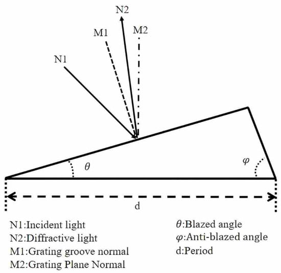
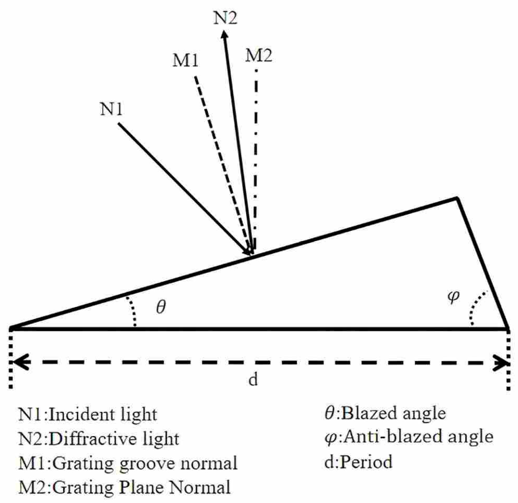
Diffraction efficiency is the major performance indicator of convex gratings, which directly affects the signal-to-noise ratio (SNR) of imaging spectrometer systems. Grating performance is considered optimal when diffraction efficiency reaches its maximum. The diffraction efficiency of a grating is directly determined by its groove profile. The geometry of a single triangular groove is illustrated in Figure 1. Here, M1 is the local surface normal of the grating blazed facet, M2 is the local surface normal of the grating substrate, N1 denotes the incident light, and N2 denotes the diffracted light. is the blazed angle, is the anti-blazed angle, and is the grating period. The groove profile is jointly determined by the blazed angle, anti-blazed angle, and grating period [18].
Figure 1.
Blazed grating grooves [17].
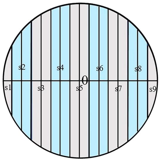
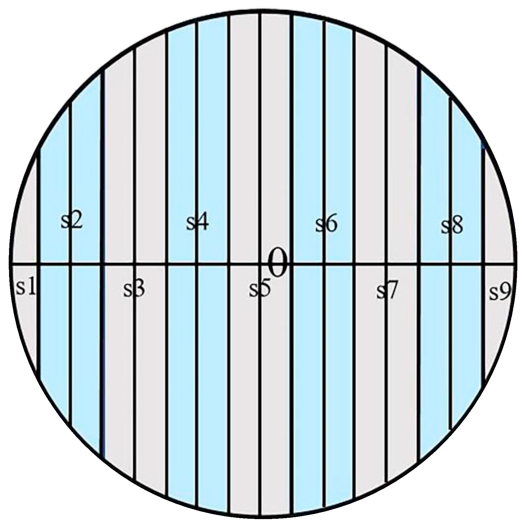
Commonly used grating analysis methods include scalar diffraction and vector diffraction. Scalar diffraction theory is applicable when the grating period is much larger than the wavelength and can provide approximate solutions, whereas vector diffraction theory is generally suitable for analyzing grating diffraction and can yield rigorous solutions [19]. The difference in convex blazed grating and planar grating designs lies in the fact that the incident angles of light rays vary at different positions on the convex surface, so the average diffraction efficiency must be calculated according to the incident angles at different locations [20]. As shown in Figure 2, the diffraction efficiency of a convex blazed grating is the average diffraction efficiency over regions S1 to S9. The crucial point in convex grating design is to maximize the diffraction efficiency by controlling the blazed angle while ensuring that the blazed wavelength meets the requirements of the spectral imaging system. This is generally realized in combination with the solar irradiance distribution and detector responsivity distribution, so as to compensate for the SNR by tuning the blazed wavelength of the grating.
Figure 2.
Schematic diagram of average diffraction efficiency calculation for convex blazed grating [17].
Theoretical design of convex diffraction gratings mainly adopts vector analysis methods, while practical design is implemented using commercial design software. In the following paragraphs, we review two vector analysis methods and the grating design results realized by commercial design software.
2.1. Vector Analysis Methods
2.1.1. RCWA
RCWA is a numerical method for simulating the propagation of electromagnetic waves in periodic photonic structures. By expanding electromagnetic fields using Fourier series and solving coupled-wave equations, it achieves high-precision calculations of diffraction efficiency and effectively handles complex boundary conditions and multilayer dielectric structures. In 1981, M. G. Moharam et al. first applied RCWA to analyze diffraction in planar gratings, and established a theoretical foundation for grating design and analysis [21]. In 2004, Bayanheshig used the RCWA theory to evaluate the degradation of diffraction efficiency caused by deviations in groove depth and duty cycle from design values, as well as the influence of lateral fabrication errors on stray light in rectangular gratings, providing valuable guidance for the application of RCWA in grating design and analysis [18]. In 2009, Wei Chen et al. from the CAS calculated the diffraction efficiencies of infrared gratings under TE and TM modes using RCWA, and analyzed the numerical instability resolved by the scattering matrix method, revealing the polarization-dependent diffraction characteristics of infrared gratings [19]. In 2019, Quan Liu et al. from Soochow University investigated the diffraction properties of convex gratings in the 0.4–0.9 μm band using this method [22]. It was found that the first-order diffraction efficiency could exceed 40% when the blazed angle was controlled within 5.9° to 7.1° for ideal performance, requiring strict error control within . This provided an analytical approach for process tolerance design of gratings. In 2023, Xu et al. optimized a planar grating with a high groove density of 1200 gr/mm and a small blazed angle [23]. They analyzed the influences of polarization, duty cycle, groove density, blazed angle, and other factors, and finally determined the optimized blazed angle within a precise range of , solving the problem of mask platforms at the top of grating ridges caused by process limitations.
2.1.2. FDTD
The finite-difference time-domain method is an electromagnetic calculation approach [24]. It discretizes Maxwell’s equations using spatial and temporal grids to solve the time-domain propagation of electromagnetic waves in complex media. In 2010, Li et al. used a self-programmed FDTD code to systematically study the polarization characteristics of near-ideal conductor blazed reflection gratings, revealing the influence of geometric and physical parameters on polarization states for wavelength-scale gratings [25]. Gao et al. established two grating structural models using the FDTD method. Optimization and analysis via the FDTD method provided a preliminary prototype for grating fabrication [26]. In 2016, Liang developed a frequency-dependent locally one-dimensional finite-difference time-domain (LOD-FDTD) method to analyze the extraordinary optical transmission (EOT) of periodic metal gratings [27]. Efficient preprocessing was conducted on the lower–upper (LU) decomposition in ADE-LOD-FDTD, and periodic boundary conditions (PBC) were applied to two-dimensional metal grating structures. Numerical calculations were performed on two cases with different subwavelength slits, and the mechanism of the EOT effect was investigated [27]. In 2018, Guo Peiliang adopted FDTD simulation to determine the parameters of convex dual-blazed gratings that satisfy diffraction efficiency requirements [28]. The influence of groove profile errors was analyzed and process tolerance was confirmed, offering direct theoretical guidance for homogeneous mask fabrication.
After decades of development, the RCWA and FDTD methods have become important tools for analyzing the diffraction efficiency of blazed gratings, supporting theoretical design and process tolerance analysis of gratings. The above design and analysis results show that a high-performance convex blazed grating requires strict control of the blazed angle within an allowable range and ensures that the grating grooves have an ideal triangular profile.
2.2. Commercial Design Software
As commercial software for grating design, PCGrate6.7 and Gsolver5.2 have been widely used in grating design. The PCGrate6.7 of grating design software is based on Fourier transform and adopts the RCWA algorithm for calculating diffraction efficiency. In 2019, Randall L. McEntaffer used this software to design reflection gratings and successfully applied them to the Lynx X-ray Grating Spectrometer (XGS), which adopted realizable grating parameters, efficiently arranged grating arrays, and a compact detector layout [29]. In 2020, Eduard Muslimov et al. used this software to design gratings, studied the requirements for manufacturing and assembly accuracy, and established performance criteria from three aspects: spectral resolution, calibration stability, and grating diffraction efficiency [30]. In 2022, Jared A. B. Termini et al. used this grating simulation software to determine relevant optimized parameters and defined crucial performance indicators of gratings for the next-generation UV space instruments [31]. In their work, the blazed angle ranged from 30° to 76° and the grating period ranged from 100 to 5000 nm. In 2023, Keri Hoadley et al. used PCGrate in their research to analyze grating parameters (polarization angle and grating period), optimized the design parameters of their previous UV gratings, and quantified the expected performance of UV gratings [32].
As a dedicated tool for grating structure design, Gsolverr5.2 can accurately design various types of grating structures, including holographic gratings, blazed gratings, and other gratings with various geometric profiles. Based on a full three-dimensional vector solution, Gsolver is capable of analyzing arbitrary polarization states, switching arbitrary diffraction orders, and performing order-by-order analysis of gratings. In 2013, Ge et al. from Soochow University used this software to simulate the diffraction efficiency of gratings with errors in the blazed angle, apex angle, and other parameters [33]. In 2018, Wang et al. used this software to simulate a double-layer nano-grating structure, analyzed its displacement trend, and obtained in-plane and out-of-plane displacement values by detecting the diffraction efficiency of the nano-gratings [34]. With their convenience and high efficiency, commercial software plays a significant role in the grating design industry. The differences between the aforementioned methods and software are shown in Table 1.
Table 1.
Comparison of design software for convex blazed gratings.
3. Fabrication Technologies for Convex Gratings
At present, convex gratings are mainly fabricated by holographic ion beam etching, mechanical ruling, and electron beam lithography. Among them, holographic ion beam etching is the most mature and widely used technology. The traditional mechanical ruling method can only produce planar gratings, while single-point diamond machining can be adopted for convex grating fabrication. Only electron beam lithography enables the preparation of high-efficiency convex gratings with small blazed angles.
3.1. Holographic Ion Beam Etching
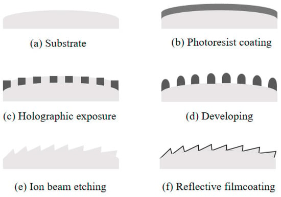
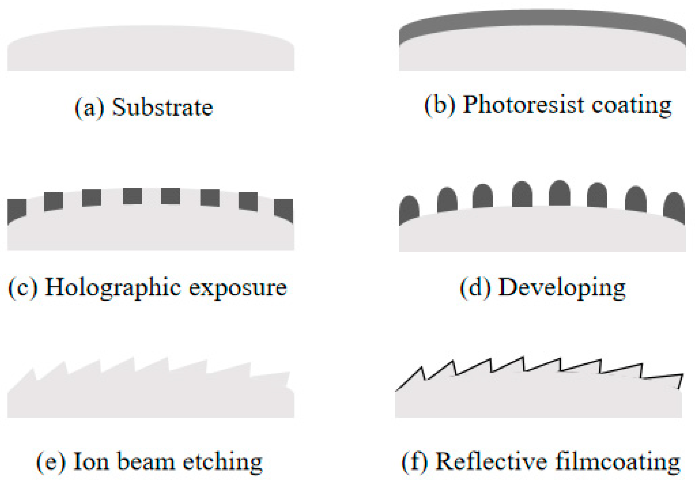
Holographic ion beam etching is a grating fabrication technology that gradually developed with the emergence of lasers in the last century and has been widely used to date. Yoshinobu Aoyagi and Susumu Namba first proposed the preparation of blazed holographic gratings by oblique argon ion beam etching of sinusoidal photoresist masks, and verified the method of ion beam control over the groove profile of holographic gratings [35]. Its fabrication process involves first forming a mask structure based on the principle of laser interference, which is then used to shield the substrate. Pattern transfer onto the substrate is achieved via ion beam etching. The blazed angle and triangular profile of the grating grooves are controlled by adjusting the duty cycle in holographic lithography and the tilt angle of the ion beam. The etching process is illustrated in Figure 3.
Figure 3.
Holographic ion beam etching process [36].
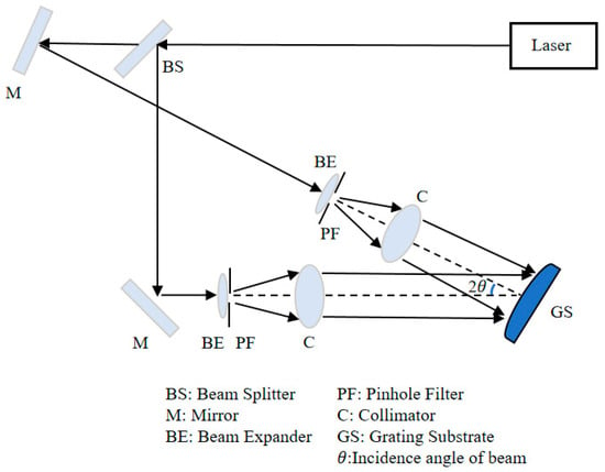
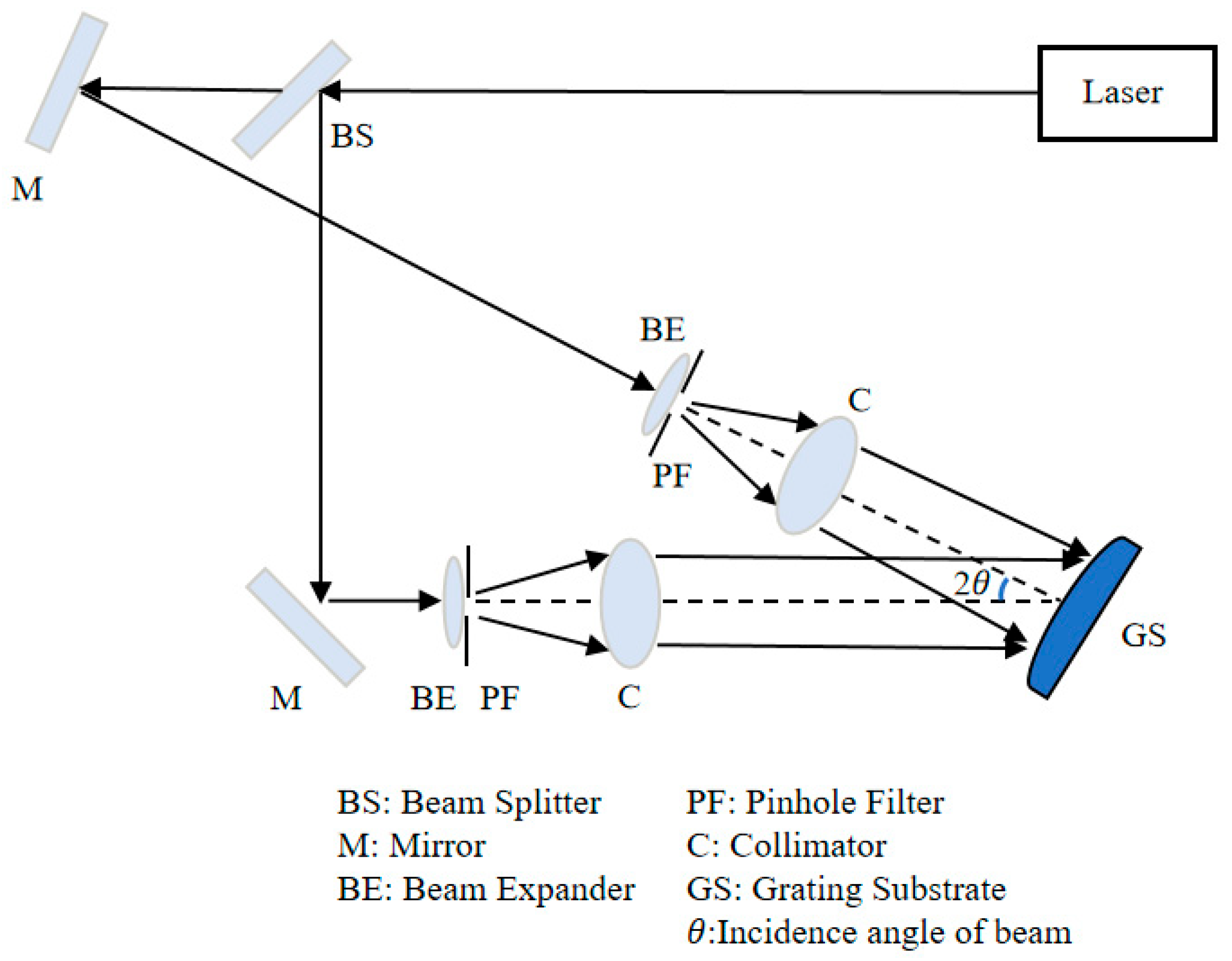
Holographic gratings fabricated by holographic technology utilize the interference principle of light. Fringes are formed via laser interference and recorded on photosensitive materials (such as photoresist), thereby achieving diffraction and phase modulation of light. The holographic optical layout is shown in Figure 4. Light emitted from the source passes through a beam splitter to produce two beams. These two laser beams travel through a series of mirrors to reach beam expanders and pinhole filters, generating spherical waves. The spherical waves are then collimated by collimators before illuminating the exposure sample (holographic plate). This process requires maintaining an identical optical path for the two beams. The uniformity and contrast of the two beams incident on the substrate affect the final mask profile; therefore, the contrast and uniformity of the two beams should be as consistent as possible.
Figure 4.
Optical path of holographic exposure [36].
If the intensities of the two beams are and with zero initial phase, according to the interference principle:
The phase difference between the two beams satisfies:
and the period of the interference fringes is obtained as
where is the grating period, is the laser wavelength, and is the incident angle of the light source. In the experiment, the two beams are incident symmetrically on the substrate, so we set . The grating period is then given by
Etching is performed using (reactive) ion beam etching. Fused silica glass is the most commonly used material for grating substrates at present; its main component is SiO2, and the corresponding etching gas is CHF3. Under natural conditions, CHF3 does not react with SiO2. When the etching gas CHF3 is ionized, the ionized ions physically etch the substrate and simultaneously react chemically with SiO2 to produce volatile gases, thereby completing the substrate etching. In 2010, the research team led by Tan Xin analyzed the factors influencing the diffraction efficiency of blazed gratings [37]. On this basis, they used an ion beam etching simulation program to simulate the etching process of planar blazed gratings, aiming to determine precise process parameters for practical fabrication. Based on the holographic ion beam etching process, two types of blazed gratings with a line density of 1200 gr/mm were successfully prepared, with blaze wavelengths of 250 nm and 330 nm, respectively. The two fabricated ultraviolet blazed gratings exhibited excellent performance. The first (blazed angle 8.54°) achieved a −1st-order diffraction efficiency of approximately 81% at 250 nm, and the second (blazed angle 11.68°) reached an efficiency of about 80% at 330 nm. The results demonstrated that this process can stably produce high-performance ultraviolet gratings with diffraction efficiency exceeding 75% on large-size substrates.
In 2011, the research team led by Wang successfully developed a convex blazed grating with a groove density of 200 gr/mm and a blazed angle of 4.3° [38]. In this study, a mask was fabricated via holographic ion beam etching, and a rotational scanning etching process was adopted. The developed grating achieved a diffraction efficiency of over 40% in the visible band. In 2018, the Changchun Institute of Optics, Fine Mechanics and Physics, in cooperation with the University of Chinese Academy of Sciences, developed a short-wave convex blazed grating using the swing etching method through high-precision adjustment of the ion beam incident angle, swing radius, and swing speed; the grating had a diameter of Φ67 mm and a curvature radius of 156.88 mm [39]. The grating had a groove density of 45.5 gr/mm and a blazed angle of 2.2°, with a peak diffraction efficiency of 90% at its operating wavelength.
In 2021, Zhong et al. summarized the research progress of convex blazed gratings fabricated by holographic ion beam swing etching, presenting the achievements of Soochow University and the Changchun Institute of Optics, Fine Mechanics and Physics, Chinese Academy of Sciences [36]. The smallest blazed angle was achieved by Cheng et al. from Soochow University at 1.8°, while the highest diffraction efficiency was obtained by the SWIR grating developed by the Changchun Institute of Optics, Fine Mechanics and Physics, with a peak efficiency of 90%. In 2024, Zhang et al. from Tsinghua University fabricated triangular planar gratings with controllable double-base angles and second-order blazed gratings on irregular film systems using the holographic ion beam etching process [40]. Triangular gratings with base angles of 20.9° and 89.0° were produced, with deviations of both base angles from the designed values not exceeding 1°. After nearly 50 years of development, holographic ion beam lithography has become increasingly mature. This method offers advantages such as the absence of spectral ghost lines and high diffraction efficiency, yet no successful processing results have been achieved for blazed gratings with small blazed angles and high-aspect-ratio grooves. As a comparison, we summarize the results mentioned in this section in Table 2.
Table 2.
Convex blazed grating manufactured by ion beam lithography mentioned in this article.
3.2. Mechanical Ruling
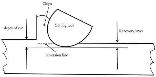
Traditional mechanical ruling is a technique that uses a diamond tool to form grating grooves through extrusion, polishing, and elastoplastic deformation of a metal coating. The essence of this process is a hybrid machining method combining ploughing and extrusion [41]. Grating grooves generally require strict parallelism and equal spacing, and the groove depth must remain uniform. Conventional mechanical ruling is typically only used to fabricate planar gratings and presents considerable difficulty for convex grating production. An illustration of mechanical ruling is shown in Figure 5.
Figure 5.
Principle of mechanical ruling [41].
With the advancement of ultra-precision machining technology, new fabrication methods have emerged in recent years for the precision manufacturing of convex gratings, such as single-point diamond turning, see Figure 6 for an illustration of the principle. Diamond turning controls the blazed angle and triangular profile of grating grooves by adjusting the tool inclination and cutting depth. Due to the excellent properties of single-crystal natural diamond tools, diamond turning can achieve machining results with lower residual stress and more desirable surface roughness.
Figure 6.
Principle of single-point diamond turning [42].
In 2016, Bourgenot Cyril et al. discussed a novel method for fabricating freeform gratings using diamond turning [42]. The study revealed significant variations between the material grooves. The uneven roughness across the grating facets was attributed to the occasional stretching of certain harder elements within the aluminum alloy, which significantly affected the surface roughness. It was determined that NiP (electroless nickel–phosphorus) could yield the best surface finish. Ultimately, the grating was successfully fabricated with a groove density of 100 gr/mm, an operating wavelength range of 400–700 nm, and an average roughness of 2.5 nm on each blaze facet.
In the same year, Liu et al. from the Industrial Technology Research Institute of Taiwan analyzed the effects of grating profile and period on diffraction efficiency and diffraction angle through numerical simulation, and experimentally verified the influences of profile design, grating period, and cutting speed on mold machining performance [43]. Using single-point diamond tools, they investigated the fabrication of high-precision roll-to-roll imprinting molds via diamond turning, and prepared subwavelength gratings using ultraviolet resin imprinting based on the roll-to-roll process. The results indicated that cutting speed and angle are the crucial factors affecting mold precision. Excessively high cutting speed leads to irregular grating periods. Optical measurements showed that gratings with uniform period and profile exhibited performance highly consistent with design parameters across different incident angles. The final results demonstrated that high-precision diamond-turning molds, with strictly controlled cutting parameters, provide an effective approach for the continuous mass production of subwavelength gratings.
In 2017, Xu et al. from the University of Rochester employed diamond turning by maintaining concentricity between the spherical tool aperture and the rotation axis, with tool movement from the lens edge toward the rotation center [44]. Convex blazed gratings with variable spacing were fabricated on a brass C46400 substrate, achieving a groove density of 300 gr/mm for the 500–1100 nm band, with surface roughness optimized below 18 nm. In 2020, Zheng et al. from the Nanjing University of Aeronautics and Astronautics successfully developed a convex blazed grating with a curvature radius of 70 mm, a groove density of 60 gr/mm, and a diameter of 52 mm [45]. A maximum relative diffraction efficiency exceeding 80% was achieved in the 1–2.5 μm spectral range. The grating had a blazed angle of 2.773°, an average groove spacing of 16.674 μm, and a maximum groove deviation μm. In 2021, Tan et al. from the National University of Singapore applied the Continuous Rotation Freeform Surface (CRFS) algorithm combined with a slow-slide servo system, and achieved precise control of grating fabrication with an average blazed angle of and surface roughness as low as 0.015 µm on high-curvature gratings [46]. In the same year, Graham Christopher et al. designed FYMOS, a rugged, lightweight, all-aluminum near-infrared hyperspectral moisture sensor imager based on freeform gratings, which was manufactured on a five-axis diamond machine [47]. In 2023, Huang et al. from the National University of Defense Technology derived accuracy formulas for convex blazed grating machining based on reflective blazed grating diffraction principles, analyzed the effects of tool nose radius and Poisson burrs on grating efficiency, and fabricated a convex blazed grating with a curvature radius of 41.104 mm, a substrate diameter of 14 mm, a groove density of 53.97 gr/mm, and a blazed angle of 3.86° using a four-axis ultra-precision machining system [48].
In recent years, diamond turning technology for gratings has advanced rapidly. This method offers advantages such as low cost, suitability for mass production, and high diffraction efficiency. However, it is mostly applicable to low groove density gratings and suffers from significant width inconsistency between adjacent grooves in practical production. We summarize the results mentioned in this section in Table 3.
Table 3.
Convex blazed grating manufactured by diamond turning mentioned in this article.
3.3. Electron Beam Lithography
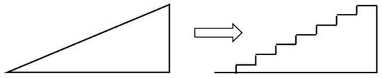
EBL is a technique that uses a focused high-energy electron beam to expose photoresist and form patterns through development. As an extension of photolithography, it does not require a photomask and can directly generate patterns, making it particularly suitable for fabricating fine micro- and nano-scale structures [49]. The triangular groove profile of a blazed grating can be approximated by a discretized step structure. This fabrication method requires the electron beam to perform scanning exposure with the step width as the step size, and the exposure dose must be quantitatively set according to the height of each step. Step-like grating grooves are formed after development. In this process, the fineness of step division is positively correlated with how closely the final profile approximates the ideal triangular sawtooth shape: finer steps yield a better approximation. Each step occupies one pixel, so each grating groove consists of multiple pixels. Different step heights require different exposure doses. During exposure, an electron beam with the same accelerating voltage and beam current is used, and the required exposure dose is controlled by adjusting the dwell time of the electron beam at each step height. The relevant principle is shown in Figure 7 below, and the calculation method is given by [50]:
where is the exposure dose in , is the incident electron beam current, is the dwell time of the electron beam scanning, and is the step pixel size. In electron beam lithography, the blazed angle and triangular profile of grating grooves are controlled by stepwise variation and lithographic dose modulation. Different blazed angles can be realized by different step gradients, avoiding the shadowing effect caused by height differences on curved substrates. Theoretically, gratings with arbitrary blazed angles can be fabricated.
Figure 7.
Principle of electron beam grayscale lithography [47].
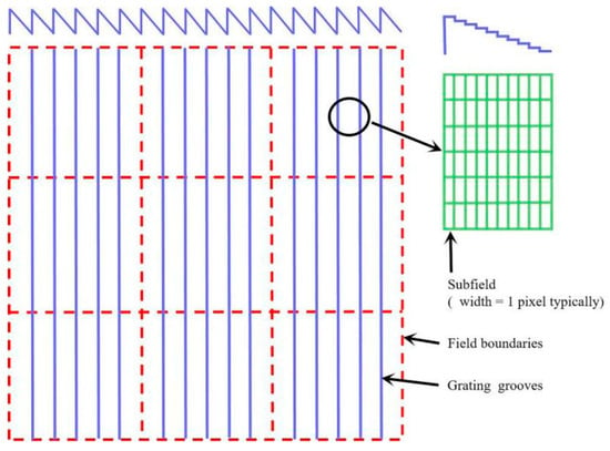
Figure 8 shows the grating writing mode, with the inset on the right illustrating the sub-field layout. The stitching accuracy between writing fields is controlled by a stage equipped with a laser interferometer [51].
Figure 8.
Writing mode of electron beam lithography [48].
The process principle of electron beam lithography is adopted for virtual mask design. During fabrication, the anti-blazed angle tends to be over-etched due to development effects, resulting in a reduced anti-blazed angle. Therefore, a groove profile with an anti-blazed angle of 90° is generally used in grating design. Since the maximum writable area in a single electron beam exposure is only approximately 1 mm2, a convex field stitching method is employed to divide the entire grating into multiple writing fields. Each writing field contains several grating grooves, and each groove is further subdivided into multiple sub-fields. Within each large writing field, the sample stage remains stationary, and the angular variation of adjacent grooves is realized by deflect scanning of the electron beam.
In 2000, JPL fabricated convex gratings for the Hyperion hyperspectral imager onboard the EO-1 satellite [52]. In 2003, JPL successfully developed electron beam-fabricated convex gratings for the Compact Reconnaissance Imaging Spectrometer for Mars (CRISM) [8]. This was a visible–near-infrared (VNIR) dual-blazed grating with blazed angles of 0.76° and 2.6°, respectively, and an effective aperture of 22.4 mm. In 2025, Liu et al. from Tongji University fabricated planar dual-blazed gratings using grayscale electron beam lithography (g-EBL) [15]. By optimizing the grating layout and exposure dose, dual-blazed gratings (1.8° and 3.5°) with aligned central heights were successfully prepared, achieving an average diffraction efficiency of 53% in the wavelength range of 0.4–1.05 μm.
The Shanghai Institute of Technical Physics, Chinese Academy of Sciences, has been engaged in the design, fabrication, and application of gratings since the late 20th century. Early planar gratings and PGP components were mainly imported from HORIBA Jobin Yvon (France) and the VTT Technical Research Centre of Finland, which were applied to airborne hyperspectral imagers such as OMIS and PHI [53,54,55]. Since 2000, the SITP of the CAS has conducted research on spaceborne hyperspectral imagers based on convex gratings, and launched the world’s first wide-spectrum, wide-swath hyperspectral camera in 2018 [2]. The employed self-developed convex gratings covered the spectral bands of 0.4–1.0 μm and 1.0–2.5 μm, with peak diffraction efficiencies exceeding 80%, blazed angles of 2.0° and 2.2°, respectively, and apertures larger than 60 mm. Limited by equipment conditions, the grating grooves were processed abroad.
Since 2019, the NAIS, in cooperation with the research team from the SITP of the CAS, has independently developed convex blazed gratings for spaceborne hyperspectral imaging covering ultraviolet to very-long-wave infrared bands (Table 4) using electron beam lithography. Meanwhile, concave gratings for handheld spectrometers have also been developed (Table 5). For gratings operating at 200–740 nm, aluminum is used as the reflective coating and fused silica as the substrate. For gratings operating at 740–16,000 nm, gold is used as the reflective coating and ULE zero expansion glass as the substrate. The diffraction efficiencies of gratings for 200–2500 nm are measured values, while those for 2500–16,000 nm are derived from fabricated groove profiles (after deducting a 3% coating loss).
Table 4.
Convex blazed grating manufactured by electron beam lithography involved in this article.
Table 5.
Concave gratings for handheld spectrometers involved in this article.
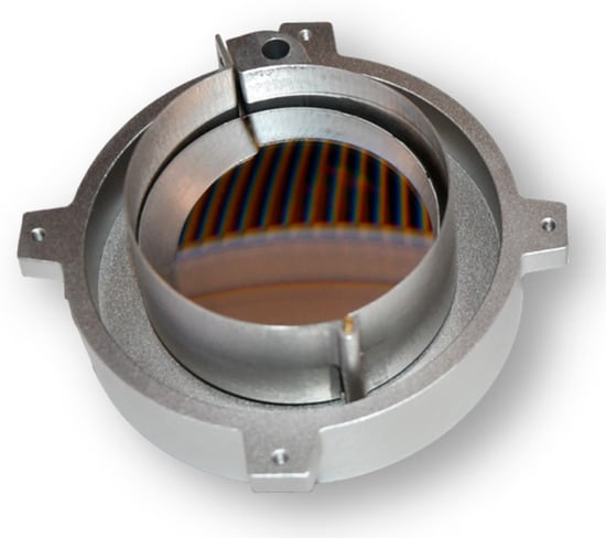
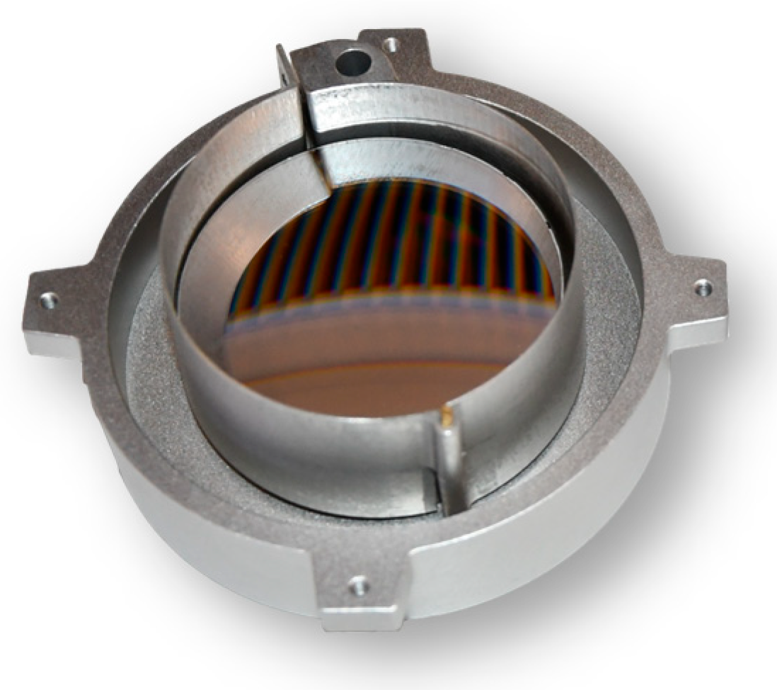
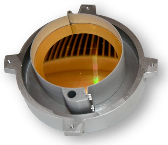
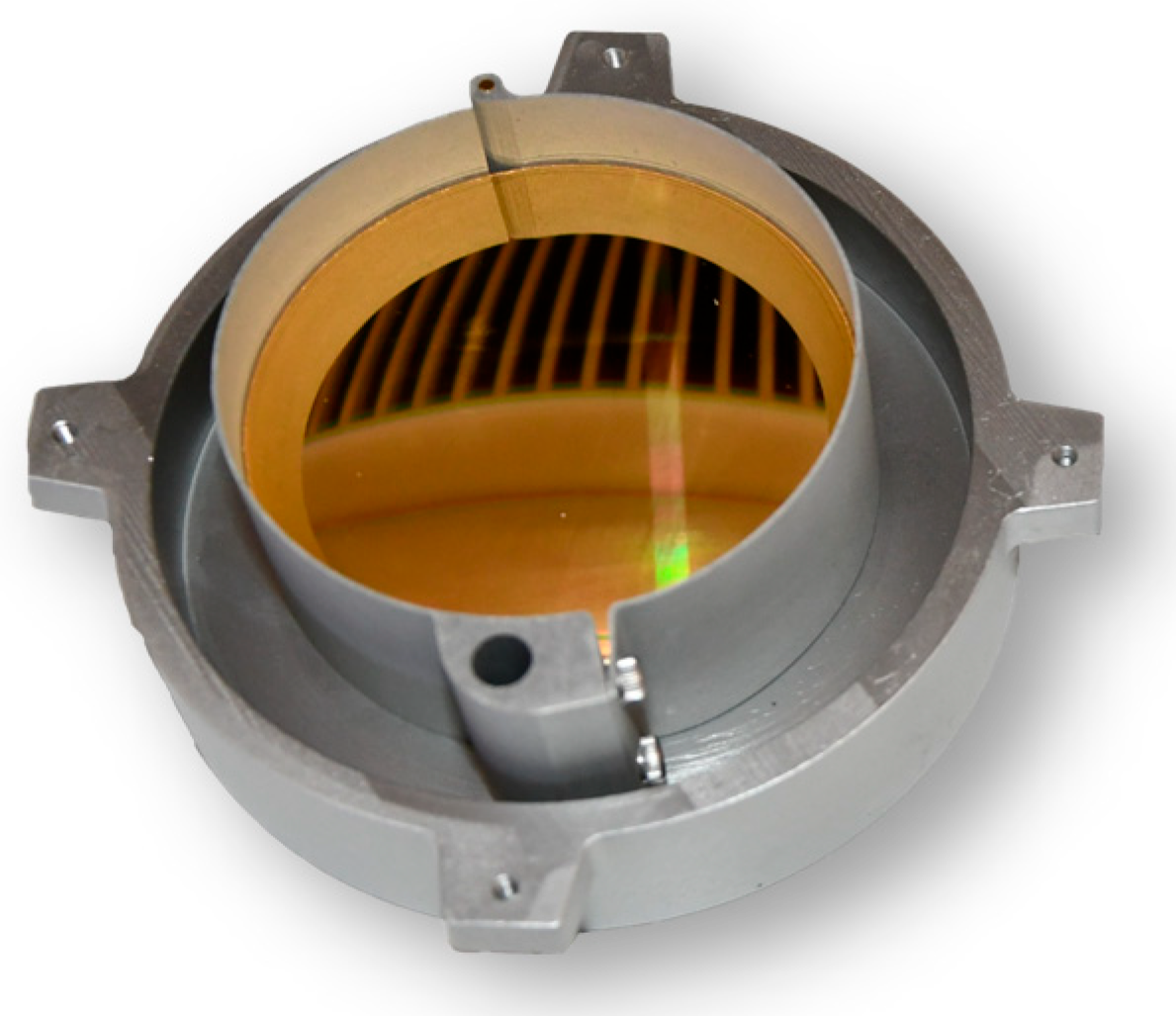
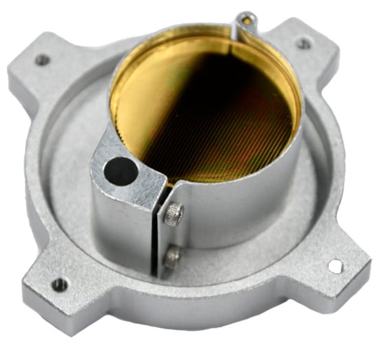
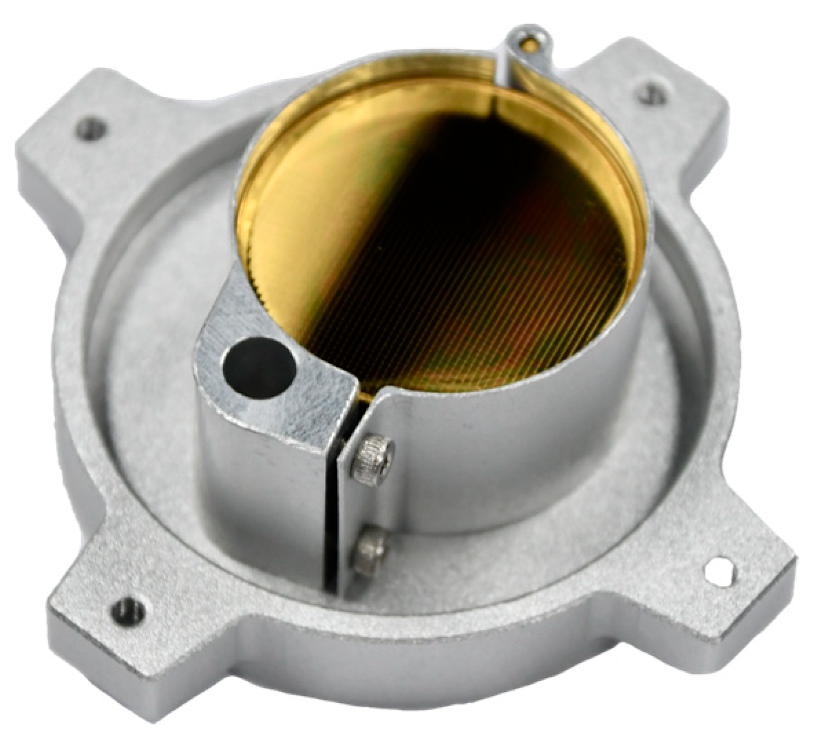
Figure 9, Figure 10 and Figure 11 present photographs and groove characterization results of convex gratings fabricated for the UV, SWIR (mid-band), and VLWIR bands, including small-blazed-angle UV gratings, large-aperture SWIR gratings, and high-aspect-ratio VLWIR gratings. The UV grating has a blazed angle of 0.48°, a period of 16.12 μm. The SWIR grating has a blazed angle of 2.8°, a period of 31.84 μm. The VLWIR grating has a blazed angle of 4.8°, a period of 55.86 μm.
Figure 9.
UV grating image.
Figure 10.
SWIR grating image.
Figure 11.
VLWIR grating image.
3.4. Process Summary
Gratings fabricated by holographic ion beam etching have superior advantages over other methods, such as lower stray light and the absence of ghosting issues encountered in other processes. However, since the period of holographic gratings is related to the wavelength of the laser source and the size of the holographic setup, this limits the achievable grating period. In general, gratings with low groove density and small blazed angles are not suitable for fabrication using the holographic method. Diamond turning offers the advantages of high processing speed, low cost, and high diffraction efficiency compared with other approaches, but it suffers from deviations in the period between adjacent grooves. Therefore, convex gratings with high groove density and small blazed angles are generally not suitable for diamond turning. The fabrication of convex gratings using electron beam lithography features high flexibility and high precision. Further improvement in diffraction efficiency can be achieved by reducing the size of lithographic steps, and it accommodates the widest range of groove densities and blazed angles, especially small ones. Nevertheless, it has the disadvantages of low processing speed and high cost. This method is more suitable for the development of high-performance master convex blazed gratings, which can then be mass-produced by replication. The specific differences among the three processing methods are shown in Table 6.
Table 6.
Side-by-side comparison of the three mainstream fabrication technologies for convex blazed gratings.
4. Conclusions
With the deepening of human understanding of the Earth and the expansion of extraterrestrial exploration activities, spectral imaging technology has been increasingly widely applied, covering basically all fields from ground-based, airborne, and spaceborne to deep-space applications. As one of the crucial components of spectroscopic devices, convex gratings have also undergone decades of development in design, analysis, and fabrication. This paper presents a relatively comprehensive review of relevant research work in the development of convex grating manufacturing. It can be seen that a variety of approaches are available for convex grating design and fabrication. Valuable exploration and advancement have been carried out in this field. At present, in terms of high-efficiency convex grating fabrication, the NAIS has covered the spectral range from UV to VLWIR. In particular, it has achieved remarkable breakthroughs in the fabrication of small-blazed-angle convex gratings, which is technically challenging. Nevertheless, this does not mean that convex grating fabrication has reached full maturity. Further research and efforts are still required to address the large-scale production of high-efficiency convex gratings and the fabrication of convex gratings for special applications.
In terms of fabrication techniques, electron beam lithography is highly equipment-dependent. Therefore, combining holographic ion beam and diamond turning to fabricate convex blazed gratings offers excellent synergy and complementarity. Specifically, the holographic ion beam is suitable for producing convex gratings with medium to high groove densities, while diamond turning excels at creating those with low groove densities. However, the former faces the challenge of perfectly forming triangular groove profiles, and the latter must address issues in fully guaranteeing the periodicity of mechanically ruled grooves. Looking ahead, with the rapid development of commercial satellites, the focus will increasingly shift towards technologies that enable rapid, mass replication of convex gratings. The development trend of blazed gratings is to expand the spectral coverage through designs such as blaze angle optimization and multi-blaze gratings, which significantly enhances the detectable spectral range of spectrometers, and to achieve polarization-independent performance through specialized grating designs, thereby improving the detection accuracy of spectrometers.
Author Contributions
Investigation, C.Z.; Writing—original draft preparation, P.Z.; Writing—review and editing, M.Y.; Supervision, Y.K.; Project administration, Y.L.; funding acquisition, M.Y. All authors have read and agreed to the published version of the manuscript.
Funding
This research was funded by the National Key R&D Program of China (Grant No. 2022YFB3902000) and the Major Program of the National Natural Science Foundation of China (Grant No. 42192582).
Data Availability Statement
No new data were created or analyzed in this study. Data sharing is not applicable to this article.
Conflicts of Interest
Author Mingliang Yao, Pengfei Zhao, and Chen Zhu was employed by the company Jiangsu JITRI Intelligent Sensing Technology Co., Ltd. The remaining authors declare that the research was conducted in the absence of any commercial or financial relationships that could be construed as a potential conflict of interest.
References
- Warnke, P.; Cuhls, K.; Schmoch, U.; Daniel, L. 100 Radical Innovation Breakthroughs for the Future; Directorate-General for Research and Innovation (European Commission): Brussels, Belgium, 2019. [Google Scholar] [CrossRef] [PubMed]
- Liu, Y.; Sun, D.; Hu, X.; Liu, S.; Cao, K.; Chai, M.; Liao, Q.; Zuo, Z.; Hao, Z.; Duan, W.; et al. Development of Visible and Short-Wave Infrared Hyperspectral Imager Onboard GF-5 Satellite. Natl. Remote Sens. Bull. 2020, 24, 333–344. [Google Scholar] [CrossRef] [Scilit]
- Sun, C.; Wang, M.; Cui, J.; Yao, X.; Chen, J. Comparison and Analysis of Wavelength Calibration Methods for Prism—Grating Imaging Spectrometer. Results Phys. 2019, 12, 143–146. [Google Scholar] [CrossRef] [Scilit]
- Liu, Y.; Sun, D.; Zhu, H.; Yuan, J. Development of Advanced Visible and Short-Wave Infrared Hyperspectral Imager On Board ZY-1-02D Satellite. Spacecr. Eng. 2020, 29, 85–92. [Google Scholar] [CrossRef]
- Shen, Y.; Ni, Z.; Huang, Y.; Xu, B.; Guo, B.; Wang, D. Research Progress of Concentric Imaging Spectrometer with Convex Grating. Laser Optoelectron. Prog. 2021, 58, 0900002. [Google Scholar] [CrossRef] [Scilit]
- Kwo, D.; Lawrence, G.; Chrisp, M. Design Of A Grating Spectrometer From A 1:1 Offner Mirror System. In Proceedings of the Current Developments in Optical Engineering II; SPIE: Bellingham, WA, USA, 1987; Volume 0818, pp. 275–281. [Google Scholar]
- Fisher, J.; Antoniades, J.; Rollins, C.; Xiang, L. A Hyperspectral Imaging Sensor for the Coastal Environment. In Proceedings of the International Optical Design Conference (1998); Paper LMD.5; Optica Publishing Group: Washington, DC, USA, 1998. [Google Scholar]
- Mouroulis, P.; Wilson, D.W.; Maker, P.D.; Muller, R.E. Convex Grating Types for Concentric Imaging Spectrometers. Appl. Opt. 1998, 37, 7200–7208. [Google Scholar] [CrossRef] [Scilit] [PubMed]
- Taylor, F.W. Introduction to the Venus Express Special Issue. Planet. Space Sci. 2006, 54, 1247–1248. [Google Scholar] [CrossRef] [Scilit]
- Liu, Q.; Wang, H.; Sun, P.; Wu, J. Fabrication of the Convex Blazed Grating. In Proceedings of the Holography, Diffractive Optics, and Applications IV; SPIE: Bellingham, WA, USA, 2010; Volume 7848, pp. 189–195. [Google Scholar]
- Liu, Y.; Cui, J.; Bayanheshig; Chen, S.; Qi, X.; Tang, Y. Design and Application of Imaging Spectrometer with Convex Grating. Opt. Precis. Eng. 2020, 20, 52–57. [Google Scholar] [CrossRef] [Scilit]
- Wang, D.; Zhang, D.; Xu, B.; Huang, Y.; Li, B.; Shen, Y. Research Progress in Design and Fabrication of Convex Grating. Laser Optoelectron. Prog. 2021, 58, 1100002. [Google Scholar]
- Zhao, Y.; He, W.; Liu, Z.; Fu, Y. Development of convex blazed grating in coded aperture spectral imager. Infrared Laser Eng. 2022, 51, 20220007. [Google Scholar] [CrossRef] [Scilit]
- Fan, J.; Wang, Y.; Gu, G.; Li, Z.; Wang, X.; Li, H.; Li, B.; Hu, D. Development of an Imaging Spectrometer with a High Signal-to-Noise Ratio Based on High Energy Transmission Efficiency for Soil Organic Matter Detection. Sensors 2024, 24, 4385. [Google Scholar] [CrossRef] [Scilit] [PubMed]
- Liu, L.; Zhang, X.; Zhu, J.; Dong, S.; Wei, Z.; Wang, Z.; Cheng, X. Optimizing and Well-Controlled Grayscale Electron Beam Lithography for Planar Dual-Blazed Grating Fabrication. Vacuum 2025, 240, 114540. [Google Scholar] [CrossRef] [Scilit]
- Li, Z.; Yu, H.; Wang, R.; Zhang, W.; Wang, J.; Li, W. High-efficiency polarization-independent low blaze angle ruled gratings in the Littrow mounting. Opt. Express 2025, 33, 46406–46425. [Google Scholar] [CrossRef] [Scilit] [PubMed]
- Chen, P.; Mi, X.; Li, S.; Jiang, S.; Zhou, J. Review of domestic and international research on broadband gratings. Opt. Precis. Eng. 2025, 33, 3593–3617. [Google Scholar] [CrossRef] [Scilit]
- Bayanheshig; Tang, Y.; Qi, X. The complete analytical form and analysis on angular dispersion formula of two-dimensional grating. Acta Phys. Sin. 2004, 53, 4181–4188. [Google Scholar] [CrossRef] [Scilit]
- Chen, W.; Sheng, L. Rigorous Coupled-Wave Method for Diffraction Efficiency Calculation of Blazed Gratings. J. Appl. Opt. 2009, 30, 734–738. [Google Scholar]
- Wang, H.; Wu, J.; Liu, Q. Diffraction characteristics of convex rectangular grating. Laser J. 2010, 31, 15–17. [Google Scholar] [CrossRef]
- Moharam, M.G.; Gaylord, T.K. Rigorous Coupled-Wave Analysis of Planar-Grating Diffraction. J. Opt. Soc. Am. 1981, 71, 811–818. [Google Scholar] [CrossRef] [Scilit]
- Liu, Q.; Wu, J.; Guo, P.; Chen, X. Fabrication of Convex Blazed Grating with High Diffraction Efficiency. Chin. J. Lasers 2019, 46, 0313001. [Google Scholar] [CrossRef] [Scilit]
- Xu, H.; Jiang, Y.; Chen, X.; Wang, R.; Zhang, J. Optimization of structural parameters and fabrication of monocrystalline silicon gratings with small blazed angle. Chin. Opt. 2024, 17, 1139–1149. [Google Scholar] [CrossRef] [Scilit]
- Hong, J.; Qiu, F.; Spring, A.M.; Yokoyama, S. Silicon Waveguide Grating Coupler Based on a Segmented Grating Structure. Appl. Opt. 2018, 57, 3301–3305. [Google Scholar] [CrossRef] [Scilit] [PubMed]
- Li, S.; Zhu, J.; Li, B.; Tang, T. Diffraction Polarization Characteristics for Blazed Reflection Gratings. Acta Photonica Sin. 2010, 39, 219–222. [Google Scholar] [CrossRef] [Scilit]
- Gao, J.; Chen, Y.; Huang, Q.; Zhang, X. Model Design of Grating Structure Based on FDTD. Pack. Eng. 2015, 36, 113–115. [Google Scholar]
- Liang, T.-L.; Shao, W.; Shi, S.-B.; Ou, H. Analysis of Extraordinary Optical Transmission With Periodic Metallic Gratings Using ADE-LOD-FDTD Method. IEEE Photonics J. 2016, 8, 7804710. [Google Scholar] [CrossRef] [Scilit]
- Guo, P.; Liu, Q.; Su, Y.; Lu, Y.; Wu, J. Fabrication of Convex Blazed Grating by Native Substrate Grating Mask. In Proceedings of the Sixth International Conference on Optical and Photonic Engineering (icOPEN 2018); SPIE: Bellingham, WA, USA, 2018; Volume 10827, p. 523. [Google Scholar]
- McEntaffer, R.L. Reflection Grating Concept for the Lynx X-Ray Grating Spectrograph. J. Astron. Telesc. Instrum. Syst. 2019, 5, 021002. [Google Scholar] [CrossRef] [Scilit]
- Muslimov, E.; Bouret, J.-C.; Neiner, C.; Ferrari, M.; Lombardo, S.; Ariste, A.L.; Gal, M.L. Precision Requirements for the POLLUX-LUVOIR Spectropolarimeter. In Proceedings of the Space Telescopes and Instrumentation 2020: Ultraviolet to Gamma Ray; SPIE: Bellingham, WA, USA, 2020; Volume 11444, pp. 1050–1059. [Google Scholar]
- Termini, J.A.B.; Hoadley, K.; DeRoo, C.; Fasano, C.; Hamden, E.; Li, J. Determining Ideal Grating Parameters for UV Blazed Gratings. In Proceedings of the Space Telescopes and Instrumentation 2022: Ultraviolet to Gamma Ray; SPIE: Bellingham, WA, USA, 2022; Volume 12181, pp. 717–732. [Google Scholar]
- Termini, J.A.B.; Hoadley, K.; DeRoo, C.; Fasano, C. Designing and Characterizing UV Gratings for Exoplanet Habitability Studies. In Proceedings of the UV, X-Ray, and Gamma-Ray Space Instrumentation for Astronomy XXIII; SPIE: Bellingham, WA, USA, 2023; Volume 12678, pp. 349–363. [Google Scholar]
- Ge, J.; Shen, W.; Liu, Q.; Chen, M. Effect of fabrication errors on the diffraction efficiency of sawtooth blazed grating. Infrared Laser Eng. 2013, 42, 1557–1561. [Google Scholar] [CrossRef] [Scilit]
- Wang, B.; Li, M.; Wu, Q.; Geng, H.; Wang, G. Simulation of Double Layer Nano-Gratings Micro-Displacement Detection. Instrum. Tech. Sens. 2018, 4, 6–9. [Google Scholar]
- Aoyagi, Y.; Namba, S. Blazing of Holographic Grating by Ion Etching Technique. Jpn. J. Appl. Phys. 1976, 15, 721. [Google Scholar] [CrossRef] [Scilit]
- Zhong, J.; Huang, Y.; Ni, Z.; Xu, B.; Zhang, D. Fabrication of convex blazed grating by holographic ion beam swing etching. Opt. Instrum. 2021, 43, 86–94. [Google Scholar]
- Tan, X.; Li, W.; Bayanheshig; Qi, X. Fabrication of ultraviolet holographic blazed grating. Opt. Precis. Eng. 2020, 18, 1536–1542. [Google Scholar]
- Wang, H.; Liu, Q.; Wu, J. Fabrication of Convex Blazed Grating By Ar+ Ion-Beam Etching. Acta Opt. Sin. 2011, 31, 0405002. [Google Scholar] [CrossRef] [Scilit]
- Shen, C.; Tan, X.; Jiao, Q.; Zhang, W.; Wu, N.; Bayan, H.; Qi, X. Convex Blazed Grating of High Diffraction Efficiency Fabricated by Swing Ion-Beam Etching Method. Opt. Express 2018, 26, 25381–25398. [Google Scholar] [CrossRef] [Scilit] [PubMed]
- Zhang, D. Fabrication of Triangular Gratings with Two Controllable Base Angles and High-Efficiency Gratings Made on Top of a Non-Periodic Multilayer Dielectric. Ph.D. Thesis, Tsinghua University, Beijing, China, 2024. [Google Scholar]
- Shi, G.; Shi, G.; Zhang, L.; Jiang, W. Finite Element Simulation Analysis of Mechanical Ruling of Diffraction Grating. Comput. Simul. 2012, 29, 103–106. [Google Scholar]
- Bourgenot, C.; Robertson, D.J.; Stelter, D.; Eikenberry, S. Towards Freeform Curved Blazed Gratings Using Diamond Machining. In Proceedings of the Advances in Optical and Mechanical Technologies for Telescopes and Instrumentation II; SPIE: Bellingham, WA, USA, 2016; Volume 9912, pp. 1135–1142. [Google Scholar]
- Liu, C.-W.; Yan, J.; Lin, S.-C. Diamond Turning of High-Precision Roll-to-Roll Imprinting Molds for Fabricating Subwavelength Gratings. Opt. Eng. 2016, 55, 064105. [Google Scholar] [CrossRef] [Scilit]
- Xu, D.; Owen, J.D.; Papa, J.C.; Reimers, J.; Suleski, T.J.; Troutman, J.R.; Davies, M.A.; Thompson, K.P.; Rolland, J.P. Design, Fabrication, and Testing of Convex Reflective Diffraction Gratings. Opt. Express 2017, 25, 15252–15268. [Google Scholar] [CrossRef] [Scilit] [PubMed]
- Zheng, Z.; Yang, Z.; Xiu, L. Development and Application of Shortwave Infrared Convex Blazed Grating with High Diffraction Efficiency. Acta Opt. Sin. 2020, 40, 1205002. [Google Scholar] [CrossRef] [Scilit]
- Tan, N.Y.J.; Zhou, G.; Liu, K.; Kumar, A.S. Diamond Shaping of Blazed Gratings on Freeform Surfaces. Precis. Eng. 2021, 72, 899–911. [Google Scholar] [CrossRef] [Scilit]
- Graham, C.; Girkin, J.M.; Bourgenot, C. Freeform Based hYperspectral Imager for MOisture Sensing (FYMOS). In Proceedings of the OSA Optical Sensors and Sensing Congress 2021 (AIS, FTS, HISE, SENSORS, ES) (2021); Paper HW6A.3; Optica Publishing Group: Washington, DC, USA, 2021. [Google Scholar]
- Li, H.; Peng, X.; Guan, C.; Hu, H. Ultra-Precision Cutting and Characterization of Reflective Convex Spherical Blazed Grating Elements. Micromachines 2022, 13, 1115. [Google Scholar] [CrossRef] [Scilit] [PubMed]
- Hu, W.; Sarveswaran, K.; Lieberman, M.; Bernstein, G.H. Sub-10 Nm Electron Beam Lithography Using Cold Development of Poly(Methylmethacrylate). J. Vac. Sci. Technol. B 2004, 22, 1711–1716. [Google Scholar] [CrossRef] [Scilit]
- Chen, Y.; Zhou, Z. A New Simulation Method for 3-D Electron Beam Lithography. In Proceedings of the 2023 IEEE International Conference on Manipulation, Manufacturing and Measurement on the Nanoscale (3M-NANO), Chengdu, China, 31 July–4 August 2023; pp. 25–29. [Google Scholar]
- Wilson, D.W.; Maker, P.D.; Muller, R.E.; Mouroulis, P.Z.; Backlund, J. Recent Advances in Blazed Grating Fabrication by Electron-Beam Lithography. In Proceedings of the Current Developments in Lens Design and Optical Engineering IV; SPIE: Bellingham, WA, USA, 2003; Volume 5173, pp. 115–126. [Google Scholar]
- Pearlman, J.S.; Barry, P.S.; Segal, C.C.; Shepanski, J.; Beiso, D.; Carman, S.L. Hyperion, a Space-Based Imaging Spectrometer. IEEE Trans. Geosci. Remote Sens. 2003, 41, 1160–1173. [Google Scholar] [CrossRef] [Scilit]
- Liu, Y. Development of Hyperspectral Imaging Remote Sensing Technology. Natl. Remote Sens. Bull. 2021, 25, 439–459. [Google Scholar] [CrossRef] [Scilit]
- Liu, Y.; Xue, Y.; Wang, J.; Shen, M. Operational modular imaging spectrometer. J. Infrared Milimeter Waves 2002, 21, 9. [Google Scholar]
- Li, H.; Shu, R.; Xue, Y. Pushbroom hyperspectral imager and its potential application to oceanographic remote sensing. J. Infrared Milimeter Waves 2002, 21, 429–433. [Google Scholar]

Disclaimer/Publisher’s Note: The statements, opinions and data contained in all publications are solely those of the individual author(s) and contributor(s) and not of MDPI and/or the editor(s). MDPI and/or the editor(s) disclaim responsibility for any injury to people or property resulting from any ideas, methods, instructions or products referred to in the content. |
© 2026 by the authors. Licensee MDPI, Basel, Switzerland. This article is an open access article distributed under the terms and conditions of the Creative Commons Attribution (CC BY) license.